EECS 242: RF Mixers UC Berkeley EECS 242 Copyright Prof. Ali M Niknejad
|
|
|
- Reginald Stafford
- 7 years ago
- Views:
Transcription


1 EECS 242: RF Mixers
2 Mixers The Mixer is a critical component in communication circuits. It translates information content to a new frequency. Information PSD Mixer
3 Why use a mixer (transmit side)? 1) Translate information to a frequency appropriate for transmission Example: Antennas smaller and more efficient at high frequencies 2) Spectrum sharing: Move information into separate channels in order to share spectrum and allow simultaneous use 3) Interference resiliance 1,2 3,4 Geographic map of cell sites 1,2
4 Why use mixer in the receiver? RF band Q of filter Desired channel Bandpass filter at ω o requires a high-q for narrowband signals Ch Δf ~ 200 khz (GSM) High Q
5 Mixers in Receivers (cont) High Q Insertion Loss Filter center frequency must change to select a given channel tunable filter difficult to implement Mixing has big advantage! Translate information down to a fixed (intermediate frequency) or IF. 1 GHz 10 MHz: 100x decrease in Q required Don t need a tunable filter High Q channel filter IF Issue: Mixer has high noise factor Superheterodyne receiver architecture
6 Mixers Specifications Conversion Gain: Ratio of voltage (power) at output frequency to input voltage (power) at input frequency Downconversion: RF power / IF power Up-conversion: IF power / RF power Noise Figure DSB versus SSB Linearity Image Rejection LO Feedthrough Input Output RF Feedthrough
7 Mixer Implementation We know that any non-linear circuit acts like a mixer Two tones ω 1, ω 2 f(x) Non-linear 2 nd order IM
8 Squarer Example x x 2 y DC & second harmonic Desired mixing Product component: What we would prefer: LO IF RF A true quadrant multiplier with good dynamic range is difficult to fabricate
9 LTV Mixer LTI No new frequencies LTV New tones in output Example: Suppose the resistance of an element is modulated harmonically
10 Time Varying Systems In general, any periodically time varying system can achieve frequency translation consider n=1 plus n=-1
11 Desired Mixing Product Output contains desired signal (plus a lot of other signals) filter out undesired components
12 Convolution in Frequency Ideal multiplier mixer: p(t) periodic input y(t) input x(t)
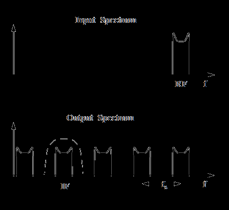
13 Convolution in Frequency (cont) X(f) f RF Translated spectrum peaks: X(f) peaks at f RF f Y(f) n=1 n=2 n=3 f Input spectrum is translated into multiple sidebands or image frequencies Also, the output at a particular frequency originates from multiple input frequency bands
14 How Low can you LO? Take the simplest mixer: output IF x(t) Side note: Which LO frequency to pick? LO1 or LO2? IF LO1 RF LO2 Low side injection High side injection Channel spacing No. of channels Tuning range: range f LO larger implies smaller tuning
15 Back to the original problem: Image Problem RF LO IMAGE RF LO IMAGE Question: Why filter before mixer in spectrum analyzer? Image reject filter Channel selection Answer: Image rejection IF Image reject filter LNA Receiver architecture is getting complicated LO
16 Origin of Image Problem If we could multiply by a complex exponential, then image problem goes away High side injection IF frequency (Low side injection) Image Freq.
17 Review of Linear Systems and PSD Average response of LTI system:
18 Average Value Property DC gain
19 Output RMS Statistics Recall the definition for the autocorrelation function
20 Autocorrelation Function since is a real and even function of ω is a real and even function of τ
21 Autocorrelation Function (2)
22 Average Power in X(t) Consider x(t) as a voltage waveform with total average power. Let s measure the power in x(t) in the band 0<ω<ω 1. + Ideal LPF The average power in the frequency range 0<ω<ω 1 is now W/radian W/Hz
23 Average Power in X(t) (2) Generalize: To measure the power in any frequency range apply an ideal bandpass filter with passband ω 1 < ω<ω 2 The interpretation of φ xx as the power spectral density (PSD) is clear
24 Spectrum Analyzer A spectrum analyzer measures the PSD of a signal Poor man s spectrum analyzer: Wide dynamic range mixer Sharp filter vertical Phase noise VCO Linear wide tuning range Sweep generation horiz. CRT
25 EECS 242: Current Commutating Active Mixers
26 Balanced Mixer An unbalanced mixer has a transfer function: Has DC which contains both RF, LO, and IF For a single balanced mixer, the LO signal is balanced (bipolar) so we have Has DC No DC As a result, the output contacts LO but no RF component For a double balanced mixer, the LO and RF are balanced so there is no LO or RF leakage
27 Noise in an Ideal Mixers Consider the simplest ideal multiplying mixer: RF IF Noise LO IF RF LO IM What s the noise figure for the conversion process? Input noise power due to source is ktb where B is the bandwidth of the input signal Input signal has power P s at either the lower or upper sideband
28 Noise in Ideal Mixers At the IF frequency, we have the down-converted signal G P s and down-converted noise from two sidebands, LO - IF and LO + IF For ideal mixer, G=G =G IF RF LO For a real mixer, noise from multiple sidebands can fold into IF frequency & degrade NF
29 Noise in CMOS Current Commutating Mixer (After Terrovitis, JSSC) I 1 I 2 LO RF M1 M3 M2 Assume i s is small relative to I B and perform Taylor series expansion v x -v x +1 All current through M1 M2 Both on
30 Noise in Current Commutating Mixers M1 M2 i 1 i 2 i s Note that with good device matching Expand p 1 (t) into a Fourier series: Only odd coefficients of p 1,n non-zero
31 Single Balanced Mixer + LO R L IF Switching Pair Assume LO signal strong so that current (RF) is alternatively sent to either M 2 or M 3. This is equivalent to multiplying i RF by ±1. - RF RF current M1 Transconductance stage (gain) Period waveform with period = T LO
32 Current Commutating Mixer (2) g(t) = square wave = Let gain LO-RF isolation good, but LO signal appears in output (just a diff pair amp). Strong LO might desensitize (limit) IF stage (even after filtering).
33 Double Balanced Mixer + LO - I D1 I D LO - Transconductance LO signal is rejected up to matching constraints Differential output removes even order non-linearities Linearity is improved: Half of signal is processed by each side Noise higher than single balanced mixer since no cancellation occurs

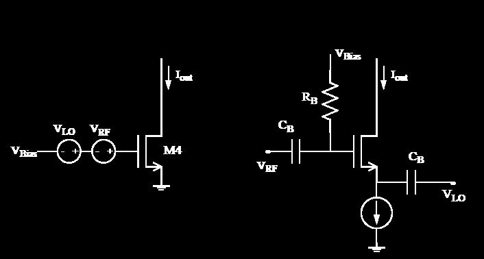
34 Common Gate Input Stage


35 Gilbert Micromixer The LNA output is often single-ended. A good balanced RF signal is required to minimize the feedthrough to the output. LC bridge circuits can be used, but the bandwidth is limited. A transformer is a good choice for this, but bulky and bandwidth is still limited. A broadband single-ended to differential conversion stage is used to generate highly balanced signals. Gm stage is Class AB.


36 Active and Passive Balun
 A current source can be used to feed the Gm stage with extra")
37 Bleeding the Switching Core Large currents are good for the gm stage (noise, conversion gain), but require large devices in the switching core hard to switch due to capacitance or requires a large LO (large Vgs-Vt) A current source can be used to feed the Gm stage with extra current.

38 Current Re-Use Gm Stage


39 Single, Dual, and Back Gate


40 Rudell CMOS Mixer Gain programmed using current through M16 (set by resistance of triode region devices M9/M10) Common mode feedback to set output point Cascode improves isolation (LO to RF)
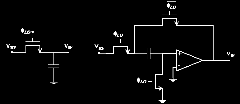
41 Passive Mixers/Sampling
42 Sub-Sampling Mixers

43 Triode Region Mixer
44 Improved Linearity LO, HIGH M2 M3 Cascode Amp To improve M 1, apply local series feedback RF M1 Provide input matching and feedback No DC headroom sacrificed RF Z s
45 Recap: CMOS Mixer Operation I 1 I 2 LO M1 M2 RF M3 Periodic Fourier Series expansion
46 References Noise in current-commutating CMOS mixers Terrovitis, M.T.; Meyer, R.G.; Solid-State Circuits, IEEE Journal of Volume 34, Issue 6, June 1999 Page(s): Intermodulation distortion in current-commutating CMOS mixers Terrovitis, M.T.; Meyer, R.G.; Solid-State Circuits, IEEE Journal of Volume 35, Issue 10, Oct Page(s): A systematic approach to the analysis of noise in mixers Hull, C.D.; Meyer, R.G.; Circuits and Systems I: Fundamental Theory and Applications, IEEE Transactions on [see also Circuits and Systems I: Regular Papers, IEEE Transactions on] Volume 40, Issue 12, Dec Page(s):
The front end of the receiver performs the frequency translation, channel selection and amplification of the signal.
 Many receivers must be capable of handling a very wide range of signal powers at the input while still producing the correct output. This must be done in the presence of noise and interference which occasionally
Introduction to Receivers
 Introduction to Receivers Purpose: translate RF signals to baseband Shift frequency Amplify Filter Demodulate Why is this a challenge? Interference (selectivity, images and distortion) Large dynamic range
Communication Systems
 AM/FM Receiver Communication Systems We have studied the basic blocks o any communication system Modulator Demodulator Modulation Schemes: Linear Modulation (DSB, AM, SSB, VSB) Angle Modulation (FM, PM)
AM TRANSMITTERS & RECEIVERS
 Reading 30 Ron Bertrand VK2DQ http://www.radioelectronicschool.com AM TRANSMITTERS & RECEIVERS Revision: our definition of amplitude modulation. Amplitude modulation is when the modulating audio is combined
RF Network Analyzer Basics
 RF Network Analyzer Basics A tutorial, information and overview about the basics of the RF Network Analyzer. What is a Network Analyzer and how to use them, to include the Scalar Network Analyzer (SNA),
Lecture 1: Communication Circuits
 EECS 142 Lecture 1: Communication Circuits Prof. Ali M. Niknejad University of California, Berkeley Copyright c 2005 by Ali M. Niknejad A. M. Niknejad University of California, Berkeley EECS 142 Lecture
Agilent AN 1316 Optimizing Spectrum Analyzer Amplitude Accuracy
 Agilent AN 1316 Optimizing Spectrum Analyzer Amplitude Accuracy Application Note RF & Microwave Spectrum Analyzers Table of Contents 3 3 4 4 5 7 8 8 13 13 14 16 16 Introduction Absolute versus relative
High-Frequency Integrated Circuits
 High-Frequency Integrated Circuits SORIN VOINIGESCU University of Toronto CAMBRIDGE UNIVERSITY PRESS CONTENTS Preface, page xiii Introduction l 1.1 High-frequency circuits in wireless, fiber-optic, and
Understanding Mixers Terms Defined, and Measuring Performance
 Understanding Mixers Terms Defined, and Measuring Performance Mixer Terms Defined Statistical Processing Applied to Mixers Today's stringent demands for precise electronic systems place a heavy burden
RF SYSTEM DESIGN OF TRANSCEIVERS FOR WIRELESS COMMUNICATIONS
 RF SYSTEM DESIGN OF TRANSCEIVERS FOR WIRELESS COMMUNICATIONS Qizheng Gu Nokia Mobile Phones, Inc. 4y Springer Contents Preface xiii Chapter 1. Introduction 1 1.1. Wireless Systems 1 1.1.1. Mobile Communications
Application Note Noise Frequently Asked Questions
 : What is? is a random signal inherent in all physical components. It directly limits the detection and processing of all information. The common form of noise is white Gaussian due to the many random
Voltage. Oscillator. Voltage. Oscillator
 fpa 147 Week 6 Synthesis Basics In the early 1960s, inventors & entrepreneurs (Robert Moog, Don Buchla, Harold Bode, etc.) began assembling various modules into a single chassis, coupled with a user interface
Optimizing IP3 and ACPR Measurements
 Optimizing IP3 and ACPR Measurements Table of Contents 1. Overview... 2 2. Theory of Intermodulation Distortion... 2 3. Optimizing IP3 Measurements... 4 4. Theory of Adjacent Channel Power Ratio... 9 5.
Probability and Random Variables. Generation of random variables (r.v.)
") Probability and Random Variables Method for generating random variables with a specified probability distribution function. Gaussian And Markov Processes Characterization of Stationary Random Process Linearly
Probability and Random Variables Method for generating random variables with a specified probability distribution function. Gaussian And Markov Processes Characterization of Stationary Random Process Linearly
MEASUREMENT UNCERTAINTY IN VECTOR NETWORK ANALYZER
 MEASUREMENT UNCERTAINTY IN VECTOR NETWORK ANALYZER W. Li, J. Vandewege Department of Information Technology (INTEC) University of Gent, St.Pietersnieuwstaat 41, B-9000, Gent, Belgium Abstract: Precision
Maximizing Receiver Dynamic Range for Spectrum Monitoring
 Home Maximizing Receiver Dynamic Range for Spectrum Monitoring Brian Avenell, National Instruments Corp., Austin, TX October 15, 2012 As consumers continue to demand more data wirelessly through mobile
Features. Applications. Transmitter. Receiver. General Description MINIATURE MODULE. QM MODULATION OPTIMAL RANGE 1000m
 Features MINIATURE MODULE QM MODULATION OPTIMAL RANGE 1000m 433.05 434.79 ISM BAND 34 CHANNELS AVAILABLE SINGLE SUPPLY VOLTAGE Applications IN VEHICLE TELEMETRY SYSTEMS WIRELESS NETWORKING DOMESTIC AND
Multi-Carrier GSM with State of the Art ADC technology
 Multi-Carrier GSM with State of the Art ADC technology Analog Devices, October 2002 revised August 29, 2005, May 1, 2006, May 10, 2006, November 30, 2006, June 19, 2007, October 3, 2007, November 12, 2007
Network Analyzer Operation
 Network Analyzer Operation 2004 ITTC Summer Lecture Series John Paden Purposes of a Network Analyzer Network analyzers are not about computer networks! Purposes of a Network Analyzer Measures S-parameters
Experiment 3: Double Sideband Modulation (DSB)
") Experiment 3: Double Sideband Modulation (DSB) This experiment examines the characteristics of the double-sideband (DSB) linear modulation process. The demodulation is performed coherently and its strict
Experiment 3: Double Sideband Modulation (DSB) This experiment examines the characteristics of the double-sideband (DSB) linear modulation process. The demodulation is performed coherently and its strict
Wireless Communication and RF System Design Using MATLAB and Simulink Giorgia Zucchelli Technical Marketing RF & Mixed-Signal
 Wireless Communication and RF System Design Using MATLAB and Simulink Giorgia Zucchelli Technical Marketing RF & Mixed-Signal 2013 The MathWorks, Inc. 1 Outline of Today s Presentation Introduction to
Agilent AN 1315 Optimizing RF and Microwave Spectrum Analyzer Dynamic Range. Application Note
 Agilent AN 1315 Optimizing RF and Microwave Spectrum Analyzer Dynamic Range Application Note Table of Contents 3 3 3 4 4 4 5 6 7 7 7 7 9 10 10 11 11 12 12 13 13 14 15 1. Introduction What is dynamic range?
HP 8970B Option 020. Service Manual Supplement
 HP 8970B Option 020 Service Manual Supplement Service Manual Supplement HP 8970B Option 020 HP Part no. 08970-90115 Edition 1 May 1998 UNIX is a registered trademark of AT&T in the USA and other countries.
Jeff Thomas Tom Holmes Terri Hightower. Learn RF Spectrum Analysis Basics
 Jeff Thomas Tom Holmes Terri Hightower Learn RF Spectrum Analysis Basics Learning Objectives Name the major measurement strengths of a swept-tuned spectrum analyzer Explain the importance of frequency
Constructing a precision SWR meter and antenna analyzer. Mike Brink HNF, Design Technologist.
 Constructing a precision SWR meter and antenna analyzer. Mike Brink HNF, Design Technologist. Abstract. I have been asked to put together a detailed article on a SWR meter. In this article I will deal
Visual System Simulator White Paper
 Visual System Simulator White Paper UNDERSTANDING AND CORRECTLY PREDICTING CRITICAL METRICS FOR WIRELESS RF LINKS Understanding and correctly predicting cellular, radar, or satellite RF link performance
T = 1 f. Phase. Measure of relative position in time within a single period of a signal For a periodic signal f(t), phase is fractional part t p
, phase is fractional part t p") Data Transmission Concepts and terminology Transmission terminology Transmission from transmitter to receiver goes over some transmission medium using electromagnetic waves Guided media. Waves are guided
Data Transmission Concepts and terminology Transmission terminology Transmission from transmitter to receiver goes over some transmission medium using electromagnetic waves Guided media. Waves are guided
How To Understand The Theory Of Time Division Duplexing
 Multiple Access Techniques Dr. Francis LAU Dr. Francis CM Lau, Associate Professor, EIE, PolyU Content Introduction Frequency Division Multiple Access Time Division Multiple Access Code Division Multiple
A Wideband mm-wave CMOS Receiver for Gb/s Communications Employing Interstage Coupled Resonators
 A Wideband mm-wave CMOS Receiver for Gb/s Communications Employing Interstage Coupled Resonators Federico Vecchi 1,2, Stefano Bozzola 3, Massimo Pozzoni 4, Davide Guermandi 5, Enrico Temporiti 4, Matteo
Revision of Lecture Eighteen
 Revision of Lecture Eighteen Previous lecture has discussed equalisation using Viterbi algorithm: Note similarity with channel decoding using maximum likelihood sequence estimation principle It also discusses
MAINTENANCE & ADJUSTMENT
 MAINTENANCE & ADJUSTMENT Circuit Theory The concept of PLL system frequency synthesization is not of recent development, however, it has not been a long age since the digital theory has been couplet with
RF Communication System. EE 172 Systems Group Presentation
 RF Communication System EE 172 Systems Group Presentation RF System Outline Transmitter Components Receiver Components Noise Figure Link Budget Test Equipment System Success Design Remedy Transmitter Components
AVX EMI SOLUTIONS Ron Demcko, Fellow of AVX Corporation Chris Mello, Principal Engineer, AVX Corporation Brian Ward, Business Manager, AVX Corporation
 AVX EMI SOLUTIONS Ron Demcko, Fellow of AVX Corporation Chris Mello, Principal Engineer, AVX Corporation Brian Ward, Business Manager, AVX Corporation Abstract EMC compatibility is becoming a key design
Evolution of Satellite Communication Systems
 Mathieu DERVIN Brussels, 6th May 2015 Brussels, May 2015 Agenda I. From Sputnik to wideband satellite services: The key technological evolutions II. Increase the satellite system capacity: A global system
Achieving New Levels of Channel Density in Downstream Cable Transmitter Systems: RF DACs Deliver Smaller Size and Lower Power Consumption
 Achieving New Levels of Channel Density in Downstream Cable Transmitter Systems: RF DACs Deliver Smaller Size and Lower Power Consumption Introduction By: Analog Devices, Inc. (ADI) Daniel E. Fague, Applications
OMNIYIG. .5 TO 2 GHz, 1 TO 4 GHz, 6 to 18 GHz Thin Film YIG-TUNED OSCILLATORS OUTLINE DIMESIONS MOUNTING SURFACE GND +15V + TUNE - HTR HTR
 . TO Hz, 1 TO Hz, to 1 Hz Thin Film YITUNED OSCILLATORS Highly Reliable StateoftheArt ThinFilm Technology s. to 1 Hz oscillators employ thinfilm technology, coupled with aas FET transistors, and were designed
Modulation Methods SSB and DSB
 Modulation Methods SSB and DSB William Sheets K2MQJ Rudolf F. Graf KA2CWL SSB or Single Sideband, is a type of AM without the carrier and one sideband. DSB or double sideband is AM with the carrier suppressed,
RF Measurements Using a Modular Digitizer
 RF Measurements Using a Modular Digitizer Modern modular digitizers, like the Spectrum M4i series PCIe digitizers, offer greater bandwidth and higher resolution at any given bandwidth than ever before.
Wide Band Tunable Filter Design Implemented in CMOS
 Wide Band Tunable Filter Design Implemented in CMOS W. Matthew Anderson and Bogdan M. Wilamowski Electrical & Computer Engineering Dept. Auburn University, AL 36849 anderwm@auburn.edu, wilambm@auburn.edu
CIRCUITS AND SYSTEMS Circuits and Systems for Radiofrequency and Telecommunications Dente Del Corso
 CIRCUITS AND SYSTEMS FOR RADIOFREQUENCY AND TELECOMMUNICATIONS Dante Del Corso Politecnico di Torino, Torino, Italy. Keywords: Heterodyne, direct conversion, ZIF, image frequency, mixer, SDR, LNA, PA,
In 3G/WCDMA mobile. IP2 and IP3 Nonlinearity Specifications for 3G/WCDMA Receivers 3G SPECIFICATIONS
 From June 009 High Frequency Electronics Copyright 009 Summit Technical Media, LLC IP and IP3 Nonlinearity Specifications for 3G/WCDMA Receivers By Chris W. Liu and Morten Damgaard Broadcom Corporation
RECOMMENDATION ITU-R BS.704 *, ** Characteristics of FM sound broadcasting reference receivers for planning purposes
 Rec. ITU-R BS.704 1 RECOMMENDATION ITU-R BS.704 *, ** Characteristics of FM sound broadcasting reference receivers for planning purposes (1990) The ITU Radiocommunication Assembly, considering a) that
VCO Phase noise. Characterizing Phase Noise
 VCO Phase noise Characterizing Phase Noise The term phase noise is widely used for describing short term random frequency fluctuations of a signal. Frequency stability is a measure of the degree to which
Current Probes, More Useful Than You Think
 Current Probes, More Useful Than You Think Training and design help in most areas of Electrical Engineering Copyright 1998 Institute of Electrical and Electronics Engineers. Reprinted from the IEEE 1998
A Guide to Calibrating Your Spectrum Analyzer
 A Guide to Calibrating Your Application Note Introduction As a technician or engineer who works with electronics, you rely on your spectrum analyzer to verify that the devices you design, manufacture,
BASICS OF C & Ku BAND TRANSMISSIONS & LNBs
 Page 1 of 6 BASICS OF C & Ku BAND TRANSMISSIONS & LNBs A satellite broadcasts a few watts of microwave signals from the geostationary orbit 36,000 kilometers above the earth. The transmissions are also
Detecting Bridged Tap and Noise Interference in VDSL2 Access Networks using the JDSU SmartClass TPS
 Application Note Detecting Bridged Tap and Noise Interference in VDSL2 Access Networks using the JDSU SmartClass TPS The JDSU SmartClass TPS tester is the ideal tool for technicians who install, troubleshoot,
Impedance 50 (75 connectors via adapters)
") VECTOR NETWORK ANALYZER PLANAR TR1300/1 DATA SHEET Frequency range: 300 khz to 1.3 GHz Measured parameters: S11, S21 Dynamic range of transmission measurement magnitude: 130 db Measurement time per point:
VECTOR NETWORK ANALYZER PLANAR TR1300/1 DATA SHEET Frequency range: 300 khz to 1.3 GHz Measured parameters: S11, S21 Dynamic range of transmission measurement magnitude: 130 db Measurement time per point:
SIGNAL PROCESSING & SIMULATION NEWSLETTER
 1 of 10 1/25/2008 3:38 AM SIGNAL PROCESSING & SIMULATION NEWSLETTER Note: This is not a particularly interesting topic for anyone other than those who ar e involved in simulation. So if you have difficulty
'Possibilities and Limitations in Software Defined Radio Design.
 'Possibilities and Limitations in Software Defined Radio Design. or Die Eierlegende Wollmilchsau Peter E. Chadwick Chairman, ETSI ERM_TG30, co-ordinated by ETSI ERM_RM Software Defined Radio or the answer
Chapter 6. CMOS Class-E Power Amplifier
 Chapter 6 CMOS Class-E Power Amplifier 6.0 Introduction Last few years have seen an increase in the popularity of the wireless communication systems. As a result, the demand for compact, low-cost, and
Test Report: Yaesu FTDX-1200, S/N 3F02051 (loaned by Bill Trippett W7VP)
") Test Report: Yaesu FTDX-1200, S/N 3F02051 (loaned by Bill Trippett W7VP) Adam M. Farson VA7OJ/AB4OJ, 19-21 July 2013 1. Introduction and Scope: The following tests were conducted on the FTDX-1200: A. Receiver
Test Report: Yaesu FTDX-1200, S/N 3F02051 (loaned by Bill Trippett W7VP) Adam M. Farson VA7OJ/AB4OJ, 19-21 July 2013 1. Introduction and Scope: The following tests were conducted on the FTDX-1200: A. Receiver
0HDVXULQJWKHHOHFWULFDOSHUIRUPDQFH FKDUDFWHULVWLFVRI5),)DQGPLFURZDYHVLJQDO SURFHVVLQJFRPSRQHQWV
,)DQGPLFURZDYHVLJQDO SURFHVVLQJFRPSRQHQWV") 0HDVXULQJWKHHOHFWULFDOSHUIRUPDQFH FKDUDFWHULVWLFVRI5),)DQGPLFURZDYHVLJQDO SURFHVVLQJFRPSRQHQWV The treatment given here is introductory, and will assist the reader who wishes to consult the standard texts
0HDVXULQJWKHHOHFWULFDOSHUIRUPDQFH FKDUDFWHULVWLFVRI5),)DQGPLFURZDYHVLJQDO SURFHVVLQJFRPSRQHQWV The treatment given here is introductory, and will assist the reader who wishes to consult the standard texts
Harmonics and Noise in Photovoltaic (PV) Inverter and the Mitigation Strategies
 Inverter and the Mitigation Strategies") Soonwook Hong, Ph. D. Michael Zuercher Martinson Harmonics and Noise in Photovoltaic (PV) Inverter and the Mitigation Strategies 1. Introduction PV inverters use semiconductor devices to transform the
Soonwook Hong, Ph. D. Michael Zuercher Martinson Harmonics and Noise in Photovoltaic (PV) Inverter and the Mitigation Strategies 1. Introduction PV inverters use semiconductor devices to transform the
UNDERSTANDING POWER FACTOR AND INPUT CURRENT HARMONICS IN SWITCHED MODE POWER SUPPLIES
 UNDERSTANDING POWER FACTOR AND INPUT CURRENT HARMONICS IN SWITCHED MODE POWER SUPPLIES WHITE PAPER: TW0062 36 Newburgh Road Hackettstown, NJ 07840 Feb 2009 Alan Gobbi About the Author Alan Gobbi Alan Gobbi
INTRODUCTION TO COMMUNICATION SYSTEMS AND TRANSMISSION MEDIA
 COMM.ENG INTRODUCTION TO COMMUNICATION SYSTEMS AND TRANSMISSION MEDIA 9/6/2014 LECTURES 1 Objectives To give a background on Communication system components and channels (media) A distinction between analogue
LM1596 LM1496 Balanced Modulator-Demodulator
 LM1596 LM1496 Balanced Modulator-Demodulator General Description The LM1596 LM1496 are doubled balanced modulator-demodulators which produce an output voltage proportional to the product of an input (signal)
RECOMMENDATION ITU-R SM.1792. Measuring sideband emissions of T-DAB and DVB-T transmitters for monitoring purposes
 Rec. ITU-R SM.1792 1 RECOMMENDATION ITU-R SM.1792 Measuring sideband emissions of T-DAB and DVB-T transmitters for monitoring purposes (2007) Scope This Recommendation provides guidance to measurement
RF IF. The World Leader in High-Performance Signal Processing Solutions. RF Power Amplifiers. May 7, 2003
 The World Leader in High-Performance Signal Processing Solutions RF Power Amplifiers May 7, 2003 Outline PA Introduction Power transfer characteristics Intrinsic PA metrics Linear and Non-linear amplifiers
Application Note Receiving HF Signals with a USRP Device Ettus Research
 Application Note Receiving HF Signals with a USRP Device Ettus Research Introduction The electromagnetic (EM) spectrum between 3 and 30 MHz is commonly referred to as the HF band. Due to the propagation
ELEMENTS OF CABLE TELEVISION
 1 ELEMENTS OF CABLE TELEVISION Introduction Cable television, from its inception, developed in western countries into two separate systems called Master Antenna Television (MATV) and Community Cable Television
Lecture 27: Mixers. Gilbert Cell
 Whites, EE 322 Lecture 27 Page 1 of 9 Lecture 27: Mixers. Gilbert Cell Mixers shift the frequency spectrum of an input signal. This is an essential component in electrical communications (wireless or otherwise)
AN1200.04. Application Note: FCC Regulations for ISM Band Devices: 902-928 MHz. FCC Regulations for ISM Band Devices: 902-928 MHz
 AN1200.04 Application Note: FCC Regulations for ISM Band Devices: Copyright Semtech 2006 1 of 15 www.semtech.com 1 Table of Contents 1 Table of Contents...2 1.1 Index of Figures...2 1.2 Index of Tables...2
Kit 106. 50 Watt Audio Amplifier
 Kit 106 50 Watt Audio Amplifier T his kit is based on an amazing IC amplifier module from ST Electronics, the TDA7294 It is intended for use as a high quality audio class AB amplifier in hi-fi applications
Jeff Thomas Tom Holmes Terri Hightower. Learn RF Spectrum Analysis Basics
 Jeff Thomas Tom Holmes Terri Hightower Learn RF Spectrum Analysis Basics Agenda Overview: Spectrum analysis and its measurements Theory of Operation: Spectrum analyzer hardware Frequency Specifications
Since any real component also has loss due to the resistive component, the average power dissipated is 2 2R
 Quality factor, Q Reactive components such as capacitors and inductors are often described with a figure of merit called Q. While it can be defined in many ways, it s most fundamental description is: Q
APPLICATION NOTES POWER DIVIDERS. Things to consider
 Internet Copy Rev A Overview Various RF applications require power to be distributed among various paths. The simplest way this can be done is by using a power splitter/divider. Power dividers are reciprocal
DT3: RF On/Off Remote Control Technology. Rodney Singleton Joe Larsen Luis Garcia Rafael Ocampo Mike Moulton Eric Hatch
 DT3: RF On/Off Remote Control Technology Rodney Singleton Joe Larsen Luis Garcia Rafael Ocampo Mike Moulton Eric Hatch Agenda Radio Frequency Overview Frequency Selection Signals Methods Modulation Methods
How To Use A Sound Card With A Subsonic Sound Card
 !"## $#!%!"# &"#' ( "#' )*! #+ #,# "##!$ -+./0 1" 1! 2"# # -&1!"#" (2345-&1 #$6.7 -&89$## ' 6! #* #!"#" +" 1##6$ "#+# #-& :1# # $ #$#;1)+#1#+
Agilent Spectrum Analysis Basics Application Note 150
 Agilent Spectrum Analysis Basics Application Note 150 Contents Chapter 1 Introduction...3 What is a spectrum?...3 Why measure spectra?...4 Chapter 2 The superheterodyne spectrum analyzer...6 Tuning equation...8
Common Mode Choke Filtering Improves CMRR in Ethernet Transformer Applications. Application Note. June 2011
 Common Mode Choke Filtering Improves CMRR in Ethernet Transformer Applications June 2011 Application Note Common mode chokes provide an effective EMI filtering solution for Ethernet transformer applications.
Experiment 7: Familiarization with the Network Analyzer
 Experiment 7: Familiarization with the Network Analyzer Measurements to characterize networks at high frequencies (RF and microwave frequencies) are usually done in terms of scattering parameters (S parameters).
CBS RECORDS PROFESSIONAL SERIES CBS RECORDS CD-1 STANDARD TEST DISC
 CBS RECORDS PROFESSIONAL SERIES CBS RECORDS CD-1 STANDARD TEST DISC 1. INTRODUCTION The CBS Records CD-1 Test Disc is a highly accurate signal source specifically designed for those interested in making
A Network Analyzer For Active Components
 A Network Analyzer For Active Components EEEfCom 29-30 Juni ULM Marc Vanden Bossche, NMDG Engineering Remi Tuijtelaars, BSW Copyright 2005 NMDG Engineering Version 2 Outline Review of S-parameters Theory
BSA Technical Information
 BSA Technical Information Electrical Isolation of Co-Located Horizontally and Vertically Stacked Antennas Introduction: Service providers are facing rapidly increasing pressure from zoning boards to co-locate
FUNDAMENTALS OF MODERN SPECTRAL ANALYSIS. Matthew T. Hunter, Ph.D.
 FUNDAMENTALS OF MODERN SPECTRAL ANALYSIS Matthew T. Hunter, Ph.D. AGENDA Introduction Spectrum Analyzer Architecture Dynamic Range Instantaneous Bandwidth The Importance of Image Rejection and Anti-Aliasing
RF and Microwave Accessories. CD-ROM Catalog. Find the right component for your Rohde & Schwarz test & measurement equipment
 RF and Microwave Accessories CD-ROM Catalog Find the right component for your Rohde & Schwarz test & measurement equipment Product group Typical applications Adapters Interchanging of various connector
Michael Hiebel. Fundamentals of Vector Network Analysis
 Michael Hiebel Fundamentals of Vector Network Analysis TABIH OF CONTENTS Table of contents 1 Introduction 12 1.1 What is a network analyzer? 12 1.2 Wave quantities and S-parameters 13 1.3 Why vector network
Tx/Rx A high-performance FM receiver for audio and digital applicatons
 Tx/Rx A high-performance FM receiver for audio and digital applicatons This receiver design offers high sensitivity and low distortion for today s demanding high-signal environments. By Wayne C. Ryder
Choosing a Phase Noise Measurement Technique Concepts and Implementation Terry Decker Bob Temple
 Choosing a Phase Noise Measurement Technique Concepts and Implementation Terry Decker Bob Temple RF & Microwave Measurement Symposium and Exhibition Terry Decker, received her BA in Physics from Carleton
VCO K 0 /S K 0 is tho slope of the oscillator frequency to voltage characteristic in rads per sec. per volt.
 Phase locked loop fundamentals The basic form of a phase locked loop (PLL) consists of a voltage controlled oscillator (VCO), a phase detector (PD), and a filter. In its more general form (Figure 1), the
RF SYSTEM DESIGN OF TRANSCEIVERS FOR WIRELESS COMMUNICATIONS
 RF SYSTEM DESIGN OF TRANSCEIVERS FOR WIRELESS COMMUNICATIONS RF SYSTEM DESIGN OF TRANSCEIVERS FOR WIRELESS COMMUNICATIONS Qizheng Gu Nokia Mobile Phones, Inc. Q - Springer Gu, Qizheng, 1936- RF system
Angle Modulation, II. Lecture topics FM bandwidth and Carson s rule. Spectral analysis of FM. Narrowband FM Modulation. Wideband FM Modulation
 Angle Modulation, II EE 179, Lecture 12, Handout #19 Lecture topics FM bandwidth and Carson s rule Spectral analysis of FM Narrowband FM Modulation Wideband FM Modulation EE 179, April 25, 2014 Lecture
HD Radio FM Transmission System Specifications Rev. F August 24, 2011
 HD Radio FM Transmission System Specifications Rev. F August 24, 2011 SY_SSS_1026s TRADEMARKS HD Radio and the HD, HD Radio, and Arc logos are proprietary trademarks of ibiquity Digital Corporation. ibiquity,
Four quadrant diode front end module for the Virgo Linear Alignment 3/ 30 mw, plus configuration
 NI K HEF NATIONAL INSTITUTE FOR NUCLEAR AND HIGH ENERGY PHYSICS Four quadrant diode front end module for the Virgo Linear Alignment 3/ 30 mw, plus configuration Find the most recent files and related files
Vi, fi input. Vphi output VCO. Vosc, fosc. voltage-controlled oscillator
 Experiment #4 CMOS 446 Phase-Locked Loop c 1997 Dragan Maksimovic Department of Electrical and Computer Engineering University of Colorado, Boulder The purpose of this lab assignment is to introduce operating
Agilent Spectrum Analysis Basics. Application Note 150
 Agilent Spectrum Analysis Basics Application Note 150 Table of Contents Chapter 1 Introduction.......................................................4 Frequency domain versus time domain.......................................4
AMICSA 2012. Integrated SAR Receiver/Converter for L, C and X bands Markku Åberg VTT Technical Research Centre of Finland
 AMICSA 2012 Integrated SAR Receiver/Converter for L, C and X bands Markku Åberg VTT Technical Research Centre of Finland 2 The Team Markku Åberg (1), Jan Holmberg (1), Faizah Abu Bakar (2), Tero Nieminen
DIODE CIRCUITS LABORATORY. Fig. 8.1a Fig 8.1b
 DIODE CIRCUITS LABORATORY A solid state diode consists of a junction of either dissimilar semiconductors (pn junction diode) or a metal and a semiconductor (Schottky barrier diode). Regardless of the type,
F = S i /N i S o /N o
 Noise figure Many receiver manufacturers specify the performance of their receivers in terms of noise figure, rather than sensitivity. As we shall see, the two can be equated. A spectrum analyzer is a
The Phase Modulator In NBFM Voice Communication Systems
 The Phase Modulator In NBFM Voice Communication Systems Virgil Leenerts 8 March 5 The phase modulator has been a point of discussion as to why it is used and not a frequency modulator in what are called
MSB MODULATION DOUBLES CABLE TV CAPACITY Harold R. Walker and Bohdan Stryzak Pegasus Data Systems ( 5/12/06) pegasusdat@aol.com
 pegasusdat@aol.com") MSB MODULATION DOUBLES CABLE TV CAPACITY Harold R. Walker and Bohdan Stryzak Pegasus Data Systems ( 5/12/06) pegasusdat@aol.com Abstract: Ultra Narrow Band Modulation ( Minimum Sideband Modulation ) makes
MSB MODULATION DOUBLES CABLE TV CAPACITY Harold R. Walker and Bohdan Stryzak Pegasus Data Systems ( 5/12/06) pegasusdat@aol.com Abstract: Ultra Narrow Band Modulation ( Minimum Sideband Modulation ) makes
GSM/EDGE Output RF Spectrum on the V93000 Joe Kelly and Max Seminario, Verigy
 GSM/EDGE Output RF Spectrum on the V93000 Joe Kelly and Max Seminario, Verigy Introduction A key transmitter measurement for GSM and EDGE is the Output RF Spectrum, or ORFS. The basis of this measurement
A Low Frequency Adapter for your Vector Network Analyzer (VNA)
") Jacques Audet, VE2AZX 7525 Madrid St, Brossard, QC, Canada J4Y G3: jacaudet@videotron.ca A Low Frequency Adapter for your Vector Network Analyzer (VNA) This compact and versatile unit extends low frequency
Jacques Audet, VE2AZX 7525 Madrid St, Brossard, QC, Canada J4Y G3: jacaudet@videotron.ca A Low Frequency Adapter for your Vector Network Analyzer (VNA) This compact and versatile unit extends low frequency
A CW QRP Transceiver for 20 m band. How it works I'll describe individually the three boards and the relative tuning devices.
 A CW QRP Transceiver for 20 m band The little QRP presented in this article may be built in a gradual manner, in fact it is divided in two main modules (plus VFO), you may also complete only a single part
How PLL Performances Affect Wireless Systems
 May 2010 Issue: Tutorial Phase Locked Loop Systems Design for Wireless Infrastructure Applications Use of linear models of phase noise analysis in a closed loop to predict the baseline performance of various
FILTERS - IN RADIO COMMUNICATIONS
 Reading 32 Ron Bertrand VK2DQ http://www.radioelectronicschool.com FILTERS - IN RADIO COMMUNICATIONS RADIO SIGNALS In radio communications we talk a lot about radio signals. A radio signal is a very broad
Vector Signal Analyzer FSQ-K70
 Product brochure Version 02.00 Vector Signal Analyzer FSQ-K70 July 2004 Universal demodulation, analysis and documentation of digital radio signals For all major mobile radio communication standards: GSM
Measurement of Adjacent Channel Leakage Power on 3GPP W-CDMA Signals with the FSP
 Products: Spectrum Analyzer FSP Measurement of Adjacent Channel Leakage Power on 3GPP W-CDMA Signals with the FSP This application note explains the concept of Adjacent Channel Leakage Ratio (ACLR) measurement
Spectrum Analysis Basics. Application Note 150
 Spectrum Analysis Basics Application Note 150 Agilent Technologies dedicates this application note to Blake Peterson. Blake s outstanding service in technical support reached customers in all corners of