Basic Ultrasound Physics
|
|
|
- Dominick Jacobs
- 9 years ago
- Views:
Transcription
1 Basic Ultrasound Physics Phase Amplitude A/D Frequency
2 Waves There are two types of waves: Transverse waves: these waves are perpendicular to the direction of energy transfer, e.g., violin string. Longitudinal waves: these waves are parallel to the direction of energy transfer, e.g., a pulse from a piston in a cylinder, sound waves. Rarefactions Compressions
3 What is Ultrasound? Ultrasound is a wave with a frequency exceeding the upper limit of human hearing greater than 20,000 Hz (hertz)
4 Waves We can measure longitudinal waves in two ways: Distance: the wave length Frequency: how many times per second the compression peak occurs at a point in space. 1 Cycle Time
5 Waves Frequency (f) and wavelength (λ) are related by the speed of sound in the medium: V=ƒ λ Generally speaking, V is related to the compressibility of the medium, slower in gasses, faster in liquids, and fastest in solids.
6 What is Sound? Sound is a mechanical wave that travels in a straight line Requires a medium through which to travel Rarefactions Compressions
7 What is Sound? Sound has: Energy: or work, in Joules (1 J = 1 kgm2/s2) Power: is rate of energy, in Watts (1 W = 1 J/s) Intensity: is pressure, force per unit area, in Pascals (1 P = 1 N/m2) Sound intensity/energy/power changes over many orders of magnitude. We use logarithmic measures, called decibels (db). A db is a dimensionless measure. It is a ratio. We pick some standard to measure, call it S0, and measure signal strength (intensity) w.r.t. S0. X (db) = 10 log10 (S/S0)
8 For example: S0=1: S=10, X=10 db S=2, X=3 db S=0.5, X=-3 db S=0.1, X=-10 db What is Sound?
9 What is Sound? Speed of sound in biological media:
10 Velocity (propagation speed) The speed with which a sound wave travels through a medium Units of measure are distance/time cm/sec The speed of sound is determined by the density and stiffness of the media in which it travels slowest in air/gasses fastest in solids Average speed of ultrasound in the body is 1540 m/sec
11 What is Sound? Energy loss is called attenuation. There are many mechanisms that cause that. The main ones we care about are: Absorption: conversion to heat Reflection: organized change in direction of the wave (specular: mirror like) Scatter: disorganized change in direction Attenuation is denoted by α, a coefficient that describes how energy is dissipated.
12 What is Sound? For biological tissues, α is poorly estimated.
13 Interactions of Ultrasound with Tissue
14 Interactions of Ultrasound with Tissue Reflection Scattering Transmission Attenuation
15 Interactions of Ultrasound with Tissue Reflection Scattering Transmission Attenuation
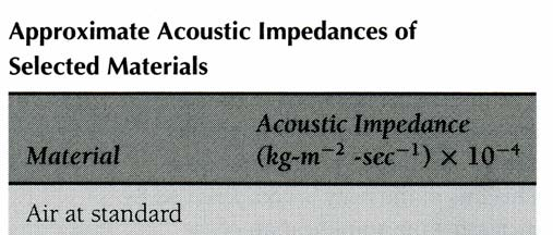
16 Reflection Reflection occurs at a boundary/interface between two adjacent tissues The difference in acoustic impedance (z) between the two tissues causes reflection of the sound wave z = density x velocity Scanhead z = 1.1 x 10 6 z = 1.7 x 10 6


17 Reflection
18 Reflection The greater the difference in acoustic impedance between two adjacent tissues, the greater the reflection If there is no difference in acoustic impedance, there is no reflection α R = ( Z ( Z Z Z 1 1 ) ) 2 2 Scanhead z = 1.1 x 10 6 z = 1.7 x 10 6
19 Reflection The greater the difference in acoustic impedence between two adjacent tissues, the greater the reflection If there is no difference in acoustic impedence, there is no reflection α T = 1 α R = 4Z1Z ( Z + Z ) 2 Scanhead z = 1.1 x 10 6 z = 1.7 x 10 6
20 Reflection Example 1: At a liver-air interface, Z 1 = 1.65 and Z 2 = (both multiplied by 10-4 with units kg/(m 2 sec). α R = (1.65 ( ) ) 2 2 = α T = 4(1.65)(0.0004) ( ) 2 = Scanhead
21 Reflection Example 2: At a muscle-liver interface, Z 1 = 1.70 and Z 2 =1.65 (both multiplied by 10-4 with units kg/(m 2 sec). α R = ( ) ( ) 2 2 = α T = 4(1.70)(1.65) ( ) 2 = Scanhead
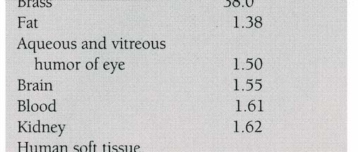
22 Reflection Reflection from a smooth tissue interface (specular) causes the sound wave to return to the scanhead The ultrasound image is formed from reflected echoes Scanhead
23 Interactions of Ultrasound with Tissue Reflection Scattering Transmission Attenuation
24 Scattering Redirection of the sound-wave in several directions Caused by interaction with a very small reflector or a very rough interface Only a portion of the sound-wave returns to the scanhead


25
26 Interactions of Ultrasound with Tissue Reflection Scattering Transmission Attenuation
27 Transmission Not all of the sound-wave is reflected, therefore some of the wave continues deeper into the body These waves will reflect from deeper tissue structures Scanhead
28 Interactions of Ultrasound with Tissue Reflection Scattering Transmission Attenuation
29 Attenuation The deeper the wave travels in the body, the weaker it becomes The amplitude/strength of the wave decreases with increasing depth
30 Ultrasound Image Formation: Pulsed Ultrasound Pulse-Echo Method Ultrasound scanhead produces pulses of ultrasound waves These waves travel within the body and interact with various organs The reflected waves return to the scanhead and are processed by the ultrasound machine An image which represents these reflections is formed on the monitor
31 Pulsed Ultrasound

32 Pulsed Ultrasound
33 Scanhead Construction
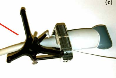
34 Scanhead Construction
35 Scanhead Construction Connector Matching Layer Damping Material Elements/Crystals
36 Scanhead Construction Matching Layer has acoustic impedance between that of tissue and the piezoelectric elements reduces the reflection of ultrasound at the scanhead surface Piezoelectric Elements produce a voltage when deformed by an applied pressure quartz, ceramics, man-made material Damping Material reduces ringing of the element helps to produce very short pulses
37 Piezoelectric Elements/Crystals Some crystals change shape (in at least one direction) with applied voltage. This is reversible: a change in dimension produces a change in voltage. The piezoelectric element/crystal produces the ultrasound pulses Electrical pulses applied to the crystal cause it to expand and contract This produces the transmitted ultrasound pulses

38 Piezoelectric Elements/Crystals
39 Piezoelectric Elements/Crystals
40 Piezoelectric Crystals and Frequency The frequency of the scanhead is determined by the thickness of the crystals Thinner elements produce HIGHER frequencies Thicker elements produce LOWER frequencies Low Frequency 3 MHz High Frequency 10 MHz

41 Piezoelectric Crystals and Frequency

42 Piezoelectric Crystals and Frequency

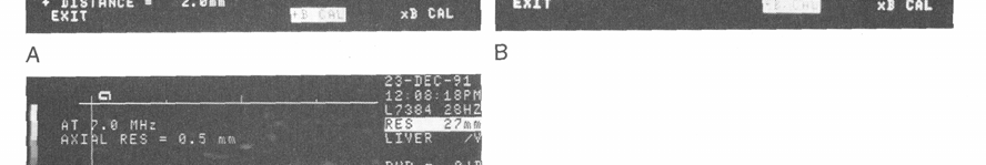
43 Human Hair Single Crystal Microscopic view of scanhead
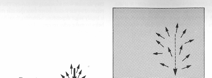
44 Frequency vs. Resolution The frequency also affects the quality of the image the higher the frequency, the shorter the wavelength the shorter the wavelength, the better the axial resolution Therefore, higher frequency scanheads produce better image resolution
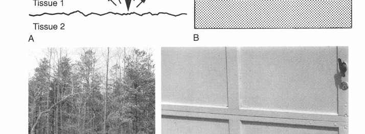
45 Frequency vs. Depth of Penetration However- The HIGHER the frequency, the LESS it can penetrate into the body The LOWER the frequency, the DEEPER the penetration This is the challenge of ultrasound imaging!!
46 Frequency vs. Depth of Penetration
47 Therefore- High frequency scanheads have the best resolution, but the least amount of penetration (e.g. L10-5) Lower frequency scanheads provide more penetration, but poorer resolution (e.g.c4-2)
48 Damping
49 Damping No damping With damping
50 Bandwidth Bandwidth is the range of frequencies emitted by the scanhead Each crystal emits a spectrum of frequencies 5MHz 7.5 MHz 10 MHz
51 Bandwidth A broadband scanhead is one which uses the entire frequency bandwidth to form the image A narrowband scanhead uses only a portion of the frequency range to form the image
52 The Returning Echo Reflected echoes return to the scanhead where the piezoelectric elements convert the ultrasound wave back into an electrical signal The electrical signal is then processed by the ultrasound system Returning Echoes
53 Goal of an Ultrasound System The ultimate goal of any ultrasound system is to make like tissues look alike and unlike tissues look different
54 Accomplishing this goal depends upon... Resolving capability of the system axial/lateral resolution spatial resolution contrast resolution temporal resolution Beamformation send and receive Processing Power ability to capture, preserve and display the information
55 Types of Resolution Axial Resolution specifies how close together two objects can be along the axis of the beam, yet still be detected as two separate objects wavelength affects axial resolution


56 Axial Resolution Types of Resolution
57 Types of Resolution Lateral Resolution the ability to resolve two adjacent objects that are perpendicular to the beam axis as separate objects Beam width affects lateral resolution
58 Types of Resolution Spatial Resolution also called Detail Resolution the combination of AXIAL and LATERAL resolution some companies may use this term
59 Types of Resolution Contrast Resolution the ability to resolve two adjacent objects of different intensity/reflective properties as separate objects
60 Types of Resolution Temporal Resolution the ability to distinguish very rapid events in sequence also known as frame rate
61 Near and Far Zones
62 Near and Far Zones Near Zone: is also called Fresnel Zone Length of Fresnel Zone = (Radius of the transducer) 2 /wavelength Far Zone: is also called Fraunhofer Zone
63 Near and Far Zones
64 Near and Far Zones
65 Near and Far Zones Sin ( θ ) = 0.6 (wavelength)/(radius of the transducer)
66 Near and Far Zones Rules for Transducer Design: The near-field length increases with increasing frequency Beam divergence in the far field decreases with increasing frequency For a given transducer frequency: The near-field length increases with increasing transducer diameter. Beam divergence in the far field decreases with increasing transducer diameter.
67 Focusing Curved Element Lens Phasing
68 Linear/Cuved Arrays
69 Linear Phased Arrays Fact #1: If an echo comes from a point source, it propagates as a spherical wave. Cross-section hit different time. Fact #2: By introducing a delay in firing & receiving signals, a plane wave can be steered.
70 Linear Phased Arrays By introducing a delay in firing & receiving signals, a plane wave can be steered.
71 Electronic Focusing
72 Multiple Focusing Frame rate is reduced
73 Variable Aperture
74 Components of an Ultrasound System Digital Broadband Beamformer RF Sig. Proc. Module Cineloop Memory Scanhead Echo Detect. Module Doppler Module Scan Convert Module M-mode Module Video Video Bus Bus Color Flow Module Video Output Module Display Control Control Bus Bus System CPU Acquisition Acquisition Signal Signal Proc. Proc. Display Display Control Control
75 Components of an Ultrasound System The BEAMFORMER is the ultrasound engine It coordinates and processes all the signals to and from the scanhead elements It is the main component responsible for image formation Digital Broadband Beamformer Scanhead
76 Components of an Ultrasound System As the US passes through tissue, it attenuates and loses strength. There are many unpredictable parameters that affect this attenuation, such as the patient, tissues, coupling, and the pathology. The simplest way is to use Time-Gain Compensation (TGC). This is also called depth-gain compensation (DGC). Assuming that US propagates at 1540 m/s, machines allow the operator to compensate (amplify) the signal by varying a weight (gain).
77 Components of an Ultrasound System How is this done? Simple machines have 3 circular dials (knobs): Initial gain Final gain Slope Additional controls may be used to set the time which the gains switch.
78 How is the image formed on the monitor? The strength or amplitude of each reflected wave is represented by a dot The position of the dot represents the depth from which the returning echo was received The brightness of the dot represents the strength of the returning echo These dots are combined to form a complete image
79 Image Display Position of Reflected Echoes Display screen divided into a matrix of PIXELS (picture elements)
80 Image Display Position of Reflected Echoes How does the system know the depth of the reflection? TIMING The system calculates how long it takes for the echo to return to the scanhead The velocity in tissue is assumed constant at 1540m/sec Velocity = Distance x Time 2
81 Strength of Reflected Echoes Strong Reflections = White dots Diaphragm, gallstones, bone Weaker Reflections = Grey dots Most solid organs, thick fluid No Reflections = Black dots Fluid within a cyst, urine, blood

82
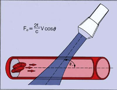
83 Other modes used with 2D Imaging DOPPLER is used to hear and measure blood flow COLOR or CPA (Color Power Angio) is added to visualize blood flow
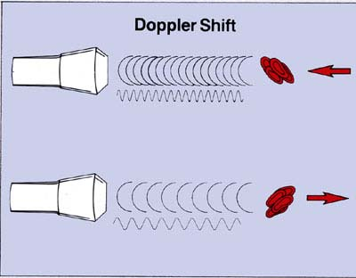
84 Doppler
85 Doppler

86 Doppler

87 Doppler

88 Doppler

89 Doppler

90 Color Doppler
Describing Sound Waves. Period. Frequency. Parameters used to completely characterize a sound wave. Chapter 3. Period Frequency Amplitude Power
 Parameters used to completely characterize a sound wave Describing Sound Waves Chapter 3 Period Frequency Amplitude Power Intensity Speed Wave Length Period Defined as the time it take one wave vibrate
BIOMEDICAL ULTRASOUND
 BIOMEDICAL ULTRASOUND Goals: To become familiar with: Ultrasound wave Wave propagation and Scattering Mechanisms of Tissue Damage Biomedical Ultrasound Transducers Biomedical Ultrasound Imaging Ultrasonic
Hunting Bats. Diagnostic Ultrasound. Ultrasound Real-time modality
 Diagnostik Ultrasound Basic physics, image reconstruction and signal processing Per Åke Olofsson Dpt of Biomedical Engineering, Malmö University Hospital, Sweden Ultrasound Real-time modality 17-WEEK FETAL
Introduction to acoustic imaging
 Introduction to acoustic imaging Contents 1 Propagation of acoustic waves 3 1.1 Wave types.......................................... 3 1.2 Mathematical formulation.................................. 4 1.3
Ultrasound Physics. ASCeXAM Review- 2011. Sidney K. Edelman, Ph.D. Director, ESP Ultrasound [email protected] 281-292-9400 www.esp-inc.
 chapter 1 Ultrasound Physics ASCeXAM Review- 2011 Sidney K. Edelman, Ph.D. Director, ESP Ultrasound [email protected] 281-292-9400 www.esp-inc.com Definitions Sound A type of wave that carries energy
BASIC PHYSICAL PRINCIPLES OF ULTRASOUND
 BASIC PHYSICAL PRINCIPLES OF ULTRASOUND BASIC PHYSICAL PRINCIPLES OF ULTRASOUND INTRODUCTION C ompetent performance of an ultrasound examination of any type is reliant on an understanding of the basic
Advancements in High Frequency, High Resolution Acoustic Micro Imaging for Thin Silicon Applications
 Advancements in High Frequency, High Resolution Acoustic Micro Imaging for Thin Silicon Applications Janet E. Semmens Sonoscan, Inc. 2149 E. Pratt Boulevard Elk Grove Village, IL 60007 USA Phone: (847)
FXA 2008. UNIT G485 Module 4 5.4.3 Ultrasound. Candidates should be able to :
 1 Candidates should be able to : ULTRASOUND Describe the properties of ultrasound. ULTRASOUND is any sound wave having a frequency greater than the upper frequency limit of human hearing (20 khz). Describe
Ultrasound. Sound waves
 Ultrasound Basic Idea Send waves into body which are reflected at the interfaces between tissue Return time of the waves tells us of the depth of the reflecting surface History First practical application,
Ultrasonic Wave Propagation Review
 Ultrasonic Wave Propagation Review Presented by: Sami El-Ali 1 1. Introduction Ultrasonic refers to any study or application of sound waves that are higher frequency than the human audible range. Ultrasonic
Acousto-optic modulator
 1 of 3 Acousto-optic modulator F An acousto-optic modulator (AOM), also called a Bragg cell, uses the acousto-optic effect to diffract and shift the frequency of light using sound waves (usually at radio-frequency).
TISSUE MIMICKING GEL QUALITY LE PHANTOM SERIES DESIGN. performance the ultrasound labs ofand. icking material has the same attenuation mim-
 QUALITY Tissue Benefits Mimicking of s RMI recognized RMI as the ultrasound standard phantoms for quality are performance the ultrasound labs ofand hospitals, manufacturers. clinics Sophisticated and ultrasound
Acoustic GHz-Microscopy: Potential, Challenges and Applications
 Acoustic GHz-Microscopy: Potential, Challenges and Applications A Joint Development of PVA TePLa Analytical Systems GmbH and Fraunhofer IWM-Halle Dr. Sebastian Brand (Ph.D.) Fraunhofer CAM Fraunhofer Institute
A pulse is a collection of cycles that travel together. the cycles ( on or transmit time), and. the dead time ( off or receive time)
, and. the dead time ( off or receive time)") chapter 2 Pulsed Ultrasound In diagnostic ultrasound imaging, short bursts, or pulses, of acoustic energy are used to create anatomic images. Continuous wave sound cannot create anatomic images. Analogy
chapter 2 Pulsed Ultrasound In diagnostic ultrasound imaging, short bursts, or pulses, of acoustic energy are used to create anatomic images. Continuous wave sound cannot create anatomic images. Analogy
Doppler. Doppler. Doppler shift. Doppler Frequency. Doppler shift. Doppler shift. Chapter 19
 Doppler Doppler Chapter 19 A moving train with a trumpet player holding the same tone for a very long time travels from your left to your right. The tone changes relative the motion of you (receiver) and
physics 1/12/2016 Chapter 20 Lecture Chapter 20 Traveling Waves
 Chapter 20 Lecture physics FOR SCIENTISTS AND ENGINEERS a strategic approach THIRD EDITION randall d. knight Chapter 20 Traveling Waves Chapter Goal: To learn the basic properties of traveling waves. Slide
AUDIO. 1. An audio signal is an representation of a sound. a. Acoustical b. Environmental c. Aesthetic d. Electrical
 Essentials of the AV Industry Pretest Not sure if you need to take Essentials? Do you think you know the basics of Audio Visual? Take this quick assessment test on Audio, Visual, and Systems to find out!
Scanning Acoustic Microscopy Training
 Scanning Acoustic Microscopy Training This presentation and images are copyrighted by Sonix, Inc. They may not be copied, reproduced, modified, published, uploaded, posted, transmitted, or distributed
Synthetic Sensing: Proximity / Distance Sensors
 Synthetic Sensing: Proximity / Distance Sensors MediaRobotics Lab, February 2010 Proximity detection is dependent on the object of interest. One size does not fit all For non-contact distance measurement,
Basics of Ultrasound Imaging
 2 Basics of Ultrasound Imaging Vincent Chan and Anahi Perlas Introduction... Basic Principles of B-Mode US... Generation of Ultrasound Pulses... Ultrasound Wavelength and Frequency... Ultrasound Tissue
APPLICATION NOTE ULTRASONIC CERAMIC TRANSDUCERS
 APPLICATION NOTE ULTRASONIC CERAMIC TRANSDUCERS Selection and use of Ultrasonic Ceramic Transducers The purpose of this application note is to aid the user in the selection and application of the Ultrasonic
Experiment 5. Lasers and laser mode structure
 Northeastern University, PHYS5318 Spring 2014, 1 1. Introduction Experiment 5. Lasers and laser mode structure The laser is a very important optical tool that has found widespread use in science and industry,
APPLICATION NOTE AP050830
 APPLICATION NOTE AP050830 Selection and use of Ultrasonic Ceramic Transducers Pro-Wave Electronics Corp. E-mail: [email protected] URL: http://www.prowave.com.tw The purpose of this application note
Physical Science Study Guide Unit 7 Wave properties and behaviors, electromagnetic spectrum, Doppler Effect
 Objectives: PS-7.1 Physical Science Study Guide Unit 7 Wave properties and behaviors, electromagnetic spectrum, Doppler Effect Illustrate ways that the energy of waves is transferred by interaction with
Acoustic Terms, Definitions and General Information
 Acoustic Terms, Definitions and General Information Authored by: Daniel Ziobroski Acoustic Engineer Environmental and Acoustic Engineering GE Energy Charles Powers Program Manager Environmental and Acoustic
Spectrum Level and Band Level
 Spectrum Level and Band Level ntensity, ntensity Level, and ntensity Spectrum Level As a review, earlier we talked about the intensity of a sound wave. We related the intensity of a sound wave to the acoustic
Waves Sound and Light
 Waves Sound and Light r2 c:\files\courses\1710\spr12\wavetrans.doc Ron Robertson The Nature of Waves Waves are a type of energy transmission that results from a periodic disturbance (vibration). They are
Waves - Transverse and Longitudinal Waves
 Waves - Transverse and Longitudinal Waves wave may be defined as a periodic disturbance in a medium that carries energy from one point to another. ll waves require a source and a medium of propagation.
Module 13 : Measurements on Fiber Optic Systems
 Module 13 : Measurements on Fiber Optic Systems Lecture : Measurements on Fiber Optic Systems Objectives In this lecture you will learn the following Measurements on Fiber Optic Systems Attenuation (Loss)
Noise. CIH Review PDC March 2012
 Noise CIH Review PDC March 2012 Learning Objectives Understand the concept of the decibel, decibel determination, decibel addition, and weighting Know the characteristics of frequency that are relevant
Various Technics of Liquids and Solids Level Measurements. (Part 3)
") (Part 3) In part one of this series of articles, level measurement using a floating system was discusses and the instruments were recommended for each application. In the second part of these articles,
(Part 3) In part one of this series of articles, level measurement using a floating system was discusses and the instruments were recommended for each application. In the second part of these articles,
T = 1 f. Phase. Measure of relative position in time within a single period of a signal For a periodic signal f(t), phase is fractional part t p
, phase is fractional part t p") Data Transmission Concepts and terminology Transmission terminology Transmission from transmitter to receiver goes over some transmission medium using electromagnetic waves Guided media. Waves are guided
Data Transmission Concepts and terminology Transmission terminology Transmission from transmitter to receiver goes over some transmission medium using electromagnetic waves Guided media. Waves are guided
DOING PHYSICS WITH MATLAB COMPUTATIONAL OPTICS RAYLEIGH-SOMMERFELD DIFFRACTION INTEGRAL OF THE FIRST KIND
 DOING PHYSICS WITH MATLAB COMPUTATIONAL OPTICS RAYLEIGH-SOMMERFELD DIFFRACTION INTEGRAL OF THE FIRST KIND THE THREE-DIMENSIONAL DISTRIBUTION OF THE RADIANT FLUX DENSITY AT THE FOCUS OF A CONVERGENCE BEAM
Acoustics: the study of sound waves
 Acoustics: the study of sound waves Sound is the phenomenon we experience when our ears are excited by vibrations in the gas that surrounds us. As an object vibrates, it sets the surrounding air in motion,
4.4 WAVE CHARACTERISTICS 4.5 WAVE PROPERTIES HW/Study Packet
 4.4 WAVE CHARACTERISTICS 4.5 WAVE PROPERTIES HW/Study Packet Required: READ Hamper pp 115-134 SL/HL Supplemental: Cutnell and Johnson, pp 473-477, 507-513 Tsokos, pp 216-242 REMEMBER TO. Work through all
The promise of ultrasonic phased arrays and the role of modeling in specifying systems
 1 modeling in specifying systems ABSTRACT Guillaume Neau and Deborah Hopkins This article illustrates the advantages of phased-array systems and the value of modeling through several examples taken from
Optical Design Tools for Backlight Displays
 Optical Design Tools for Backlight Displays Introduction Backlights are used for compact, portable, electronic devices with flat panel Liquid Crystal Displays (LCDs) that require illumination from behind.
Engineering Sciences 151. Electromagnetic Communication Laboratory Assignment 3 Fall Term 1998-99
 Engineering Sciences 151 Electromagnetic Communication Laboratory Assignment 3 Fall Term 1998-99 WAVE PROPAGATION II: HIGH FREQUENCY SLOTTED LINE AND REFLECTOMETER MEASUREMENTS OBJECTIVES: To build greater
A Guide to Acousto-Optic Modulators
 A Guide to Acousto-Optic Modulators D. J. McCarron December 7, 2007 1 Introduction Acousto-optic modulators (AOMs) are useful devices which allow the frequency, intensity and direction of a laser beam
Data Transmission. Data Communications Model. CSE 3461 / 5461: Computer Networking & Internet Technologies. Presentation B
 CSE 3461 / 5461: Computer Networking & Internet Technologies Data Transmission Presentation B Kannan Srinivasan 08/30/2012 Data Communications Model Figure 1.2 Studying Assignment: 3.1-3.4, 4.1 Presentation
Laminar and Turbulent flow. Flow Sensors. Reynolds Number. Thermal flow Sensor. Flow and Flow rate. R = Mass Flow controllers
 Flow and Flow rate. Laminar and Turbulent flow Laminar flow: smooth, orderly and regular Mechanical sensors have inertia, which can integrate out small variations due to turbulence Turbulent flow: chaotic
HET408 Medical Imaging. The Physics of Diagnostic Ultrasound
 HET408 Medical Imaging The Physics of Diagnostic Ultrasound 1 1 Introduction All conventional diagnostic ultrasound equipment depends on the ability of ultrasound waves to reflect from tissue interfaces.
Experiment 1: SOUND. The equation used to describe a simple sinusoidal function that propagates in space is given by Y = A o sin(k(x v t))
)") Experiment 1: SOUND Introduction Sound is classified under the topic of mechanical waves. A mechanical wave is a term which refers to a displacement of elements in a medium from their equilibrium state,
Experiment 1: SOUND Introduction Sound is classified under the topic of mechanical waves. A mechanical wave is a term which refers to a displacement of elements in a medium from their equilibrium state,
STATISTICAL ANALYSIS OF ULTRASOUND ECHO FOR SKIN LESIONS CLASSIFICATION HANNA PIOTRZKOWSKA, JERZY LITNIEWSKI, ELŻBIETA SZYMAŃSKA *, ANDRZEJ NOWICKI
 STATISTICAL ANALYSIS OF ULTRASOUND ECHO FOR SKIN LESIONS CLASSIFICATION HANNA PIOTRZKOWSKA, JERZY LITNIEWSKI, ELŻBIETA SZYMAŃSKA *, ANDRZEJ NOWICKI Institute of Fundamental Technological Research, Department
v = fλ PROGRESSIVE WAVES 1 Candidates should be able to :
 PROGRESSIVE WAVES 1 Candidates should be able to : Describe and distinguish between progressive longitudinal and transverse waves. With the exception of electromagnetic waves, which do not need a material
DESIGN AND EVALUATION OF PROBE WITH THREE DEGREE- OF-FREEDOM FOR NON-DESTRUCTIVE TEST USING THREE- DIMENSIONAL FINITE ELEMENT METHOD
 DESIGN AND EVALUATION OF PROBE WITH THREE DEGREE- OF-FREEDOM FOR NON-DESTRUCTIVE TEST USING THREE- DIMENSIONAL FINITE ELEMENT METHOD Masafumi Aoyanagi Graduate School of Systems and Information Engineering,
Antenna Properties and their impact on Wireless System Performance. Dr. Steven R. Best. Cushcraft Corporation 48 Perimeter Road Manchester, NH 03013
 Antenna Properties and their impact on Wireless System Performance Dr. Steven R. Best Cushcraft Corporation 48 Perimeter Road Manchester, NH 03013 Phone (603) 627-7877 FAX: (603) 627-1764 Email: [email protected]
Optical Fibres. Introduction. Safety precautions. For your safety. For the safety of the apparatus
 Please do not remove this manual from from the lab. It is available at www.cm.ph.bham.ac.uk/y2lab Optics Introduction Optical fibres are widely used for transmitting data at high speeds. In this experiment,
Overview. What is EMR? Electromagnetic Radiation (EMR) LA502 Special Studies Remote Sensing
 LA502 Special Studies Remote Sensing") LA502 Special Studies Remote Sensing Electromagnetic Radiation (EMR) Dr. Ragab Khalil Department of Landscape Architecture Faculty of Environmental Design King AbdulAziz University Room 103 Overview What
LA502 Special Studies Remote Sensing Electromagnetic Radiation (EMR) Dr. Ragab Khalil Department of Landscape Architecture Faculty of Environmental Design King AbdulAziz University Room 103 Overview What
Dispersion diagrams of a water-loaded cylindrical shell obtained from the structural and acoustic responses of the sensor array along the shell
 Dispersion diagrams of a water-loaded cylindrical shell obtained from the structural and acoustic responses of the sensor array along the shell B.K. Jung ; J. Ryue ; C.S. Hong 3 ; W.B. Jeong ; K.K. Shin
Optical Communications
 Optical Communications Telecommunication Engineering School of Engineering University of Rome La Sapienza Rome, Italy 2005-2006 Lecture #2, May 2 2006 The Optical Communication System BLOCK DIAGRAM OF
AP1 Waves. (A) frequency (B) wavelength (C) speed (D) intensity. Answer: (A) and (D) frequency and intensity.
 frequency (B) wavelength (C) speed (D) intensity. Answer: (A) and (D) frequency and intensity.") 1. A fire truck is moving at a fairly high speed, with its siren emitting sound at a specific pitch. As the fire truck recedes from you which of the following characteristics of the sound wave from the
1. A fire truck is moving at a fairly high speed, with its siren emitting sound at a specific pitch. As the fire truck recedes from you which of the following characteristics of the sound wave from the
Electromagnetic (EM) waves. Electric and Magnetic Fields. L 30 Electricity and Magnetism [7] James Clerk Maxwell (1831-1879)
![Electromagnetic (EM) waves. Electric and Magnetic Fields. L 30 Electricity and Magnetism [7] James Clerk Maxwell (1831-1879)](/thumbs/40/20813653.jpg "Electromagnetic (EM) waves. Electric and Magnetic Fields. L 30 Electricity and Magnetism [7] James Clerk Maxwell (1831-1879)") L 30 Electricity and Magnetism [7] ELECTROMAGNETIC WAVES Faraday laid the groundwork with his discovery of electromagnetic induction Maxwell added the last piece of the puzzle Heinrich Hertz made the experimental
L 30 Electricity and Magnetism [7] ELECTROMAGNETIC WAVES Faraday laid the groundwork with his discovery of electromagnetic induction Maxwell added the last piece of the puzzle Heinrich Hertz made the experimental
THE IMPOSSIBLE DOSE HOW CAN SOMETHING SIMPLE BE SO COMPLEX? Lars Hode
 THE IMPOSSIBLE DOSE HOW CAN SOMETHING SIMPLE BE SO COMPLEX? Lars Hode Swedish Laser-Medical Society The dose is the most important parameter in laser phototherapy. At a first glance, the dose seem very
Copyright 2008 Pearson Education, Inc., publishing as Pearson Addison-Wesley.
 Chapter 20. Traveling Waves You may not realize it, but you are surrounded by waves. The waviness of a water wave is readily apparent, from the ripples on a pond to ocean waves large enough to surf. It
Lab 9: The Acousto-Optic Effect
 Lab 9: The Acousto-Optic Effect Incoming Laser Beam Travelling Acoustic Wave (longitudinal wave) O A 1st order diffracted laser beam A 1 Introduction qb d O 2qb rarefractions compressions Refer to Appendix
Selected Radio Frequency Exposure Limits
 ENVIRONMENT, SAFETY & HEALTH DIVISION Chapter 50: Non-ionizing Radiation Selected Radio Frequency Exposure Limits Product ID: 94 Revision ID: 1736 Date published: 30 June 2015 Date effective: 30 June 2015
Introduction to Optics
 Second Edition Introduction to Optics FRANK L. PEDROTTI, S.J. Marquette University Milwaukee, Wisconsin Vatican Radio, Rome LENO S. PEDROTTI Center for Occupational Research and Development Waco, Texas
GE Medical Systems Training in Partnership. Module 8: IQ: Acquisition Time
 Module 8: IQ: Acquisition Time IQ : Acquisition Time Objectives...Describe types of data acquisition modes....compute acquisition times for 2D and 3D scans. 2D Acquisitions The 2D mode acquires and reconstructs
Fiber Optics: Fiber Basics
 Photonics Technical Note # 21 Fiber Optics Fiber Optics: Fiber Basics Optical fibers are circular dielectric wave-guides that can transport optical energy and information. They have a central core surrounded
Robot Perception Continued
 Robot Perception Continued 1 Visual Perception Visual Odometry Reconstruction Recognition CS 685 11 Range Sensing strategies Active range sensors Ultrasound Laser range sensor Slides adopted from Siegwart
Principles of Medical Ultrasound. Pai-Chi Li Department of Electrical Engineering National Taiwan University
 Principles of Medical Ultrasound Pai-Chi Li Department of Electrical Engineering National Taiwan University What is Medical Ultrasound? Prevention: actions taken to avoid diseases. Diagnosis: the process
A Robust Hydrophone for HIFU Metrology
 A Robust Hydrophone for HIFU Metrology Claudio I. Zanelli, Samuel M. Howard Onda Corporation, 592 E. Weddell Drive Sunnyvale, CA, 94089 USA Abstract. The high acoustic intensities generated by HIFU systems
Building Design for Advanced Technology Instruments Sensitive to Acoustical Noise
 Building Design for Advanced Technology Instruments Sensitive to Acoustic Noise Michael Gendreau Colin Gordon & Associates Presentation Outline! High technology research and manufacturing instruments respond
After a wave passes through a medium, how does the position of that medium compare to its original position?
 Light Waves Test Question Bank Standard/Advanced Name: Question 1 (1 point) The electromagnetic waves with the highest frequencies are called A. radio waves. B. gamma rays. C. X-rays. D. visible light.
Experiment 7: Familiarization with the Network Analyzer
 Experiment 7: Familiarization with the Network Analyzer Measurements to characterize networks at high frequencies (RF and microwave frequencies) are usually done in terms of scattering parameters (S parameters).
Antennas & Propagation. CS 6710 Spring 2010 Rajmohan Rajaraman
 Antennas & Propagation CS 6710 Spring 2010 Rajmohan Rajaraman Introduction An antenna is an electrical conductor or system of conductors o Transmission - radiates electromagnetic energy into space o Reception
Development of Optical Wave Microphone Measuring Sound Waves with No Diaphragm
 Progress In Electromagnetics Research Symposium Proceedings, Taipei, March 5 8, 3 359 Development of Optical Wave Microphone Measuring Sound Waves with No Diaphragm Yoshito Sonoda, Takashi Samatsu, and
An Investigationof Non Destructive Testing of Pressure Vessel
 An Investigationof Non Destructive Testing of Pressure Vessel Mohd Abdul Wahed 1, Mohammed Farhan 2 1,2 Assistant Professor, Departmentof MechanicaL Engineering, Nsakcet,AP-500024 Abstract--Non-Destructive
CONFOCAL LASER SCANNING MICROSCOPY TUTORIAL
 CONFOCAL LASER SCANNING MICROSCOPY TUTORIAL Robert Bagnell 2006 This tutorial covers the following CLSM topics: 1) What is the optical principal behind CLSM? 2) What is the spatial resolution in X, Y,
TCOM 370 NOTES 99-4 BANDWIDTH, FREQUENCY RESPONSE, AND CAPACITY OF COMMUNICATION LINKS
 TCOM 370 NOTES 99-4 BANDWIDTH, FREQUENCY RESPONSE, AND CAPACITY OF COMMUNICATION LINKS 1. Bandwidth: The bandwidth of a communication link, or in general any system, was loosely defined as the width of
PLEASE DO NOT WRITE ON THE TEST. PLACE ALL MULTIPLE CHOICE ANSWERS ON THE SCANTRON. (THANK YOU FOR SAVING A TREE.)
") PLEASE DO NOT WRITE ON THE TEST. PLACE ALL MULTIPLE CHOICE ANSWERS ON THE SCANTRON. (THANK YOU FOR SAVING A TREE.) Sound Waves Test -- each multiple choice question is worth 3 points. 1. Sound waves are
PLEASE DO NOT WRITE ON THE TEST. PLACE ALL MULTIPLE CHOICE ANSWERS ON THE SCANTRON. (THANK YOU FOR SAVING A TREE.) Sound Waves Test -- each multiple choice question is worth 3 points. 1. Sound waves are
Lab Exercise 1: Acoustic Waves
 Lab Exercise 1: Acoustic Waves Contents 1-1 PRE-LAB ASSIGNMENT................. 2 1-3.1 Spreading Factor: Spherical Waves........ 2 1-3.2 Interference In 3-D................. 3 1-4 EQUIPMENT........................
E190Q Lecture 5 Autonomous Robot Navigation
 E190Q Lecture 5 Autonomous Robot Navigation Instructor: Chris Clark Semester: Spring 2014 1 Figures courtesy of Siegwart & Nourbakhsh Control Structures Planning Based Control Prior Knowledge Operator
Sound Pressure Measurement
 Objectives: Sound Pressure Measurement 1. Become familiar with hardware and techniques to measure sound pressure 2. Measure the sound level of various sizes of fan modules 3. Calculate the signal-to-noise
18 Q0 a speed of 45.0 m/s away from a moving car. If the car is 8 Q0 moving towards the ambulance with a speed of 15.0 m/s, what Q0 frequency does a
 First Major T-042 1 A transverse sinusoidal wave is traveling on a string with a 17 speed of 300 m/s. If the wave has a frequency of 100 Hz, what 9 is the phase difference between two particles on the
AS COMPETITION PAPER 2008
 AS COMPETITION PAPER 28 Name School Town & County Total Mark/5 Time Allowed: One hour Attempt as many questions as you can. Write your answers on this question paper. Marks allocated for each question
Waves and Sound. AP Physics B
 Waves and Sound AP Physics B What is a wave A WAVE is a vibration or disturbance in space. A MEDIUM is the substance that all SOUND WAVES travel through and need to have in order to move. Two types of
1) The time for one cycle of a periodic process is called the A) wavelength. B) period. C) frequency. D) amplitude.
 The time for one cycle of a periodic process is called the A) wavelength. B) period. C) frequency. D) amplitude.") practice wave test.. Name Use the text to make use of any equations you might need (e.g., to determine the velocity of waves in a given material) MULTIPLE CHOICE. Choose the one alternative that best completes
practice wave test.. Name Use the text to make use of any equations you might need (e.g., to determine the velocity of waves in a given material) MULTIPLE CHOICE. Choose the one alternative that best completes
APPLICATION NOTES POWER DIVIDERS. Things to consider
 Internet Copy Rev A Overview Various RF applications require power to be distributed among various paths. The simplest way this can be done is by using a power splitter/divider. Power dividers are reciprocal
Handbook on the Ultrasonic Examination. Austenitic Welds
 Handbook on the Ultrasonic Examination Austenitic Welds The International Institute of Welding Edition Handbook On the Ultrasonic Examination of Austenitic Welds Compiled by COMMISSION V Testing, Measurement,
Department of Electrical and Computer Engineering Ben-Gurion University of the Negev. LAB 1 - Introduction to USRP
 Department of Electrical and Computer Engineering Ben-Gurion University of the Negev LAB 1 - Introduction to USRP - 1-1 Introduction In this lab you will use software reconfigurable RF hardware from National
Ch 25 Chapter Review Q & A s
 Ch 25 Chapter Review Q & A s a. a wiggle in time is called? b. a wiggle in space & time is called? a. vibration b. wave What is the period of a pendulum? The period is the time for 1 cycle (back & forth)
RICHARD T ELL ASSOCIATES,INC.
 RICHARD T ELL ASSOCIATES,INC. An Evaluation of Test Measurement Data Obtained on the KW-Gard RF Protective Suit March 30, 1998 Prepared for Euclid Garment Manufacturing Company 333 Martinel Drive Kent,
v = λ f this is the Golden Rule for waves transverse & longitudinal waves Harmonic waves The golden rule for waves Example: wave on a string Review
 L 23 Vibrations and Waves [3] resonance clocks pendulum springs harmonic motion mechanical waves sound waves golden rule for waves musical instruments The Doppler effect Doppler radar radar guns Review
Two primary advantages of radars: all-weather and day /night imaging
 Lecture 0 Principles of active remote sensing: Radars. Objectives: 1. Radar basics. Main types of radars.. Basic antenna parameters. Required reading: G: 8.1, p.401-40 dditional/advanced reading: Online
7.2.4 Seismic velocity, attenuation and rock properties
 7.2.4 Seismic velocity, attenuation and rock properties Rock properties that affect seismic velocity Porosity Lithification Pressure Fluid saturation Velocity in unconsolidated near surface soils (the
Antonio Rampoldi Struttura Complessa di Radiologia Interventistica Azienda Ospedale Niguarda Ca Granda, Milano. Terminology
 Biophysical principles and clinical applications of MRgFUS Alberto Torresin Struttura Complessa di Fisica Sanitaria Azienda, Milano Università degli Studi di Milano Dip. di Fisica Antonio Rampoldi Struttura
Treasure Hunt. Lecture 2 How does Light Interact with the Environment? EMR Principles and Properties. EMR and Remote Sensing
 Lecture 2 How does Light Interact with the Environment? Treasure Hunt Find and scan all 11 QR codes Choose one to watch / read in detail Post the key points as a reaction to http://www.scoop.it/t/env202-502-w2
The Conversion Technology Experts. Fiber Optics Basics
 The Conversion Technology Experts Fiber Optics Basics Introduction Fiber optic technology is simply the use of light to transmit data. The general use of fiber optics did not begin until the 1970s. Robert
AP Physics B Ch. 23 and Ch. 24 Geometric Optics and Wave Nature of Light
 AP Physics B Ch. 23 and Ch. 24 Geometric Optics and Wave Nature of Light Name: Period: Date: MULTIPLE CHOICE. Choose the one alternative that best completes the statement or answers the question. 1) Reflection,
Lesson 11. Luis Anchordoqui. Physics 168. Tuesday, December 8, 15
 Lesson 11 Physics 168 1 Oscillations and Waves 2 Simple harmonic motion If an object vibrates or oscillates back and forth over same path each cycle taking same amount of time motion is called periodic
RF Measurements Using a Modular Digitizer
 RF Measurements Using a Modular Digitizer Modern modular digitizers, like the Spectrum M4i series PCIe digitizers, offer greater bandwidth and higher resolution at any given bandwidth than ever before.
PHYS 222 Spring 2012 Final Exam. Closed books, notes, etc. No electronic device except a calculator.
 PHYS 222 Spring 2012 Final Exam Closed books, notes, etc. No electronic device except a calculator. NAME: (all questions with equal weight) 1. If the distance between two point charges is tripled, the
Antenna Deployment Technical Brief
 ProCurve Networking Antenna Deployment Technical Brief Introduction... 2 Antenna types... 2 Omni directional antennas... 2 Directional antennas... 2 Diversity antennas... 3 High gain directional antennas...
1. You stand two feet away from a plane mirror. How far is it from you to your image? a. 2.0 ft c. 4.0 ft b. 3.0 ft d. 5.0 ft
 Lenses and Mirrors 1. You stand two feet away from a plane mirror. How far is it from you to your image? a. 2.0 ft c. 4.0 ft b. 3.0 ft d. 5.0 ft 2. Which of the following best describes the image from
A wave lab inside a coaxial cable
 INSTITUTE OF PHYSICS PUBLISHING Eur. J. Phys. 25 (2004) 581 591 EUROPEAN JOURNAL OF PHYSICS PII: S0143-0807(04)76273-X A wave lab inside a coaxial cable JoãoMSerra,MiguelCBrito,JMaiaAlves and A M Vallera
Avaya WLAN 9100 External Antennas for use with the WAO-9122 Access Point
 Avaya WLAN 9100 External Antennas for use with the WAO-9122 Access Point Overview To optimize the overall performance of a WLAN in an outdoor deployment it is important to understand how to maximize coverage
Determination of source parameters from seismic spectra
 Topic Determination of source parameters from seismic spectra Authors Michael Baumbach, and Peter Bormann (formerly GeoForschungsZentrum Potsdam, Telegrafenberg, D-14473 Potsdam, Germany); E-mail: [email protected]
Understanding SWR by Example
 Understanding SWR by Example Take the mystery and mystique out of standing wave ratio. Darrin Walraven, K5DVW It sometimes seems that one of the most mysterious creatures in the world of Amateur Radio