Battery Wall Controller. Manual
|
|
|
- Moris Gaines
- 8 years ago
- Views:
Transcription
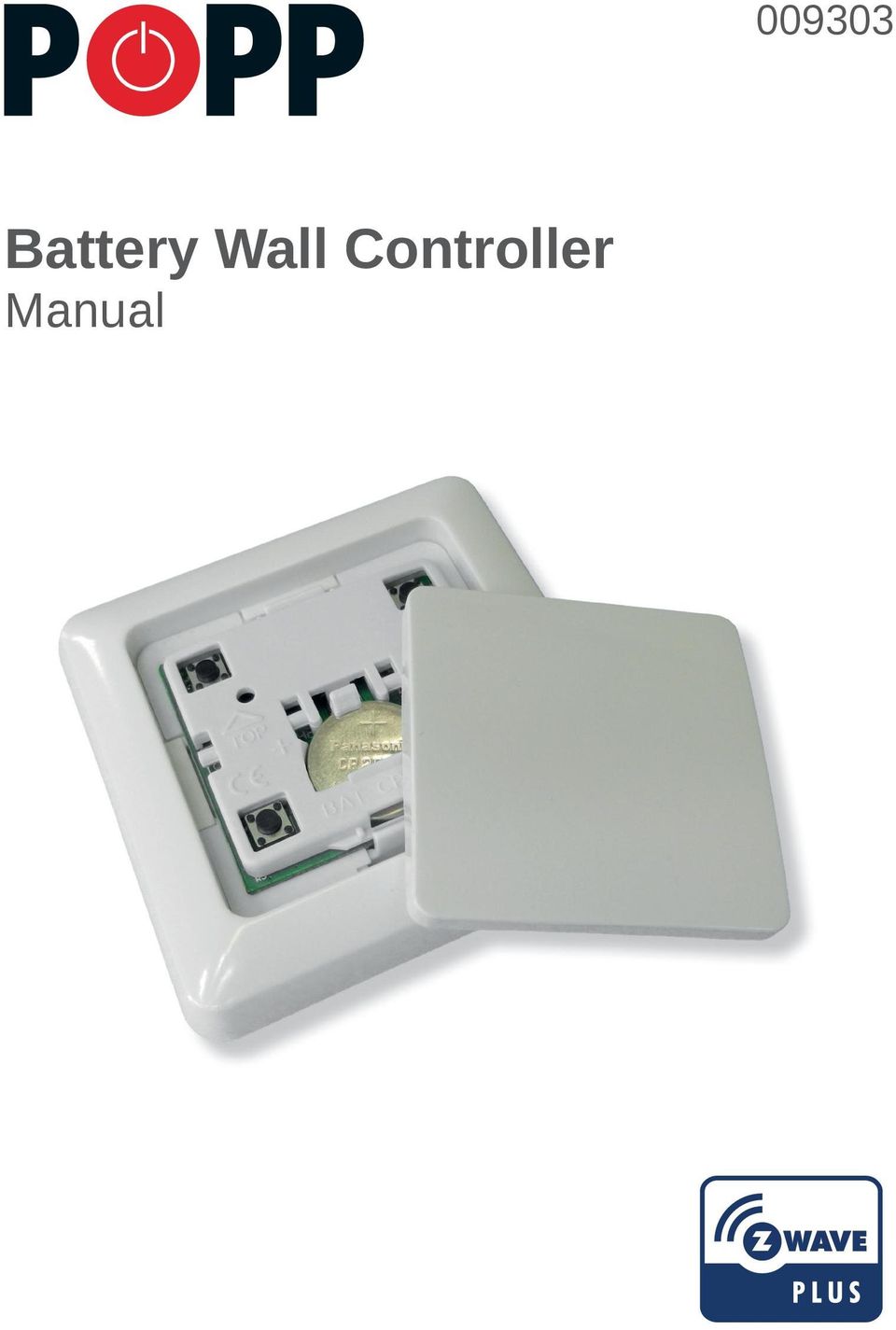
1 Battery Wall Controller Manual
2 Battery Wall Controller Manual Quick Start... 2 Product Description... 3 Installation Guidelines... 3 Behavior within the Z-Wave Network... 4 Operating the Device... 5 Child Protection... 6 Wake Up Intervals How to communicate with the device... 6 Node Information Frame... 7 LED Control... 7 Associations... 7 Set and Unset Associations to Actuators... 7 Special Functions as Z-Wave Controller... 7 Configuration Parameters... 8 Command Classes Technical Data Explanation of Z-Wave specific Terms Disposal Guidelines Support Quick Start This remote control has two modes: Normal operation for daily use Management mode for setup Pushing all four buttons for 1 sec. turns the device into management mode (indicated by slow blinking green LED). Management mode time-out is 10 sec. In factory default mode pushing one of the four buttons for 1 sec will start different inclusion modes: Button 1: Include (add) Wall Controller as secondary controller Button 2: Include (add) Wall Controller as secondary controller non secure Button 3: Include (add) new device into Wall Controller network Button 4: Include (add) new device into Wall Controller network non secure The processes for button 1 and 2 is indicated with fast red/green blinking, the processes for button 3 and 4 shows a fast green blinking. Every button push stops the process. This fast inclusion only works when device is in factory default. Once one device is included or the Wall Controller is included as secondary controller further inclusion and exclusion operation require to turn the device into management mode: Button 1: Include or exclude the device as secondary controller Button 2: Issue Wake Up Notification and send out Node Information Frame Button 3 followed by short click on button 1: Start secure inclusion Button 3 followed by short click on button 2: Start unsecure inclusion Button 3 followed by short click on button 3: Start exclusion Button 3 followed by short click on button 4: Start primary handover 2

3 as secondary secure as primary secure* Include * If included device supports security as secondary normal as primary normal Attention: For convenience reasons some special short cut apply IF and only and only IF the Wall Controller is the primary controller of the network. The first device included into a button group will define the commands sent out by this group regardless of the default value of the configuration parameters If the device is a door lock the button group will turn into door lock control (value=7). For dimmers and motor controls the value changes into Multilevel Switch Control (value=1). All other devices will turn the button group into Basic Control (value=2). All configuration values can be changed if needed. When the Wall Controller is primary controller the very first device included will be automatically put into button group A and the command set will change according to the rules just mentioned. All other devices need to be put in button groups manually. Product Description The wireless Wall Controller is a 4 button Z-Wave device capable to act both as primary or secondary controller. The four buttons can control other Z-Wave devices such as switches, dimmer and even door locks directly. Various options configurable by Z-Wave configuration commands define the actions and the commands used for this control. It is possible to use two sets of buttons (one for on/open/up and one for off/closed/down) or four single buttons to control four different groups of devices. The controller also allows triggering scenes in a central controller. Again different modes can be configured to adapt to the various implementations of scenes in different central controllers in the market. Control options also include special modes like all on/off or always controlling the Z-Wave device in proximity to the controller. The device supports secure communication when included with enhanced security option and when communicating to a device also supporting enhanced security option. Otherwise the device will automatically turn into normal communication to maintain backward compatibility. Installation Guidelines The device comes ready to use with a battery already installed. Just pull the plastic strip to activate the device. The device can be mounted on every dry and flat surface using either screws or double side adhesive. First the mounting base is fixed on the wall. Next step the switch frame is placed on the 2 frame and the electronic insert is used to fi x the frame to the mounting base as shown on the image. Finally the switching paddle(s) are mounted on the electronic base. For battery change, the switching paddle(s) need to be removed. The CR battery can be replaced by pushing the little nipple above the battery. The old battery will slide out and the new battery is inserted until the nipple will hold it again. The device can be operated in two different modes: Operation mode: This is the mode where the device is controlling other devices. Management Mode: The device is turned into the management mode by pushing all four buttons for one second. A blinking LED indicates the management mode. In the management mode buttons of the device have different functions. If no further action is performed the device will turn back to the normal mode after 10 seconds. Any management action terminates the management mode as well. In management mode the following actions can be performed: Button 1 Inclusion/Exclusion: Every inclusion or exclusion attempt is confirmed by hitting this button. Single click is used for standard inclusion and exclusion, double click is used for network wide inclusion. With this operation the device can be included into a Z-Wave network from any physical location in the network. This requires a primary controller supporting network wide inclusion. This mode lasts for 20 seconds and stops automatically. Any button press stops the mode as well. Button 2: Sends Node Information Frame and Wake Up Notification (see explanation below). Button 3: Activates the primary controller management menu. The following sub menu items are available: 3
. For dimmers and motor controls the value changes into Multilevel Switch Control (value=1).")
4 Button 3 followed by short click on button 1: Start Secure Inclusion (Add) Button 3 followed by short click on button 2: Start Unsecure Inclusion (Add) Button 3 followed by short click on button 3: Start Exclusion (Remove) Button 3 followed by short click on button 4: Start Primary Handover Button 3 followed by pushing button 4 for 5 seconds: Factory Default Reset. After clicking on button 3 keep button 4 pushed for 4 seconds. Button 4: Enters into association mode to assign target devices to one of the four associations. Refer to the manual s section about association for more information how to set and unset association groups. In factory default mode pushing one of the four buttons for 1 second will start different inclusion modes: Button 1: Include Wall Controller as secondary controller Button 2: Include Wall Controller as secondary controller non secure Button 3: Include new device into Wall Controller network Button 4: Include new device into Wall Controller network non secure The process for button 1 and 2 is indicated with fast red/green blinking, the process for button 3 and 4 shows a fast green blinking. Every button push stops the process. This fast inclusion only works when device is in factory default. as secondary Group A secure as primary Group C secure* Include * If included device supports security as secondary normal as primary normal Attention: For convenience reasons some special short cut apply IF and only IF the Wall Controller is the primary controller of the network: The first device included into a button group will define the commands sent out by this group regardless of the default value of the configuration parameters If the device is a door lock the button group will turn into door lock control (value=7). For dimmers and motor controls the value changes into Multilevel Switch Control (value=1). All other devices will turn the button group into Basic Control (value=2). All configuration values can be changed if needed. When the Wall Controller is primary controller the very first device included will be automatically put into button group A and the command set will change according to the rules just mentioned. All other devices need to be put in button groups manually. Factory Reset The device can be set back to factory defaults without performing an exclusion process. Please execute the following steps: 1. Turn the device into management mode 2. Click on button 3 3. Keep button 4 pushed for 10 seconds. For first 5 seconds the green LED will blink, then it turns into longred/short-green blinking until reset is complete. Please use this procedure only if the device is secondary controller and the primary controller is missing or otherwise inoperable. Behavior within the Z-Wave Network On factory default the device does not belong to any Z-Wave network. The device needs to join an existing wireless network to communicate with the devices of this network. This process is called Inclusion. Devices can also leave a network. This process is called Exclusion. Both processes are initiated by the primary controller of the Z-Wave network. This controller will be turned into exclusion respective inclusion mode. Please refer to your primary controller s manual on how to turn your controller into inclusion or exclusion mode. Only if the primary controller is in inclusion or exclusion mode, this device can join or leave the network. Leaving the network i.e. being excluded sets the device back to factory default. If the device already belongs to a network, follow the exclusion process before including it in your network. Otherwise inclusion of this device will fail. If the controller being included was a primary controller, it has to be reset first. Please check the instructions in the quick start section how to include and exclude the device from a network. 4

5 Operating the Device Depending on the button mode and operating modes configured using the configuration parameters the Wall Controller can be used in different ways. Button Modes Parameter define what to send to the groups Group A Group B 4 Groups are controlled with single button (parameter 1/2 = 0) The four buttons 1-4 control one single control group each: 1 A, 2 B, 3 C, 4 D. Single click turns devices in the control group on, double click turns them off. Click and hold can be used for dimming. Group C Group D 2 Groups are controlled with two buttons (parameter 1/2 = 1) Group A ON Group B ON Group C ON Group D ON The buttons 1 and 3 control the control group A (button 1 turns on, button 3 turns off), the buttons 2 and 4 control the control group B (button 2 turns on, button 4 turns off). In case dimmers are controlled, holding down the larger button will dim up, holding down the smaller button will dim down the load. Releasing the button will stop the dimming function. Group A/C ON Single clicks operate A or B Double clicks operate C or D Group B/D ON 4 Groups are controlled with two buttons and double click (parameter 1/2 = 2) Group A/C OFF Group B/D OFF This mode enhances the previous mode and allows to control two further control groups C and D using double clicks. The devices supports 8 different operating modes this means the kind of commands sent out when pushing a button. Operating modes either directly control other devices or they issue various scene activation commands to a central controller. The device supports 8 different operating modes this means the kind of commands sent out when pushing a button. Operating modes either directly control other devices or they issue various scene activation commands to a central controller. Operating modes for direct device control are: Direct control of associated devices with On/Off/Dim commands (parameter = 1). Devices are controlled using Basic Set On/Off commands and Switch-Multilevel Dim Start/Stop. This mode implements communication pattern 7. Direct control of associated devices with only On/Off commands (parameter = 2). Devices are controlled using only Basic Set On/Off commands. On dimming Up event On is sent, on dimming Down Off is sent. This mode also implements communication pattern 7. Switch-All commands (parameter = 3). In this mode all neighboring devices will receive Switch-All set On/Off command and interpret it according to their membership in Switch-All groups. This mode implements communication pattern 7. Direct control of devices in proximity (parameter = 6). Basic Set and Switch-Multilevel Dim commands are sent to a device in proximity ( cm) from the controller. Attention: In case there are more than one Z- Wave devices nearby all these devices may be switched. For this reason the proximity function should be handled with care. This mode implements communication pattern 7. Door lock control (parameter = 7). This mode allows direct control (open/close) of electronic door locks using secure communication. The mode implements communication pattern 7. 5
 Group A ON Group B ON Group C ON Group D ON The buttons 1 and 3 control the control group A (button 1 turns on, button 3")
6 Operating modes for scene activation are: Direct activation of preconfigured scenes (parameter = 5). Associated devices in an association group are controlled by individual commands defined by Z-Wave command class Scene Controller Configuration. This mode enhances mode direct control of associated devices with On/Off/Dim commands and implements communication patterns 6 and 7. Please turn the button mode to separate to allow different a scene ID on every button. Scene activation in IP gateway (parameter = 4). If configured correctly the buttons can trigger a scene in a gateway. The scene number triggered is a combination of the group number and the action performed on the button and has always two digits. The group number defines the upper digit of the scene number, the action the lower digit. The following actions are possible: 1 On 2 = Off 3 = Dim Up Start 4 = Dim Down Start 5 = Dim Up Stop 6 = Dim Down Stop Example: Clicking/double clicking the button will issue scene triggers, scene 11 (button 1 click, event on), scene 12 (button double click 1, event off, single button control is used in this example) Activation of central scenes (parameter = 8, default). Z-Wave Plus introduces a new process for scene activation the central scene control. Pushing a button and releasing a button send a certain command to the central controller using the lifeline association group. This allows reacting both on button push and button release. This mode implements communication patterns 6 but requires a central gateway supporting Z-Wave Plus. Child Protection The device can be turned into a child protection mode. In this mode all local operation is disabled. The child protection mode MUST be turned on wirelessly. However in protected by sequence mode it is possible to unlock the device for local operation by pressing any button within 5 seconds. The unlock-state will last for 5 seconds. Wake Up Intervals How to communicate with the device This device is battery operated and turned into deep sleep state most of the time to save battery life time. Communication with the device is limited. In order to communicate with the device, a static controller C is needed in the network. This controller will maintain a mailbox for the battery operated devices and store commands that can t be received during deep sleep state. Without such a controller, communication may become impossible and/or the battery life time is significantly decreased. This device will wake up regularly and announce the wake up state by sending out a so-called Wake Up Notification. The controller can then empty the mailbox. Therefore, the device needs to be configured with the desired wake up interval and the node ID of the controller. If the device was included by a static controller this controller will usually perform all necessary configurations. The wake up interval is a tradeoff between maximal battery life time and the desired responses of the device. The device will stay awake right after inclusion for 10 seconds allowing the controller to perform certain configuration. It is possible to manually wake up the device by pushing button 2 in management mode. The minimum allowed wake up time is 240s but it is strongly recommended to define a much longer interval since the only purpose of a wake up should be the reporting of the battery status or an update of the child protection settings. The device has a periodic wake up function however this function is disabled by the configuration parameter #25. This will protect the battery in case the controller is accidently configuring a wake up interval. A wake up of the Wall Controller outside the range of the controller will lead to lots of unsuccessful communication attempts draining the battery. Defining node ID of 0 as a destination of the Wake Up Notification will disable the periodical wake up function as well. It is possible to set the node ID to 255 to send Wake Up Notifications as broadcast. In this mode device takes more time to go to sleep and drains battery faster, but can notify all its direct neighbors about a wake up. 6
.")
7 Node Information Frame The Node Information Frame (NIF) is the business card of a Z-Wave device. It contains information about the device type and the technical capabilities. The inclusion and exclusion of the device are confirmed by sending out a Node Information Frame. Beside this it may be needed for certain network operations to send out a Node Information Frame. Pressing button 2 in management mode will issue a Node Information Frame. LED Control 1. Confirmation Green, 1 second 2. Failure Red, 1 second 3. Button press confirmation Green, 1/4 second 4. Waiting for Network Management Mode selection Slow green blinks 5. Waiting for group selection in Association Set Mode Green fast blink 6. Waiting for primary controller function selection Green fast blink 7. Waiting for NIF in Association Set Mode Green-red-off blink Associations Z-Wave devices control other Z-Wave devices. The relationship between one device controlling another device is called association. In order to control a different device, the controlling device needs to maintain a list of devices that will receive controlling commands. These lists are called association groups and they are always related to certain events (e.g. button pressed, sensor triggers,...). In case the event happens all devices stored in the respective association group will receive a common wireless command. Association groups functions 1 Lifeline (max. nodes in group: 10) 2 Control Group A, controlled by button 1 or single clicks of buttons 1 and 3 (max. nodes in group: 10) 3 Control Group B, controlled by button 2 or single clicks of buttons 2 and 4 (max. nodes in group: 10) 4 Control Group C, controlled by button 3 or double clicks of buttons 1 and 3 (max. nodes in group: 10) 5 Control Group D, controlled by button 4 or double clicks of buttons 2 and 4 (max. nodes in group: 10) Set and Unset Associations to Actuators Associations can be assigned and remove either via Z-Wave commands or using the device itself. To control a Z-Wave device from the Wall Controller the node ID of this device needs to be assigned to one of the four association groups. This is a three-step process: 1. Turn the Wall Controller into management mode and hit button 4 within 10 sec. (LED is blinking green when management mode is reached). 2. Within 10 sec. push the button you like the Z-Wave actuator to be assigned with. After 10 sec. the device goes back to sleep. Single click means adding to this association group, double click means removing the node selected in step (3) from this association group. 3. Find the Z-Wave actuator you like to control by the Wall Controller. Hit the button on the device to issue a Node Information Frame within 20 sec. A common way is hitting a control button one or three times. Please consult the manual of the device to be controlled for more information how to issue a Node Information Frame. Any button press on Wall Controller at this stage will terminate the process. Special Functions as Z-Wave Controller As long as this device is not included into a Z-Wave network of a different controller it is able to manage its own Z- Wave network as primary controller. As a primary controller the device can include and exclude other devices in its own network, manage associations, and reorganize the network in case of problems. 7

8 The following controller functions are supported: Include (Add) other device in own network Communication between two Z-Wave devices only works if both belong to the same wireless network. Joining a network is called inclusion and is initiated by a controller. The controller needs to be turned into the inclusion mode. Once in this inclusion mode the other device needs to confirm the inclusion typically by pressing a button. For Inclusion of Z-Wave devices into the own network the following two things have to be considered: In factory-default state only: Hit button 3 (secure) or button 4 (normal) to turn the controller into inclusion status. Consult the manual of the new device how to start the inclusion process. Always: Turn into management mode by pressing all four buttons for 5 seconds. The green LED will start blinking slowly. Now hit button 3 to activate the primary controller functions. The green LED will blink faster. Now hit button 1 (secure) or button 2 (normal) to turn the controller into inclusion state. Consult the manual of the new device how to start the inclusion process. If current primary controller in your network is in special SIS mode this and any other secondary controller can also include and exclude devices. To become primary a controller have to be reset and then include a device. Exclude (Remove) device from network The primary controller can exclude (remove) devices from the Z-Wave network. During exclusion the relationship between the device and the network of this controller is terminated. No communication between the device and other devices still in the network can happen after a successful exclusion. The controller needs to be turned into the exclusion mode. Once in this exclusion mode the other device needs to confirm the exclusion typically by pressing a button. Attention: Removing a device from the network means that it is turned back into factory default status. This process can also exclude devices from its previous network. Turn into management mode by pressing all four buttons for 5 seconds. The green LED will start blinking slowly. Now hit button 3 to activate the primary controller functions. The green LED will blink faster. Now hit button 3 again to turn the controller into exclusion status. Consult the manual of the new device how to start the exclusion process. Shift primary role to a different controller The device can hand over its primary role to another controller and become secondary controller. Turn into management mode by pressing all four buttons for 5 seconds. The green LED will start blinking slowly. Now hit button 3 to activate the primary controller functions. The green LED will blink faster. Now hit button 4 to turn the controller into primary shift mode. Consult the manual of the new device how to start the primary shift process for the new primary controller. Configuration Parameters Z-Wave products are supposed to work out of the box after inclusion, however certain configuration can adapt the function better to user needs or unlock further enhanced features. Button 1 and 3 pair mode (Number 1, Size 1) In separate mode button 1 works with Group A, button 3 with Group C. Click is ON, Hold is dimming UP, Double click is OFF, Click-Hold is dimming DOWN. In pair button 1/3 are UP/DOWN correspondingly. Click is ON/OFF, Hold is dimming UP/DOWN. Single clicks works with Group A, double click with Group C. 0 Separately 1 In pair without double clicks (default) 2 In pair with double clicks 8
 or button 4 (normal) to turn the controller")
9 Button 2 and 4 pair mode (Number 2, Size 1) In separate mode button 2 works with control group B, button 4 with control group D. Click is ON, Hold is dimming UP, Double click is OFF, Click-Hold is dimming DOWN. In pair button B/D are UP/DOWN correspondingly. Click is ON/OFF, Hold is dimming UP/DOWN. Single clicks works with Group B, double click with Group D. 0 Separately 1 In pair without double clicks (default) 2 In pair with double clicks Command to control Group A (Parameter 11, Size 1) This parameter defines the command to be sent to devices of control group A when the related button is pressed. 0 Disable 1 Switch on/off and Dim (send Basic Set and Switch Multilevel) 2 Switch on/off only (send Basic Set) 3 Switch all 4 Send scenes 5 Send preconfigured scenes 6 Control devices in proximity 7 Control door lock 8 Central scene to gateway (default) Command to control Group B (Parameter 12, Size 1) This parameter defines the command to be sent to devices of control group B when the related button is pressed. 0 Disable 1 Switch on/off and Dim (send Basic Set and Switch Multilevel) 2 Switch on/off only (send Basic Set) 3 Switch all 4 Send scenes 5 Send preconfigured scenes 6 Control devices in proximity 7 Control door lock 8 Central scene to gateway (default) Command to control Group C (Parameter 13, Size 1) This parameter defines the command to be sent to devices of control group C when the related button is pressed. 0 Disable 1 Switch on/off and Dim (send Basic Set and Switch Multilevel) 2 Switch on/off only (send Basic Set) 3 Switch all 4 Send scenes 5 Send preconfigured scenes 6 Control devices in proximity 7 Control door lock 8 Central scene to gateway (default) 9
 2 In pair with double clicks Command to control Group A (Parameter 11, Size 1) This parameter defines the command to be sent to devices of")
10 Command to control Group D (Parameter 14, Size 1) This parameter defines the command to be sent to devices of control group D when the related button is pressed. 0 Disable 1 Switch on/off and Dim (send Basic Set and Switch Multilevel) 2 Switch on/off only (send Basic Set) 3 Switch all 4 Send scenes 5 Send preconfigured scenes 6 Control devices in proximity 7 Control door lock 8 Central scene to gateway (default) Send the following switch all commands (Number 21, Size 1) 1 Switch off only (default) 2 Switch on only 255 Switch all on and off Invert buttons (Number 22, Size 1) 0 No (default) 1 Yes Blocks wake up even when Wake Up Interval is set (Number 25, Size 1) If the Wall Controller wakes up and there is no controller nearby, several unsuccessful communication attempts will drain battery. 0 Wake up is blocked (default) 1 Wake up is possible if configured accordingly Send unsolicited battery report on Wake Up (Number 30, Size 1) If the Wall Controller wakes up and there is no controller nearby, several unsuccessful communication attempts will drain battery. 0 No 1 To same node as Wake Up Notification (default) 2 Broadcast to neighbors Command Classes Supported command classes ALL SWITCH BATTERY POWERLEVEL Version 1 WAKE UP Version 2 ASSOCIATION Version 2 VERSION Version 2 SCENE CONTROLLER CONFIGURATION Version 1 MULTI CHANNEL ASSOCIATION Version 2 MULTI COMMAND ENCAPSULATED Version 1 10
 0 No (default) 1 Yes Blocks wake up even when Wake Up Interval is set (Number 25, Size 1) If the Wall Controller wakes up and there is no controller nearby, several unsuccessful")
11 CONFIGURATION Version 1 MANUFACTURER SPECIFIC Version 1 CENTRAL SCENE Version 1 SECURITY Version 1 Z-WAVE PLUS INFORMATION Version 1 DEVICE RESET LOCALLY Version 1 ASSOCIATION GROUP INFORMATION Version 1 BASIC Version 1 SCENE ACTIVATION Version 1 MULTILEVEL SWITCH Version 1 DOOR LOCK Version 1 MULTI CHANNEL Version 1 DOOR LOCK Version 1 MULTI CHANNEL Version 1 ALL SWITCH Version 1 POWERLEVEL Version 1 Controlled command classes CENTRAL SCENE Version 1 SECURITY Version 1 BASIC Version 1 SCENE ACTIVATION Version 1 MULTILEVEL SWITCH Version 1 DOOR LOCK Version 1 MULTI CHANNEL Version 1 ALL SWITCH Version 1 Technical Data IP Rating IP 20 Battery Type 1 * CR2032 Frequency MHz Wireless Range Up to 100 m outside, on average up to 20 m inside buildings Explorer Frame Support No Device Type Portable Controller Routing No FLiRS No Firmware Version 1.3 Battery Life > 2 years Explanation of Z-Wave specific Terms Controller is a Z-Wave device with capabilities to manage the network. Controllers are typically gateways, remote controls or battery operated wall controllers. Slave is a Z-Wave device without capabilities to manage the network. Slaves can be sensors, actuators and even remote controls. Primary Controller is the central organizer of the network. It must be a controller. There can be only one primary controller in a Z-Wave network. Inclusion is the process of bringing new Z-Wave devices into a network. Exclusion is the process of removing Z-Wave devices from the network. Association is a control relationship between a controlling device and a controlled device. Wake up Notification is a special wireless message issued by a Z-Wave device to announce that is able to communicate. Node Information Frame is a special wireless message issued by a Z-Wave device to announce its capabilities and functions. 11

12 Disposal Guidelines The product contains batteries. Please remove the batteries when the device is not used. Do not dispose of electrical appliances as unsorted municipal waste, use separate collection facilities. Contact your local government for information regarding the collection systems available. If electrical appliances are disposed of in landfills or dumps, hazardous substances can leak into the groundwater and get into the food chain, damaging health and well-being. Support Should you encounter any problem, please give us an opportunity to address it before returning this product. Most questions regarding Z-Wave wireless communication standard can be answered through the international community at If your question can t be answered there, please contact us by info@popp.eu 2015 POPP & Co. While the information in this manual has been compiled with great care, it may not be deemed an assurance of product characteristics. Popp & Co. shall be liable only to the degree specified in the terms of sale and delivery. The reproduction and distribution of the documentation and software supplied with this product and the use of its contents is subject to written authorization from Popp & Co. We reserve the right to make any alterations that arise as the result of technical development. Phone: +44 (0) info@popp.eu Web: 12

ZME_WALLC-S Z-Wave Secure Wall Controller
 ZME_WALLC-S Z-Wave Secure Wall Controller Firmware Version : 1.0 Quick Start S This device operates as Z-Wave sensor in two modes: the normal control mode (daily use) or in management mode for setup. Pushing
ZME_RC2 Z-Wave Remote Control
 ZME_RC2 Z-Wave Remote Control Firmware Version : 1.1 Quick Start S This device is a Z-Wave Remote Control with the logical function of a sensor. Push the "Include" button behind the slider on the back
Solar Powered Outdoor Siren Manual
 005107 Solar Powered Outdoor Siren Manual 1 Solar Powered Outdoor Siren Manual Quick Start... 2 Product Description... 2 Installation Guidelines... 3 Behavior within the Z-Wave Network... 3 Operating the
ZME_05459 Wall Blind Control Set for Busch-Jaeger DURO 2000 Firmware Version : 1.8
 ZME_05459 Wall Blind Control Set for Busch-Jaeger DURO 2000 Firmware Version : 1.8 Quick Start A This device is a Z-Wave Actuator. Triple click one of the buttons on the device will include the device.
Z-Wave.Me Wall Controller
 Z-Wave.Me Wall Controller ZME_06443: Wall Controller Firmware Version 1.1 1 General Information about Z- Wave Safe: Generally radio systems build a direct link between the transmitter and the receiver.
Please refer to the chapters below for detailed information about all aspects of the products usage.
 EUR_STELLAZ Wall Radiator Thermostat Valve Control Firmware Version : 0.4 Quick Start S This device is a wireless sensor. All operation is performed using the little button behind the round hole in the
NOQ_NQ-9121 Z-Wave Data Logger for Gas Meters Firmware Version : 2.55
 NOQ_NQ-9121 Z-Wave Data Logger for Gas Meters Firmware Version : 2.55 Quick Start S This device is a Z-Wave Sensor. Inclusion and Exclusion are confirmed by triple clicking the Z-Wave button on the device.
ST815 Illumination Sensor with LCD
 ST815 Illumination Sensor with LCD The Illumination Sensor with LCD (refer to as Illumination Sensor hereafter) is a Z-Wave TM enabled device which is fully compatible with any Z-Wave TM enabled network.
Quick start: Panic Watch EU
 Quick start: Panic Watch EU Technical specs Normal operating voltage Frequency range Wireless Range 1x CR2032 3V battery 868.42 MHz Min 150 meters in a mesh network Basic operations - The Panic Watch can
Installation and Operating Manual p. 23. Radio push button 2 channel: HM-PB-2-WM55-2
 Installation and Operating Manual p. 23 Radio push button 2 channel: HM-PB-2-WM55-2 1. English edition 10/2013 Documentation 2013 eq-3 Ltd., Hong Kong All rights reserved. No parts of this manual may be
Quick start: Energy Switch EU
 Technical specifications Normal operating voltage Quick start: Energy Switch EU 230Vac/50Hz Recommended max. load 3000W 600W Frequency range Wireless range Energy measurement 868.42 MHz 30~100 meters in
Introduction to Z-Wave. An Introductory Guide to Z-Wave Technology
 Introduction to Z-Wave An Introductory Guide to Z-Wave Technology Table of Contents Z-Wave Overview and Functionality... 3 Z-Wave Technology Quick Overview... 3 Radio Specifications... 3 Network and Topology...
POPP Hub Gateway. Manual
 POPP Hub Gateway Manual 008900 POPP Hub Gateway Manual Quick Start... 2 Hardware... 2 Smart Home User Interface... 2 Applications (Apps) realize the intelligence of your Smart Home... 3 Functions of the
Z-Way Home Automation User Interface Documentation. (c) Z-Wave.Me Team, based on Version 2.0
 Z-Wave.Me Team, based on Version 2.0") Z-Way Home Automation User Interface Documentation (c) Z-Wave.Me Team, based on Version 2.0 2 Contents 1 The Z-Way HA User Manual 5 1.1 Widgets......................................... 6 1.2 Notifications......................................
Z-Way Home Automation User Interface Documentation (c) Z-Wave.Me Team, based on Version 2.0 2 Contents 1 The Z-Way HA User Manual 5 1.1 Widgets......................................... 6 1.2 Notifications......................................
Z-Wave Gas Reader. Product Manual NQ-9121-EU. From your Z-wave network directly to the cloud! DESCRIPTION
 Product Manual NQ-9121-EU Z-Wave Gas Reader From your Z-wave network directly to the cloud! DESCRIPTION The NorthQ Gas Reader is a small device based on the Z-Wave wireless standard-ideal for home automation.
LYNX Touch Series Security Systems
 LYNX Touch Series Security Systems Home Automation Guide 800-11309 3/12 Rev. A Z-Wave Programming The LYNX Touch control features Z-Wave technology that is designed to automate devices in a home control
SYSTEM COMPONENTS. Gateway. Sensors. Repeater. 1-701-475-2361 1-888-475-2361 www.bekspyder.com. Figure 1
 Welcome to BEK SpyderProtect! This quick start guide is designed to give you a basic overview of the system, and help you get the most out of your home automation, monitoring, and alerts experience. For
ZXT-120 (Z-Wave-to-AC IR Extender) Firmware Version: V1.0 and V1.1
 Firmware Version: V1.0 and V1.1") ZXT-120 (Z-Wave-to-AC IR Extender) Firmware Version: V1.0 and V1.1 1 Table of Contents Introduction... 3 Controller and Gateway Requirements... 4 Built-in IR code library... 4 Glossary... 5 ZXT-120 Operations...
ZXT-120 (Z-Wave-to-AC IR Extender) Firmware Version: V1.0 and V1.1 1 Table of Contents Introduction... 3 Controller and Gateway Requirements... 4 Built-in IR code library... 4 Glossary... 5 ZXT-120 Operations...
Are apps available for Virtual Water Assistant? No. We use a mobile website.
 What is a battery backup unit (BBU) sump pump? A battery backup unit (BBU) sump pump is a secondary sump pump powered by a 12V deep cycle battery that automatically protects your basement if power goes
NOTE: Append this Operation IB to the Install IB to make one IB-booklet. Need a divider tab between the 2 sections. Blank page remove.
 Product Name: CT101 Document Title: CT101 Operation Guide Document Type Code: IBOE Part Number: 1202-004-002 20apr12 Iris inclusion text added mtf 9apr12 bs edits mtf 14mar12 ch edits mtf 13mar12 initial
Lynx Touch L5100 Technical Training. Z-Wave Setup
 Lynx Touch L5100 Technical Training Z-Wave Setup L5100-Z-wave Combines Home Automation and Security Controls up to: - 40 Devices (Lights, switches and lamp modules) - 3 Thermostats - 4 Door Locks Rules
KNX Gateway RGK02-5023E-01
 KNX Gateway RGK02-5023E-01 Table of contents Page 1 General Information 1.1 Technical data 5 1.2. Intended Use 6 1.3 Specifications 6 1.4 Compatibility 6 1.5 Scope of delivery 6 2 Information about the
Inwall 4 Input / 4 Output Module
 Inwall 4 Input / 4 Output Module IO44C02KNX Product Handbook Product: Inwall 4 Input / 4 Output Module Order Code: IO44C02KNX 1/27 INDEX 1. General Introduction... 3 2. Technical data... 3 2.1 Wiring Diagram...
Stove Guard Kit User Manual
 Stove Guard Kit User Manual Innohome improves the Safety of your Home. inno home www.innohome.com Stove Guard Kit User Manual Stove Guard Kit User Manual Congratulations! You now own one of the most intelligent
MAKING MODERN LIVING POSSIBLE. living connect. Installation and User Guide. Danfoss heating
 MAKING MORN LIVING POSSIBLE Danfoss heating living connect Installation and User Guide Contents 1.0 System overview... 3 2.0 Overview of display and control buttons... 3 3.0 Installation - step by step...
LED Bulb Manual. Aeotec by Aeon Labs LED Bulb.
 LED Bulb Manual Aeotec by Aeon Labs LED Bulb. Aeotec LED Bulb is a multi-coloured LED bulb which allows control (on/off/dim/colour change) via wireless Z-Wave commands. The LED Bulb can also communicate
HomeSeer Technologies. HomeSeer Technologies LLC 35 Constitution Dr, Suite C Bedford NH, 03110 www.homeseer.com
 HomeSeer Technologies HomeSeer Z-Troller Z-Wave Computer Interface Installation guide HomeSeer Technologies LLC 35 Constitution Dr, Suite C Bedford NH, 03110 www.homeseer.com Description Thank for your
Setting Up the ZigBee Ethernet Gateway
 Setting Up the ZigBee Ethernet Gateway MAN-01-00030-1.4 This manual describes how to install and set up ZigBee communication between a SolarEdge device (Inverters or Safety and Monitoring Interface) and
F453. TiF453. User guide 10/11-01 PC
 F453 TiF453 User guide 10/11-01 PC 2 TiF453 User guide Contents 1. Hardware and Software requirements 4 2. Installation 4 1.1 Minimum Hardware requirements 4 1.2 Minimum Software requirements 4 3. Fundamental
Alarm Security Kit - NVR
 Alarm Security Kit - NVR EN The alarm configuration menu (see above right screenshot) allows you to configure and change settings for the PIR movement sensors, window/door sensors, remote controls (key
Breathe. Relax. Here Are the Most Commonly Asked Questions and Concerns About Setting Up and Programming the SurroundBar 3000.
 Breathe. Relax. Here Are the Most Commonly Asked Questions and Concerns About Setting Up and Programming the SurroundBar 3000. Our Customer Service Department has compiled the most commonly asked questions
INSTRUCTION MANUAL All-In-One GSM Home Alarm System SB-SP7200-GSM
 INSTRUCTION MANUAL All-In-One GSM Home Alarm System SB-SP7200-GSM Revised: August 28, 2014 PRODUCT REFERENCE MOUNTING ACCESSORIES PIR / MOTION DETECTION UNIT MAIN UNIT POWER ADAPTER MOUNTING ACCESSORIES
AIR CONDITIONER REMOTE CONTROLLER ILLUSTRATION CS457-R14A 202055090318 20110215
 AIR CDITIER REMOTE CTROLLER ILLUSTRATI CS5-RA 005500 005 Thank you very much for purchasing our air conditioner Please read this owner's manual carefully before using your air conditioner CTENTS Handling
PhoneWatch Smart Security System User Manual - Domonial
 PW0002 10/13 Customer Support: 1850 753 753 PhoneWatch Ltd., Unit 3/4, Sandyford Park, Burton Hall Rd, Sandyford Industrial Estate, Dublin 18. Email: info@phonewatch.ie PhoneWatch Smart Security System
ImagineWorldClient Client Management Software. User s Manual. (Revision-2)
") ImagineWorldClient Client Management Software User s Manual (Revision-2) (888) 379-2666 US Toll Free (905) 336-9665 Phone (905) 336-9662 Fax www.videotransmitters.com 1 Contents 1. CMS SOFTWARE FEATURES...4
ImagineWorldClient Client Management Software User s Manual (Revision-2) (888) 379-2666 US Toll Free (905) 336-9665 Phone (905) 336-9662 Fax www.videotransmitters.com 1 Contents 1. CMS SOFTWARE FEATURES...4
Transmitter Actuator 230V wave UP 560. Operation
 Transmitter ctuator 230V wave UP 560 5WG3 560-201 Product- and pplication Description Diagram The transmitter actuator 230V wave UP 560 (Diagram ) is a flush-mounted device with radio communication for
User Manual GSM Alarm System. www.deltasecurity.cn. All rights reserved by Delta Security Co., Ltd
 User Manual GSM Alarm System All rights reserved by Delta Security Co., Ltd Dear Clients, Thank you for using our GSM Alarm System. We are committed to giving you the best home security available today
Additional Instruction
 Additional Instruction Note: a. Please connect the camera with 2.4G WIFI router or Ethernet cable, can t support 5G router. b. For first time wifi connection, please put your mobile close to camera within
4310/4320 Wireless Position Monitor Burst Configuration and Diagnostics
 Instruction Manual Supplement 4310/4320 Wireless Position Monitor 4310/4320 Wireless Position Monitor Burst Configuration and Diagnostics This document applies to: Fisher 4320 Device Type 1308 (hex) 4872
EDK 350 (868 MHz) EDK 350U (902 MHz) EnOcean Developer Kit
 EDK 350U (902 MHz) EnOcean Developer Kit") EDK 350 (868 MHz) EDK 350U (902 MHz) EnOcean Developer Kit EDK 350 User Manual Important Notes This information describes the type of component and shall not be considered as assured characteristics. No
EDK 350 (868 MHz) EDK 350U (902 MHz) EnOcean Developer Kit EDK 350 User Manual Important Notes This information describes the type of component and shall not be considered as assured characteristics. No
TUTA B12. User Manual GSM REMOTE CAMERA. Manual version 3.0
 TUTA B12 GSM REMOTE CAMERA User Manual Manual version 3.0 TUTA Series GSM Remote Camera Thank you for purchasing the TUTA camera. This camera is a remotely controlled image-capturing device consisting
Shadow TX(A) Shadow RX
 Shadow RX") Shadow TX(A) Shadow RX Asset Management and RFID Transmitter Tags Asset Management Receiver The Shadow TX(A) and Shadow RX wireless asset management system is a standalone wireless asset tracking system
Shadow TX(A) Shadow RX Asset Management and RFID Transmitter Tags Asset Management Receiver The Shadow TX(A) and Shadow RX wireless asset management system is a standalone wireless asset tracking system
Instruction manual for models:
 Instruction manual for models: Prisma+ Prisma+ ivista Cast Aluminium Electric Radiators High Performance with Intelligent Technology INCORPORATiNG HiGH-PRECiSiON ELECTRONiC CONTROL WiTH THE LATEST ENERGY
LOK-IT ENCRYPTED USB User Instructions
 LOK-IT ENCRYPTED USB User Instructions LOK-IT USB Drives are supplied by the University to safely allow a method to transport data. They are not intended to be used for primary data storage. The LOK-IT
Table of Contents. Hardware Installation...7 Push Button Security... 8. Using the Setup Wizard...10. Configuration...11 Main... 12 Security...
 Table of Contents Table of Contents Product Overview...3 Package Contents...3 System Requirements... 3 Introduction...4 Features... 4 Hardware Overview...5 LEDs... 5 Connection... 6 Hardware Installation...7
EM6556 e-domotica Mini Switch
 EM6556 e-domotica Mini Switch EM6556 e-domotica Mini Switch 2 ENGLISH Table of contents 1.0 Introduction...2 1.1 Functions and features...2 1.2 Packing contents...2 2.0 Using the mini switch...3 2.1 Use
SAS-IPCAM115 MANUAL IP CAMERA
 SAS-IPCAM115 MANUAL IP CAMERA Table of contents Introduction: Safety precautions: Packaging content: System requirements: Product description: User instructions: Maintenance: Warranty: Disclaimer: Disposal:
PRODUCT MANUAL LUMENTO X4 LED. LED Controller ZN1DI-RGBX4. Program version: 1.0 Manual edition: a
 PRODUCT MANUAL LUMENTO X4 LED LED Controller ZN1DI-RGBX4 Program version: 1.0 Manual edition: a INDEX 1. Introduction...3 1.1. Lumento X4... 3 1.2. Installation... 4 2. Configuration...6 3. ETS Parameterization...7
MAGICAR M871A. Car alarm with two-way remote User s guide
 MAGICAR M871A Car alarm with two-way remote User s guide EN MAGICAR M871A Car alarm with two-way remote User s guide TABLE OF CONTENTS Table of contents...2 1. Important notice...4 2. Introduction...4
Quick Guide. for Nikon 340.00 354.00 MHz, US FCC/IC 433.42 434.42 MHz, CE
 a MAKE IT POSSIBLE Quick Guide for Nikon 340.00 354.00 MHz, US FCC/IC 433.42 434.42 MHz, CE UPDATE FIRMWARE: Be sure ALL your PocketWizard ControlTL radios, including this one, are updated to the latest
MANUAL IP Baby and Child Monitor
 KN-BM60 MANUAL IP Baby and Child Monitor Table of contents Introduction 2 Safety precautions 2 Packaging content 2 System requirements 2 Product description 3 User instructions 3 Maintenance 23 Warranty
GENERATOR START CONTROL MODULE - MINI (2 Wire to 3 Wire)
") FEATURES & APPLICATIONS Inexpensive 2 wire to 3 wire start controller for electric start high speed gas generators. Optimized for use with Outback Invertors. Supports three types of 3 wire generator control
FEATURES & APPLICATIONS Inexpensive 2 wire to 3 wire start controller for electric start high speed gas generators. Optimized for use with Outback Invertors. Supports three types of 3 wire generator control
ALARM SYSTEM INSTALLATION GUIDE
 ALARM SYSTEM INSTALLATION GUIDE Congratulations on the purchase of your Egardia alarm system. Egardia's website www.egardia.com Customer services Please visit www.egardia.com if you would like further
Two-way communication, keep checking the commnunication between the panel and accessories, make sure the system safer.
 Innovative GSM & WIFI dual network operating platform. On WIFI network, the alarm system will work without any fee. If no WIFI, it will work on GSM automatically. With state-of-the-art WIFI network technology,
INSTALLATION MANUAL VEHICLE SECURITY SYSTEM CE-SS200
 INSTALLATION MANUAL VEHICLE SECURITY SYSTEM CE-SS200 FUSION CULTURE TABLE OF CONTENTS There s no point doing something if no one notices. We ve always believed the way to make things happen is by getting
Smart Home Monitoring Powered by Honeywell Total TM Connect Remote Services Basic User Guide
 Smart Home Monitoring Powered by Honeywell Total TM Connect Remote Services Basic User Guide With Honeywell Total Connect Remote Services, you can stay connected and in control of your home or business
User's Guide. [Home Network] app. Model No.
![User's Guide. [Home Network] app. Model No.](/thumbs/26/8329814.jpg "User's Guide. [Home Network] app. Model No.") User's Guide [Home Network] app Model No. Table of Contents Table of Contents 1 Welcome to the Panasonic Home Network System!...5 1.1 What is the Panasonic Home Network System?...5 1.2 What can I use it
User's Guide [Home Network] app Model No. Table of Contents Table of Contents 1 Welcome to the Panasonic Home Network System!...5 1.1 What is the Panasonic Home Network System?...5 1.2 What can I use it
Q-Cam Professional V 1.1 User Manual
 Q-Cam Professional V 1.1 User Manual Introduction QCam Professional is a remote monitoring application designed primarily for the remote monitoring and auxiliary control of IP video cameras. It allows
Wireless Travel Mouse with 5-Buttons User Manual
 Wireless Travel Mouse with 5-Buttons User Manual Product Features 1. Radio frequency 27MHz wireless transmission 2. Use of 256 ID codes to prevent interference between several wireless mice being used
SNMP Web card. User s Manual. Management Software for Uninterruptible Power Supply Systems
 SNMP Web card User s Manual Management Software for Uninterruptible Power Supply Systems Table of Contents 1. Overview... 3 1.1 Introduction... 3 1.2 Features... 3 1.3 Overlook... 3 1.4 Installation and
Setting Up the Cisco Unified IP Phone
 CHAPTER 3 This chapter includes the following topics, which help you install the Cisco Unified IP Phone on an IP telephony network: Before You Begin, page 3-1 Understanding the Cisco Unified IP Phone 7962G
How To Use A Power Supply On A Powerline 2.2 (Ai)
") KNX/EIB Product documentation Issue: 05.08.2010 629x1220 Push button sensor 3 comfort 1-gang Push button sensor 3 comfort 2-gang (1+1) Push button sensor 3 comfort 3-gang Push button sensor 3 comfort 4-gang
KNX/EIB Product documentation Issue: 05.08.2010 629x1220 Push button sensor 3 comfort 1-gang Push button sensor 3 comfort 2-gang (1+1) Push button sensor 3 comfort 3-gang Push button sensor 3 comfort 4-gang
AD-01 Slave Auto Dialer. Owner s Manual
 AD-01 Slave Auto Dialer Owner s Manual AD-01 Slave Manual.indd 1 10/15/2009 10:20:44 AM 2 AD-01 Slave Manual.indd 2 10/15/2009 10:20:44 AM Features: Programmable entry/exit delay time; select up to 9 (32
Keypad Programming Instructions for the Profile Series LK and v.g1.5 Locks
 Keypad Programming Instructions for the Profile Series LK and v.g1.5 Locks A7857A 1 2 3 4 5 6 Table of Contents Page LK Programming...14 Transaction Log for LK...45 G1LU, G1PK, G1TU, G1TP Programming...58
Watch Your Garden Grow
 Watch Your Garden Grow The Brinno GardenWatchCam is a low cost, light weight, weather resistant, battery operated time-lapse camera that captures the entire lifecycle of any garden season by taking photos
LIGHTCOMMANDER II 24/6 LIGHTCOMMANDER II 48/6. User s Manual
 LIGHTCOMMANDER II 24/6 LIGHTCOMMANDER II 48/6 User s Manual Version 2.59 August 2007 Table of Contents 0. Introduction... 4 0.1 How to use your Operator s Manual... 4 0.2 Specifications and Installation...
DOORKING SYSTEMS 1830 SERIES NETWORK WORKSHOP LAN APPLICATIONS ACCESS CONTROL SOLUTIONS LOCAL AREA NETWORK (LAN) CONNECTION REV 04.
 CONNECTION REV 04.") DOORKING SYSTEMS ACCESS CONTROL SOLUTIONS 1830 SERIES NETWORK WORKSHOP LAN APPLICATIONS REV 04.11 LOCAL AREA NETWORK (LAN) CONNECTION Ethernet Connection: An Ethernet Cable, or wireless connection must
DOORKING SYSTEMS ACCESS CONTROL SOLUTIONS 1830 SERIES NETWORK WORKSHOP LAN APPLICATIONS REV 04.11 LOCAL AREA NETWORK (LAN) CONNECTION Ethernet Connection: An Ethernet Cable, or wireless connection must
Energy Communication Unit (ECU)
") Altenergy Power System Energy Communication Unit (ECU) Installation and User Manual (For ECU-3 V3.8) ALTENERGY POWER SYSTEM INC. All rights reserved TABLE OF CONTENTS 1.0 Introduction... 2 2.0 Installation...
Altenergy Power System Energy Communication Unit (ECU) Installation and User Manual (For ECU-3 V3.8) ALTENERGY POWER SYSTEM INC. All rights reserved TABLE OF CONTENTS 1.0 Introduction... 2 2.0 Installation...
Mini Portable Reader (MPR) Model HS 5900L F
 Model HS 5900L F") Mini Portable Reader (MPR) Model HS 5900L F TABLE OF CONTENTS Chapter 1: Mini Portable Reader (MPR) Basics 1 1.1 Preparing for Operation 1 1.2 Installing/Changing Batteries 1 1.3 Scanning with the Mini
Mini Portable Reader (MPR) Model HS 5900L F TABLE OF CONTENTS Chapter 1: Mini Portable Reader (MPR) Basics 1 1.1 Preparing for Operation 1 1.2 Installing/Changing Batteries 1 1.3 Scanning with the Mini
INSTALLATION MANUAL XM3 Reader
 INSTALLATION MANUAL XM3 Reader Conditions Transactions, deliveries et cetera will be according to the general terms of delivery as deposited at the Chamber of Commerce at Meppel, The Netherlands. Registration
Frequently Asked Questions: Home Networking, Wireless Adapters, and Powerline Adapters for the BRAVIA Internet Video Link
 Frequently Asked Questions: Home Networking, Wireless Adapters, and Powerline Adapters for the BRAVIA Internet Video Link What is a home network? A home network is a way of connecting your BRAVIA Internet
Bluetooth Version FUZZYSCAN FAMILY. Quick Start Guide WIRELESS SCANNER
 Bluetooth Version FUZZYSCAN FAMILY Quick Start Guide WIRELESS SCANNER Getting Familiar with Your FuzzyScan Thank you for choosing Cino FuzzyScan Bluetooth Cordless Image Scanner. Powered by the combination
User Manual. NETGEAR, Inc. 350 East Plumeria Drive San Jose, CA 95134, USA. December 2014 202-11380-01
 User Manual December 2014 202-11380-01 NETGEAR, Inc. 350 East Plumeria Drive San Jose, CA 95134, USA Support For product updates and web support, visit http://support.arlo.com. Trademarks NETGEAR, Inc.
Automatic Phone-Out Home Monitoring Systems
 Automatic Phone-Out Home Monitoring Systems Power Outage and Freeze Alarm Model Number: THP202 Power Outage, Freeze and Flood Alarm Product Description Model Number: THP201 These monitoring systems are
2.1 Battery Installation 3 2.2 Powering On & Off 4 2.3 Pairing 4 2.4 Mount Installation 5
 User Manual Table of Contents 1. In the Box 3 2. Getting Started 3 2.1 Battery Installation 3 2.2 Powering On & Off 4 2.3 Pairing 4 2.4 Mount Installation 5 3. Using the ishower 2 5 3.1 Navigating Between
C-more Remote HMI App
 Topic: CM630 C-more Remote HMI App SAFETY NOTICE: The C-more Remote HMI App allows the user to connect to remote C-more panels from Ethernet, Wi-Fi, or cellular network connections. The Remote user can
EKON BMS HVAC system. Simply Smart. www.ekonhome.com. Touch Screen Controller. Going green. Wireless. Wireless Thermostat with Light Switch
 Going green EKON BMS HVAC system Wireless Thermostat with Light Switch Control Fan Coil or Central AirCon Wireless Touch Screen Controller Wireless Light or Motorized Blind Wall Switch www.ekonhome.com
Advanced User s Guide
 Advanced User s Guide 8.VIII.2012 ver. 1.02\beta Contents Contents I 1 Fibaro System - General Information 1 2 The Z-Wave Protocol 3 2.1 Device Types.............................. 3 2.2 How the network
Spylamp2 Bicycle GPS Tracker Instruction Manual
 Spylamp2 Bicycle GPS Tracker Instruction Manual Version 2.0.0.5 1 Getting Started Your GPS tracker is controlled via text message. You will need your mobile phone and a SIM card (2G) with credit on it
Communication Protocol
 Analysis of the NXT Bluetooth Communication Protocol By Sivan Toledo September 2006 The NXT supports Bluetooth communication between a program running on the NXT and a program running on some other Bluetooth
Simon XT/XTi CDMA Module V4 Installation Instructions
 Simon XT/XTi CDMA Module V4 Installation Instructions Content Contact information... 1 Introduction... 1 Compatibility... 1 Account Creation... 1 Installation... 1 Power Up... 3 CDMA Phone Test (Module
Quick Start Guide. RV 120W Wireless-N VPN Firewall. Cisco Small Business
 Quick Start Guide Cisco Small Business RV 120W Wireless-N VPN Firewall Package Contents Wireless-N VPN Firewall Ethernet Cable Power Adapter Quick Start Guide Documentation and Software on CD-ROM Welcome
Smart Anytime, Safe Anywhere. Home Passport Gateway-G Series. The Epitome of Smart Living
 Smart Anytime, Safe Anywhere Home Passport Gateway-G Series The Epitome of Smart Living Index Introduction to the HPGW-G Series 1 Features 2 The HPGW-G Comparison Chart 5 Ordering Information 6 Home Passport
site monitoring Kit Site Monitoring Kit User Manual we prove it.
 site monitoring Kit 1 User Manual Site Monitoring Kit User Manual we prove it. 2 site monitoring Kit Content 1. Introduction 3 2. Content of the Site Monitoring Kit 4 3. Preparation 6 1. Positioning of
AC750 WiFi Range Extender
 Model EX6100 User Manual April 2014 202-11307-03 350 East Plumeria Drive San Jose, CA 95134 USA Support Thank you for selecting NETGEAR products. After installing your device, locate the serial number
MANUAL FOR RX700 LR and NR
 MANUAL FOR RX700 LR and NR 2013, November 11 Revision/ updates Date, updates, and person Revision 1.2 03-12-2013, By Patrick M Affected pages, ETC ALL Content Revision/ updates... 1 Preface... 2 Technical
mysensors mysensors Wireless Sensors and Ethernet Gateway Quick Start Guide Information to Users Inside the Box mysensors Ethernet Gateway Quick Start
 mysensors Information to Users mysensors Wireless Sensors and Ethernet Gateway Quick Start Guide This equipment has been tested and found to comply with the limits for a Class B digital devices, pursuant
N600 WiFi USB Adapter
 Model WNDA3100v3 User Manual December 2014 202-11470-01 350 East Plumeria Drive San Jose, CA 95134 USA Support Thank you for selecting NETGEAR products. After installing your device, locate the serial
WPR400 Wireless Portable Reader
 P516-098 WPR400 Wireless Portable Reader User guide Para el idioma español, navegue hacia www.schlage.com/support. Pour la portion française, veuillez consulter le site www.schlage.com/support. Contents
4310/4320 Wireless Position Monitor
 Quick Start Guide Wireless Position Monitor 4310/4320 Wireless Position Monitor This document is intended to guide you through initial set up of the 4310/4320 wireless position monitor. Steps include:
Your World Made Simple.
 Your World Made Simple. In g! 6.0 ELAN introduced customer based lock code and user access management through a new User Settings Interface. The interface is a pass-code protected area that allows you
Tebis application software
 Tebis application software Input products / ON / OFF output / RF dimmer Electrical / Mechanical characteristics: see product user manual Product reference Product designation TP device RF devices WYC81xQ
Networking. General networking. Networking overview. Common home network configurations. Wired network example. Wireless network examples
 Networking General networking Networking overview A network is a collection of devices such as computers, printers, Ethernet hubs, wireless access points, and routers connected together for communication
Home Monitoring and Control service provided by Verizon Online LLC
 Home Monitoring and Control service provided by Verizon Online LLC A separate subscription to Verizon FiOS TV is required for use with FiOS TV service. About This Manual This manual is designed for online
VFS24/32HDIP. Public Display IP Monitor User Manual
 VFS24/32HDIP Public Display IP Monitor User Manual 2 Contents Before You Begin...4 Side Panel Control buttons...6 Connections...7 OSD Function...7 LCD monitor Mounting Guide...9 Getting started... 10 Power
Home Monitoring and Control service provided by Verizon Online LLC
 Home Monitoring and Control service provided by Verizon Online LLC A separate subscription to Verizon FiOS TV is required for use with FiOS TV service. About This Manual This manual is designed for online
FAQs. Conserve package. Gateway... 2 Range Extender... 3 Smart Plug... 3 Thermostat... 4 Website... 7 App and Mobile Devices... 7
 FAQs Conserve package Gateway... 2 Range Extender... 3 Smart Plug... 3 Thermostat... 4 Website... 7 App and Mobile Devices... 7 FAQs Gateway Can I have someone install my system for me? If you are concerned
CHAPTER 2: USING THE CAMERA WITH THE APP
 TABLE OF CONTENTS OVERVIEW... 1 Front of your camera... 1 Back of your camera... 2 ACCESSORIES... 3 CHAPTER 1: Navigating the Mobile Application... 4 Device List: How to Use this Page... 4 My Messages:
Prestige 202H Plus. Quick Start Guide. ISDN Internet Access Router. Version 3.40 12/2004
 Prestige 202H Plus ISDN Internet Access Router Quick Start Guide Version 3.40 12/2004 Table of Contents 1 Introducing the Prestige...3 2 Hardware Installation...4 2.1 Rear Panel...4 2.2 The Front Panel
Adding or replacing a mesh node in an existing mesh network
 Adding or replacing a mesh node in an existing mesh network Use this procedure to add or replace a in an existing mesh For this procedure to work all nodes running the same firmware version. Before you