Advanced User s Guide
|
|
|
- Molly Alisha Gibson
- 8 years ago
- Views:
Transcription

1 Advanced User s Guide 8.VIII.2012 ver. 1.02\beta

2
3 Contents Contents I 1 Fibaro System - General Information 1 2 The Z-Wave Protocol Device Types How the network works Routing Principles Fibaro System Modules Fibaro Dimmer FGD Product Characteristics Specifications Example Configuration Parameters Associations Tips and Tricks Wiring Diagrams - Dimmer Relay Switch 2x1,5kW FGS Product Characteristics Specifications Example Configuration Parameters Associations Tips and Tricks Relay Switch 1x3kW FGS Product Characteristics Specifications Example Configuration Parameters Associations Wiring diagrams - Relay Switch 1x3,0kW Roller Shutter FGR I

4 II CONTENTS Product Characteristics Specifications Roller Shutter Calibration Example Configuration Parameters Associations Connecting Scheme - Roller Shutter Dimmer Bypass FGB Specifications Connecting Scheme - Bypass Wireless Z-Wave Sensors Universal Binary Sensor Specifications Example Configuration Parameters Universal Binary Sensor - Inclusion / Exclusion Wiring Diagrams - Universal Binary Sensor Danfoss Living Connect Electronic Thermostat Specifications Danfoss Thermostat Inclusion/Exclusion Adapters Motion Sensor Specifications Everspring Motion Sensor Inclusion/Exclusion Flood Sensor Specifications Everspring Flood Sensor Inclusion/Exclusion Temperature and Humidity Sensor Specifications Everspring Temp./Humidity sensor Inclusion/Exclusion Door / Window Sensor Specifications Aeon Labs D/W Sensor Inclusion/Exclusion Smoke Detector Specifications Smoke Sensor Inclusion/Exclusion Home Center HC2 Finder Your House Rooms Devices Z-Wave Devices Inclusion

5 CONTENTS III IP Camera Inclusion Creating Virtual Devices Deleting Devices Scenes Example Scenes Linked Devices Linked Devices - Heating Linked Devices - Air Conditioning Linked Devices - Humidity Video Gate Panels SMS Panel Alarm Panel Heating Panel Heating Panel Humidity Panel History Panel Access Control Notifications Panel Localization Panel Configuration General LAN Settings Location Backup Recovery Mode List of Figures 93

6

7 Chapter 1 Fibaro System - General Information Fibaro is a wireless, intelligent building automation system, based on the Z-Wave communication protocol. Thanks to MESH network topology, Fibaro has certain advantages over competitive solutions, which establish a direct connection between the signals emitter and receiver. In such a situation the radio signal is weakened by any obstacle in its way - walls, furniture etc. Each Fibaro System component serves as a signal emitter and receiver, plus also as a signal repeater. This is the main advantage of the Fibaro System - if establishing a direct connection between devices proves impossible, a connection may be established thanks to the other devices serving as a signal repeaters. The Fibaro System uses two-way communication between system components. Communications are sent to devices and the devices send back communication confirming the signal s reception. This way each device reports its current state, so that it may be easily determined if a certain action has been performed. Data transmission security in the Fibaro System is comparable to that of wired home automation systems. Fibaro System uses a Z-Wave certified data transmission radio frequency - e.g. 868,4 MHz in EU. Each individual network gets its own, unique identification number (home ID) which gives the possibility for two or more independent Fibaro Systems to operate in the same building without any interference. Z-Wave wireless communication serves as a certified standard, which assures compatibility for products produced by various manufacturers all over the world. Thanks to that approach Z-Wave technology offers great potential for expansion and further development. Because Z-Wave intelligent systems work in Mesh topology, where each device (node) serves as a transmitter and receiver. Each device (node) also reports it 1


8 2 CHAPTER 1. FIBARO SYSTEM - GENERAL INFORMATION state, which enables the central unit to constantly monitor the networks status. Thanks to this technology the Fibaro System creates a dynamic network in which the function and location of each device is constantly monitored, in real time, from the moment the System is started. Fibaro System modules serve as network nodes. Thanks to Mesh topology, each node not only sends and receives the radio signals, but also serves as a relay for other nodes, i.e. nodes collaborate to propagate the data within the network. Each time nodes change their location, or one of the nodes dies, the network reconfigures itself automatically. This way the Fibaro System devices communicate with each other even in the event of central unit failure, e.g. in case of fire, flooding, etc. Each of the Fibaro System modules are tested and certified for compatibility by the Z-Wave technology owner.

9 Chapter 2 The Z-Wave Protocol The Z-Wave protocol uses 868,4 MHz radio frequency in Europe, 908,4 MHz in USA and in AUS/NZ on unlicensed ISM bands. The protocol was launched with 9600 b/s data transmission but it has been raised to 40Kbps. Both versions of the protocol are compatible. Data is transmitted in 8bit blocks, in which the most important bit is always sent first. Each Z-Wave network has its unique ID called HOME ID. In addition, each device gets its own ID - Node ID. Each, newly added device gets two ID numbers - HOME ID and Node ID. Home ID is the same for all devices within the network, while Node ID is unique for a given node. If another controller (secondary master) is added to the network, it gets the same HOME ID as the main controller. 2.1 Device Types There are two types of devices in the Z-Wave protocol: Master and Slave. There are two types of master devices: Primary and Secondary. There is always one Primary Master Controller in each Z-Wave network, to manage devices inclusion/exclusion and preserve network settings. Secondary Master Controllers copy this data from the Primary Master Controller. In the Fibaro System, the Primary Master Controller is the Home Center 2. The Secondary Master (secondary) -e.g. remote, or any other device bearing Secondary Master s characteristic. Controllers initiate data transmission within the network. Slaves are devices serving as actors i.e. they perform tasks directed by Master Devices. 3

10 4 CHAPTER 2. THE Z-WAVE PROTOCOL 2.2 How the network works Managing network nodes is realized through two types of operation: including/excluding nodes and associating nodes. Including device to the network means creating a new network node, while excluding device means deleting network node. Each Z-Wave network has one Primary Master Controller, able to include/exclude devices (create/delete network node). Other controllers (Secondary Master Controllers) copy the informations from the Primary Master. Adding/deleting node always starts with entering the Primary Master Controller into learning mode and then by activating the device s inclusion. The latter is done by the switch connected to the device, a specially designated switch in the device, or simply by clicking an icon in the system menu (Primary Master Controller s users interface). Once the primary master controller receives information from a new node, the node receives a Home ID (same for each node within the network) and its unique Node ID. Association is a direct link between network nodes, realised without any action from Primary Master Controller. 2.3 Routing Principles In a typical wireless network the central controller has a direct wireless connection to all of the other networking nodes. This always requires a direct radio link. In case of disturbances the controller does not have any backup route to reach the nodes. However, Z-Wave is a wireless system that offers a very powerful mechanism to overcome this limitation. Z-Wave nodes can forward and repeat messages that are not in direct range of the controller. This gives greater flexibility as Z-Wave allows communication, even though there is no direct wireless connection or if a connection is temporarily not available, due to some change in the room or building. Z-Wave is able to route messages via up to four repeating nodes. This is a compromise between the network size and stability, and the maximum time a message is allowed to travel in the network. Every node is able to determine which nodes are in its direct wireless range. These nodes are called neighbours. During inclusion and later on request, the node is able to inform the controller about its list of neighbours. Using this information, the controller is able to build a table that has all the information about possible communication routes in a network. The user can access the routing table. There are several software solutions, typically called installer tools, which visualise the routing table to optimize the network setup. A controller will always try first to transmit its message directly to the destination. If this is not possible it will use its routing table to find the next best way to the destination. The controller can select up to three alternative routes and will try to send the message via these routes. Only
 copy the informations from the Primary Master.")
11 2.3. ROUTING PRINCIPLES 5 if all three routes fail (the controller does not receive an acknowledgement from the destination) the controller will report a failure.
 the controller will report")
12

13 Chapter 3 Fibaro System Modules 3.1 Fibaro Dimmer FGD211 Figure 3.1: Dimmer module, FGD-211 Radio controlled light dimming module, designed to work with light sources of any type. May be connected to two-wire or three-wire electric installation (with or without neutral wire). Fibaro Dimmer can switch or dim connected light source either through radio waves or through the wall switch connected directly to it. Automatically senses connected device, features automatic overload protection switch-off and soft start function. Works as a dimmer or as a connector, with two-wire or three-wire installations. In case of fluorescent light sources or certain transformers, only on/off function may be possible Product Characteristics As at light dimmer it operates under the following loads: 7

14 8 CHAPTER 3. FIBARO SYSTEM MODULES Conventional incandescent Halogen 230V Low voltage halogen 12V (with electronic transformers) Dimmable LED When used with FGB001 it may operate with any dimmable load up to 500W* Moreover, as an electronic switch it may work with: Compact fluorescent lamps LED bulbs Fluorescent lamps with electronic ballast and the majority of conventional ballasts When used with FGB001 it may operate with any dimmable load up to 500W Specifications Power supply: 230V ±10%, 50Hz, Output Power: W (for resistive loads - 230V); W (for resistive loads - 110V), Dimmer type: Leading-edge dimmer In accordance with EU standards: EN (noise) EN (operational safety), AS/NZS 3100 (general requirements for electrical products) Overcurrent protection: 2,5A, Circuit temperature limits: 105 C, Ambient temperature: from 10 to 40 C, For installation in boxes: 50mm, Radio protocol : Z-Wave, Radio Frequency: 868,4 MHz for EU; 908,4 MHz for US; 921,4 MHz for AUS/NZ/BRA, Range: up to 50 m outdoors; up to 30 m indoors (depending on building materials),

 shows following parameters: Device name Room - parameter available from the list of rooms created (see 5.")
15 3.1. FIBARO DIMMER FGD211 9 Dimensions (H x W x D): 15 x 42 x 36 mm. Electricity consumption: 0,8W Figure 3.2: Dimmers Configuration Window Dimmers configuration window (HC2 interface) shows following parameters: Device name Room - parameter available from the list of rooms created (see 5.3 for detailed description, Device kind Device type ID - Devices number, Node ID - Unique devices number within Z-Wave network, EndPointID - Multichannel devices number, Controlled device - Parameter taken from available devices list, Show Slave Devices Power Output

16 10 CHAPTER 3. FIBARO SYSTEM MODULES Example Configuration Parameters Configuration parameters, for each module are available in the Advanced Settings tab, for each device, in the Home Center 2 interface. Parameter 8 % change assigned to one step (automatic operation). Default setting: 1% Parameter 9 Time to switch between min. / max. dimm level at manual operation. Default setting: 0.05s Parameter 10 Time to switch between max. / min. dimm level at remote operation. 0 turns off smooth dimming level change. WARNING inductive and capacitive devices must be set to 0 to work properly (fluorescent lamps, electric motors). Parameter 12 Max. dimming level. Default setting: 99% Parameter 13 Min. dimming level. Default setting: 2% WARNING! Max level must be always higher then min. NOTE In case of fluorescent lights or non-dimmable LEDs the max. dimming level must be set at 98%; min at 99%. If settings are too low when AC powered motors are used, operation may result in motor failure. Parameter 14 Wall Switch type - mono-stable (press switch) or bi-stable Default setting: mono-stable. Parameter 15 Double Click ON / OFF. Default setting: ON(double click = lights set to 100%) Parameter 17 Stair switch function On / Off Stair Switch Off. WARNING! Dimmer works with two bi-stable switches or infinite number of mono-stable switches.
. Parameter 12 Max. dimming level. Default setting: 99% Parameter 13 Min. dimming level. Default setting: 2% WARNING!")
17 3.1. FIBARO DIMMER FGD Parameter 18 Synchronize Dim level for associated devices On / Off. Default setting: OFF Associations Association lets a Dimmer trigger other Z-Wave devices, e.g. another Dimmer, Relay Switch, Roller Shutter. Triggering is performed in direct communication between devices, without contacting the Primary Master Controller (Home Center 2). A Dimmer may associate with up to 16 ordinary devices or up to 7 multichannel devices per association group, from which 1 device is always a network controller. Recommended number of devices per association The more devices are associated, the longer time will take for association action to take effect on each associated device. Dimmer supports two association groups - I and II: I association group is designated for Switch Key no.1, II association group is designated for Switch Key no.2. NOTE The following parameter refers to II association group: Parameter 7 GET Device State before sending steering frame assigned to key no.2. Default Setting: GET frame sent, device state checked before sending association command.

18 12 CHAPTER 3. FIBARO SYSTEM MODULES Tips and Tricks 1. How to include a Dimmer module connected to fluorescent lamp? To include a Dimmer connected to fluorescent lamp, please connect the module and fluorescent lamp observing wiring diagram (operating manual), connect power input and double click button B or key switch connected to S1 input. Fluorescent lamp should turn ON (Dimmer turns ON with full power). Next, complete inclusion process as described in the operating manual. 2. How to set parameters for fluorescent lamp? Parameter 10: 0 seconds, Parameter 13: 98% 3. What kind of dimming does the Fibaro Dimmer provides? The Fibaro Dimmer is a Leading-Edge type dimmer. The module is compatible with universal transformers and those designed for leading-edge type dimming (inclining sinusoid curve).


19 3.1. FIBARO DIMMER FGD Wiring Diagrams - Dimmer 1. Before beginning, please make sure power supply is disconnected. 2. Connect Dimmer observing wiring diagram shown below. 3. Insert Dimmer and wall switch into connecting box. 4. While completing point 3. please take special care to lay antenna wire properly. Symbols description: L - live wire, N - neutral wire, O - Dimmer output, Sx - power for Switch connected to the Dimmer, S1 - switch key 1 (also, enters Dimmer module into learning mode, see. inclusion process), S2 - switch key 2, B - service key (used for including/excluding device, see S1). Figure 3.3: Dimmer wiring diagram

20 14 CHAPTER 3. FIBARO SYSTEM MODULES Figure 3.4: Dimmer wiring diagram - 2-wire connection Figure 3.5: Dimmer wiring diagram - 3-wire connection

21 3.1. FIBARO DIMMER FGD Figure 3.6: Dimmer wiring diagram - 3 way connection Figure 3.7: Dimmer wiring diagram - 4-way connection
22 16 CHAPTER 3. FIBARO SYSTEM MODULES 3.2 Relay Switch 2x1,5kW FGS211 Figure 3.8: Relay Switch 2x1,5kW module, FGS-221 The radio controlled Fibaro Double On/Off Relay Switch is designed to be installed in standard wall switch boxes, or anywhere else where it is necessary to operate two independent devices of 1,5kW power output each. The Fibaro Double On/Off Relay Switch can switch connected devices on or off either through radio waves or through the wall switch connected directly to it Product Characteristics Controlled by FIBARO system devices or any Z-Wave controller. Microprocessor control. Executive elements: relays. The device may be operated by mono-stable (press switch) and bi-stable push-buttons Specifications Power supply: V ±10% 50/60Hz, Maximum load current for single AC output: 8A / 230V 50/60Hz*, Maximum load current for single DC output: 8A / 30V*, Output circuit power (resistive load-230v): 2 x 1,5 kw*, Comply with standards: EN 55015; EN , AS/NZS 3100 Temperature limits: 105 C, Operational temperature: from 0 to 40 C,
23 3.2. RELAY SWITCH 2X1,5KW FGS For installation in boxes: 50mm, Radio protocol: Z-Wave, Radio Frequency: 868 MHz for EU; 908 MHz for US; 921 MHz for AUS/NZ/BRA Range: up to 50 m outdoors, up to 30 m indoors (depending on building materials), Dimensions (H x W x D) 15 x 42 x 38 mm. Electricity consumption: 0,8W * In case of load other than resistive, pay attention to the value of cosφ and if necessary apply load lower than the rated load. Figure 3.9: Relay Switch 2x1,5kW configuration window Relay Switch 2x1,5kW configuration window (HC2 interface) shows the following parameters: Devices name Room - Parameter available from the list of rooms created (see 5.3 for detailed description) Device kind Devices type ID - Devices number Node ID - Unique devices number within Z-Wave network,
24 18 CHAPTER 3. FIBARO SYSTEM MODULES EndPointID - Multichannel devices number Controlled Device - Parameter taken from available devices list Show Slave Devices Show Slave Devices Power Output Example Configuration Parameters Configuration parameters for each module are available in the Advanced Settings tab for each device in he Home Center 2 interface. Parameter 3 Relay Auto OFF after specified time. Default Setting: Auto OFF disabled. Parameter 4 & 5 Relay 1 / 2 Auto OFF after specified time. Default Setting: 0,2s Parameter 13 State Change (ON / OFF) for bistable switch (Parameter no.14). Default Setting: key position change = ON or OFF. Parameter 14 Switch Type - mono-stable (press switch) or bistable. Default Setting: monostable. Parameter 15 Operating associated Dimmer / Roller Shutter, enable / disable. Default Setting: disable. (If enabled, hold or double click given key to trigger associated Dimmer / Roller Shutter). Parameter 16 Device On / Off after power cut. Default setting - OFF Associations Association lets Relay Switch 2x1,5kW trigger other Z-Wave devices, e.g. Dimmer, another Relay Switch, Roller Shutter, or a scene (only involving Home Center 2). Triggering is performed in direct communication between devices, without contacting the Home Center 2 (except for the use as a scene triggering device).
25 3.2. RELAY SWITCH 2X1,5KW FGS Relay Switch 2x1,5kW may associate with up to 16 ordinary devices or up to 7 multi channel devices per association group, from which 1 device is always a network controller. Recommended number of devices per association The more devices that are associated, the longer it will take for association action to take effect on each associated device. Relay Switch 2x1,5kW supports two association groups - I and II: I association group is designated for Switch Key no.1, II association group is designated for Switch Key no Tips and Tricks 1. What is the minimum powering voltage? Relay Switch 2x1,5kW may be powered by 24V DC current. 2. May I connect two different Live wires - one for the module, another one for the device triggered by the module? Yes, a Relay Switch 2x1,5kW may be connected to two independent circuits at the same time - one powering the module, another one (even powered by a different voltage) powering the circuit triggered by the module. 3. May I use Relay Switch 2x1,5kW in two and three wire electrical systems, just like the Dimmer? The Relay Switch 2x1,5kW is designed to work on three-wire electrical system only, i.e. it needs the Neutral wire. 4. I would like to use two Relay Switch 2x1,5kW modules to control home alarm control unit, but it is powered by 12V current. In such a case another circuit, powering the Relay Switches (with 24V at least) will be necessary (see p. 2) 5. Can I use the Relay Switch modules to operate floor heating? Yes. These modules may be used to operate both electrical and hydraulic floor heating systems, in such use the modules will be used to turn electric valves ON or OFF. Heating itself will be programmed in the Heating Panel in of the HC2. For monitoring temperature we recommended the use of a DS18B20 sensor, together with a Fibaro Universal Binary Sensor. Wiring Diagrams - Relay Switch 2x1,5kW 1. Before beginning, please make sure power supply is disconnected. 2. Connect Relay Switch 2x1,5kW observing wiring diagram shown below.
26 20 CHAPTER 3. FIBARO SYSTEM MODULES 3. Insert Relay Switch 2x1,5kW and wall switch into connecting box. 4. While completing point 3. please take special care to lay antenna wire properly. Symbol descriptions - Relay Switch 2x1.5kW : N - Neutral wire L - Live wire I - Output device power in O1 - Output 1 O2 - Output 2 S1 - Switch key 1 (also, enters the module into learning mode, see. inclusion process) S2 - Switch key 2 B - Service key (used for including/excluding device, see S1) Figure 3.10: Single switch, Relay Switch 2x1,5kW connection diagram
27 3.2. RELAY SWITCH 2X1,5KW FGS Figure 3.11: Single switch with an alternative power supply for the load Figure 3.12: Double switch, Relay Switch 2x1,5kW connection diagram
28 22 CHAPTER 3. FIBARO SYSTEM MODULES Figure 3.13: Double switch with an alternative power supply for the load
29 3.3. RELAY SWITCH 1X3KW FGS Relay Switch 1x3kW FGS211 Figure 3.14: Relay Switch 1x3kW module, FGS-211 Radio controlled Fibaro Double On/Off Relay Switch is designed to be installed in standard wall switch boxes, or anywhere else where it is necessary to operate one single device of 3,0kW power output. Fibaro Double On/Off Relay Switch can switch connected device on or off either through radio waves or through the wall switch connected directly to it Product Characteristics Controlled by FIBARO system devices or any Z-Wave controller. Microprocessor control. Executive elements: relays. The device may be operated by mono-stable (press-switch) and bi-stable push-buttons Specifications Power supply: V ±10% 50/60Hz, Maximum load current for single AC output: 8A / 230V 50/60Hz*, Maximum load current for single DC output: 8A / 30V*, Output circuit power (resistive load-230v): 2 x 1,5 kw*, Comply with standards: EN 55015; EN , AS/NZS 3100 Temperature limits: 105 C, Operational temperature: from 0 to 40 C,

30 24 CHAPTER 3. FIBARO SYSTEM MODULES For installation in boxes: 50mm, Radio protocol: Z-Wave, Radio Frequency: 868 MHz for EU; 908 MHz for US; 921 MHz for AUS/NZ/BRA Range: up to 50 m outdoors, up to 30 m indoors (depending on building materials), Dimensions (H x W x D) 15 x 42 x 38 mm. Electricity consumption: 0,8W * In case of load other than resistive, pay attention to the value of cosφ and if necessary apply load lower than the rated load. Figure 3.15: Relay Switch 1x3kW Configuration Window Relay Switch 2x1,5kW configuration window (HC2 interface) shows following parameters: Device name Room - Parameter available from the list of rooms created (see 5.3 for detailed description) Device kind Devices type ID - Devices number Node ID - Unique devices number within Z-Wave network,
31 3.3. RELAY SWITCH 1X3KW FGS EndPointID - Multichannel devices number Controlled Device - Parameter taken from available devices list Show Slave devices Show Slave devices Power Output Example Configuration Parameters Configuration parameters for each module are available in the Advanced Settings tab for each device in he Home Center 2 interface. Parameter 3 Relay Auto OFF after specified time. Default Setting: Auto OFF disabled. Parameter 4 Relay Auto OFF after specified time. Default Setting: 0,2s Parameter 13 State Change (ON / OFF) for bistable switch (Parameter no.14). Default Setting: key position change = ON or OFF. Parameter 14 Switch Type - mono-stable (press switch) or bistable. Default Setting: monostable. Parameter 15 Operating associated Dimmer / Roller Shutter, enable / disable. Default Setting: disable. (If enabled, hold or double click given key to trigger associated Dimmer / Roller Shutter). Parameter 16 Device On / Off after power cut. Default setting - OFF Associations Association lets a Relay Switch 1x3,0kW trigger other Z-Wave devices, e.g. Dimmer, another Relay Switch, Roller Shutter, or a scene (only involving Home Center 2). Triggering is performed in direct communication between devices, without contacting Home Center 2 (except for the use as a scene triggering device).
32 26 CHAPTER 3. FIBARO SYSTEM MODULES Relay Switch 1x3,0kW may associate with up to 16 ordinary devices or up to 7 multi channel devices per association group, from which 1 device is always a network controller. Recommended number of devices per association The more devices that are associated, the longer it will take for association action to take effect on each associated device Relay Switch 1x3,0kW supports two association groups - I and II: I association group is designated for Switch Key no.1, II association group is designated for Switch Key no Wiring diagrams - Relay Switch 1x3,0kW 1. Before beginning, please make the sure power supply is disconnected. 2. Connect Relay Switch 1x3,0kW observing wiring diagram shown below. 3. Insert Relay Switch 1x3,0kW and wall switch into connecting box. 4. While completing point 3. please take special care to lay antenna wire properly. Symbol descriptions: N - neutral wire L - live wire I - output device power in O - output S2 - switch key 2, S1 - switch key 1 (also, enters the module into learning mode, see. inclusion process), B - service key (used for including/excluding device, see S1)
33 3.3. RELAY SWITCH 1X3KW FGS Figure 3.16: Single switch, Relay Switch 1x3kW wiring diagram Figure 3.17: Single switch with an alternative power supply for the load
34 28 CHAPTER 3. FIBARO SYSTEM MODULES Figure 3.18: Double switch, Relay Switch 1x3kW wiring diagram Figure 3.19: Double switch with an alternative power supply for the load

35 3.4. ROLLER SHUTTER FGR Roller Shutter FGR211 Figure 3.20: Roller Shutter module. FGR-221 Radio controlled module, designed to work with electric motors in blinds, rollers, canopies. Fibaro Blind/Roller Shutter can control the connected device either through radio waves or through the wall switch, connected directly to it. Equipped with unique feature of monitoring current Roller/Blind position Product Characteristics Controlled by FIBARO system devices or any Z-Wave controller. Microprocessor control. Executive elements: relays. The device may be operated by mono-stable (press switch), bi-stable pushbuttons, dedicated roller blinds buttons. NOTE Precise roller blind positioning is possible for blind witch mechanical stop-switches. For roller blinds with electronic control, please turn OFF positioning function (parameter 10) Specifications Power supply: V ±10% 50/60Hz, Power of supplied motor: up to 1kW for 230V; up to 500W for 110V Rated motor current - 4,3A / 230V 50/60Hz In accordance with standards: EN 55022; EN 61000; AS/NZS 3100 Temperature limits: 105 C,
36 30 CHAPTER 3. FIBARO SYSTEM MODULES Operational temperature: from 0 to 40 C, For installation in boxes: 50mm, Radio protocol: Z-Wave, Radio Frequency: 868 MHz for EU; 908 MHz for US; 921 MHz for AUS/NZ/BRA. Range: up to 50 m outdoors, up to 30 m indoors (depending on building materials) Dimensions (H x W x D): 15 x 42 x 36 mm Electricity consumption - 0,8W Figure 3.21: Roller Shutter configuration window Roller Shutter configuration window (HC2 interface) shows following parameters: Devices name Room - Parameter available from the list of rooms created (see 5.3 for detailed description) Device kind Device type ID - Devices number Node ID - Unique devices number within Z-Wave network EndPointID - Multichannel devices number What device controls - Parameter taken from available devices list Show slave devices
37 3.4. ROLLER SHUTTER FGR Roller Shutter Calibration After a successful inclusion process, the Roller Shutter module should be calibrated. The calibration process involves performing two complete cycles of opening/closing the roller blind. Properly completed calibration may be verified by setting required position of the roller blind using the icon e.g. 30% of roller blind opening - the actual opening should correspond to specified value/position Example Configuration Parameters Parameter 10 Roller Blind positioning status. Default Setting: ON Parameter 14 Switch Type - monostable (press switch) or bistable. Default Setting: 16% Associations Association lets Roller Shutter trigger other Z-Wave devices, e.g. Dimmer, Relay Switch, another Roller Shutter, or a scene (only involving Home Center 2). Triggering is realised in direct communication between devices, without contacting Home Center 2 (except for the use as a scene triggering device). Roller Shutter supports two association groups - I and II: I association group is triggered by single click of any Switch Key, II association group is triggered by pressing and holding any Switch Key. Roller Shutter may associate with up to 16 ordinary devices or up to 7 multi channel devices per association group, from which 1 device is always a network controller. Recommended number of devices per association The more devices are associated, the longer time is needed for association action to take effect on each associated device Connecting Scheme - Roller Shutter 1. Before beginning, please make sure power supply is disconnected. 2. Connect Roller Shutter observing connecting scheme shown below. 3. Insert Roller Shuttter and wall switch into connecting box. 4. While completing point 3. please take special care to lay antenna wire properly.
38 32 CHAPTER 3. FIBARO SYSTEM MODULES Symbols description L live wire N neutral wire S1 switch key 1 (also, enters the module into learning mode, see. inclusion process) S2 switch key 2 O1 output 1 O2 output 2 B - service key (used for including/excluding device, see S1) Figure 3.22: Wiring diagram - Roller Shutter

39 3.5. DIMMER BYPASS FGB Dimmer Bypass FGB 001 Figure 3.23: Bypass module, FGB-001 Bypass Fibaro is a device complementary to Fibaro Dimmer FGD211. Its installation enables the Dimmer to dim light sources with minimum power consumption, such as e.g. single 0,5Watt LED. Please note it is possible to dim only light sources clearly marked as dimmable Specifications Power source: 230V ±10% 50Hz Temperature limits: 105 C Outside dimmensions (L x W x H) - 17mm x 18mm x 8,3mm.
40 34 CHAPTER 3. FIBARO SYSTEM MODULES Connecting Scheme - Bypass Figure 3.24: Wiring diagram - Bypass
41 Chapter 4 Wireless Z-Wave Sensors The Fibaro System consists of a constantly growing range of wireless sensors. All of the sensors communicate using the Z-Wave protocol. Their main characteristic is battery power supply allowing sensors to be installed almost anywhere, within the range of Z-Wave network. The Expected maximum battery life is 2-3 years, and the battery state may be monitored via the Home Center 2. Z-Wave wireless sensors do not serve as mesh network signal relays. For that reason all of them should be included into system after being installed in desired places. Because of they are battery powered, wireless sensors do not communicate with the Home Center 2 on constant basis. They are referred to as sleeping nodes, i.e. Home Center 2 communicates with them (checking their status and network presence) in certain time intervals, these are defined as the Wake up intervals parameter in the device s configuration. In addition to regular, interval based communication, each battery powered sensor communicates with the HC2 in case of breach, arming or a forced change of state, i.e. in the case of detecting a certain action. 35

42 36 CHAPTER 4. WIRELESS Z-WAVE SENSORS 4.1 Universal Binary Sensor The Universal Binary Sensor is a wireless module designed for increasing any binary output sensor s functionality by adding possibility of wireless communication with Z-Wave network and Fibaro System. Moreover, the module enables inclusion of DS18B20 temperature sensors to the Fibaro System. A single Universal Binary Sensor supports up to two binary sensors of any type, or four DS18B20 temperature sensors. The Universal Binary Sensor is so small it can be place inside the casing of a sensor or other device that needs to be increased functionality. The Universal Binary Sensor may be used anywhere, where wireless data collection, from sensors, is needed. After the appropriate protection, the module may be used in high humidity or temperature situations. The Universal Binary Sensor was designed primarily for the use with existing wired and wireless alarm and control systems, so that they could be easily integrated with the Fibaro System. For the use with alarm system, the module is 100% transparent to parametric lines. Figure 4.1: Universal Binary Sensor - Icons Views Product Characteristics: Controlled by Fibaro System devices or any other Z-Wave controller. Microprocessor control. Compatible with standard and parametric alarm lines (may be connected to single alarm sensor with tamper button, or two alarm sensors without tampers). Compatible with binary sensors (may be connected to two binary outlets). Compatible with DS18B20 temperature sensors (supports up to four DS18B20 temperature sensors).
43 4.1. UNIVERSAL BINARY SENSOR Specifications Power supply: 9-30V ±10% DC Inputs: 2 floating inputs, 1 digital input 1-wire Outputs: 2 floating outputs Max. input voltage: 36V ±5% DC Output carrying capacity: 150mA Operational temperature: from 0 C to 40 C Radio protocol: Z-WAVE Radio Frequency: 868 MHz for EU; 908 MHz for US; 921 MHz for AUS/NZ/BRA. Range: up to 50 m outdoors, up to 30 m indoors (depending on building materials) Number of supported DS18B20 temperature sensors: up to Example Configuration Parameters Configuration parameters, for each module, available in Advanced Settings tab, for each device, in Home Center 2 interface. Parameter 1 Delayed alarm cancellation at input IN1. This option enables you to define additional time after which IN1 alarm gets cancelled after it s breach is no longer present. Default value: 0 Parameter 2 Delayed alarm cancellation at input IN2. This option enables you to define additional time after which IN2 alarm gets cancelled after it s breach is no longer present. Default value: 0 Parameter 3 Input 1 type. Default value: 1 = INPUT NC (Normal Close) Default value: 1 = INPUT NC (Normal Close) Parameter 4 Input 2 type.
44 38 CHAPTER 4. WIRELESS Z-WAVE SENSORS Default value: 1 = INPUT NCNC (Normal Close) Default value: 1 - INPUT NC (Normal Close) Parameter 5 Steering frame type for 1st association group, triggered from input IN1. Parameter enables setting alarm frame type or forces sending of steering frames (BASIC SET). Default value: 255 = BASIC SET Parameter 6 Steering frame type for 2nd association group, triggered from input IN2. Parameter enables setting alarm frame type or forces sending of steering frames (BASIC SET). Default value: 255 = BASIC SET Parameter 7 Parameter defining forced level of dimming/blinds opening in case TURN ON/OPEN commands are sent to devices of 1st association group. In case of alarms, alarm priority is defined. Default setting enables turning device ON. In case of Dimmer this means turning to last memorized status. Default value: 255. Parameter 8 Parameter defining forced level of dimming/blinds opening in case TURN ON/OPEN commands are sent to devices of 2nd association group. In case of alarms, alarm priority is defined. Default setting enables turning device ON. In case of Dimmer this means turning to last memorized status. Default value: 255 Parameter 9 Alarm cancelling frame or turning the device off steering frame (Basic) - deactivated. Allows you to deactivate the feature off and cancel alarms for devices paired with the given input of Fibaro Sensor. Default value: 0, for association groups 1 & 2 information is sent. Parameter 10 The interval between temperature readings from all sensors connected to the device. NOTE: The temperature reading from the sensor does not result in sending a report to HC unit. Default value: 20 sec. Parameter 11 The interval between successive reports on the state of the temperature. Forced report is sent immediately after the next reading of the temperature sensor
45 4.1. UNIVERSAL BINARY SENSOR 39 regardless of the setting of parameter No. 12 Default value: 200 sec. NOTE Frequent reports on the state of the temperature make sense in the case when the sensor is placed at the point where it is exposed to rapid changes in ambient temperature. In other cases, we recommend you left the default value of the parameter. Parameter 12 Maximum allowed difference in temperature last reported and currently recorder by the sensor. If the difference in temperature meets or exceeds defined level, then report to device in third association group is sent. Parameter 10 defines intervals between temperature readouts. Value set at 0 means sensor reports each change in temperature. Default value: 8 [ 0, 5 C] Parameter 13 Alarm frames or steering frames sent in broadcast mode i.e. to all devices within the device s reach. Default vaule = 0 (broadcast mode OFF). NOTE Broadcast mode cancels single cast communication with associated devices for given channel. Parameter 14 Scene activation. Scene number corresponds to button pushed. Default value = Universal Binary Sensor - Inclusion / Exclusion After entering Home Center 2 into learning mode (described in 5), triple click button B Wiring Diagrams - Universal Binary Sensor Please note: When using DS18B20 temperature sensors, it is recommended to use single wire cables, no longer than 30 m. Do not arrange DS18B20 temperature sensors cables parallel to house electrical system cables (230V AC). High voltage AC wires may induce magnetic field resulting in erroneous DS18B20 temperature sensors readouts. DS18B20 temperature sensors should be tested before being mounted in desired locations.
46 40 CHAPTER 4. WIRELESS Z-WAVE SENSORS Depending on number of the devices connected to it, the Universal Binary Sensor may be presented in HC2 interface as 3 to 7 different devices. In case of any changes in TP / TD line (1-wire) configuration, i.e. adding/removing DS18B20 temperature sensors, it is necessary to exclude and re-include the Universal Binary Sensor to Z-Wave network. Please note, HC2 will enter learning mode only after all connected sensors are detected, which may take up to 10 seconds. Do not connect sensors other than DS18B20 temperature sensor to TP / TD line (1-wire). Do not connect devices not supporting 1-wire protocol to TP / TD line. Lines not in use, must be isolated. Symbol descriptions: Live wire - red GND (GROUND) - ground wire, blue IN1 - (INPUT 1) - input 1, yellow IN2 (INPUT 2) - input 2, green TP (TEMP POWER) - power (3,3V) to DS18B20 temperature sensor, brown TD (TEMP DATA) - signal to DS18B20 temperature sensor, white ANT- antenna, black B -service button (used for including/excluding device) OUT1 - output no.1, assigned to input IN1 OUT2 - output no.2, assigned to input IN2
47 4.1. UNIVERSAL BINARY SENSOR 41 Figure 4.2: Universal Binary Sensor - connections description Figure 4.3: Universal Binary Sensor, standard alarm line
48 42 CHAPTER 4. WIRELESS Z-WAVE SENSORS Figure 4.4: Universal Binary Sensor, parametric alarm line Figure 4.5: DS18B20 temperature sensors connection diagram Figure 4.6: DS18B20 connections description
49 4.1. UNIVERSAL BINARY SENSOR 43 Figure 4.7: Universal Binary Sensor connection diagram

50 44 CHAPTER 4. WIRELESS Z-WAVE SENSORS 4.2 Danfoss Living Connect Electronic Thermostat Figure 4.8: Electronic Thermostat Danfoss Living Connect The Danfoss living connect is an electronic radiator thermostat, which communicates with the Fibaro System through the Z-Wave wireless protocol. Desired temperature is set by the simple click of a button or through Heating Panel in HC2, and then Danfoss Living Connect opens/closes the radiator s valve with an electromechanical actuator. The thermostat features an open-window function, which closes the valve if the temperature in the room is falling dramatically. Figure 4.9: Danfoss Thermostat - Parameters Modification Window Danfoss Thermostat configuration window (HC2 interface) shows following parameters: Devices name Room - Parameter available from the list of rooms created (see 5.3 for detailed description) Device kind Device type ID - Devices number
51 4.2. DANFOSS LIVING CONNECT ELECTRONIC THERMOSTAT 45 Figure 4.10: Danfoss Electronic Thermostat - configuration window Node ID - Unique device number within the Z-Wave network, EndPointID - Multichannel devices number Wake up interval - Time interval for HC2 to communicate with the thermosat (60 seconds at the minimum) Specifications Radio frequency: MHz Actuator type: Electromechanical Recommended use: Household Mechanical strength: 70N Max. water temperature: 90 C Estimated battery life: 2 years Temperature measurement cycle: every 60 seconds Power supply: 2x1,5V AA battery Power consumption: 3mW in standby, 1,2W when active, Ambient temperature: from 0 C to 40 C Available temperature settings: from 4 C to 28 C IP 20 - should not be used in hazardous installations or in places where it will be exposed to water
52 46 CHAPTER 4. WIRELESS Z-WAVE SENSORS Danfoss Thermostat Inclusion/Exclusion After setting the HC2 to learning mode (Chapter 5) press the middle button once on the thermostat body. The same sequence must be performed to exclude the device from the Z-Wave network. Because of the Z-Wave system properties, the Danfoss thermostats communicate with the HC2 through one intermediate module only. This is why they should be included into the Z-Wave network after being installed in the desired locations. A single Home Center 2 unit supports up to 20 Danfoss Living Connect electronic thermostats.
53 4.2. DANFOSS LIVING CONNECT ELECTRONIC THERMOSTAT Adapters The Danfoss Living Connect is supplied with adapters for Danfoss RA valves and valves with M30X1.5 (K) connections. The device is designed to be installed on: Danfoss RA-N valves Other valves with M30x1,5 connections Older Danfoss RTD-N valves Figure 4.11: Danfoss Thermostat - available adapters
54 48 CHAPTER 4. WIRELESS Z-WAVE SENSORS 4.3 Motion Sensor Figure 4.12: Motion Sensor Everspring SP103 Motion Sensors are designed to detect movement in a protected area by detecting changes in infra-red radiation levels caused, when a person moves within or across the devices field of vision. In this case, a trigger radio signal will be transmitted. Figure 4.13: Motion Sensor Configuration Window Specifications Communication protocol: Z-Wave Device type: slave Detection range: ca. 12m
55 4.3. MOTION SENSOR 49 Detection angle 110 degrees Z-Wave communication range: up to 30m indoors Power supply: 3x AA Everspring Motion Sensor Inclusion/Exclusion After setting HC2 to learning mode (Chapter 5) triple-click the tamper button on the sensor s body. The same sequence must be performed to exclude the device from Z-Wave network.
56 50 CHAPTER 4. WIRELESS Z-WAVE SENSORS 4.4 Flood Sensor Figure 4.14: Flood Sensor The Flood Detector is designed to sense the presence of water in basements, yachts and many others residential and commercial applications, providing early warning of developing floods. The Flood Detector is designed so that the transceiver is mounted on the wall and the flood sensor is placed in a location where water presence, such as a result of leakage or flooding, is probable. Upon flood detection, the Detector will beep and flash and report its status to the node ID. Once water is released, it will report to the node ID as well. Figure 4.15: Flood Sensor Configuration Window Eversprings Flood Sensor s configuration window (HC2 interface) shows the following parameters: Devices name
57 4.4. FLOOD SENSOR 51 Room - Parameter available from the list of rooms created (see 5.3 for detailed description) Device kind Device type ID - Devices number Node ID - Unique devices number within Z-Wave network EndPointID - Multichannel devices number Wake up interval - Time interval for HC2 to communicate with the Flood Detector Specifications Communication protocol: Z-WAVE Power supply: 3x1,5V AA batteries Z-Wave communication range: Up to 30m indoors Everspring Flood Sensor Inclusion/Exclusion After setting HC2 to learning mode (Chapter 5) triple-click the tamper button on the sensor s body. The same sequence must be performed to exclude the device from Z-Wave network.

58 52 CHAPTER 4. WIRELESS Z-WAVE SENSORS 4.5 Temperature and Humidity Sensor Figure 4.16: Temperature and Humidity Sensor The Temperature/Humidity sensor is designed to monitor the current temperature and humidity of an ambient environment. The reading of temperature/humidity can be reported on a regular basis. If the temperature/humidity reach set points, the sensor will send alerts to associated devices for further execution. Since sudden temperature/humidity change may cause health problems to people such as elderly or very young children, temperature/humidity sensors provide the most up-to-date temperature and humidity reading for you to maintain your family s health. When located in high humidity areas such as bathrooms, the sensor can trigger devices such as extraction fans to protect your homes interiors from excessive moisture. Figure 4.17: Temperature & Humidity Sensor icons Specifications Communication protocol: Z-WAVE Operating frequency: 868,42 MHz Temperature range: from 10 C to +50 C
59 4.5. TEMPERATURE AND HUMIDITY SENSOR 53 Humidity range: from 20% to 90% Unit of temperature: 105 C / 105 F Power supply: 3x1,5V batteries Z-Wave communication range: up to 30m indoors Everspring Temp./Humidity sensor Inclusion/Exclusion After setting the HC2 to learning mode (Chapter 5) triple-click 105 C 105 F / L button on the sensor s body. The same sequence must be performed to exclude the device from Z-Wave network. NOTE ST814 Temp./Humidity sensor is presented in Home Center 2 interface as three separate devices - sensor module, temperature sensor and humidity sensor (see fig. 4.17)

60 54 CHAPTER 4. WIRELESS Z-WAVE SENSORS 4.6 Door / Window Sensor Figure 4.18: Door / Window Sensor The Aeon Labs D/W Sensor is a battery-powered Z-Wave magnetic door/window sensor. The D/W sensor will send radio signals up to 6 associated Z-Wave devices within its own Z-Wave network when the main unit separates from the smaller magnetic unit. Bidirectional mounting plate and push button allows for easy end-user installation. The Aeon Labs D/W Sensor also has tamper prevention and low-battery alerts. Figure 4.19: Door / Window Sensor Configuration Window D/W Sensor s configuration window (HC2 interface) shows following parameters: Devices name Room - Parameter available from the list of rooms created (see 5.3 for detailed description) Device kind
61 4.6. DOOR / WINDOW SENSOR 55 Device type ID - Device number Node ID - Unique devices number within Z-Wave network EndPointID - Multichannel devices number Wake up interval - Time interval for HC2 to communicate with the Flood Detector Specifications Radio protocol : Z-WAVE Frequency: 868,42 MHz Z-Wave communication range: Up to 30m indoors Dimensions (L x W x H) - 20 x 34 x 79 mm (main body) Aeon Labs D/W Sensor Inclusion/Exclusion After setting the HC2 to learning mode (Chapter 5) triple-click the tamper button on the sensor s main body. The same sequence must be performed to exclude the device from the Z-Wave network.
62 56 CHAPTER 4. WIRELESS Z-WAVE SENSORS 4.7 Smoke Detector Figure 4.20: Smoke Sensor The sensor is designed to detect smoke that comes into the sensor chamber. It does not detect gas, heat, or flame. The working principle is when the smoke sensor detects a certain density of smoke, the siren of the smoke sensor will sound and the sensor will emit signals to the associated devices for further execution. It can provide precious time for you and your family to escape before a fire spreads. Figure 4.21: Smoke Sensor Configuration Window Smoke Detector s configuration window (HC2 interface) shows following parameters: Devices name Room - Parameter available from the list of rooms created (see 5.3 for detailed description)
63 4.7. SMOKE DETECTOR 57 Device kind Device type ID - Device number Node ID - Unique devices number within Z-Wave network EndPointID - Multichannel devices number Wake up interval - Time interval for HC2 to communicate with the Flood Detector Specifications Z-Wave device type: slave Sensor type: photoelectric smoke sensor Estimated battery life: 1 year Power: 9V Low battery warning Test button Warning sound: yes, 85dB Smoke Sensor Inclusion/Exclusion After setting the HC2 to learning mode (Chapter 5) triple-click binding button located inside the sensor s main body. The same sequence must be performed to exclude the device from the Z-Wave network.
64
 located in user s house using wireless radio communication.")
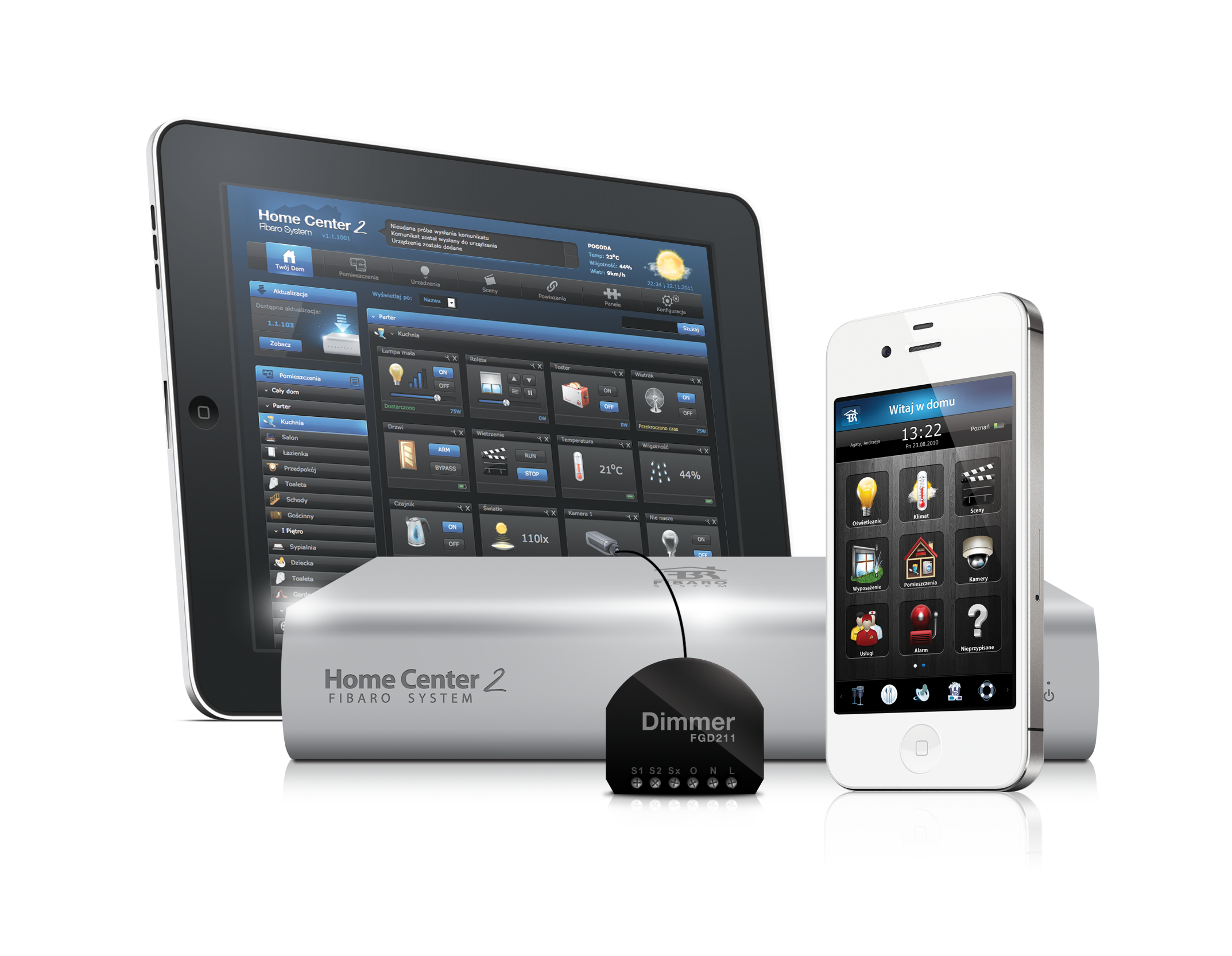
65 Chapter 5 Home Center 2 The Home Center 2 is an electronic device which manages the Fibaro System. The HC2 communicates with the system components (sensors, Fibaro modules) located in user s house using wireless radio communication. The Home Center 2 contains certified Z-Wave communication module allowing for support of up to 230 devices, integrated within a Mesh network. The Home Center 2 uses a simple, user friendly interface for the Fibaro system. The device enables it s user to manage and control the house using any mobile or stationery device, with internet access, from anywhere in the world. 5.1 HC2 Finder In a typical configuration, the Home Center 2 should be connected directly to a router. This way the DHCP server will set the HC2 a dedicated dynamic IP. For the greatest ease of use we have provided designated software, the Home Center Finder, so that the user can find his/her HC2 IP within the local network. Home 59

66 60 CHAPTER 5. HOME CENTER 2 Center Finder scans the local network and displays the IP and MAC addresses of all available HC2 units.

67 5.2. YOUR HOUSE Your House Your house tab is the Home Center 2 interface main window. It displays all devices available within a given Fibaro System, such as modules, sensors and virtual devices. Elements are divided into groups, depending on the device type and location in certain room. Figure 5.1: Your Home tab

68 62 CHAPTER 5. HOME CENTER Rooms The Rooms tab is designed for adding rooms and sections, i.e. single rooms, room groups, floors, or any user-defined locations. To add a section, first enter it s name and click Add. The new section will be created and it s name will be displayed on left-hand list. After a new section has been created, new room within the section may be created. To do so, the room name must be entered, the desired section chosen, and the Add button clicked. Figure 5.2: Adding Rooms / Sections Window
69 5.4. DEVICES Devices Z-Wave Devices Inclusion The Devices tab enables management of devices included in the Fibaro System. Devices are Fibaro modules, Fibaro system compatible sensors, IP cameras and virtual devices. To add a Z-Wave device click Add. Once the system sets itself into learning mode, Perform the tasks described in the manuals (see chapters 3 and 4). Figure 5.3: Adding Devices Window IP Camera Inclusion To add new IP camera, click Add. A new window will pop up, in which all camera configuration options will be available. After completing the camera configuration, click Save on the top of the screen. When including new IP camera, following options need to be configured: Camera name Room in which the camera will be presented in the interface Camera model - May be picked from the list Camera access - User s login and password IP Address of the camera

70 64 CHAPTER 5. HOME CENTER 2 Figure 5.4: Adding IP Camera window JPG path - JPG picture is used in remote access. All the necessary information should be available in the camera s user manual MJPG path - MJPG stream path is used in local access. If the camera can be rotated - paths for each movement direction (specified in camera s user manual) Creating Virtual Devices Virtual devices were designed to control complicated devices such as boilers, air conditioning units and home appliances (kitchen, audio and video appliances). These kinds of devices may be managed through multiple component communication protocol, and the use of RS232 and Ethernet ports. The Fibaro System makes it possible to create new device types and create designated communication protocols. Managing virtual devices is performed with TCP/IP protocols - Target IP and TCP communication ports must be defined. Next, the user defines a designated button, and defines the communication to be sent after the button is used. The system supports string communicates

71 5.4. DEVICES 65 Figure 5.5: Adding Virtual Device Window (text data type). For example, turn ON command line for Toshiba projector will be as follows: GET /cgi-bin/webrc.cgi?p_on=ok HTTP/1.10x0D0x0A0x0D0x0A Another option is to create value slider. *NOTE If the device confirm communication receipt please choose wait for device s response option Figure 5.6: Virtual Device Example Icon

72 66 CHAPTER 5. HOME CENTER Deleting Devices To delete device, simply click Delete. Device may be successfully deleted after the HC2 enters the learning mode (please refer to Chapters 3 and 4). Figure 5.7: Deleting Device Window 5.5 Scenes TheScenes tab lets the user program complicated functions between multiple devices included in the system. Scenes may be initiated by weather condition, a series of intuitive timers or various sensor/module state. A Scene is a group of commands sent to user defined group of devices, e.g. open the blinds 50%; and set the lights to 30% brightness. Scenes may be triggered by clicking the Run scene button. Scene may be also triggered by user defined actions, e.g. run the scene if the motion sensor is tripped or the room temperature exceeds 27 degrees. Another option is to define the scene triggering timers, e.g. run the scene each day at 8:30, and on Monday at 12:15. To open a new scene window click Add. The new scene must me named and assigned to certain room for easier configuration. After general parameters have been set, The Scene Advanced tab should be opened. This is the tab in which the scene actions are programmed.

73 5.5. SCENES 67 Figure 5.8: New Scene Creation Window Example Scenes

74 68 CHAPTER 5. HOME CENTER Linked Devices Linked Devices combine several devices into one device. Using this function will result in controlling the group of related devices as if they were one single device. The group will be presented in the HC2 interface as a single device. The Home Center 2 offers four different Linked Devices panels:
75 5.6. LINKED DEVICES 69 Heating Air Conditioning Humidity Video gate
76 70 CHAPTER 5. HOME CENTER Linked Devices - Heating Heating linked devices was designed to enable link between Relay Switch module and temperature sensor. This linked may be used in control of boilers, floor heating, jacuzzis, swimming pools etc. After creating the linked devices, managing and scheduling is done by the use of Heating Panel. Figure 5.9: Linked Devices Heating Window
77 5.6. LINKED DEVICES Linked Devices - Air Conditioning Air conditioning linked devices are based on the same principle as Heating Linked Devices. It is possible to add multiple switches turning several air conditioning devices ON / OFF, so that air conditioning in multiple rooms or sections may be operated as a single device. After air conditioning liked devices has been created, managing and scheduling is done by the use of the Air Conditioning panel. Figure 5.10: Linked Devices Air Conditioning Window
78 72 CHAPTER 5. HOME CENTER Linked Devices - Humidity Humidity linked devices uses the principle described in 5.6.1/2. After Humidity linked devices have been created, managing and scheduling of the new devices is done through the Humidity Panel. Figure 5.11: Linked Devices humidity window

79 5.6. LINKED DEVICES Video Gate The Video gate is a link between three devices - an IP camera, the module responsible for opening the gate and the module responsible for triggering the doorbell. After the link has been created, the video gate may be controlled via an iphone. To create the video gate, three devices must be added to the link: an IP camera overlooking the gate, a Relay Switch used to open the gate and a Relay Switch connected to the doorbell. Figure 5.12: Linked Devices Video-gate Window
80 74 CHAPTER 5. HOME CENTER Panels Panels simplify managing groups of related devices serving the same functionality, such as heating, air conditioning, or watering the garden. Using Panels, you can easily program the devices schedule for the entire week SMS Panel SMS Home Management is available in selected countries and allows you to stay in control of your home even when you don t have a viable internet connection. SMS Panel lets you define SMS communications sent by the system, define the list of telephone numbers allowed to manage the house and top-up the return messages account, used for the confirmation messages sent from sensors etc. Figure 5.13: SMS Panel window Example messages: HC lights.livingroom.on -turns on all the lights in livingroom. HC lights.livingroom.off - turns off all the lights in livingroom. HC lights.house.status - sends the message informing of the status of all devices named light in the house. If, for example in the living room any light is on, an excerpt from the return message will appear as follows: livingroom: on. If all of the lights in the room are off, excerpt
81 5.7. PANELS 75 from a return message will appear as follows: livingroom: off. To use the functionality, return messages pool must be bought.

82 76 CHAPTER 5. HOME CENTER Alarm Panel The Alarm Panel is designed to manage the alarm control unit, integrated into the Fibaro System. The alarm central unit is integrated with the use of two Relay Switch 2x1,5kW modules. In the Alarm Panel, the following devices need to be present: Controlling Module - arming / disarming alarm Status Module - informing about zone status (armed / disarmed) Alarming Module - indicating armed zone breach The defined alarm will be presented in the Your House menu. Figure 5.14: Alarm Panel Alarm Integration For integrating the alarm system into Fibaro System, two Relay Switch 2x1,5kw modules may be used.
83 5.7. PANELS 77 Connect Arming/Disarming input of the alarm control unit to O1 and O2 of the first Relay Switch 2x1,5kW Connect Status, i.e. Armed / Disarmed output of the alarm control unit to S1 and S2 inputs of the first Relay Switch 2x1,5kW connect alarming input of the alarm control unit (Breach / No Breach) to outputs O1 and O2 of the second Relay Switch 2x1,5kW

84 78 CHAPTER 5. HOME CENTER Heating Panel The Heating Panel allows you to schedule heating programs at predetermined times. After the heating zones have been created and rooms are added to it, all devices responsible for maintaining the desired temperature will work in accordance with schedule. Figure 5.15: Heating panel window

85 5.7. PANELS Heating Panel The Cooling Panel allows you to schedule cooling programs at predetermined times. After the cooling zones have been created and rooms are added to it, all devices responsible for maintaining the desired temperature will work in accordance with schedule. Figure 5.16: Air Conditioning panel window

86 80 CHAPTER 5. HOME CENTER Humidity Panel The Humidity Panel allows you to schedule cooling programs at predetermined times. After the cooling zones have been created and rooms are added to it, all devices responsible for maintaining the desired temperature will work in accordance with schedule. Figure 5.17: Humidity panel window History Panel The History Panel is a register of all of the activities taking place in a given Fibaro System. The panel lets the user monitor changes in status of all devices and filter them depending on the time they occured.
87 5.7. PANELS Access Control The Users Panel is configured to manage the accounts of the users of a certain HC2 unit. It allows you to grant/block access to the devices, e.g. cameras; scenes and system settings. From the Users Panel it is also possible to grant/block access using the hotel mode for a given mobile application, or set a perion for reporting GPS locations from a certain iphone device. Also, the Users Panel gives an option to define mobile devices which will receive Push Notifications. Figure 5.18: Access Control Panel After clicking the user s name, the Users Panel shows the window shown in fig Login Password (at least 4 characters. The system will ask for password confirmation) address (all notifications will be sent to this ) If the user is receive the notification massages

88 82 CHAPTER 5. HOME CENTER 2 Figure 5.19: User configuration window If the user is to be tracked - how frequently GPS position from the user s iphone will be collected. The shorter collection time, the more frequent readouts, resulting in more accurate positioning. Hotel mode - which rooms should be included in hotel mode for the user Hotel Mode Hotel mode is designed for defining a single room, that a given user will be able to manage through the iphone interface. For example, if there is USER 1 in the system, and the room ROOM 1 assigned to the user, the person will be able to manage this single room only through his iphone application. Users Rights Management. Users Panel gives the possibility for advanced control over users rights. It is possible to grant or block an access to: Devices - rights to operate certain devices Cameras - rights to check the image from certain IP cameras
89 5.7. PANELS 83 Scenes - rights to use certain scenes System - rights to manage certain system sections List of ios devices This enables you to determine which of the users using ios applications are to receive Push notifications. If the user is allowed to remotely access to the system, his iphone must be marked on the list.

90 84 CHAPTER 5. HOME CENTER Notifications Panel Notifications panel gives the ability to create messages to be used for informing the user of certain events taking place in the house. Figure 5.20: Notification Panel

91 5.7. PANELS Localization Panel Localization Panel uses user defined GPS points to activate GPS scenes. There are two ways of defining GPS points - choosing on a map, or entering certain GPS coordinates. Each user may enter indefinite number of GPS points. Figure 5.21: Localization Panel Usage example: USER 1 defines two GPS points HOME and WORK. Now it is possible to create scene turning OFF all the lights in the house once the user leaves the HOME location, and arms the alarm at home once the user enters WORK location.
92 86 CHAPTER 5. HOME CENTER Configuration The Home Center 2 configuration options are divided into the following categories: General LAN settings Location Backup General Basic information about the Home Center 2, including: Serial no. MAC address Current software version Z-Wave chip software version Time and date last software update was performed Time and date last system backup file was created Server status General information window also allows for performing following actions: Restart - Home Center 2 soft restart, i.e. system shut down and started again Z-Wave network reset - All of the system devices will be removed from HC2 Z-Wave chip memory, i.e. all of the device will have to be re-added to the system Default settings - Home Center 2 memory is reset to factory state, i.e. all of the devices are deleted together with their settings and dependencies (scenes). HC2 software is downgraded to it s oldest available version. After resetting to defaults, the HC2 software needs to be upgraded to latest available version.
93 5.8. CONFIGURATION 87 Figure 5.22: Configuration Panel - General LAN Settings There are two basic options available: DHCP or Static IP. Following parameters may be defined: Home Center 2 IP address Subnet mask Default gateway IP, used by HC2 to connect the web DNS server address Remote access enabling Figure 5.23: Configuration Panel - LAN settings
94 88 CHAPTER 5. HOME CENTER 2 Important information on LAN settings By default, the HC2 expects to be connected to a DHCP server. In this mode, HC2 IP address may be obtained with the use of the HC2 Finder (see HC2 Finder). Another option is to set Static IP. Static IP may be set from the LAN settings tab, or manually, by holding the Recovery button (back side of the HC2 casing) after the device has been connected to power supply. In this case, the HC2 will have following settings: IP Address: Subnet Mask: Gateway address: When static IP has been set, it is possible to connect HC2 directly to Ethernet port of a PC, however PC network settings must be set to match those of HC2: PC/MAC IP: Subnet mask:: Gateway address: NOTICE After setting a static IP for the HC2 by pressing and holding the Recovery button, please enter LAN settings to change connection type to DHCP, when the HC2 is connected to the PC.
. Figure 5.")
95 5.8. CONFIGURATION Location Location settings include time zone location, within which HC2 is installed. Additionally, it is possible to enter the longitude and latitude used for monitoring weather conditions (also used in scenes). Figure 5.24: Configuration Panel - Location info

96 90 CHAPTER 5. HOME CENTER Backup In this section the list of created backup files is displayed. Backup file is a copy of a file containing the information s about all devices added to the system and all of their settings, users individual settings and the HC2 operating system. Retrieving data from backup file means going back to all of the systems settings that had been saved. Figure 5.25: Configuration Panel - Backup Creation Window

97 5.9. RECOVERY MODE Recovery Mode Recovery Mode is a special panel, designed for retrieving the HC2 operating system in case of technical problems, e.g. when it is not possible to log into the user s panel. Using recovery mode the Home Center 2 will be brought back to the factory installed software version, i.e To access Recovery mode: 1. Turn the Home Center 2 OFF 2. When turning the Home Center 2 ON again, hold Recovery button in the back of HC2 casing - diodes will turn ON sequentially, starting from the left hand side 3. Entering Recovery Mode is signaled with a control diode NOTE! if you press and hold the recovery button for too long, the HC2 will set to static IP and network connection will be lost (see 5.8.2) Figure 5.26: Recovery Mode View The left hand menu displays the following information: Recovery version HC2 serial no IP Address - IP address, visible in local network MAC address - Module name and software version

98 92 CHAPTER 5. HOME CENTER 2 Figure 5.27: Recovery Mode - retrieving from backup Last backup - The date and time when last backup file was created Devices - The Number of devices saved in last backup file Rooms - The Number of rooms saved in last backup Scenes - The Number of scenes saved in last backup file Online - The HC2 internet access
Advanced User s Guide
 Advanced User s Guide ver. 1.06 Contents Contents I 1 Fibaro System - General Information 1 2 The Z-Wave Protocol 3 2.1 Device Types.............................. 3 2.2 How the network works........................
Fibaro electronic modules are smallest devices of the type in the World and can be installed in all standard wall switch boxes,
 Fibaro Z-Wave modules: Compatible with any Z-Wave home automation system, Fibaro electronic modules are smallest devices of the type in the World and can be installed in all standard wall switch boxes,
ZME_05459 Wall Blind Control Set for Busch-Jaeger DURO 2000 Firmware Version : 1.8
 ZME_05459 Wall Blind Control Set for Busch-Jaeger DURO 2000 Firmware Version : 1.8 Quick Start A This device is a Z-Wave Actuator. Triple click one of the buttons on the device will include the device.
ZME_RC2 Z-Wave Remote Control
 ZME_RC2 Z-Wave Remote Control Firmware Version : 1.1 Quick Start S This device is a Z-Wave Remote Control with the logical function of a sensor. Push the "Include" button behind the slider on the back
Z-Wave.Me Wall Controller
 Z-Wave.Me Wall Controller ZME_06443: Wall Controller Firmware Version 1.1 1 General Information about Z- Wave Safe: Generally radio systems build a direct link between the transmitter and the receiver.
TX GSM SMS Auto-dial Alarm System. Installation and User Manual
 TX GSM SMS Auto-dial Alarm System Installation and User Manual Product Features: 1. 16 wireless zones, 3 wired zones alarm system, suitable for small to medium size offices and homes. 2. The system uses
Business/Home GSM Alarm System. Installation and User Manual
 Business/Home GSM Alarm System Installation and User Manual Brief Introduction: GSM 900/1800/1900 bands, can be used in most parts of the world Full duplex communication with the host Monitor the scene
Adding to Z-Wave TM Network
 PAN04-1/-2/-3 In Wall Dual relay(1 way) switch module This in-wall switch module is able to detect Instant power wattage (5~1500W) and overload wattage (1600~1700W) of connected light or appliances. When
contents Leading the way in intelligent automation INELS Wireless? Why Click Accessories Complete control
 Wireless Control Systems Accessories Leading the way in intelligent automation contents Range Overview Typical Installations Transmitters Combined Modules Accessories Programming Switching & Dimmer Functions
EM6556 e-domotica Mini Switch
 EM6556 e-domotica Mini Switch EM6556 e-domotica Mini Switch 2 ENGLISH Table of contents 1.0 Introduction...2 1.1 Functions and features...2 1.2 Packing contents...2 2.0 Using the mini switch...3 2.1 Use
IP Box Camera ACM-5711. Ver. 081016. Hardware User s Manual
 IP Box Camera ACM-5711 Ver. 081016 Hardware User s Manual 0 0 PRECAUTIONS 1. Read these instructions All the safety and operating instructions should be read before the product is operated. 2. Heed all
Battery Wall Controller. Manual
 Battery Wall Controller Manual 009303 Battery Wall Controller Manual Quick Start... 2 Product Description... 3 Installation Guidelines... 3 Behavior within the Z-Wave Network... 4 Operating the Device...
Two-way communication, keep checking the commnunication between the panel and accessories, make sure the system safer.
 Innovative GSM & WIFI dual network operating platform. On WIFI network, the alarm system will work without any fee. If no WIFI, it will work on GSM automatically. With state-of-the-art WIFI network technology,
DOMUSBOX. User guide. Index
 DOMUSBOX User guide Index Introduction... 2 1. Installing SEAV DOMUS... 4 1.1 Activating DomusBox... 4 1.2Drawing the environments in DomusWeb... 5 1.3Connecting DomusBox to the devices...9 1.4Configuration
Please refer to the chapters below for detailed information about all aspects of the products usage.
 EUR_STELLAZ Wall Radiator Thermostat Valve Control Firmware Version : 0.4 Quick Start S This device is a wireless sensor. All operation is performed using the little button behind the round hole in the
Home Security and Control
 Bright House Networks Home Security and Control Product Description Table of Contents Introduction... 3 Understanding Basic Security Terms and Functionality... 4 Security Zones... 4 Arming Modes... 4 Arm
ST815 Illumination Sensor with LCD
 ST815 Illumination Sensor with LCD The Illumination Sensor with LCD (refer to as Illumination Sensor hereafter) is a Z-Wave TM enabled device which is fully compatible with any Z-Wave TM enabled network.
Users Manual of GSM Home Alarm System with Photo-taken
 GSM-IV REMOTE CAMERA MANNAL The Excellent GSM + Camera alarm system bases on the GSM network, integrates the communication technology, can automatic screen a photo with the intruder or burglar, and send
Solar Powered Outdoor Siren Manual
 005107 Solar Powered Outdoor Siren Manual 1 Solar Powered Outdoor Siren Manual Quick Start... 2 Product Description... 2 Installation Guidelines... 3 Behavior within the Z-Wave Network... 3 Operating the
Firmware version: 1.10 Issue: 7 AUTODIALER GD30.2. Instruction Manual
 Firmware version: 1.10 Issue: 7 AUTODIALER GD30.2 Instruction Manual Firmware version: 2.0.1 Issue: 0.6 Version of the GPRS transmitters configurator: 1.3.6.3 Date of issue: 07.03.2012 TABLE OF CONTENTS
Wireless AUTODIAL GSM SMS Home Alarm Security System 900/ 1800/ 1900Mhz(CK-GSM-9003)
") CN2HK LIMITED Wireless AUTODIAL GSM SMS Home Alarm Security System 900/ 1800/ 1900Mhz(CK-GSM-9003) User Manual Please read this manual before operating this product. After you finish reading this manual,
CN2HK LIMITED Wireless AUTODIAL GSM SMS Home Alarm Security System 900/ 1800/ 1900Mhz(CK-GSM-9003) User Manual Please read this manual before operating this product. After you finish reading this manual,
Quick start: Panic Watch EU
 Quick start: Panic Watch EU Technical specs Normal operating voltage Frequency range Wireless Range 1x CR2032 3V battery 868.42 MHz Min 150 meters in a mesh network Basic operations - The Panic Watch can
GSM ALARM SYSTEM USER MANUAL
 GSM ALARM SYSTEM USER MANUAL 1. Instruction The alarm system is based on GSM network. With a GSM SIM card, it can be used wherever you want and no need to connect any wire, which is convenient and easy
Business/Home. GSM Alarm system
 Business/Home GSM Alarm system Installation and Users guide Profile For a better understanding of this product, please read this user manual thoroughly before using it. I. General information: GSM 900/1800/1900
Basics of Dimming. ISC Learning Centre
 ISC Learning Centre July 2009 > Dimmers Contents What is a dimmer? Dimmers & customer benefits Dimmers at home Dimmers at the office Dimmers: technical choices Overview of the Schneider Electric offer
PROFESSIONAL HOME ALARM SYSTEM. Important! Please read these instructions carefully.
 WIRELESS AUTODIAL HOME ALARM SYSTEM AM2000 Instructions for use Important! Please read these instructions carefully. IMPORTANT 1 IDENTIFICATION PLEASE CONTACT BEFORE RETURNING THIS PRODUCT TO THE RETAILER
ZME_WALLC-S Z-Wave Secure Wall Controller
 ZME_WALLC-S Z-Wave Secure Wall Controller Firmware Version : 1.0 Quick Start S This device operates as Z-Wave sensor in two modes: the normal control mode (daily use) or in management mode for setup. Pushing
Wireless peripherals
 Wireless peripherals EYE-02 GSM Security Camera Application note File name: EYE-02 Wireless peripherals 1/12 1 INTRODUCTION The application note describes possibilities of using camera EYE-02 with wireless
MAKING MODERN LIVING POSSIBLE. living connect. Installation and User Guide. Danfoss heating
 MAKING MORN LIVING POSSIBLE Danfoss heating living connect Installation and User Guide Contents 1.0 System overview... 3 2.0 Overview of display and control buttons... 3 3.0 Installation - step by step...
SPL 2-00/-01 OPERATION INSTRUCTIONS
 SPL 2-00/-01 OPERATION INSTRUCTIONS Powerline Ethernet Adapter 500 Mbps EN Read and keep Operation Instructions SPL 2-00/-01 Safety Notes Do NOT use this product near water, for example, in a wet basement
Business/Home GSM. Alarm System(III) Installation and Users guide
 Installation and Users guide") Business/Home GSM Alarm System(III) Installation and Users guide I. General information: GSM 900/1800/1900 bands, can be used all over the world. Full duplex communication with the base. Monitor environment
Business/Home GSM Alarm System(III) Installation and Users guide I. General information: GSM 900/1800/1900 bands, can be used all over the world. Full duplex communication with the base. Monitor environment
PowerNodes. Energy Management
 PowerNodes Home Energy Management Table of Contents Introduction 2 PowerNode Overview 3 Installation 6 Common Z-Wave Tasks 10 Network Inclusion Process 10 Network Exclusion Process 11 Safety Information
MOBILE CALL GSM Alarm System User s Manual
 MOBILE CALL GSM Alarm System User s Manual Profile For a better understanding of this product, please read this user manual thoroughly before using it. Contents Function Introduction Alarm Host Diagram
Inwall 4 Input / 4 Output Module
 Inwall 4 Input / 4 Output Module IO44C02KNX Product Handbook Product: Inwall 4 Input / 4 Output Module Order Code: IO44C02KNX 1/27 INDEX 1. General Introduction... 3 2. Technical data... 3 2.1 Wiring Diagram...
Intelligent GSM Auto-Dial Alarm System
 Auto-dial Alarm System Intelligent GSM Auto-Dial Alarm System Profile For a better understanding of this product, please read this user manual thoroughly before using it. 2013.2.V1.0 Auto-dial Alarm System
BURGLAR ALARM SYSTEMS BURGLAR ALARM SYSTEMS BURGLAR ALARM SYSTEM EURO ALARM WIRELESS BURGLAR ALARM SYSTEM OASIS
 BURGLAR ALARM SYSTEMS BURGLAR ALARM SYSTEMS BURGLAR ALARM SYSTEM EURO ALARM WIRELESS BURGLAR ALARM SYSTEM OASIS BURGLAR ALARM SYSTEM EURO ALARM Six zones with the following connection capabilities: One
Six-defense zone Display Alarm System. User Manual
 Six-defense zone Display Alarm System User Manual Feature 1. Anti-interfere function. When someone interferes it with same frequency, the control unit will activate siren to alarm. 2. Support anti-decode
GSM Home Alarm System User Manual. http://www.usmartbuy.com
 GSM Home Alarm System User Manual http://www.usmartbuy.com 1 1. Factory default Normally, all sensors in the big box have been coded (learnt) to the control host Operation Password: 0000 Long-Distance
Welcome to a whole new level of interactive home security
 Welcome to a whole new level of interactive home security User Manual TouchScreen Key Fob Keychain Remote Web Access Mobile Access ReadyHome User Manual Introducing a whole new level of security for the
Alarm Security Kit - NVR
 Alarm Security Kit - NVR EN The alarm configuration menu (see above right screenshot) allows you to configure and change settings for the PIR movement sensors, window/door sensors, remote controls (key
Home Security Alarm System
 Home Security Alarm System User Manual (ALM-S02) Read manual carefully before use. PiSector Inc., USA www.pisector.com Thank you for purchasing this home security alarm system. For your safety and better
S100. GSM House Alarm System. Http://www.GSMalarmsystem.com
 S100 GSM House Alarm System Http://www.GSMalarmsystem.com 1. Brief introduction The GSM Alarm System is a new security protection solution special for home, house and office and other applications. It
DC-8706K Auto Dial Alarm System
 DC-8706K Auto Dial Alarm System User Guide Basic Contents: 1x the host unit; 1x wireless door (window) magnet; 1x wireless infrared detector; 2x remote control; 1x siren; 1x phone core; 1x AC to DC power
HomeSafe-Basic VT-PS99E. User s Manual. PSTN Home Alarm System. Page: 1 / 15
 HomeSafe-Basic VT-PS99E User s Manual PSTN Home Alarm System Page: 1 / 15 Table of Contents 1. Product Overview:... 3 2. Main Functions & Features... 3 3. For Your Safety... 4 4. VT-PS99E Characteristics...
How To Use A Power Supply On A Powerline 2.2 (Ai)
") KNX/EIB Product documentation Issue: 05.08.2010 629x1220 Push button sensor 3 comfort 1-gang Push button sensor 3 comfort 2-gang (1+1) Push button sensor 3 comfort 3-gang Push button sensor 3 comfort 4-gang
KNX/EIB Product documentation Issue: 05.08.2010 629x1220 Push button sensor 3 comfort 1-gang Push button sensor 3 comfort 2-gang (1+1) Push button sensor 3 comfort 3-gang Push button sensor 3 comfort 4-gang
Wireless Auto-dial Intruder Alarm System
 Wireless Auto-dial Intruder Alarm System User Manual User s Manual Profile For a better understanding of this product, please read this user manual thoroughly before using it. Features and Function 1.
15 Series - Electronic step relay and dimmer. Features 15.91 15.51 15.81 SERIE
 Series - Electronic step relay and dimmer SERIE Features.91.51.81 Electronic step relay and dimmer for control of lighting levels Suitable for incandescent and halogen lighting loads (with or without transformer
LW-2000-3A. Wireless Auto Dial Alarm System. Sentry Plus User Manual By Global Gadgets
 LW-2000-3A Wireless Auto Dial Alarm System Sentry Plus User Manual By Global Gadgets Main Features Simple to use keypad for operation and control. The system can store up to 9 telephone numbers: positions
Wireless Alarm system s manual
 MOUNTVIEW TECH AUSTRALIA PTY LTD Wireless Alarm system s manual ADS A180 Series ADS Security 1/11/2011 1. Before You Begin For your safety and the safety of others, and to ensure that you get the most
Additional Instruction
 Additional Instruction Note: a. Please connect the camera with 2.4G WIFI router or Ethernet cable, can t support 5G router. b. For first time wifi connection, please put your mobile close to camera within
SMART SENSOR COLLECTION
 TEMPERATURE SENSOR This sensor measures temperature in degrees Celsius or Fahrenheit. It works with all SensorHawk base units (SensorHawk-2, SensorHawk-8 and SensorHawk8/20) as well as the SecurityHawk-8
Quick Start Guide For Vera Advanced Home Security Solution
 Quick Start Guide For Vera Advanced Home Security Solution Congratulations on Your Purchase of the Vera Advanced Home Security Solution You ve taken the first step to begin enjoying the ease, convenience
NVMS-1200. User Manual
 NVMS-1200 User Manual Contents 1 Software Introduction... 1 1.1 Summary... 1 1.2 Install and Uninstall... 1 1.2.1 Install the Software... 1 2 Login Software... 3 2.1 Login... 3 2.2 Control Panel Instruction...
GSM Gate Opener GSM Remote Switch RTU5015 User Manual
 GSM Gate, Barrier, Shutter, Garage Door and Door opener Open gate or garage door with a FREE call from your mobile phone! Remote switching machines with a FREE call from your mobile phone! GSM Gate Opener
How To Control A Car Alarm On A Car With A Remote Control System
 MODEL CA100 REMOTE CONTROL AUTO ALARM SYSTEM INSTALLATION & OPERATION INSTRUCTIONS WIRING DIAGRAM Black Antenna Wire 6 Pin 6 Pin Mini Connector Valet Switch Blue LED Indicator Blue Wire: (-) 200mA Unlock
Quick start: Energy Switch EU
 Technical specifications Normal operating voltage Quick start: Energy Switch EU 230Vac/50Hz Recommended max. load 3000W 600W Frequency range Wireless range Energy measurement 868.42 MHz 30~100 meters in
LYNX Touch Series Security Systems
 LYNX Touch Series Security Systems Home Automation Guide 800-11309 3/12 Rev. A Z-Wave Programming The LYNX Touch control features Z-Wave technology that is designed to automate devices in a home control
Security. Alarm central unit. Ref.-No. KNX Alarm central unit EAM 4000
 Security Alarm Central Unit 3 4 Technical KNX Alarm central unit EAM 4000 ETS-product family: Alarm system Product type: Alarm central unit The alarm central unit is a modern alarm system using the KNX
PSTN Home Alarm System
 PSTN Home Alarm System User Manual Model: PST-TEL99E Please read this user guide carefully before operation and installation. Contents 1. Product Overview... - 3-2. Main Function & Features... - 3-3. For
Quick Start Guide For Vera Small Business Solution
 Quick Start Guide For Vera Small Business Solution Congratulations on Your Purchase of the Vera Small Business Solution You ve taken the first step to begin enjoying the ease, convenience, energy savings
ImagineWorldClient Client Management Software. User s Manual. (Revision-2)
") ImagineWorldClient Client Management Software User s Manual (Revision-2) (888) 379-2666 US Toll Free (905) 336-9665 Phone (905) 336-9662 Fax www.videotransmitters.com 1 Contents 1. CMS SOFTWARE FEATURES...4
ImagineWorldClient Client Management Software User s Manual (Revision-2) (888) 379-2666 US Toll Free (905) 336-9665 Phone (905) 336-9662 Fax www.videotransmitters.com 1 Contents 1. CMS SOFTWARE FEATURES...4
mysensors mysensors Wireless Sensors and Ethernet Gateway Quick Start Guide Information to Users Inside the Box mysensors Ethernet Gateway Quick Start
 mysensors Information to Users mysensors Wireless Sensors and Ethernet Gateway Quick Start Guide This equipment has been tested and found to comply with the limits for a Class B digital devices, pursuant
SNMP Web card. User s Manual. Management Software for Uninterruptible Power Supply Systems
 SNMP Web card User s Manual Management Software for Uninterruptible Power Supply Systems Table of Contents 1. Overview... 3 1.1 Introduction... 3 1.2 Features... 3 1.3 Overlook... 3 1.4 Installation and
Overview. Components of an alarm system Technology behind the equipment Communication Platforms Industry Terminology False Alarm Tips DSC products
 Basic Security 101 Overview Components of an alarm system Technology behind the equipment Communication Platforms Industry Terminology False Alarm Tips DSC products Components of an Alarm System Main Control
KNX Gateway RGK02-5023E-01
 KNX Gateway RGK02-5023E-01 Table of contents Page 1 General Information 1.1 Technical data 5 1.2. Intended Use 6 1.3 Specifications 6 1.4 Compatibility 6 1.5 Scope of delivery 6 2 Information about the
Drayton Digistat +2RF/+3RF
 /+3RF Programmable Room Thermostat Wireless Model: RF700/22090 Model: RF701/22092 Power Supply: Battery - Thermostat Mains - Digistat SCR Invensys Controls Europe Customer Service Tel: 0845 130 5522 Customer
ibaby Monitor Model: M3s User Manual
 ibaby Monitor Model: M3s User Manual Index 1 Introduction...3 1.1 The package contents...3 1.2 Product Features...3 1.3 Product Specifications...4 2 Appearance and Interface...5 2.1 Appearance...5 2.2
Getting started with
 PART NO. CMA113 MADE IN CHINA 1. Measuring CAT II 2. Max. voltage 250V ~ 3. Max. current 71 Amp Getting started with Electricity consumption monitoring single phase for homes and some smaller light commercial
Temperature & Humidity SMS Alert Controller
 Temperature & Humidity Alert Controller METERS 3 simple steps starting the unit: Insert the SIM card Plug in the sensors connectors Connect the AC power cord. Specifications: AC 90~260V Auto Select Internal
ALARM SYSTEM INSTALLATION GUIDE
 ALARM SYSTEM INSTALLATION GUIDE Congratulations on the purchase of your Egardia alarm system. Egardia's website www.egardia.com Customer services Please visit www.egardia.com if you would like further
Table of Contents. 1. Introduction...1. 2. PDU Package...2. 3. Function...3. 4. Installation...5. 5. Web Interface...7
 PDU User Manual Table of Contents 1. Introduction...1 2. PDU Package...2 3. Function...3 4. Installation...5 5. Web Interface...7 1. Introduction The PDU is an Internet ready device designed and is equipped
CHAPTER 2: USING THE CAMERA WITH THE APP
 TABLE OF CONTENTS OVERVIEW... 1 Front of your camera... 1 Back of your camera... 2 ACCESSORIES... 3 CHAPTER 1: Navigating the Mobile Application... 4 Device List: How to Use this Page... 4 My Messages:
PCS300 Universal IP Reporting Module V1.0
 PCS300 Universal IP Reporting Module V1.0 Reference and Installation Manual Patents: One or more of the following US patents may apply: 7046142, 6215399, 6111256, 6104319, 5920259, 5886632, 5721542, 5287111,
Automation System TROVIS 6400 TROVIS 6493 Compact Controller
 Automation System TROVIS 6400 TROVIS 6493 Compact Controller For panel mounting (front frame 48 x 96 mm/1.89 x 3.78 inch) Application Digital controller to automate industrial and process plants for general
Home Monitoring and Control service provided by Verizon Online LLC
 Home Monitoring and Control service provided by Verizon Online LLC A separate subscription to Verizon FiOS TV is required for use with FiOS TV service. About This Manual This manual is designed for online
Mureva Assembly surface mounted wiring devices
 1.0 Waterproof Assembly surface Switches P124543 P124547 External dimensions : 72 x 72 x 47 mm.. Assembly surface rockers become illuminated using bulbs and indicators in option. They can carry a label
Ademco Vista-20P/First Alert FA-168C Basic Commands
 Zones 64 total Ademco Vista-20P/First Alert FA-168C Basic Commands Wireless Yes, Zones 09 to 48 + 16 Keyfob Zones (Zones 49 to 64) Batteries Downloadable Partitions 2 12 volt Rechargable inside main Panel,
TYXIA. *2702178_Rev.1* Installation and User Guide. Wireless receiver. TYXIA RF 642-1 channel
 Installation and User Guide TYXIA Wireless receiver TYXIA RF 642-1 channel DELTA DORE Bonnemain - 35270 COMBOURG - France E-mail : deltadore@deltadore.com Unit compliant with the requirements of directives:
Intruder Alarm System
 Intruder Alarm System GSM & PSTN Wireless and Wired Touch Model 2013-01 V1.0.0 Statment This equipment must be installed and used in strict accordance with the instructions given in this user documentation.
Product and functional description
 Product and functional description The KNX / DALI gateway N 141/02 is a 4 MU wide, DINrail mounted KNX device with one DALI interface to which up to 64 DALI actuators (e.g. DALI ballasts) can be connected
USER MANUAL. PingBrother EPIW104 managed passive poe switch & IP watchdog
 USER MANUAL PingBrother EPIW104 managed passive poe switch & IP watchdog CONTENT Content... 2 Chapter 1... 3 1.1 Preface... 3 1.2 CE mark warning... 3 1.3 FCC warning... 4 Chapter 2... 5 2.1 Physical description...
GSM home alarm system s manual
 GSM home alarm system s manual I. Main features: 1, Eight wireless LED zone, and four wired zone 2, Two-way to communication 3, The system supports the GSM cell phones, no need the fixed telephone line.
VTO6xxx. IP door stations. User manual
 VTO6xxx IP door stations User manual Table of Contents 1 Product Appearance 2 Basic Function Introduction 2.1 Call Manager Center 2.2 Call User 2.2.1 Connecting Status 2.2.2 Calling Status 2.3 Monitor
ViewPower. User s Manual. Management Software for Uninterruptible Power Supply Systems
 ViewPower User s Manual Management Software for Uninterruptible Power Supply Systems Table of Contents 1. ViewPower Overview... 2 1.1. Introduction...2 1.2. Structure...2 1.3. Applications...2 1.4. Features...2
User's Guide. [Home Network] app. Model No.
![User's Guide. [Home Network] app. Model No.](/thumbs/26/8329814.jpg "User's Guide. [Home Network] app. Model No.") User's Guide [Home Network] app Model No. Table of Contents Table of Contents 1 Welcome to the Panasonic Home Network System!...5 1.1 What is the Panasonic Home Network System?...5 1.2 What can I use it
User's Guide [Home Network] app Model No. Table of Contents Table of Contents 1 Welcome to the Panasonic Home Network System!...5 1.1 What is the Panasonic Home Network System?...5 1.2 What can I use it
Ethernet Radio Configuration Guide
 Ethernet Radio Configuration Guide for Gateway, Endpoint, and Repeater Radio Units April 20, 2015 Customer Service 1-866-294-5847 Baseline Inc. www.baselinesystems.com Phone 208-323-1634 FAX 208-323-1834
SECTION 13850 DETECTION AND ALARM
 SECTION 13850 DETECTION AND ALARM PART 1 GENERAL 1.01 SUMMARY A. Section Includes 1. Control Panel 2 Associated Equipment B. Products Installed But Not Supplied Under This Section 1. Section 16140 - Wiring
Introduction to Z-Wave. An Introductory Guide to Z-Wave Technology
 Introduction to Z-Wave An Introductory Guide to Z-Wave Technology Table of Contents Z-Wave Overview and Functionality... 3 Z-Wave Technology Quick Overview... 3 Radio Specifications... 3 Network and Topology...
500r+ Installation and User Guide
 500r+ Installation and User Guide Compatible Equipment 502rUK-50 Watch/Pendant PA. 509rUK-50 Smoke Detector 515rUK-00 10 metre passive infra red movement detector. 525rUK-00 Remote Set/Unset (Full and
GSM Gate Opener GSM Remote Switch RTU5015. User Manual. Ver 1.3 Date Issued: 2010-08-18. All rights reserved by King Pigeon Hi-Tech. Co., Ltd.
 GSM Gate, Barrier, Shutter, Garage Door and Door opener Open gate or garage door with a FREE call from your mobile phone! Remote switching machines with a FREE call from your mobile phone! GSM Gate Opener
LCD -based Intelligent Burglar Alarm System. User Guide. Ver 2.0
 LCD -based Intelligent Burglar Alarm System User Guide Ver 2.0 Table of Content 1. Introduction... 2 1.1 General Description... 3 1.2 System Features... 3 2. Anatomy of the LCD-based Intelligence Burglar
Danfoss Link Mobile Phone Butler
 MAKIG MODER LIVIG POSSIBLE Installation Guide www.heating.danfoss.com Table of Contents 1 Introduction... 3 2 Installation... 3 3 Interfaces... 4 4 Wiring... 4 5 SMS Commands... 5 6 Technical Specifications...
Remote Client Program... 3. Web Client... 39
 Remote Client / Web Client USER MANUAL T Series Digital Video Recorder Remote Client Program... 3 Remote Client Program Installation... 4 Remote Client... 6 Main Window... 6 Site Registration... 7 Group
Transmitter Actuator 230V wave UP 560. Operation
 Transmitter ctuator 230V wave UP 560 5WG3 560-201 Product- and pplication Description Diagram The transmitter actuator 230V wave UP 560 (Diagram ) is a flush-mounted device with radio communication for
B.IQ push button 3-5gang with room thermostat and display V2, flush-mounted 7566359x, 7566459x, 7566559x
 B.IQ push button 3-5gang with room Product name: Design: ETS search path: B.IQ push button 3-, 4-, 5gang with room thermostat and display V2 Flush-mounted Push button / B.IQ / B.IQ push button xgang with
DALI DIM/CONVERTER CONTROL (DC NV) 1 10V (0-10 V) analog DALI Converter with (Multi-) Sensor-control and 1 and 2-Switch dim functions
 1 10V (0-10 V) analog DALI Converter with (Multi-) Sensor-control and 1 and 2-Switch dim functions") DAI DIM/COVERTER COTRO (DC V) 1 10V (0-10 V) analog DAI Converter with (Multi-) Sensor-control and 1 and 2-Switch dim functions Dim-and Switch Functions: The DAI Dim/Converter Control DC V is suitable
DAI DIM/COVERTER COTRO (DC V) 1 10V (0-10 V) analog DAI Converter with (Multi-) Sensor-control and 1 and 2-Switch dim functions Dim-and Switch Functions: The DAI Dim/Converter Control DC V is suitable
Version:G300 V2.0 11.04. Business/Home GSM Alarm System. Installation and Users' Guide. ( 99 wireless zones)
") Version:G300 V2.0 11.04 Business/Home GSM Alarm System Installation and Users' Guide ( 99 wireless zones) Brief Introduction: GSM 850/900/1800/1900 bands, can be used in most parts of the world Full duplex
Version:G300 V2.0 11.04 Business/Home GSM Alarm System Installation and Users' Guide ( 99 wireless zones) Brief Introduction: GSM 850/900/1800/1900 bands, can be used in most parts of the world Full duplex
PhoneWatch Smart Security System User Manual - Domonial
 PW0002 10/13 Customer Support: 1850 753 753 PhoneWatch Ltd., Unit 3/4, Sandyford Park, Burton Hall Rd, Sandyford Industrial Estate, Dublin 18. Email: info@phonewatch.ie PhoneWatch Smart Security System
INSTALLATION MANUAL VEHICLE SECURITY SYSTEM CE-SS200
 INSTALLATION MANUAL VEHICLE SECURITY SYSTEM CE-SS200 FUSION CULTURE TABLE OF CONTENTS There s no point doing something if no one notices. We ve always believed the way to make things happen is by getting
INSTRUCTION MANUAL All-In-One GSM Home Alarm System SB-SP7200-GSM
 INSTRUCTION MANUAL All-In-One GSM Home Alarm System SB-SP7200-GSM Revised: August 28, 2014 PRODUCT REFERENCE MOUNTING ACCESSORIES PIR / MOTION DETECTION UNIT MAIN UNIT POWER ADAPTER MOUNTING ACCESSORIES