MTS ADHESIVES PROGRAMME PERFORMANCE OF ADHESIVE JOINTS
|
|
|
- Augusta Hunt
- 7 years ago
- Views:
Transcription
1 MTS ADHESIVES PROGRAMME PERFORMANCE OF ADHESIVE JOINTS Project: PAJ1; Failure Criteria and their Application to Visco-Elastic/Visco-Plastic Materials Report 6 MEASUREMENT OF CREEP AND STRESS RELAXATION IN RUBBER AND RUBBER TYPE MATERIALS F HU A OLUSANYA This report represents deliverables in Task2 and Task 5, Milestones M5 and M19 December 1997

2 Crown copyright 1997 Reproduced by permission of the Controller of HMSO ISSN National Physical Laboratory Teddington, Middlesex, UK, TW11 0LW No extracts from this report may be reproduced without the prior written consent of the Managing Director National Physical Laboratory; the source must be acknowledged. Approved on behalf of Managing Director, NPL, by Dr C Lea, Head of Centre of Materials Measurement & Technology 2

3 CONTENTS 1. Introduction 4 2. Creep And Stress Relaxation In Rubber Materials 4 3. Test Methods Creep Tests Stress Relaxation Tests Creep Rupture Tests Compressive Creep Tests 7 4.Presentation Of Creep Data 7 5.The Creep Power Law 8 6. Concluding Remarks 9 7.References 10 8.List Of Figures 10 3

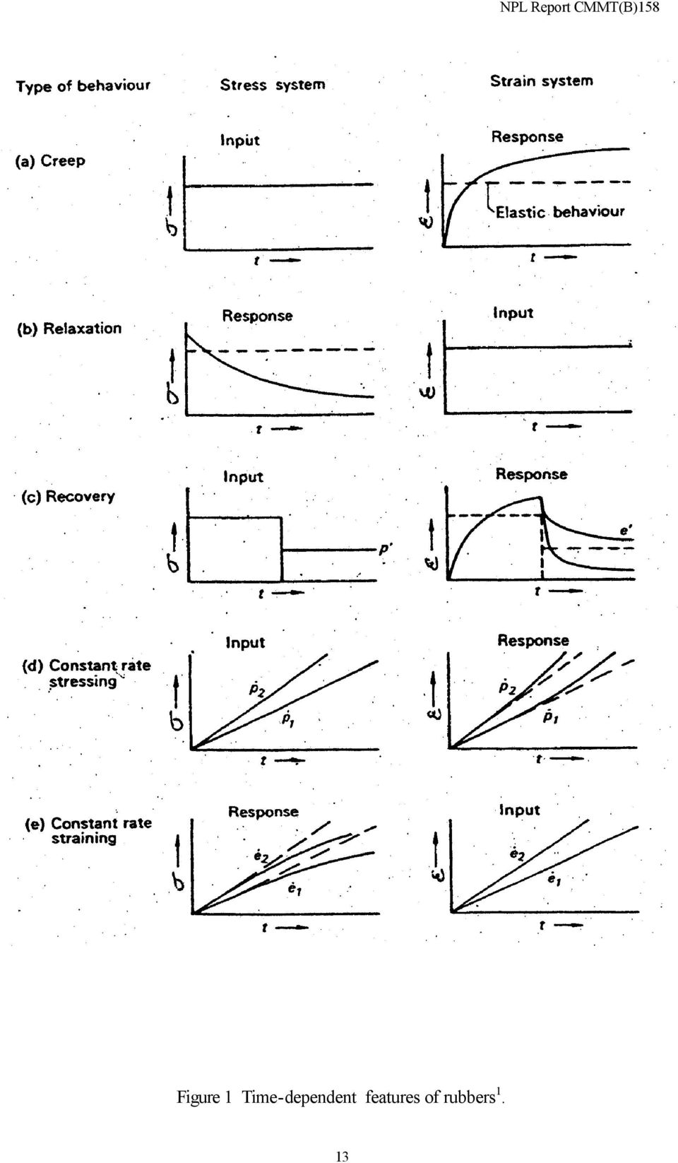
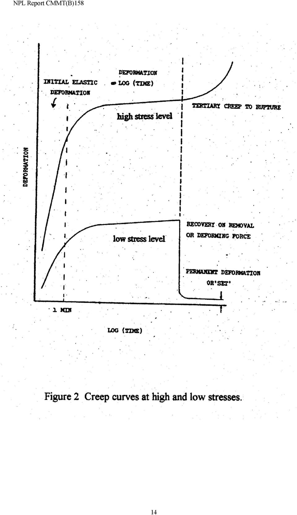
4 MEASUREMENT OF CREEP AND STRESS RELAXATION IN RUBBER AND RUBBER TYPE MATERIALS 1. Introduction Failure criteria under creep and stress relaxation are important in many applications and especially for rubber and rubber-like components. In structural joints that employ flexible adhesives, creep or stress relaxation of the adhesive will result in stress redistribution in the bond line leading to deformation that increases with service time. The creep and stress relaxation properties of adhesives are essential data requirements for design engineers so that the adhesively bonded components can be designed and utilised effectively and safely. The objective of this report is to review test methods for the measurement of creep and stress relaxation of rubber materials. 2. Creep and Stress Relaxation in Rubber Materials The concepts of creep and stress relaxation and other related time dependent responses of rubbers are depicted in Figure 1 for a simple tension stress system of stress, σ and strain, ε. The behaviour of linear elastic materials is also shown in Figure 1 (dashed lines) for comparison. Creep is defined as the continuing time dependent deformation under constant stress, while stress relaxation is defined as the time dependent decay in stress that results from the application of a constant deformation. Unlike metallic materials that only show creep and stress relaxation under relatively large stresses or at high temperature, all rubbers exhibit these characteristics whenever they are subjected to force or deformation. In general for structural uses these characteristics are undesirable, however these properties can be used to advantage in compression loading for, seals and flanges and vibration damping components for automotive, aerospace and assorted diverse engineering applications The typical creep performance of a rubber under high and low stresses is illustrated in Figure 2. A linear relationship is often obtained when the deformation is plotted against the logarithm of time. However, under a very high stress and extended time periods, the linear relationship may be succeeded by an upward curve leading to creep rupture. The initial elastic deformation due to the applied load and a typical recovery curve obtained when the applied load is removed are also shown in Figure Test Methods 3.1 Creep tests Creep tests can be carried out by applying a constant load to the test specimen, and measuring its deformation as a function of time. Creep tests may involve stressing specimens in almost any mode, tension, compression, flexure, shear, etc., depending on the proposed use of the material. 4

5 It may be necessary to devise tests to apply combinations of the above stress modes, however, the uniaxial tension creep test is the most widely used because it is simple and easy to carry out. If the material is isotropic and displays a linear creep response, its behaviour under complex stresses can be fully characterised by the time dependent tensile creep modulus and the time dependent creep lateral contraction ratio, Poisson s ratio. The stress can be applied by hanging weights on the specimen and the elongation can be determined by an extensometer, periodically measuring the distance between two fiducial marks on the specimen. If there is no slippage in the grips holding the specimen, the device for measuring the elongation may be attached to the specimen grips and changes in length may be determined from the separation of the grips. ASTM 2990 gives general guidance for the creep testing of rubbers. It is found that the specimen alignment is critical and the load eccentricity should be within 1% of the axis of specimen loading. The sensitivity of the extensometer for the measurement of change in length should be in/in or better. The tests are all performed at a constant temperature. The main standards relating to measurement of creep of plastics and rubbers are listed in Table 1. Physical testing of rubber, BS903 covers visco-elastic properties in the following sections: Part A5: Determination of tension set; Part A6: Determination of compression set after constant strain; Part A15: Measurement for determination of creep in compression or shear; Part A34: Determination of stress relaxation of rubber rings in compression; Part A42: Determination of stress relaxation. Figure 3 shows the uniaxial creep test arrangements using single-lever or two-lever loading systems. The stresses are generally achieved by the application of simple dead loads. Creep tests have been conducted at NPL for the study of the behaviour of metallic and polymeric materials. The existing facilities include three types of measurement instrument: i) constant-load single-lever machines without strain measurement, ii) constant-stress cam-lever machines with strain measurement, iii) constant strain rate screw-driven machines with strain measurement operated under constant load. Temperature and humidity are also controlled. The measurements in this project will be performed using constant-load single-lever machines without strain measurement. Operational procedures for carrying out uniaxial creep testing are listed in Table 2. 5

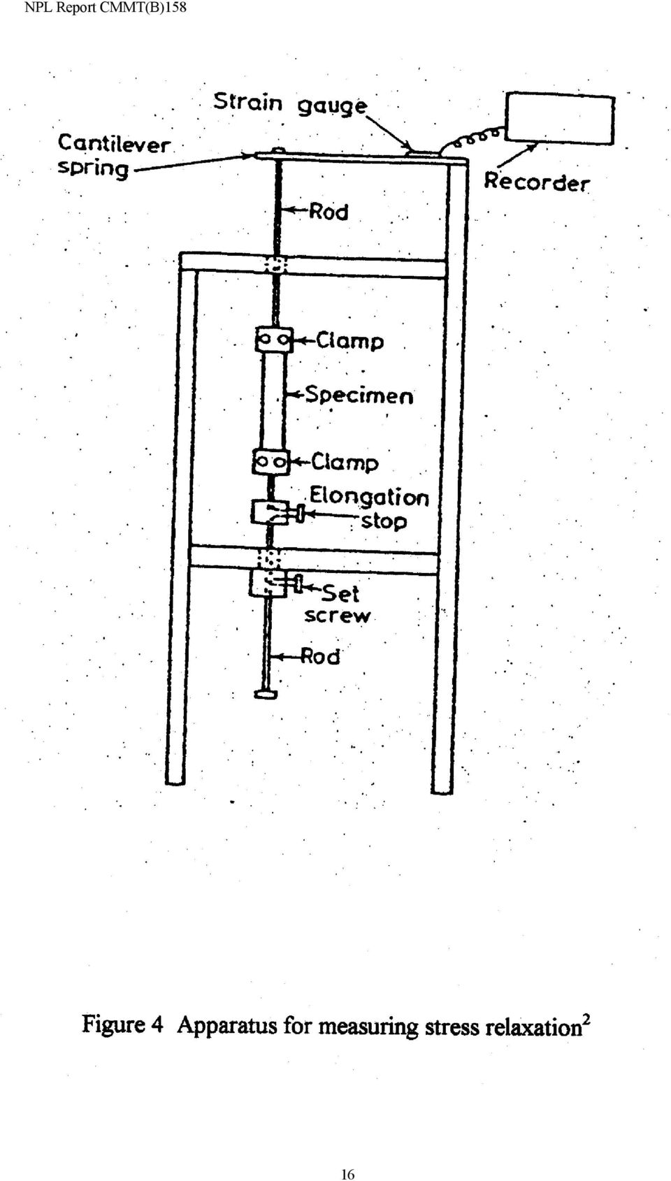
6 3.2 Stress relaxation tests In a stress-relaxation test, the specimen is deformed a fixed amount, and the stress required to maintain this deformation is measured for the requisite period of time. The maximum stress occurs when the deformation takes place, and the stress decreases gradually with time from this maximum value. Many types of instruments have been used to measure stress relaxation. Relatively simple instruments can be used for rubber materials. The apparatus must be rigid compared to the specimens and the transducer used to measure the stress must be capable of operating with very little deformation. Figure 4 shows an apparatus for measuring stress relaxation. The stress is measured by a strain gauge attached to a cantilever beam spring. When a stress is applied to the specimen, the beam is displaced a slight amount. This displacement is transmitted to the strain gauge, changing its resistance and the electrical output; the electrical input is fed into the recorder to give a trace proportional to stress (or force) versus time. The elongation is applied to the specimen by quickly pulling down on the lower rod. The elongation stop allows one to impose any fixed elongation to the specimen. The elongation is held constant by tightening the lower set screw. 3.3 Creep rupture tests A creep rupture test measures the time to break under constant stresses. Specimens are under high stresses, usually expressed as a fraction of the ultimate, short term failure strength. Creep rupture test data are usually presented by as a creep-rupture envelope, a graphical representation of applied stress against the logarithm of rupture time. These envelopes indicate the limits of a material s load-bearing capability. For adhesive joints, the creep rupture data of adhesive materials is possibly the most important time-dependent property as a short-term safe joint could potentially fail as the service time increases. Therefore, the degradation of joint strength against the service time should be determined by using the creep rupture data of adhesives. A creep rupture curve requires a minimum of seven stress levels and rupture should occur at approximately the following times: 1, 10, 30, 100, 300, 1000 and 3000 hours. The selection of temperatures for creep rupture testing depends on the work condition of the material. Measurements should be carried out at a minimum of two test temperatures. Examples of this type of test are rarely seen in practice as rubber components such as seals are generally operating at stress levels far below their working limits. Similar stress rupture tests are described in ASTM2992, UK Oil and Offshore Association standards, UKOOA, describing tests relevant to plastic pipes under internal pressure. 6

7 3.4 Compressive creep tests Compressive creep tests can be used to determine the creep modulus and the creep lateral contraction, Poisson s ratio for rubber materials. A uniaxial compression test is performed by loading a sample of material between lubricated surfaces. The loading surfaces are lubricated to prevent the sticking of the test sample to the loading faces and also to minimise the barrelling effect that lead to deviations from homogeneous compression stress-strain situation. Satisfactory lubrication of the end faces is difficult to achieve and in any event the resultant stress-strain curve is dependent on the shape of the test sample, in particular the ratio of the axial to the lateral dimension. Thus data from the stress strain curve requires modification to model different shapes of the same material. It is found that the superposition of a tensile or compressive stress on a loaded incompressible body realises different stresses but does not result in a change of deformation. Thus apparently different loading conditions are actually equivalent in their deformation and are therefore equivalent test. As a result, a uniaxial compression test can be realised by a equibiaxial tension test. It is found under superposition of stresses that these tests are equivalent; Uniaxial tension Equibiaxial compression Uniaxial compression Equibiaxial tension Planar tension Planar compression. It is also found that uniaxial tension and uniaxial compression are independent from each other, as is the case for equibiaxial tension and equibiaxial compression. 4. Presentation of Creep Data The primary data of creep tests are normally displayed as creep curves, Figure 5. This shows the total deformation (or strain) against logarithmic time at different stress levels. For uniaxial tension creep tests, the stress levels can be selected from the following range, 0.01σ ult, 0.02σ ult, 0.05σ ult, 0.1σ ult, 0.2σ ult, 0.3σ ult, 0.5σ ult, 0.7σ ult, 0.8σ ult and 0.9σ ult, where σ ult is the short-term ultimate failure strength of the material. Each group of these curves is measured from the specimens cut from the same batch and tested at the same temperature and moisture conditions. The result of stress relaxation tests can be presented as shown in Figure 6. The measured stress is plotted against logarithmic time for each specimen tested under a different constant strain. A stress-log time curve can also be obtained by interpolating the data from creep curves if the data represents a wide range of stress levels. For a specific strain level (dotted line in Figure 5), 5 to 8 pairs of stress - log time values can generate a curve in Figure 6, this is not the same curve though, for a particular strain. 7

8 Creep rupture tests will generate a curve as shown in Figure 7, in which time to failure is recorded for each constant stress applied. The stress levels can be selected as 0.95σ ult, (σ ult is the short-term ultimate strength), 0.90σ ult, 0.85σ ult, 0.80σ ult, 0.75σ ult, to 0.30σ ult. Under higher stresses, the creep rate is higher and the material fails in a shorter time. Tests are normally started from high stress level. A test is usually terminated in 2000 to 3000 hours if it does not fail under a lower stress level. The highest stress at which specimens do not break is called creep limit strength. From a set of creep curves at various stresses, Figure 5, it is possible to construct isochronous stress-strain curves, Figure 8, by drawing lines at fixed time period, for example 0, 1, 10, 100 hours. Creep curves can also be presented in a 3-dimensional stress-straintime co-ordinate system. 5. The Creep Power Law This section describes an experimental procedure which enables the determination of the material constants that appear in the creep power law. The terminology of the finite element modelling software program ABAQUS 5 will be used. As:. cr n k ε = Aq t (1.1). cr where ε is the equivalent creep strain rate, q is the von Mises equivalent stress, t is time and A, n and k are material constants to be determined. Integrating equation (1) leads to: = A k + 1 q t (1.2) ε cr n k+1 where ε cr form: is the equivalent creep strain. Equation (1.2) can be converted to a logarithmic log ( ε cr ) = A log ( ) ( ) where B=A/(k+1). + nlogq + k + 1 logt = logb + nlogq + k +1 logt (1.3) k +1 Equation (1.3) can be used in conjunction with uniaxial creep experimental data to determine the material constants, A, n and k. 8

9 The experimental procedure is as follows: i) A uniaxial creep test is carried out where the applied load is constant. The creep strain as a function of time is measured, i.e. q, the von Mises equivalent stress, is constant and the time t is varied. For a uniaxial tensile test, ε cr,the equivalent creep strain rate, is equal to the creep strain and q is equal to the applied stress. A plot of logε cr vs. logt is produced. The gradient of the regression line that fits the experimental data, will be equal to (k+1), hence k can be evaluated. The intercept of the line will be equal to (logb+nlogq). ii) A number of creep tests with various constant loads are carried out and the resulting creep strain after a constant time period, i.e. keep t constant and vary q is measured. A plot of log ε cr vs. logq, will have a gradient equal to n. The intercept will be equal to {logb+(k+1)logt)}. As k is now known, B and hence A can now be ascertained. A cross check on accuracy can be carried out by calculating B via the intercept obtained in procedure i. Note that in all of the above, it is assumed that a constant applied load gives rise to a constant stress, q, therefore, the above procedure is valid only if the reduction in the specimen s cross section during creep, is negligible. 6. Concluding Remarks Adhesives can be considered as isotropic materials, thus for linear behaviour only the creep modulus and creep lateral contraction ratio, Poisson s ratio, are required to characterise their creep behaviour under multi-axial stresses. These two creep parameters can be measured just by an uniaxial tension creep test. Compressive creep testing can also be used to measure these two parameters, for linear behaviour, but this method of testing is not feasible for rubbers. It is necessary to conduct creep rupture tests to measure the creep strength in fixed amount of time. Creep rupture envelopes at different temperatures can be generated by creep rupture tests under specified stress levels. 9
 A number of creep tests with various constant loads are carried out and the resulting creep strain after a constant time period, i.e. keep t constant and vary q is measured. A plot of log ε cr vs.")
10 7.References 1. J. G. Williams, Stress analysis of polymers, Longman Group Ltd., G. C. Ives, J. A. Mead and M. M. Riley, Handbook of plastics test methods, ILIFFE Books, P. K. Freakley and A. R. Payne, Theory and practice of engineering with rubber, Applied Science Publishers, S. Osgerby and M. S. Loveday, Creep laboratory manual, NPL Report DMM(A)37, June ABAQUS User s and Theory Manuals, Version 5.5, Hibbit, Karlsson & Sorensen Inc., USA, List Of Figures Figure 1 Time-dependent features of rubbers Figure 2 Creep curves at high and low stresses Figure 3 Typical loading systems for tensile creep tests Figure 3(a) Single lever loading system Figure 3(b) Two lever creep machine Figure 4 Apparatus for measuring stress relaxation Figure 5 Creep curves: Strain Vs time at various constant stresses. Figure 6 Stress relaxation curves: Stress Vs time at various constant strains. Figure 7 Creep rupture curve: Stress Vs time to failure. Figure 8 Stress - strain curves at different loading times. 10
 Single lever loading")
11 Table 1:Standards relating to measurement of creep and stress relaxation in rubber and polymeric materials BS903: Part A15: 1990: Physical testing of rubber: Method for determination of creep in compression or shear. (Identical to ISO 8013). BS903: Part A34: 1978: Physical testing of rubber: Determination of stress relaxation of rubber rings in compression. BS903: Part A42: 1992: Physical testing of rubber: Method for determination of stress relaxation in compression at ambient and at elevated temperature. (Identical to ISO 3384). BS903: Part A52: 1986(1995): Physical testing of rubber: Determination of ageing characteristics by measurement of stress at a given elongation. (Identical to ISO 6914). BS4618: 1970 (1994): Recommendations for the presentation of plastics design data; Part 1: Mechanical properties; Section 1.1 Creep: Creep in uniaxial tension or compression (with particular reference to solid plastics) Creep in flexure at low strains Creep lateral contraction ratio (Poisson s ratio) BS5350: Methods of test for adhesives; Part C7: 1990: Determination of creep and resistance to sustained application force. ISO 899-1: 1993: Plastics - Determination of creep behaviour - Part 1: Tensile creep. ISO 899-2: 1993: Plastics - Determination of creep behaviour - Part 1: Flexural creep by three-point loading. ASTM D , Test method for rubber - viscosity, stress relaxation and prevulcanisation characteristics (Mooney viscometer). ASTM D , Practice for conducting creep tests of metal-to-metal adhesives. ASTM D , Standard test method for tensile, compressive, and flexural creep and creep rupture of plastics. ASTM D , Standard test method for creep properties of adhesives in shear by compression loading (metal-to-metal). ASTM D , Standard test method for creep properties of adhesives in shear by tension loading (metal-to-metal). 11
: Physical testing of rubber: Determination of ageing characteristics by measurement of stress at a given elongation. (Identical to ISO 6914).")
12 ASTM D , Standard test method for strength properties of adhesives in shear by tension loading at elevated temperatures (metal-to-metal). ASTM D2992(1977), Standard Method for Obtaining Hydrostatic Design Basis for Reinforced Thermosetting Resin Pipes and Fittings. UKOOA GRP Work Group, Specifications and Recommended Practice for the Use of Piping Offshore, Table 2:Operational procedures for NPL creep laboratory. Code Intro TSP1 TSP2 TSP3 TSP4 TSP5 TSP6 TSP7 CSP1 CSP2 CSP3 CSP4 CSP5 CSP6 CSP7 CSP8 Title Creep laboratory manual: Introduction Initiation of test and progress chasing Material identification and registry Measurement of specimens Creep test method Specimen manufacture Repair and maintenance of equipment Laboratory environment and service Machine load calibration Load cell calibration Thermocouple calibration Transducer calibration Extensometer calibration Calibration of specimen measurement apparatus Calibration of weights Verification of laser extensometer calibrator 12

13 Figure 1 Time-dependent features of rubbers 1. 13
14 14
15 15 NPL Report CMMT(B)158

16 16
17 Strain Stress 5 Stress 4 Stress 3 Stress 2 Stress 1 Log time Figure 5 Creep curves: Strain Vs time at various constant stresses. Stress Strain 5 Strain 1 Log time Figure 6 Stress relaxation curves: Stress Vs time at various constant strains. Stress Log time Figure 7 Creep rupture curve: Stress Vs time to failure. 17

18 Stress Increasing time t 1 t 2 t 3 Strain Figure 8 Stress - strain curves at different loading times. 18

Objectives. Experimentally determine the yield strength, tensile strength, and modules of elasticity and ductility of given materials.
 Lab 3 Tension Test Objectives Concepts Background Experimental Procedure Report Requirements Discussion Objectives Experimentally determine the yield strength, tensile strength, and modules of elasticity
Long term performance of polymers
 1.0 Introduction Long term performance of polymers Polymer materials exhibit time dependent behavior. The stress and strain induced when a load is applied are a function of time. In the most general form
Stress Strain Relationships
 Stress Strain Relationships Tensile Testing One basic ingredient in the study of the mechanics of deformable bodies is the resistive properties of materials. These properties relate the stresses to the
Tensile Testing Laboratory
 Tensile Testing Laboratory By Stephan Favilla 0723668 ME 354 AC Date of Lab Report Submission: February 11 th 2010 Date of Lab Exercise: January 28 th 2010 1 Executive Summary Tensile tests are fundamental
Hardened Concrete. Lecture No. 14
 Hardened Concrete Lecture No. 14 Strength of Concrete Strength of concrete is commonly considered its most valuable property, although in many practical cases, other characteristics, such as durability
Chapter Outline. Mechanical Properties of Metals How do metals respond to external loads?
 Mechanical Properties of Metals How do metals respond to external loads? Stress and Strain Tension Compression Shear Torsion Elastic deformation Plastic Deformation Yield Strength Tensile Strength Ductility
Measurement of Residual Stress in Plastics
 Measurement of Residual Stress in Plastics An evaluation has been made of the effectiveness of the chemical probe and hole drilling techniques to measure the residual stresses present in thermoplastic
SHORE A DUROMETER AND ENGINEERING PROPERTIES
 SHORE A DUROMETER AND ENGINEERING PROPERTIES Written by D.L. Hertz, Jr. and A.C. Farinella Presented at the Fall Technical Meeting of The New York Rubber Group Thursday, September 4, 1998 by D.L. Hertz,
METU DEPARTMENT OF METALLURGICAL AND MATERIALS ENGINEERING
 METU DEPARTMENT OF METALLURGICAL AND MATERIALS ENGINEERING Met E 206 MATERIALS LABORATORY EXPERIMENT 1 Prof. Dr. Rıza GÜRBÜZ Res. Assist. Gül ÇEVİK (Room: B-306) INTRODUCTION TENSION TEST Mechanical testing
Mechanical Properties of Metals Mechanical Properties refers to the behavior of material when external forces are applied
 Mechanical Properties of Metals Mechanical Properties refers to the behavior of material when external forces are applied Stress and strain fracture or engineering point of view: allows to predict the
3. Test Methods for Evaluation of ESCR of Plastics
 3. Test Methods for Evaluation of ESCR of Plastics A common laboratory request for ESC-prone polymers is to check ESCR performance for quality control, competitive product evaluations, and research and
ASTM D 1599 Standard Test Method for Resistance to Short-Time Hydraulic Pressure of Plastic Pipe, Tubing, and Fittings
 ASTM D 1599 Standard Test Method for Resistance to Short-Time Hydraulic Pressure of Plastic Pipe, Tubing, and Fittings This test method establishes the short-time hydraulic failure pressure of pipe and
15. MODULUS OF ELASTICITY
 Chapter 5 Modulus of Elasticity 5. MODULUS OF ELASTICITY The modulus of elasticity (= Young s modulus) E is a material property, that describes its stiffness and is therefore one of the most important
Nonlinear Analysis Using Femap with NX Nastran
 Nonlinear Analysis Using Femap with NX Nastran Chip Fricke, Principal Applications Engineer, Agenda Nonlinear Analysis Using Femap with NX Nastran Who am I? Overview of Nonlinear Analysis Comparison of
Numerical Analysis of Independent Wire Strand Core (IWSC) Wire Rope
 Wire Rope") Numerical Analysis of Independent Wire Strand Core (IWSC) Wire Rope Rakesh Sidharthan 1 Gnanavel B K 2 Assistant professor Mechanical, Department Professor, Mechanical Department, Gojan engineering college,
Numerical Analysis of Independent Wire Strand Core (IWSC) Wire Rope Rakesh Sidharthan 1 Gnanavel B K 2 Assistant professor Mechanical, Department Professor, Mechanical Department, Gojan engineering college,
Overview of Topics. Stress-Strain Behavior in Concrete. Elastic Behavior. Non-Linear Inelastic Behavior. Stress Distribution.
 Stress-Strain Behavior in Concrete Overview of Topics EARLY AGE CONCRETE Plastic shrinkage shrinkage strain associated with early moisture loss Thermal shrinkage shrinkage strain associated with cooling
Torsion Tests. Subjects of interest
 Chapter 10 Torsion Tests Subjects of interest Introduction/Objectives Mechanical properties in torsion Torsional stresses for large plastic strains Type of torsion failures Torsion test vs.tension test
Lecture 12: Fundamental Concepts in Structural Plasticity
 Lecture 12: Fundamental Concepts in Structural Plasticity Plastic properties of the material were already introduced briefly earlier in the present notes. The critical slenderness ratio of column is controlled
Introduction to Solid Modeling Using SolidWorks 2012 SolidWorks Simulation Tutorial Page 1
 Introduction to Solid Modeling Using SolidWorks 2012 SolidWorks Simulation Tutorial Page 1 In this tutorial, we will use the SolidWorks Simulation finite element analysis (FEA) program to analyze the response
EDEXCEL NATIONAL CERTIFICATE/DIPLOMA MECHANICAL PRINCIPLES OUTCOME 2 ENGINEERING COMPONENTS TUTORIAL 1 STRUCTURAL MEMBERS
 ENGINEERING COMPONENTS EDEXCEL NATIONAL CERTIFICATE/DIPLOMA MECHANICAL PRINCIPLES OUTCOME ENGINEERING COMPONENTS TUTORIAL 1 STRUCTURAL MEMBERS Structural members: struts and ties; direct stress and strain,
DETERMINATION OF TIME-TEMPERATURE SHIFT FACTOR FOR LONG-TERM LIFE PREDICTION OF POLYMER COMPOSITES
 DETERMINATION OF TIME-TEMPERATURE SHIFT FACTOR FOR LONG-TERM LIFE PREDICTION OF POLYMER COMPOSITES K. Fukushima*, H. Cai**, M. Nakada*** and Y. Miyano*** * Graduate School, Kanazawa Institute of Technology
Technology of EHIS (stamping) applied to the automotive parts production
 applied to the automotive parts production") Laboratory of Applied Mathematics and Mechanics Technology of EHIS (stamping) applied to the automotive parts production Churilova Maria, Saint-Petersburg State Polytechnical University Department of Applied
Laboratory of Applied Mathematics and Mechanics Technology of EHIS (stamping) applied to the automotive parts production Churilova Maria, Saint-Petersburg State Polytechnical University Department of Applied
Validation of Cable Bolt Support Design in Weak Rock Using SMART Instruments and Phase 2
 Validation of Cable Bolt Support Design in Weak Rock Using SMART Instruments and Phase 2 W.F. Bawden, Chair Lassonde Mineral Engineering Program, U. of Toronto, Canada J.D. Tod, Senior Engineer, Mine Design
Procon Engineering. Technical Document PELR 1002. TERMS and DEFINITIONS
 Procon Engineering Technical Document PELR 1002 TERMS and DEFINITIONS The following terms are widely used in the weighing industry. Informal comment on terms is in italics and is not part of the formal
A NEW APPROACH FOR MEASUREMENT OF TENSILE STRENGTH OF CONCRETE
 Journal of Research (Science), Bahauddin Zakariya University, Multan, Pakistan. Vol.16, No.1, June 2005, pp. 01-09 ISSN 1021-1012 A NEW APPROACH FOR MEASUREMENT OF TENSILE STRENGTH OF CONCRETE A. Ghaffar,
CH 6: Fatigue Failure Resulting from Variable Loading
 CH 6: Fatigue Failure Resulting from Variable Loading Some machine elements are subjected to static loads and for such elements static failure theories are used to predict failure (yielding or fracture).
PENETRATION OF BITUMINOUS MATERIALS
 NANYANG TECHNOLOGICAL UNIVERSITY School of Civil and Structural Engineering LABORATORY - PAVEMENT MATERIALS PENETRATION OF BITUMINOUS MATERIALS OBJECTIVES To examine the consistency of a sample of bitumen
1. Fluids Mechanics and Fluid Properties. 1.1 Objectives of this section. 1.2 Fluids
 1. Fluids Mechanics and Fluid Properties What is fluid mechanics? As its name suggests it is the branch of applied mechanics concerned with the statics and dynamics of fluids - both liquids and gases.
THE COMPOSITE DISC - A NEW JOINT FOR HIGH POWER DRIVESHAFTS
 THE COMPOSITE DISC - A NEW JOINT FOR HIGH POWER DRIVESHAFTS Dr Andrew Pollard Principal Engineer GKN Technology UK INTRODUCTION There is a wide choice of flexible couplings for power transmission applications,
Ultrasonic Reference Blocks
 Ultrasonic Reference Blocks Custom and Standard Test Blocks for Nondestructive Testing Introduction 3 IIW Type 1 Calibration Block 4 Miniature Angle Beam (ROMPAS) Calibration Block 4 Distance Calibration
EDEXCEL NATIONAL CERTIFICATE/DIPLOMA MECHANICAL PRINCIPLES AND APPLICATIONS NQF LEVEL 3 OUTCOME 1 - LOADING SYSTEMS TUTORIAL 3 LOADED COMPONENTS
 EDEXCEL NATIONAL CERTIICATE/DIPLOMA MECHANICAL PRINCIPLES AND APPLICATIONS NQ LEVEL 3 OUTCOME 1 - LOADING SYSTEMS TUTORIAL 3 LOADED COMPONENTS 1. Be able to determine the effects of loading in static engineering
Lap Fillet Weld Calculations and FEA Techniques
 Lap Fillet Weld Calculations and FEA Techniques By: MS.ME Ahmad A. Abbas Sr. Analysis Engineer Ahmad.Abbas@AdvancedCAE.com www.advancedcae.com Sunday, July 11, 2010 Advanced CAE All contents Copyright
MECHANICAL CHARACTERIZATION
 Assay Centre Report No: SAM2818I Version: English Page: 1 of 14 Print date: 18/10/05 Final Report SAM2818I MECHANICAL CHARACTERIZATION Study Program No: SAM2818 Contract: E05/0137.4MI Sponsor: ANDROMEDICAL
The University of Birmingham (Live System)
") The University of Birmingham (Live System) Behaviour of Structural Insulated Panels (SIPs) under both short-term and long-term loadings Yang, Jian; Rungthonkit, Prathan Document Version Author final version
The University of Birmingham (Live System) Behaviour of Structural Insulated Panels (SIPs) under both short-term and long-term loadings Yang, Jian; Rungthonkit, Prathan Document Version Author final version
Uniaxial Tension and Compression Testing of Materials. Nikita Khlystov Daniel Lizardo Keisuke Matsushita Jennie Zheng
 Uniaxial Tension and Compression Testing of Materials Nikita Khlystov Daniel Lizardo Keisuke Matsushita Jennie Zheng 3.032 Lab Report September 25, 2013 I. Introduction Understanding material mechanics
The elements used in commercial codes can be classified in two basic categories:
 CHAPTER 3 Truss Element 3.1 Introduction The single most important concept in understanding FEA, is the basic understanding of various finite elements that we employ in an analysis. Elements are used for
ANALYSIS OF GASKETED FLANGES WITH ORDINARY ELEMENTS USING APDL CONTROL
 ANALYSIS OF GASKETED FLANGES WITH ORDINARY ELEMENTS USING AP... Page 1 of 19 ANALYSIS OF GASKETED FLANGES WITH ORDINARY ELEMENTS USING APDL CONTROL Yasumasa Shoji, Satoshi Nagata, Toyo Engineering Corporation,
Stress Relaxation Study of Paper and Plastic Film based Packaging Material
 Master's Degree Thesis ISRN: BTH-AMT-EX--2009/D-02--SE Stress Relaxation Study of Paper and Plastic Film based Packaging Material Rajdip Roy Lu Qi Department of Mechanical Engineering Blekinge Institute
MATERIALS AND MECHANICS OF BENDING
 HAPTER Reinforced oncrete Design Fifth Edition MATERIALS AND MEHANIS OF BENDING A. J. lark School of Engineering Department of ivil and Environmental Engineering Part I oncrete Design and Analysis b FALL
PROPERTIES OF MATERIALS
 1 PROPERTIES OF MATERIALS 1.1 PROPERTIES OF MATERIALS Different materials possess different properties in varying degree and therefore behave in different ways under given conditions. These properties
Solution for Homework #1
 Solution for Homework #1 Chapter 2: Multiple Choice Questions (2.5, 2.6, 2.8, 2.11) 2.5 Which of the following bond types are classified as primary bonds (more than one)? (a) covalent bonding, (b) hydrogen
ANALYTICAL AND EXPERIMENTAL EVALUATION OF SPRING BACK EFFECTS IN A TYPICAL COLD ROLLED SHEET
 International Journal of Mechanical Engineering and Technology (IJMET) Volume 7, Issue 1, Jan-Feb 2016, pp. 119-130, Article ID: IJMET_07_01_013 Available online at http://www.iaeme.com/ijmet/issues.asp?jtype=ijmet&vtype=7&itype=1
Naue GmbH&Co.KG. Quality Control and. Quality Assurance. Manual. For Geomembranes
 Naue GmbH&Co.KG Quality Control and Quality Assurance Manual For Geomembranes July 2004 V.O TABLE OF CONTENTS 1. Introduction 2. Quality Assurance and Control 2.1 General 2.2 Quality management acc. to
COMPUTATIONAL ENGINEERING OF FINITE ELEMENT MODELLING FOR AUTOMOTIVE APPLICATION USING ABAQUS
 International Journal of Advanced Research in Engineering and Technology (IJARET) Volume 7, Issue 2, March-April 2016, pp. 30 52, Article ID: IJARET_07_02_004 Available online at http://www.iaeme.com/ijaret/issues.asp?jtype=ijaret&vtype=7&itype=2
Drained and Undrained Conditions. Undrained and Drained Shear Strength
 Drained and Undrained Conditions Undrained and Drained Shear Strength Lecture No. October, 00 Drained condition occurs when there is no change in pore water pressure due to external loading. In a drained
2. The mold is closed up and held under hydraulic pressure while the rubber material or compound cures.
 Designing with Rubber Molding Processes Compression Molding Compression molding is the process of placing a pre-load of a rubber material or compound directly in the mold cavity and compressed to the shape
Structural Integrity Analysis
 Structural Integrity Analysis 1. STRESS CONCENTRATION Igor Kokcharov 1.1 STRESSES AND CONCENTRATORS 1.1.1 Stress An applied external force F causes inner forces in the carrying structure. Inner forces
Force measurement. Forces VECTORIAL ISSUES ACTION ET RÉACTION ISOSTATISM
 Force measurement Forces VECTORIAL ISSUES In classical mechanics, a force is defined as "an action capable of modifying the quantity of movement of a material point". Therefore, a force has the attributes
Material property tests of Smooth-on Vytaflex60 liquid rubber
 Material property tests of Smooth-on Vytaflex60 liquid rubber Sanjay R. Arwade March 16, 2006 During the fall semester of the 2005-2006 academic year, I decided to try to produce some scale models of structural
MECHANICAL PRINCIPLES HNC/D PRELIMINARY LEVEL TUTORIAL 1 BASIC STUDIES OF STRESS AND STRAIN
 MECHANICAL PRINCIPLES HNC/D PRELIMINARY LEVEL TUTORIAL 1 BASIC STUDIES O STRESS AND STRAIN This tutorial is essential for anyone studying the group of tutorials on beams. Essential pre-requisite knowledge
CASE HISTORY #2. APPLICATION: Piping Movement Survey using Permalign Laser Measurement System
 CASE HISTORY #2 APPLICATION: Piping Movement Survey using Permalign Laser Measurement System EQUIPMENT: Dresser-Clark Hot Gas Expander (Turbine), 60-inch Inlet Flange HISTORY: Piping support modifications
ENGINEERING COUNCIL CERTIFICATE LEVEL
 ENGINEERING COUNCIL CERTIICATE LEVEL ENGINEERING SCIENCE C103 TUTORIAL - BASIC STUDIES O STRESS AND STRAIN You should judge your progress by completing the self assessment exercises. These may be sent
Experimental study on the creep behaviour of GFRP pultruded beams
 Experimental study on the creep behaviour of GFRP pultruded beams Simone LONI 1, Ioannis STEFANOU 2, Paolo S. VALVO 1 1 Department of Civil and Industrial Engineering, University of Pisa - Italy E-mail:
AN EXPLANATION OF JOINT DIAGRAMS
 AN EXPLANATION OF JOINT DIAGRAMS When bolted joints are subjected to external tensile loads, what forces and elastic deformation really exist? The majority of engineers in both the fastener manufacturing
A COMPARATIVE STUDY OF TWO METHODOLOGIES FOR NON LINEAR FINITE ELEMENT ANALYSIS OF KNIFE EDGE GATE VALVE SLEEVE
 International Journal of Mechanical Engineering and Technology (IJMET) Volume 6, Issue 12, Dec 2015, pp. 81-90, Article ID: IJMET_06_12_009 Available online at http://www.iaeme.com/ijmet/issues.asp?jtype=ijmet&vtype=6&itype=12
σ y ( ε f, σ f ) ( ε f
 ( ε f") Typical stress-strain curves for mild steel and aluminum alloy from tensile tests L L( 1 + ε) A = --- A u u 0 1 E l mild steel fracture u ( ε f, f ) ( ε f, f ) ε 0 ε 0.2 = 0.002 aluminum alloy fracture
Typical stress-strain curves for mild steel and aluminum alloy from tensile tests L L( 1 + ε) A = --- A u u 0 1 E l mild steel fracture u ( ε f, f ) ( ε f, f ) ε 0 ε 0.2 = 0.002 aluminum alloy fracture
Report on the Use of Numerical Analysis for Strength Evaluation of Orthopedic Implants
 Provisional Translation (as of July 1, 2016) March 25, 2016 Report on the Use of Numerical Analysis for Strength Evaluation of Orthopedic Implants Yoichiro Matsumoto, Chairperson Takashi Yamane, Vice-chairperson
8.2 Elastic Strain Energy
 Section 8. 8. Elastic Strain Energy The strain energy stored in an elastic material upon deformation is calculated below for a number of different geometries and loading conditions. These expressions for
Thermal cover:layout 1 1/18/11 3:56 PM Page 2 TA Instruments
 TA Instruments Thermomechanical Analysis Sensitive Measurement, Unmatched Versatility TMA Q400EM/Q400 SPECIFICATIONS 98 The Q400EM is the industry s leading research-grade thermomechanical analyzer with
Composite Design Fundamentals. David Richardson
 Composite Design Fundamentals David Richardson Contents A review of the fundamental characteristics of composites Stiffness and Strength Anisotropic Role of fibre, matrix and interface Composite failure
Environmental Stress Crack Resistance of Polyethylene Pipe Materials
 Environmental Stress Crack Resistance of Polyethylene Pipe Materials ROBERT B. TAMPA, Product Development and Service Engineer* Abstract Slow crack growth is a phenomenon that can occur in most plastics.
22.302 Experiment 5. Strain Gage Measurements
 22.302 Experiment 5 Strain Gage Measurements Introduction The design of components for many engineering systems is based on the application of theoretical models. The accuracy of these models can be verified
Objective To conduct Charpy V-notch impact test and determine the ductile-brittle transition temperature of steels.
 IMPACT TESTING Objective To conduct Charpy V-notch impact test and determine the ductile-brittle transition temperature of steels. Equipment Coolants Standard Charpy V-Notched Test specimens Impact tester
NPL Manual. Manual for the Calculation of Elastic-Plastic Materials Models Parameters
 NL Manual Manual for the Calculation of Elastic-lastic Materials Models arameters his Electronic Guide was produced as part of the Measurements for Materials System rogramme on Design for Fatigue and Creep
A Study of Durability Analysis Methodology for Engine Valve Considering Head Thermal Deformation and Dynamic Behavior
 A Study of Durability Analysis Methodology for Engine Valve Considering Head Thermal Deformation and Dynamic Behavior Kum-Chul, Oh 1, Sang-Woo Cha 1 and Ji-Ho Kim 1 1 R&D Center, Hyundai Motor Company
STRENGTH of MATERIALS. P.A.Hilton Ltd. Two Year Warranty UNIVERSAL MATERIAL TESTER HARDNESS TESTERS DEFLECTION/FATIGUE IMPACT TESTERS POLARISCOPE
 P.A.Hilton Ltd STRENGTH of MATERIALS P.A.Hilton Ltd is a market leader in the manufacture and provision of teaching equipment for Universities and Technical Colleges worldwide for both degree and vocational
Description of mechanical properties
 ArcelorMittal Europe Flat Products Description of mechanical properties Introduction Mechanical properties are governed by the basic concepts of elasticity, plasticity and toughness. Elasticity is the
Numerical modelling of shear connection between concrete slab and sheeting deck
 7th fib International PhD Symposium in Civil Engineering 2008 September 10-13, Universität Stuttgart, Germany Numerical modelling of shear connection between concrete slab and sheeting deck Noémi Seres
TSL Professional Services
 Report For: Laboratory #: 402876-05 5375 Edgeway Drive, ALLENDALE, MI, USA Report Date: December 21, 2005 49401 Received Date: November 3, 2005 Phone: 616 875 7725 Fax: 616 875 6009 Customer P.O. #: COD
International Journal of Engineering Research-Online A Peer Reviewed International Journal Articles available online http://www.ijoer.
 RESEARCH ARTICLE ISSN: 2321-7758 DESIGN AND DEVELOPMENT OF A DYNAMOMETER FOR MEASURING THRUST AND TORQUE IN DRILLING APPLICATION SREEJITH C 1,MANU RAJ K R 2 1 PG Scholar, M.Tech Machine Design, Nehru College
PC-Concrete Injectable Concrete Anchoring and Repair System
 PC-Concrete Injectable Concrete Anchoring and Repair System DESCRIPTION: PC-Concrete is a two component (1:1 ratio), 100% solids, high modulus, structural epoxy paste. PC-Concrete is a solvent free, no
GRI Standard Practice GT7 * Determination of the Long-Term Design Strength of Geotextiles
 Geosynthetic Institute 475 Kedron Avenue Folsom, PA 19033-1208 USA TEL (610) 522-8440 FAX (610) 522-8441 GEI GRI GSI GAI GCI GII adopted -1989 Rev. 1 1992 Rev. 2 (editorial) 2012 GRI Standard Practice
Fatigue Performance Evaluation of Forged Steel versus Ductile Cast Iron Crankshaft: A Comparative Study (EXECUTIVE SUMMARY)
") Fatigue Performance Evaluation of Forged Steel versus Ductile Cast Iron Crankshaft: A Comparative Study (EXECUTIVE SUMMARY) Ali Fatemi, Jonathan Williams and Farzin Montazersadgh Professor and Graduate
Fatigue Performance Evaluation of Forged Steel versus Ductile Cast Iron Crankshaft: A Comparative Study (EXECUTIVE SUMMARY) Ali Fatemi, Jonathan Williams and Farzin Montazersadgh Professor and Graduate
STRAIN-LIFE (e -N) APPROACH
 APPROACH") CYCLIC DEFORMATION & STRAIN-LIFE (e -N) APPROACH MONOTONIC TENSION TEST AND STRESS-STRAIN BEHAVIOR STRAIN-CONTROLLED TEST METHODS CYCLIC DEFORMATION AND STRESS-STRAIN BEHAVIOR STRAIN-BASED APPROACH TO
CYCLIC DEFORMATION & STRAIN-LIFE (e -N) APPROACH MONOTONIC TENSION TEST AND STRESS-STRAIN BEHAVIOR STRAIN-CONTROLLED TEST METHODS CYCLIC DEFORMATION AND STRESS-STRAIN BEHAVIOR STRAIN-BASED APPROACH TO
Precision Miniature Load Cell. Models 8431, 8432 with Overload Protection
 w Technical Product Information Precision Miniature Load Cell with Overload Protection 1. Introduction The load cells in the model 8431 and 8432 series are primarily designed for the measurement of force
The Pipe/Soil Structure Actions and Interactions
 Chapter 4 The Pipe/Soil Structure Actions and Interactions Lester H. Gabriel, Ph.D., P.E. THE PIPE/SOIL STRUCTURE ACTIONS AND INTERACTIONS Composite Structures Principles of Analysis Predictability of
Use of Strain Gauge Rosette to Investigate Stress concentration in Isotropic and Orthotropic Plate with Circular Hole
 Use of Strain Gauge Rosette to Investigate Stress concentration in Isotropic and Orthotropic Plate with Circular Hole Mr.V.G.Aradhye 1, Prof.S.S.Kulkarni 2 1 PG Scholar, Mechanical department, SKN Sinhgad
Physics 3 Summer 1989 Lab 7 - Elasticity
 Physics 3 Summer 1989 Lab 7 - Elasticity Theory All materials deform to some extent when subjected to a stress (a force per unit area). Elastic materials have internal forces which restore the size and
TENSILE TESTING PRACTICAL
 TENSILE TESTING PRACTICAL MTK 2B- Science Of Materials Ts epo Mputsoe 215024596 Summary Material have different properties all varying form mechanical to chemical properties. Taking special interest in
THE STRAIN GAGE PRESSURE TRANSDUCER
 THE STRAIN GAGE PRESSURE TRANSDUCER Pressure transducers use a variety of sensing devices to provide an electrical output proportional to applied pressure. The sensing device employed in the transducers
METHOD OF STATEMENT FOR STATIC LOADING TEST
 Compression Test, METHOD OF STATEMENT FOR STATIC LOADING TEST Tension Test and Lateral Test According to the American Standards ASTM D1143 07, ASTM D3689 07, ASTM D3966 07 and Euro Codes EC7 Table of Contents
T 549. WORKING GROUP CHAIRMAN N/A; reaffirmed SUBJECT RELATED
 NOTICE: This is a DRAFT of a TAPPI Standard in ballot. Although available for public viewing, it is still under TAPPI s copyright and may not be reproduced or distributed without permission of TAPPI. This
Course in. Nonlinear FEM
 Course in Introduction Outline Lecture 1 Introduction Lecture 2 Geometric nonlinearity Lecture 3 Material nonlinearity Lecture 4 Material nonlinearity continued Lecture 5 Geometric nonlinearity revisited
Lymon C. Reese & Associates LCR&A Consulting Services Tests of Piles Under Axial Load
 Lymon C. Reese & Associates LCR&A Consulting Services Tests of Piles Under Axial Load Nature of Services The company has a long history of performance of tests of piles and pile groups under a variety
Mechanical Properties - Stresses & Strains
 Mechanical Properties - Stresses & Strains Types of Deformation : Elasic Plastic Anelastic Elastic deformation is defined as instantaneous recoverable deformation Hooke's law : For tensile loading, σ =
HW 10. = 3.3 GPa (483,000 psi)
") HW 10 Problem 15.1 Elastic modulus and tensile strength of poly(methyl methacrylate) at room temperature [20 C (68 F)]. Compare these with the corresponding values in Table 15.1. Figure 15.3 is accurate;
HW 10 Problem 15.1 Elastic modulus and tensile strength of poly(methyl methacrylate) at room temperature [20 C (68 F)]. Compare these with the corresponding values in Table 15.1. Figure 15.3 is accurate;
Overview. Control. wintest Analysis universal testing software is a fully-integrated and fullycustomisable
 Overview wintest Analysis universal testing software is a fully-integrated and fullycustomisable package that supports all industry standards including ISO, ASTM and BS EN specifications. Test types supported
3. Standards: Comply with ISO, BS, ASTM, JIS standard and so on.
 INFORMATION Computerized Electronic Universal Testing Machin 1. Functions and Features: is high level computer controlled electronic UTM, dual space structure, tensile test executed at upper side of crosshead,
Weight Measurement Technology
 Kistler-Morse (KM) introduced bolt-on weight measuring systems three decades ago. These devices featured Walter Kistler s invention, the Microcell. Over the years, many improvements were made to the Microcell
Properties of Fresh Concrete
 Properties of Fresh Concrete Introduction The potential strength and durability of concrete of a given mix proportion is very dependent on the degree of its compaction. It is vital, therefore, that the
TENSILE AND CREEP DATA OF 316L (N) STAINLESS STEEL ANALYSIS
 STAINLESS STEEL ANALYSIS") TENSILE AND CREEP DATA OF 316L (N) STAINLESS STEEL ANALYSIS V. Bindu Neeharika, K. S. Narayana, V. Krishna and M. Prasanth Kumar Mechanical Department, ANITS, Sangivalasa, Visakhapatnam India binduneeharika@yahoo.co.in
TENSILE AND CREEP DATA OF 316L (N) STAINLESS STEEL ANALYSIS V. Bindu Neeharika, K. S. Narayana, V. Krishna and M. Prasanth Kumar Mechanical Department, ANITS, Sangivalasa, Visakhapatnam India binduneeharika@yahoo.co.in
Glass Fibers Reinforced Composits (GFRP) for TUNNELLING
 for TUNNELLING") Glass Fibers Reinforced Composits (GFRP) for TUNNELLING Introduction The main utilization of GFRP Composites is extended to the entire field of temporary consolidation. The success of this application,
Glass Fibers Reinforced Composits (GFRP) for TUNNELLING Introduction The main utilization of GFRP Composites is extended to the entire field of temporary consolidation. The success of this application,
Mechanical Testing Equipment at MSSI
 TITLE DESCRIPTION Tinius/Olsen Screw- Driven Straining Frame Equipped with ±25 kn and ±1 kn load cells for static testing at relatively low load levels (calibration: load cells: Jan. 2007, 100SC: Nov.
Tumour Growth Models
 Mechanical Aspects of Tumour Growth Aim: Are tumors solids or liquids? Are viscoelastic and plastic effects important? Multiphase model DDDD tumour cells host cells deformable and degradable ECM extracellular
M n = (DP)m = (25,000)(104.14 g/mol) = 2.60! 10 6 g/mol
m = (25,000)(104.14 g/mol) = 2.60! 10 6 g/mol") 14.4 (a) Compute the repeat unit molecular weight of polystyrene. (b) Compute the number-average molecular weight for a polystyrene for which the degree of polymerization is 25,000. (a) The repeat unit
14.4 (a) Compute the repeat unit molecular weight of polystyrene. (b) Compute the number-average molecular weight for a polystyrene for which the degree of polymerization is 25,000. (a) The repeat unit
Deflection Calculation of RC Beams: Finite Element Software Versus Design Code Methods
 Deflection Calculation of RC Beams: Finite Element Software Versus Design Code Methods G. Kaklauskas, Vilnius Gediminas Technical University, 1223 Vilnius, Lithuania (gintaris.kaklauskas@st.vtu.lt) V.
AMPLITUDE AND FORCE PROFILING: STUDIES IN ULTRASONIC WELDING OF THERMOPLASTICS
 AMPLITUDE AND FORCE PROFILING: STUDIES IN ULTRASONIC WELDING OF THERMOPLASTICS David A. Grewell Branson Ultrasonics Corporation ABSTRACT This paper reviews effects of amplitude and force control during
LCWM Glossary. Mettler Toledo LCWM Glossary
 Mettler Toledo LCWM Glossary LCWM Glossary Accuracy A measure of a Scale s ability to provide a weight reading equal to the actual weight placed on the Scale. A Scale s accuracy is usually measured against
Lab 1 Concrete Proportioning, Mixing, and Testing
 Lab 1 Concrete Proportioning, Mixing, and Testing Supplemental Lab manual Objectives Concepts Background Experimental Procedure Report Requirements Discussion Prepared By Mutlu Ozer Objectives Students
TEST REPORT. Rendered to: LMT-Mercer Group, Inc. For: PRODUCT: 4" x 4" and 5" x 5" PVC Porch Posts with Aluminum Reinforcing
 TEST REPORT Rendered to: LMT-Mercer Group, Inc. For: PRODUCT: 4" x 4" and 5" x 5" PVC Porch Posts with Aluminum Reinforcing Report No.: Report Date: 01/28/14 Test Record Retention Date: 12/20/17 130 Derry