Electro-Hydraulic Servo Valve Construction, Models and Use
|
|
|
- Jeffry Bridges
- 9 years ago
- Views:
Transcription
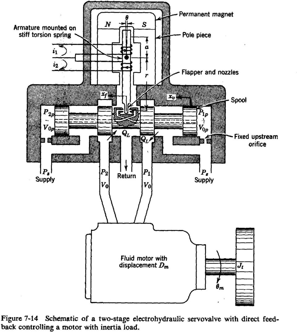
1 Electro-Hydraulic Servo Valve Construction, Models and Use From Merritt, H. E., Hydraulic Control Systems, J. Wiley, The input to an electro-hydraulic (EH) servovalve is typically a current or a differential current that powers an electromagnetic torque motor. The differential current Δi is typically supplied by an amplifier to avoid excess loading of the interface to the computer or controller. In the simplest (but not typical) form, the torque motor moves a spool valve as shown below. The spool valve allows the hydraulic fluid to pass from the supply to the return across two variable metering orifices with a controlled flow rate Q L. If the spool is shifted in the other direction the direction of flow will reverse. Since the clearances between the spool and the valve body is small, the forces required to move a large spool are large. Hence the single stage or direct acting EH valve is limited to low rates of flow (small valves). Figure 7-11 from Merritt shows the pictorial representation of the motion system in this case. In order to achieve higher flow rates, a two or three stage servovalve may be necessary. In this case the torque motor controls the first stage valve that actuates the spool on the second stage. The first stage valve is typically not a spool valve but either a flappernozzle valve or a jet pipe valve. The flapper-nozzle is more common. For these valves
 form, the torque motor moves a spool valve as shown below.")
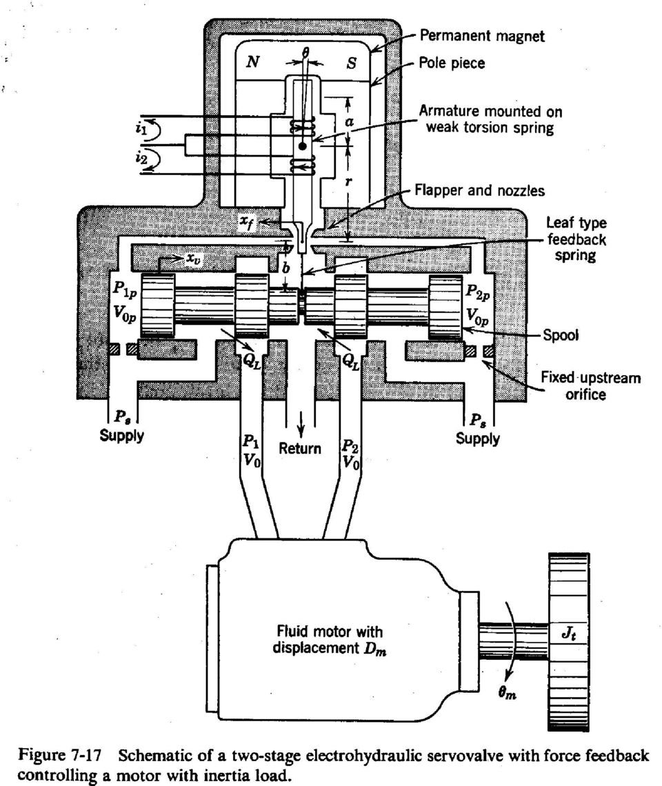
2 flow passes from the nozzle through a cylindrical area between the nozzle and the flat flapper that is near to it. As shown in Fig 7-14 and 7-17 from Merritt, the EH valve uses one flapper between two nozzles to produce a differential pressure that is applied to each side of the spool. The displacement of the flapper from a neutral position is powered by the torque motor and resisted by a torsional spring. The fixed upstream orifice in both types of valve is important to allow the pressure on either end of the spool to be below the supply pressure. A small flapper motion creates an imbalanced pressure in one direction or the other on the ends of the spool of the second stage. Obviously the spool will tend to move in response to this imbalance and allow flow Q L to the actuator. Since continued imbalance in pressure would quickly move the spool to its limits of travel, a form of feedback connects the motion of the spool to the effective displacement of the flapper. A very small spool displacement will result in a large flow at high pressures typically used. Two common forms of feedback are illustrated in the figures from Merritt. Direct position feedback moves the nozzle with the spool as shown in Fig Thus the equilibrium position of the spool is 1:1 with the position of the flapper. Fig 1-17 shows the force feedback arrangement in which a feedback leaf spring applies a force to the flapper to restore equilibrium. The ratio between the spring constant of this spring and the torsional spring on the torque motor determine the ratio between motion of the flapper and the spool. Valve Models Mathematical models of the EH valve can be constructed at various levels of detail depending on the purpose of the model. The models may represent the nonlinear square root relation between pressure and flow, or may be linearized about an operating position. When designing the valve itself, a more detailed model is typically required than when modeling the system controlled by a well designed valve. The model of the dynamics of the electromagnetic behavior is typically ignored or aggregated into the overall valve behavior, for example. Block diagram 7-18 shows a very detailed model of the force feedback valve that is simplified in the block diagram of Fig 8-5 constructed for analysis of the valve in a position control system. The transfer function of Equation (8-17) excerpted from Merritt is further simplified. This is the form you should hope to apply to a system design. Some of the parameters of this model are readily calculated, provided by the manufacturer or obtained from manufacturer s specifications. Other terms in (8-17) are better identified from aggregate measurements of the system s overall behavior. Even in this case it is generally desirable to compare the identified parameters to estimates based on first principles. The effective bulk modulus β e is an example. It depends not only on the compressibility of the pure fluid, but the effect of entrained air and vapor and the expansion of the walls containing a fluid. These effects are very hard to compute directly but they result in an increased compressibility (decrease bulk modulus), so the limiting case can be estimated from knowledge of the ideal properties.

3
4
5 The most common model of the load used for system design assumes the load is essentially an inertia and that = s s s n T s V D x D h h n L ce e t m ce v m q m ω δ ω β θ where the variables are given below, along with the units in the metric system:

6 θ = motor rotation, rad D x V valve flow gain, liters/mm = motor displacement, liters/rad = valve spool displacement, mm 3 = leakage coefficient, (m /sec)/(n/m = = volume compressed by fluid exiting valve, m β = system effective bulk modulus, N/m T m v t e L = externally applied load torque (N - m) n = gear ratio, ω = h natural frequency of hydaulic system, rad/sec δ = damping ratio of hydraulic system (sometimes labeledξ ), dimensionless h q m ce s = Laplace variable,1/sec motor rotation/controlled rotation, dimensionless ) Possible simplifications, refinements and extensions of this model are numerous: o The simplest valve model would give the steady state flow for a given electrical input. As one can see from the final value theorem and the blocks representing the valve in Merritt s Figure 8-5, for a step input (i.e. θ e ( s) = 1/ s ) to the error signal, lim s x ( s) = lim x ( t) = 1 = (a constant gain) x (input amplitude) v s 0 t v e d s Thus if the valve dynamics are fast compared to those of the load, one can essentially ignore the dynamics of the electrical drive and the electromagnetics of the valve, leaving the effect of the valve as a constant. o A more accurate model of the servo valve spool motion is given by a first or second order transfer function. The Merritt model shows a fourth order model for the electrical drive and spool dynamics but today s electrical drives are so fast that their dynamics may be ignored. See the Moog Company s venerable publication, Transfer Function for Moog Servovalves by Thayer for example models and parameters for a high performance servo valve. o For an example extension, consider T L which is shown in the block diagram as an external input, when it is likely to be dependent on the flow through the valve. This would be represented with a feedback loop representing the effects of inertia, compliance, damping, etc. of the load. o There are other connections that are of interest. The pressure in the actuator will reduce the pressure drop across the valve orifice. This effect is not explicit in the block diagram and would require further considerations of the back pressure if it is a substantial fraction of the supply pressure. Identification of Hydraulic System Parameters The model requires coefficients to be known within reasonable accuracy to be of any value. Some of the values can be measured directly, such as lengths and volumes. Other 3

7 parameters may be determined in groups by certain experiments. This is particularly true of the valve model. To identify the parameters of any dynamic experiments, a number of experiments can be performed. They include steady state measurements, time-domain measurements such as step responses, and frequency response measurements either from sinusoidal or other inputs. Often these experiments identify a coefficient of the transfer function that is a grouping of physical constants. In most cases it may be desirable to check the identified coefficients with the feasible range of values of the physical constants. One difficulty is the measurement in an open loop fashion due to the presence of a pure integrator in the system. Small amounts of flow through the valve in the null position cause the position to drift to the limits of travel. One alternative is to provide a position feedback which eliminates the drift although it alters the response. The true response has to be back calculated in these circumstances.

8 MOOG INC. CONTROLS DIVISION, EAST AURORA, NY 1405 TRANSFER FUNCTIONS FOR MOOG SERVOVALVES W. J. THAYER, DECEMBER 1958 Rev. JANUARY 1965 INTRODUCTION It is often convenient in servoanalysis or in system synthesis work to represent an electrohydraulic servovalve by a simplified, equivalent transfer function. Such a representation is, at best, only an approximation of actual servovalve performance. However, the usefulness of linear transfer functions for approximating servovalve response in analytical work is well established. The difficulty in assuming an explicit transfer function for electrohydraulic servovalves is that many design factors and many operational and environmental variables produce significant differences in the actual dynamic response. Consider the variables of the valve design. It is well known that internal valve paramaters (e.g., nozzle and orifice sizes, spring rates, spool diameter, spool displacement, etc.) may be adjusted to produce wide variations in dynamic response. An analytic approach for relating servovalve dynamic response to internal valve parameters is given in Appendix I of this technical bulletin. Once a servovalve is built, the actual dynamic response will vary somewhat with operating conditions such as supply pressure, input signal level, hydraulic fluid temperature, ambient temperature, valve loading, and so forth. These effects are insignificant for small variations about design values, but should be considered where wide excursions are anticipated. It is important to appreciate and control these and other operational variables when performing measurements of servovalve dynamics. If such precautions are not taken, misleading and inaccurate results may be obtained. Appendix II to this Bulletin describes the production

9 equipment presently used by Moog to measure servovalve dynamic response. Another difficulty in assigning simplified, linear transfer functions to represent servovalve response is that these valves are highly complex devices that exhibit high-order, nonlinear responses. If a first, second, or even third-order transfer function is selected to represent servovalve dynamics, still only an approximation to actual response is possible. Fortunately, for most physical systems, the servovalve is not the primary dynamic element, so it is only necessary to represent valve response throughout a relatively low frequency spectrum. For instance, if a servovalve-actuator is coupled to a load which exhibits a 50 cps resonant frequency, it is meaningful only to represent valve dynamic response in the frequency range to 50 cps. Similarly, for lower response physical systems, the contribution of valve dynamics throughout a correspondingly smaller frequency range need be considered. This simplification of actual servo response should be applied whenever practicable, for the reduced analytical task associated with the system analysis is obvious. These approximations to servovalve response have resulted in such expressions as "the equivalent time constant of the servovalve is - seconds" or "the apparent natural frequency of the servovalve is - radians /second." If a representation of servovalve response throughout the frequency range to about 50 cps is sufficient, then a first-order expression is usually adequate. Figure I shows a typical valve dynamic response, together with the response of a first-order transfer function. The first-order approximation is seen to be quite good throughout the lower frequency region. The time constant for the first-order transfer function (i.e., the equivalent servovalve time constant) is best established by curve fitting techniques. If a quick approximation is desired, the equivalent time constant should correspond to the 45 phase point rather than the 0.7

10 amplitude point (-3 db). In general, these points will not coincide as the higherorder dynamic effects contribute low frequency phase lag in the servovalve response, while not detracting appreciably from the amplitude ratio. If servovalve response to frequencies near the 90 phase lag point is of interest, then a second-order response should be used. In a positional servomechanism, a second-order representation of the servovalve response is usually sufficient, as the actuator contributes an additional 90 phase lag from the inherent integration. Figure shows a second-order approximation to the servovalve dynamics of Figure 1. Here, the natural frequency is best associated with the 90 phase point, and the damping ratio with the amplitude characteristic. Other factors will often weigh more heavily in the choice of an approximate natural frequency and damping ratio. For example, it may be desirable to approximate the low frequency phase characteristic accurately and, to do so, a secondorder transfer function which does not correlate with the 90 phase point may be used. A good deal of judgment must, therefore, be exercised to select the most appropriate transfer function approximation. FLOW CONTROL SERVOVALVES This basic servovalve is one in which the control flow at constant load is proportional to the electrical input current. Flow from these servovalves will be influenced in varying degrees by changing load pressures, as indicated in Figure 4. For null stability considerations, only the region of this plot about the origin need be considered. Here, the influence of the load on flow gain of the servovalve can be considered negligible. In general, the assumption of zero load influence is conservative with respect to system stability analyses. FIGURE 4 i Q P T W r S TO ACTUATOR TORQUE FIGURE 3 SYMBOLS FREQUENTLY USED VALVE SPOOL MOTOR differential current m a input to servovalve servovalve flow in /sec (cis) to the load servovalve differential Ibs/in (psi) pressure output servovalve sensitivity, as defined time constants natural frequencies damping ratios Laplace operator sec. rad/sec. nondimensional SERVOVALVE TRANSFER FUNCTIONS Appropriate transfer functions for standard Moog servovalves are given below. These expressions are linear, empirical relationships which approximate the response of actual servovalves when operating without saturation. The time constants, natural frequencies, and damping ratios cited are representative; however, the response of individual servovalve designs may vary quite widely from those listed. Nevertheless, these representations are very useful for analytical studies and can reasonably form the basis for detailed system design. Another linearity assumption which is often made is that servovalve flow gain is constant through null. This is theoretically true for an ideal zero lap null cut of the valve spool; however, the actual lap condition will vary with production tolerances. If the spool becomes overlapped, the servovalve flow gain is reduced at null. Likewise, an underlap produces higher-than-normal servovalve gain. Normal production tolerances maintained at Moog hold the spool lap within ±O.OOOl inch for all four null edges. This close control gives a very small range of possible nonlinear flow control through null (about ±3% for an axis null cut); but within this range, flow gain may be from 50% to 00% of nominal. The change in servovalve flow gain at null may sometimes cause system instability; or, in other cases, poor positioning accuracy, or poor dynamic response of the actuator at low-amplitude input signals. This situation can be varied one way or the other by holding a nominal overlap or underlap, as appropriate. The dynamic response of Moog flow control servovalves can be approximated in the frequency range to about 50 cps by the following first-order expression: 3

11 +W= (l ;,,> where -= servovalve static flow gain at zero load pressure drop 7 = apparent servovalve time constant cis m a set Standard flow control servovalves are available in several sizes and with many internal design configurations. The value of servovalve sensitivity depends upon the rated flow and input current. Typically, for a 5 gpm valve at a rated 8 ma input current, =.4 cis/ma. The appropriate time constant for representing servovalve dynamics will depend largely upon the flow capacity of the valve. Typical time constant approximations for Moog Type 30 servovalves are given in the table below. If it is necessary to represent servovalve dynamics through a wider frequency range, a second-order response can be used, as: The first and second-order transfer function approximations for servovalve dynamic response listed in the above table give reasonably good correlation with actual measured response. It is possible to relate servovalve response to internal valve parameters, as discussed in Appendix I. However, the analytical approach to servovalve dynamics is most useful during preliminary servovalve design, or when attempting to change the response of a given design. It is better, and more accurate, for system design to use empirical approximations of the measured servovalve response. PRESSURE CONTROL SERVOVALVES TORQUE MOTOR P VALVE SPOOL PRESSURE AC sensing the relationship of load pressure to input current. A second-order transfer function closely approximates the measured response in the frequency range to about 00 cps. + (s) =, where [1+(%ls+(%)j, = pressure control servovalve static gain Wn = n f, apparent natural frequency psi/ma rad/sec < = apparent damping ratio nondimensional where (J, = 7r f, apparent natural frequency 5 = apparent damping ratio nd Order fn cpr rad/sec t; FIGURE 5 TO ACTUATOR These servovalves provide a differential pressure output in response to the electrical input current. The static flowpressure curves for a typical pressure control servovalve are shown ill Figure 6. A small droop, or decrease in the controlled pressure with flow, does occur, even throughout the null region. This droop is usually small in pressure-control servovalves; however, in some applications even a small droop can significantly alter the system response. In pressureflow servovalves, droop is purposely introduced. Transfer functions for these valves are discussed in the next section. FIGURE 6 The controlled differential pressure may be any rated maximum up to the system pressure. For a 1000 psi rated control pressure at 8 ma electrical input,, = 15 psi/ma. With a blocked load, the apparent natural frequency for pressure control servovalves is approximately 50 cps, and the damping ratio is about 0.3 to 0.5. The actual blocked-load response for a pressure-control servovalve depends somewhat on the entrapped oil volume of the load, so the load volume should be noted with response data. It is convenient to measure the dy- When a pressure control servovalve is namic response of a pressure control required to supply flow to the load, the servovalve by capping the load lines and blocked-load transfer function no longer 4

12 APPENDIX I ANALYTIC ANALYSIS OF SERVOVALVE DYNAMICS It is possible to derive meaningful transfer functions for electrohydraulic servovalves, and several papers have reported such work (ref). Unfortunately, servovalves are complex devices and have many nonlinear characteristics which are significant in their operation. These nonlinearities include: electrical hysteresis of the torque motor, change in torque-motor output with displacement, change in orifice fluidimpedance with flow and with fluid characteristics, change in orifice discharge coefficient with pressure ratio, sliding friction of the spool, and others. Many servovalve parts are small so have a shape which is analytically nonideal. For example, fixed inlet orifices are often to inch in diameter. Ideally, the length of the orifice would be small with respect to its diameter to avoid both laminar and sharp-edge orifice effects; however, this becomes physically impractical with small orifices due to lack of strength for differential pressure loading, and lack of material for adequate life with fluid erosion. Therefore, the practical design from the performance standpoint is not necessarily the ideal design from the analytical standpoint. Experience has shown that these nonlinear and non-ideal characteristics limit the usefulness of theoretical analysis of servovalve dynamics in systems design. Instead, the more meaningful approach is to approximate measured servovalve response with suitable transfer functions, as discussed in the body of this technical bulletin. The analytic representation of servovalve dynamics is useful during preliminary design of a new valve configuration, or when attempting to alter response of a given design by parameter variation. Analysis also contributes to a clearer understanding of servovalve operation. Rather elaborate analyses of servovalve dynamic response have been performed at Moog, including computer studies which involve several nonlinear effects, and up to eight dynamic orders (excluding any load dynamics). Unfortunately, these complex analyses have not contributed significantly to servovalve design due to uncertainties and inaccuracies associated with the higher-order effects. These analyses have been extremely useful when reduced to their simpler form. A very adequate transfer function representation for the basic Type 30 mechanical feedback servovalve is given in Figure 1. This simplified representation results from the following assumptions: FIGURE 1 1. An ideal current source (infinite impedance) is used.. Negligible load pressure exists. 3. All nonlinearities can either be approximated by linear dynamic effects, or can be neglected. 4. The armature/flapper can be represented as a simple lumpedparameter system. 5. Perturbation conditions can be applied to the hydraulic amplifier orifice characteristics. 6. Fluid compressibility and viscosity effects are negligible. 7. Motions of the flapper are small with respect to spool motion. 8. The forces necessary to move the spool are small with respect to the driving force available. The last assumption implies that the differential pressure across the spool is TORQUE SUMMATION ARMATURE-FLAPPER SPOOL i TORQUE 1 x HYDRAULIC r MOTOR AMPLIFIER I - f Q x s SPOOL FLOW Q i GAIN ζ s 1+ s+ ωn ωn A 1s 3 s FEEDBAC WIRE w SIMPLIFIED SERVOVALVE BLOC DIAGRAM

13 negligible during dynamic conditions. If so, then spool mass, friction, flow forces, and other spool force effects can be neglected. At first this assumption may seem unreasonable; but it can be shown to be quite valid, and the simplification which results more than justifies its use. The simplified block diagram is a third order system consisting of the armature/ flapper mass, damping and stiffness, together with the flow-integration effect of the spool. The spool, in this case, is analogous to the piston of a simple position servoloop. The rotational mass of the armature/ flapper is quite easy to calculate. The effective stiffness of the armature/flapper is a composite of several effects, the most important of which are the centering effect of the flexure tube, and the decentering effect of the permanent magnet flux. The latter is set by charge level of the torque motor, and is individually adjusted in each servovalve to meet prescribed dynamic response limits. The damping force on the armature/flapper is likewise a composite effect. Here, it is known from experience that the equivalent ζ is about 0.4. The hydraulic-amplifier orifice bridge reduces to a simple gain term with the assumptions listed earlier. This gain is the differential flow unbalance between opposite arms of the bridge, per increment of flapper motion. Internal loop gain of the servovalve is determined by the following parameters. The hydraulic amplifier flow gain,, can be related to nozzle parameters by the following: Any of the loop gain parameters can be altered to change servovalve response. For example, the following changes would increase internal servovalve loop gain: (1) smaller spool diameter, () larger nozzle diameter, (3) higher nozzle pressure drop, (4) higher torque motor charge level. The higher torque motor charge gives a lower k f which increases loop gain, but this also lowers the natural frequency of the first stage. Unfortunately, the directions of these two effects are not compatible in that higher loop gain cannot be used with a lower natural frequency first stage. Therefore, an optimum charge level exists which produces maximum loop gain for the stability margin desired.

Manufacturing Equipment Modeling
 QUESTION 1 For a linear axis actuated by an electric motor complete the following: a. Derive a differential equation for the linear axis velocity assuming viscous friction acts on the DC motor shaft, leadscrew,
Chapter 11 SERVO VALVES. Fluid Power Circuits and Controls, John S.Cundiff, 2001
 Chapter 11 SERVO VALVES Fluid Power Circuits and Controls, John S.Cundiff, 2001 Servo valves were developed to facilitate the adjustment of fluid flow based on the changes in the load motion. 1 Typical
ENERGY TRANSFER SYSTEMS AND THEIR DYNAMIC ANALYSIS
 ENERGY TRANSFER SYSTEMS AND THEIR DYNAMIC ANALYSIS Many mechanical energy systems are devoted to transfer of energy between two points: the source or prime mover (input) and the load (output). For chemical
Proportional and Servo Valve Technology
 The ability to achieve automated stepless control of pressure and flow rate in fluid power systems has undergone major development in the past twenty-five years. Electrohydraulic servo valves were invented
System Modeling and Control for Mechanical Engineers
 Session 1655 System Modeling and Control for Mechanical Engineers Hugh Jack, Associate Professor Padnos School of Engineering Grand Valley State University Grand Rapids, MI email: [email protected] Abstract
CORRECTION OF DYNAMIC WHEEL FORCES MEASURED ON ROAD SIMULATORS
 Pages 1 to 35 CORRECTION OF DYNAMIC WHEEL FORCES MEASURED ON ROAD SIMULATORS Bohdan T. Kulakowski and Zhijie Wang Pennsylvania Transportation Institute The Pennsylvania State University University Park,
COUNTERBALANCE VALVES
 COUNTERBALANCE VALVES Introduction They are modulating valves which allow free flow into the actuator and then block the reverse flow until they feel a pilot pressure inversely proportional to the load
Michael Montgomery Marketing Product Manager Rosemount Inc. Russ Evans Manager of Engineering and Design Rosemount Inc.
 ASGMT / Averaging Pitot Tube Flow Measurement Michael Montgomery Marketing Product Manager Rosemount Inc. Russ Evans Manager of Engineering and Design Rosemount Inc. Averaging Pitot Tube Meters Introduction
13 ELECTRIC MOTORS. 13.1 Basic Relations
 13 ELECTRIC MOTORS Modern underwater vehicles and surface vessels are making increased use of electrical actuators, for all range of tasks including weaponry, control surfaces, and main propulsion. This
D634-P Series Direct Drive Proportional Valve with Integrated 24 V Electronics ISO 4401 Size 05
 D634-P Series Direct Drive Proportional Valve with Integrated 24 V Electronics ISO 4401 Size 05 GENERAL SECTION PAGE MOOG SERVO- AND PROPORTIONAL CONTROL VALVES General 2 enefits and Functionality 3 General
Understanding Poles and Zeros
 MASSACHUSETTS INSTITUTE OF TECHNOLOGY DEPARTMENT OF MECHANICAL ENGINEERING 2.14 Analysis and Design of Feedback Control Systems Understanding Poles and Zeros 1 System Poles and Zeros The transfer function
Dimensional analysis is a method for reducing the number and complexity of experimental variables that affect a given physical phenomena.
 Dimensional Analysis and Similarity Dimensional analysis is very useful for planning, presentation, and interpretation of experimental data. As discussed previously, most practical fluid mechanics problems
Active Vibration Isolation of an Unbalanced Machine Spindle
 UCRL-CONF-206108 Active Vibration Isolation of an Unbalanced Machine Spindle D. J. Hopkins, P. Geraghty August 18, 2004 American Society of Precision Engineering Annual Conference Orlando, FL, United States
EDUMECH Mechatronic Instructional Systems. Ball on Beam System
 EDUMECH Mechatronic Instructional Systems Ball on Beam System Product of Shandor Motion Systems Written by Robert Hirsch Ph.D. 998-9 All Rights Reserved. 999 Shandor Motion Systems, Ball on Beam Instructional
D660 Series Servo-Proportional Control Valves with Integrated Electronics ISO 4401 Size 05 to 10
 D660 Series Servo-Proportional Control Valves with Integrated Electronics ISO 4401 Size 05 to 10 OVERVIEW D660 Section Page MOOG SERVO-PROPORTIONAL CONTROL VALVES Overview 2 3 Technical Data 4 5 Electronics
Centrifugal Fans and Pumps are sized to meet the maximum
 Fans and Pumps are sized to meet the maximum flow rate required by the system. System conditions frequently require reducing the flow rate. Throttling and bypass devices dampers and valves are installed
Chapter 10. Flow Rate. Flow Rate. Flow Measurements. The velocity of the flow is described at any
 Chapter 10 Flow Measurements Material from Theory and Design for Mechanical Measurements; Figliola, Third Edition Flow Rate Flow rate can be expressed in terms of volume flow rate (volume/time) or mass
FLOW MEASUREMENT 2001 INTERNATIONAL CONFERENCE DERIVATION OF AN EXPANSIBILITY FACTOR FOR THE V-CONE METER
 FLOW MEASUREMENT 200 INTERNATIONAL CONFERENCE DERIVATION OF AN EXPANSIBILITY FACTOR FOR THE V-CONE METER Dr D G Stewart, NEL Dr M Reader-Harris, NEL Dr R J W Peters, McCrometer Inc INTRODUCTION The V-Cone
Experiment # 3: Pipe Flow
 ME 05 Mechanical Engineering Lab Page ME 05 Mechanical Engineering Laboratory Spring Quarter 00 Experiment # 3: Pipe Flow Objectives: a) Calibrate a pressure transducer and two different flowmeters (paddlewheel
RANDOM VIBRATION AN OVERVIEW by Barry Controls, Hopkinton, MA
 RANDOM VIBRATION AN OVERVIEW by Barry Controls, Hopkinton, MA ABSTRACT Random vibration is becoming increasingly recognized as the most realistic method of simulating the dynamic environment of military
HEAVY OIL FLOW MEASUREMENT CHALLENGES
 HEAVY OIL FLOW MEASUREMENT CHALLENGES 1 INTRODUCTION The vast majority of the world s remaining oil reserves are categorised as heavy / unconventional oils (high viscosity). Due to diminishing conventional
Steering unit. Table of contents. Features RE 11872/05.06. Type LAGL. Frame sizes 500 to 1000 Component series 1X Maximum flow 80 l/min
 Steering unit RE 11872/05.06 /10 Type LAGL Frame sizes 500 to 1000 Component series 1X Maximum flow 80 l/min H7375 Table of contents Contents Page Features 1 Ordering code 2 Function, section 3 Device
Flow divider (flow distributor), type TQ
, type TQ") Flow divider (flow distributor), type TQ Pressure p max = 0 bar Flow Q CN max = 00 lpm Share ratio = :. General Task Flow dividers type TQ are self-regulating valves, which largely irrespective of the
Flow divider (flow distributor), type TQ Pressure p max = 0 bar Flow Q CN max = 00 lpm Share ratio = :. General Task Flow dividers type TQ are self-regulating valves, which largely irrespective of the
Application Information
 Moog Components Group manufactures a comprehensive line of brush-type and brushless motors, as well as brushless controllers. The purpose of this document is to provide a guide for the selection and application
Unit - 6 Vibrations of Two Degree of Freedom Systems
 Unit - 6 Vibrations of Two Degree of Freedom Systems Dr. T. Jagadish. Professor for Post Graduation, Department of Mechanical Engineering, Bangalore Institute of Technology, Bangalore Introduction A two
du u U 0 U dy y b 0 b
 BASIC CONCEPTS/DEFINITIONS OF FLUID MECHANICS (by Marios M. Fyrillas) 1. Density (πυκνότητα) Symbol: 3 Units of measure: kg / m Equation: m ( m mass, V volume) V. Pressure (πίεση) Alternative definition:
DC motors: dynamic model and control techniques
 DC motors: dynamic model and control techniques Luca Zaccarian Contents 1 Magnetic considerations on rotating coils 1 1.1 Magnetic field and conductors.......................... 1 1.2 The magneto-motive
APPENDIX A CONTROL VALVE TESTING PROCEDURES AND EQUATIONS FOR LIQUID FLOWS
 APPENDIX A CONTROL VALVE TESTING PROCEDURES AND EQUATIONS FOR LIQUID FLOWS Section A.1. Flow Coefficients Definition The flow coefficient or pressure loss coefficient is used to relate the pressure loss
DCMS DC MOTOR SYSTEM User Manual
 DCMS DC MOTOR SYSTEM User Manual release 1.3 March 3, 2011 Disclaimer The developers of the DC Motor System (hardware and software) have used their best efforts in the development. The developers make
Experiment 3 Pipe Friction
 EML 316L Experiment 3 Pipe Friction Laboratory Manual Mechanical and Materials Engineering Department College of Engineering FLORIDA INTERNATIONAL UNIVERSITY Nomenclature Symbol Description Unit A cross-sectional
Controller Design in Frequency Domain
 ECSE 4440 Control System Engineering Fall 2001 Project 3 Controller Design in Frequency Domain TA 1. Abstract 2. Introduction 3. Controller design in Frequency domain 4. Experiment 5. Colclusion 1. Abstract
Drivetech, Inc. Innovations in Motor Control, Drives, and Power Electronics
 Drivetech, Inc. Innovations in Motor Control, Drives, and Power Electronics Dal Y. Ohm, Ph.D. - President 25492 Carrington Drive, South Riding, Virginia 20152 Ph: (703) 327-2797 Fax: (703) 327-2747 [email protected]
Force measurement. Forces VECTORIAL ISSUES ACTION ET RÉACTION ISOSTATISM
 Force measurement Forces VECTORIAL ISSUES In classical mechanics, a force is defined as "an action capable of modifying the quantity of movement of a material point". Therefore, a force has the attributes
TECHNICAL INFORMATION Bulletin
 Peerless Pump Company 2005 Dr. M.L. King Jr. Street, P.O. Box 7026, Indianapolis, IN 46207-7026, USA Telephone: (317) 925-9661 Fax: (317) 924-7338 www.peerlesspump.com www.epumpdoctor.com TECHNICAL INFORMATION
Unsteady Pressure Measurements
 Quite often the measurements of pressures has to be conducted in unsteady conditions. Typical cases are those of -the measurement of time-varying pressure (with periodic oscillations or step changes) -the
Slide 10.1. Basic system Models
 Slide 10.1 Basic system Models Objectives: Devise Models from basic building blocks of mechanical, electrical, fluid and thermal systems Recognize analogies between mechanical, electrical, fluid and thermal
Material taken from Fluid Power Circuits and Controls, John S. Cundiff, 2001
 Pressure Control Chapter 3 Material taken from Fluid Power Circuits and Controls, John S. Cundiff, 2001 Introduction Pressure control is a key element in the design of any circuit. Used correctly, it can
Dynamic Process Modeling. Process Dynamics and Control
 Dynamic Process Modeling Process Dynamics and Control 1 Description of process dynamics Classes of models What do we need for control? Modeling for control Mechanical Systems Modeling Electrical circuits
Physics 9e/Cutnell. correlated to the. College Board AP Physics 1 Course Objectives
 Physics 9e/Cutnell correlated to the College Board AP Physics 1 Course Objectives Big Idea 1: Objects and systems have properties such as mass and charge. Systems may have internal structure. Enduring
INSTRUMENTATION AND CONTROL TUTORIAL 3 SIGNAL PROCESSORS AND RECEIVERS
 INSTRUMENTATION AND CONTROL TUTORIAL 3 SIGNAL PROCESSORS AND RECEIVERS This tutorial provides an overview of signal processing and conditioning for use in instrumentation and automatic control systems.
Loudspeaker Parameters. D. G. Meyer School of Electrical & Computer Engineering
 Loudspeaker Parameters D. G. Meyer School of Electrical & Computer Engineering Outline Review of How Loudspeakers Work Small Signal Loudspeaker Parameters Effect of Loudspeaker Cable Sample Loudspeaker
Basic Op Amp Circuits
 Basic Op Amp ircuits Manuel Toledo INEL 5205 Instrumentation August 3, 2008 Introduction The operational amplifier (op amp or OA for short) is perhaps the most important building block for the design of
THE COMPOSITE DISC - A NEW JOINT FOR HIGH POWER DRIVESHAFTS
 THE COMPOSITE DISC - A NEW JOINT FOR HIGH POWER DRIVESHAFTS Dr Andrew Pollard Principal Engineer GKN Technology UK INTRODUCTION There is a wide choice of flexible couplings for power transmission applications,
Head Loss in Pipe Flow ME 123: Mechanical Engineering Laboratory II: Fluids
 Head Loss in Pipe Flow ME 123: Mechanical Engineering Laboratory II: Fluids Dr. J. M. Meyers Dr. D. G. Fletcher Dr. Y. Dubief 1. Introduction Last lab you investigated flow loss in a pipe due to the roughness
Positive Feedback and Oscillators
 Physics 3330 Experiment #6 Fall 1999 Positive Feedback and Oscillators Purpose In this experiment we will study how spontaneous oscillations may be caused by positive feedback. You will construct an active
Unit 24: Applications of Pneumatics and Hydraulics
 Unit 24: Applications of Pneumatics and Hydraulics Unit code: J/601/1496 QCF level: 4 Credit value: 15 OUTCOME 2 TUTORIAL 3 HYDRAULIC AND PNEUMATIC MOTORS The material needed for outcome 2 is very extensive
Differential Relations for Fluid Flow. Acceleration field of a fluid. The differential equation of mass conservation
 Differential Relations for Fluid Flow In this approach, we apply our four basic conservation laws to an infinitesimally small control volume. The differential approach provides point by point details of
E4E PILOT OPERATED DIRECTIONAL CONTROL VALVE WITH ELECTRIC PROPORTIONAL CONTROL SERIES 51
 83 300/100 ED E4E PILOT OPERATED DIRECTIONAL CONTROL VALVE WITH ELECTRIC PROPORTIONAL CONTROL SUBPLATE MOUNTING CETOP P05 p max 250 bar Q max (see specification table) MOUNTING INTERFACE OPERATING PRINCIPLE
Schematic Symbols Chart (Design Hydraulic and Pneumatic circits)
") Page 1 of 6 (Home) Symbols / Visit us on: Fluid Power, Automation and Motion Control for all Industries About Us Products Services Catalogs Place an Order Training & Information Contact Us Employee Access
Page 1 of 6 (Home) Symbols / Visit us on: Fluid Power, Automation and Motion Control for all Industries About Us Products Services Catalogs Place an Order Training & Information Contact Us Employee Access
Available online at www.sciencedirect.com Available online at www.sciencedirect.com
 Available online at www.sciencedirect.com Available online at www.sciencedirect.com Procedia Procedia Engineering Engineering () 9 () 6 Procedia Engineering www.elsevier.com/locate/procedia International
5. Measurement of a magnetic field
 H 5. Measurement of a magnetic field 5.1 Introduction Magnetic fields play an important role in physics and engineering. In this experiment, three different methods are examined for the measurement of
Application of the Orifice Meter for Accurate Gas Flow Measurement page 1. Application of the Orifice Meter for Accurate Gas Flow Measurement.
 Application of the Orifice Meter for Accurate Gas Flow Measurement page 1 DANIEL MEASUREMENT AND CONTROL WHITE PAPER Application of the Orifice Meter for Accurate Gas Flow Measurement www.daniel.com Summary
Introduction. Chapter 1. 1.1 The Motivation
 Chapter 1 Introduction 1.1 The Motivation Hydroelectric power plants, like real systems, have nonlinear behaviour. In order to design turbine controllers, it was normal practice in the past, when computer
Shaft. Application of full spectrum to rotating machinery diagnostics. Centerlines. Paul Goldman, Ph.D. and Agnes Muszynska, Ph.D.
 Shaft Centerlines Application of full spectrum to rotating machinery diagnostics Benefits of full spectrum plots Before we answer these questions, we d like to start with the following observation: The
Applications of Second-Order Differential Equations
 Applications of Second-Order Differential Equations Second-order linear differential equations have a variety of applications in science and engineering. In this section we explore two of them: the vibration
E. K. A. ADVANCED PHYSICS LABORATORY PHYSICS 3081, 4051 NUCLEAR MAGNETIC RESONANCE
 E. K. A. ADVANCED PHYSICS LABORATORY PHYSICS 3081, 4051 NUCLEAR MAGNETIC RESONANCE References for Nuclear Magnetic Resonance 1. Slichter, Principles of Magnetic Resonance, Harper and Row, 1963. chapter
Technical Guide No. 100. High Performance Drives -- speed and torque regulation
 Technical Guide No. 100 High Performance Drives -- speed and torque regulation Process Regulator Speed Regulator Torque Regulator Process Technical Guide: The illustrations, charts and examples given in
Chapter 8: Flow in Pipes
 Objectives 1. Have a deeper understanding of laminar and turbulent flow in pipes and the analysis of fully developed flow 2. Calculate the major and minor losses associated with pipe flow in piping networks
When the fluid velocity is zero, called the hydrostatic condition, the pressure variation is due only to the weight of the fluid.
 Fluid Statics When the fluid velocity is zero, called the hydrostatic condition, the pressure variation is due only to the weight of the fluid. Consider a small wedge of fluid at rest of size Δx, Δz, Δs
Soil Dynamics Prof. Deepankar Choudhury Department of Civil Engineering Indian Institute of Technology, Bombay
 Soil Dynamics Prof. Deepankar Choudhury Department of Civil Engineering Indian Institute of Technology, Bombay Module - 2 Vibration Theory Lecture - 8 Forced Vibrations, Dynamic Magnification Factor Let
Closed Loop Pressure Control for the Extrusion Process
 Closed Loop Pressure Control for the Extrusion Process By John Pacini Updated by Douglas Joy Extrusion is a continuous process and successful economic production depends on maintaining stable output and
Dynamics of Offshore Wind Turbines
 Proceedings of the Twenty-first (2011) International Offshore and Polar Engineering Conference Maui, Hawaii, USA, June 19-24, 2011 Copyright 2011 by the International Society of Offshore and Polar Engineers
Equivalent Spring Stiffness
 Module 7 : Free Undamped Vibration of Single Degree of Freedom Systems; Determination of Natural Frequency ; Equivalent Inertia and Stiffness; Energy Method; Phase Plane Representation. Lecture 13 : Equivalent
Pumps: Convert mechanical energy (often developed from electrical source) into hydraulic energy (position, pressure and kinetic energy).
 into hydraulic energy (position, pressure and kinetic energy).") HYDRAULIC MACHINES Used to convert between hydraulic and mechanical energies. Pumps: Convert mechanical energy (often developed from electrical source) into hydraulic energy (position, pressure and kinetic
HYDRAULIC MACHINES Used to convert between hydraulic and mechanical energies. Pumps: Convert mechanical energy (often developed from electrical source) into hydraulic energy (position, pressure and kinetic
Using Current Transformers with the 78M661x
 A Maxim Integrated Products Brand Using Current Transformers with the 78M661x APPLICATION NOTE AN_661x_021 April 2010 Introduction This application note describes using current transformers (CT) with the
Cancellation of Load-Regulation in Low Drop-Out Regulators
 Cancellation of Load-Regulation in Low Drop-Out Regulators Rajeev K. Dokania, Student Member, IEE and Gabriel A. Rincόn-Mora, Senior Member, IEEE Georgia Tech Analog Consortium Georgia Institute of Technology
Modeling Mechanical Systems
 chp3 1 Modeling Mechanical Systems Dr. Nhut Ho ME584 chp3 2 Agenda Idealized Modeling Elements Modeling Method and Examples Lagrange s Equation Case study: Feasibility Study of a Mobile Robot Design Matlab
Pressure Relief and Regulating Valves
 Pressure Relief and Regulating Valves With blocked center directional valves and variable displacement pumps, or open center directional valves and fixed displacement pumps where fast response, low leakage
Pump ED 101. Positive Displacement Pumps. Part I Reciprocating Pumps
 Pump ED 101 Positive Displacement Pumps Part I Reciprocating Pumps Joe Evans, Ph.D http://www.pumped101.com There are many pump designs that fall into the positive displacement category but, for the most
AP1 Oscillations. 1. Which of the following statements about a spring-block oscillator in simple harmonic motion about its equilibrium point is false?
 1. Which of the following statements about a spring-block oscillator in simple harmonic motion about its equilibrium point is false? (A) The displacement is directly related to the acceleration. (B) The
ANALYTICAL METHODS FOR ENGINEERS
 UNIT 1: Unit code: QCF Level: 4 Credit value: 15 ANALYTICAL METHODS FOR ENGINEERS A/601/1401 OUTCOME - TRIGONOMETRIC METHODS TUTORIAL 1 SINUSOIDAL FUNCTION Be able to analyse and model engineering situations
School of Engineering Department of Electrical and Computer Engineering
 1 School of Engineering Department of Electrical and Computer Engineering 332:223 Principles of Electrical Engineering I Laboratory Experiment #4 Title: Operational Amplifiers 1 Introduction Objectives
Mathematical Modeling and Dynamic Simulation of a Class of Drive Systems with Permanent Magnet Synchronous Motors
 Applied and Computational Mechanics 3 (2009) 331 338 Mathematical Modeling and Dynamic Simulation of a Class of Drive Systems with Permanent Magnet Synchronous Motors M. Mikhov a, a Faculty of Automatics,
Entrained Gas Diagnostic with Intelligent Differential Pressure Transmitter
 January Page Entrained Gas Diagnostic with Intelligent Differential Pressure Transmitter Dave Wehrs - Director, Pressure Engineering Andrew Klosinski - Application Engineer, Pressure Diagnostics Emerson
OPERATION MANUAL VALVE CHECKER G040-123
 OPERATION MANUAL VALVE CHECKER AUSTRALIA PTY. LTD. L:\DWG_NO\DOCUMENT\MANUALS\Word File\A OPERATION MANUAL CN 20.4.99 VALVE CHECKER 1 of 20 CONTENTS Chapter Title Page 1. Description 3 2. Specification
Series TMM Axial Piston Motor. Technical Information
 Series TMM Axial Piston Motor Technical Information General Description GENERAL DESCRIPTION These motors are designed primarily to be combined with other products in closed circuit systems to transfer
Mounting instructions. Acceleration Transducer B12. B 26.B12.10 en
 Mounting instructions Acceleration Transducer B12 B 26.B12.10 en B12 3 Contents Page Safety instructions.............................................. 4 1 Scope of supply..............................................
Fluid structure interaction of a vibrating circular plate in a bounded fluid volume: simulation and experiment
 Fluid Structure Interaction VI 3 Fluid structure interaction of a vibrating circular plate in a bounded fluid volume: simulation and experiment J. Hengstler & J. Dual Department of Mechanical and Process
Harmonic Drive acutator P r e c i s i o n G e a r i n g & M o t i o n C o n t r o l
 D C S e r v o S y s t e m s RH Mini Series Total Motion Control Harmonic Drive acutator P r e c i s i o n G e a r i n g & M o t i o n C o n t r o l Precision Gearing & Motion Control DC SERVO ACTUATORS
DEVELOPMENT OF A TWIN SCREW EXPRESSOR AS A THROTTLE VALVE REPLACEMENT FOR WATER-COOLED CHILLERS
 DEVELOPMENT OF A TWIN SCREW EXPRESSOR AS A THROTTLE VALVE REPLACEMENT FOR WATER-COOLED CHILLERS J J Brasz, Carrier Corporation, Syracuse, NY, 13221, USA [email protected] I K Smith and N Stosic
Considering the effects of UPS operation with leading power factor loads
 Considering the effects of UPS operation with leading power factor loads Over the past five years, a new generation of data processing and communications equipment has become prevalent in modern data centers
Acceleration levels of dropped objects
 Acceleration levels of dropped objects cmyk Acceleration levels of dropped objects Introduction his paper is intended to provide an overview of drop shock testing, which is defined as the acceleration
HOW ACCURATE ARE THOSE THERMOCOUPLES?
 HOW ACCURATE ARE THOSE THERMOCOUPLES? Deggary N. Priest Priest & Associates Consulting, LLC INTRODUCTION Inevitably, during any QC Audit of the Laboratory s calibration procedures, the question of thermocouple
Motor Selection and Sizing
 Motor Selection and Sizing Motor Selection With each application, the drive system requirements greatly vary. In order to accommodate this variety of needs, Aerotech offers five types of motors. Motors
Introduction to Engineering System Dynamics
 CHAPTER 0 Introduction to Engineering System Dynamics 0.1 INTRODUCTION The objective of an engineering analysis of a dynamic system is prediction of its behaviour or performance. Real dynamic systems are
FLUID FLOW Introduction General Description
 FLUID FLOW Introduction Fluid flow is an important part of many processes, including transporting materials from one point to another, mixing of materials, and chemical reactions. In this experiment, you
A descriptive definition of valve actuators
 A descriptive definition of valve actuators Abstract A valve actuator is any device that utilizes a source of power to operate a valve. This source of power can be a human being working a manual gearbox
INSTRUMENTATION AND CONTROL TUTORIAL 2 ELECTRIC ACTUATORS
 INSTRUMENTATION AND CONTROL TUTORIAL 2 ELECTRIC ACTUATORS This is a stand alone tutorial on electric motors and actuators. The tutorial is of interest to any student studying control systems and in particular
10 tips for servos and steppers a simple guide
 10 tips for servos and steppers a simple guide What are the basic application differences between servos and steppers? Where would you choose one over the other? This short 10 point guide, offers a simple
Select the Right Relief Valve - Part 1 Saeid Rahimi
 Select the Right Relief Valve - Part 1 Saeid Rahimi 8-Apr-01 Introduction Selecting a proper type of relief valve is an essential part of an overpressure protection system design. The selection process
EDEXCEL NATIONAL CERTIFICATE/DIPLOMA UNIT 5 - ELECTRICAL AND ELECTRONIC PRINCIPLES NQF LEVEL 3 OUTCOME 4 - ALTERNATING CURRENT
 EDEXCEL NATIONAL CERTIFICATE/DIPLOMA UNIT 5 - ELECTRICAL AND ELECTRONIC PRINCIPLES NQF LEVEL 3 OUTCOME 4 - ALTERNATING CURRENT 4 Understand single-phase alternating current (ac) theory Single phase AC
Heat Transfer Prof. Dr. Ale Kumar Ghosal Department of Chemical Engineering Indian Institute of Technology, Guwahati
 Heat Transfer Prof. Dr. Ale Kumar Ghosal Department of Chemical Engineering Indian Institute of Technology, Guwahati Module No. # 04 Convective Heat Transfer Lecture No. # 03 Heat Transfer Correlation
Example. Fluid Power. Circuits
 Example Fluid Power Circuits To Enhance Symbol Reading Skills To Work On Circuit Reading Skills With Answers HI LO Pump Circuit 18 A1 B1 17 16 15 13 Set 14 2,000 PSI PG2 Set 500 PSI 12 11 7 8 10 PG1 9
Tips For Selecting DC Motors For Your Mobile Robot
 Tips For Selecting DC Motors For Your Mobile Robot By AJ Neal When building a mobile robot, selecting the drive motors is one of the most important decisions you will make. It is a perfect example of an
Selecting and Sizing Ball Screw Drives
 Selecting and Sizing Ball Screw Drives Jeff G. Johnson, Product Engineer Thomson Industries, Inc. Wood Dale, IL 540-633-3549 www.thomsonlinear.com [email protected] Fig 1: Ball screw drive is a
2.161 Signal Processing: Continuous and Discrete Fall 2008
 MT OpenCourseWare http://ocw.mit.edu.6 Signal Processing: Continuous and Discrete Fall 00 For information about citing these materials or our Terms of Use, visit: http://ocw.mit.edu/terms. MASSACHUSETTS
Simple Harmonic Motion
 Simple Harmonic Motion 1 Object To determine the period of motion of objects that are executing simple harmonic motion and to check the theoretical prediction of such periods. 2 Apparatus Assorted weights