Pumps: Convert mechanical energy (often developed from electrical source) into hydraulic energy (position, pressure and kinetic energy).
|
|
|
- Rosanna Woods
- 8 years ago
- Views:
Transcription
1 HYDRAULIC MACHINES Used to convert between hydraulic and mechanical energies. Pumps: Convert mechanical energy (often developed from electrical source) into hydraulic energy (position, pressure and kinetic energy). Water turbines: Convert hydraulic energy to mechanical energy and mechanical energy is used to drive generators that develop electricity. Water turbines are generally designed and manufactured to each power stations own conditions of water head, discharge, water and power demands. Electrical energy-> MOTORS-> Mechanical Energy->PUMPS-> Hydraulic Energy (Input) (shaft power) (Output) Mechanical -> TURBINES-> Mechanical Energy->GENERATORS-> Electrical Energy Energy (Water, Input) (shaft power) (Output)

2 Pumps are available everywhere, applications are wide reaching. Principle: A vacuum is created in the working chamber by expelling air. The pressure on the fluid surface in the sump will then be higher than in the working chamber of the pump; thus fluid is lifted into the chamber by the pressure difference. The fluid will then be pushed to the delivery pipe either by displacement or under a pressure head. Role of civil engineers..

3

4

5 Small electric pump Positive displacement pumps Gear pump Positive displacement pumps have an expanding cavity on the suction side and a decreasing cavity on the discharge side. Liquid flows into the pumps as the cavity on the suction side expands and the liquid flows out of the discharge as the cavity collapses. The volume is constant given each cycle of operation.


6 Peristaltic pump Reciprocating pump


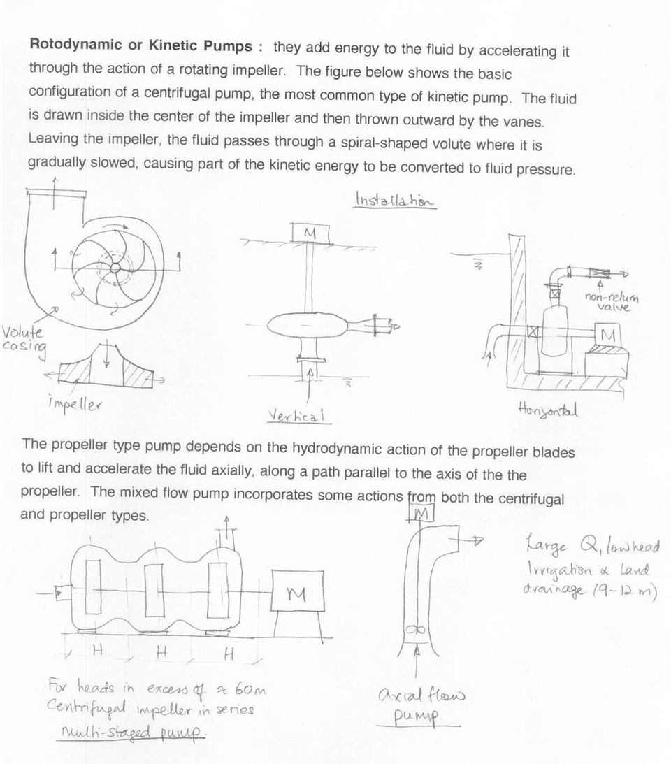
7 Velocity Pumps Rotodynamic pumps (or dynamic pumps) are a type of velocity pump in which kinetic energy added to the fluid by increasing the flow velocity. This increase in energy is converted to a gain in potential energy (pressure) when the velocity is reduced prior to or as the flow exits the pump into the discharge pipe. This conversion of kinetic energy to pressure can be explained by the First law of thermodynamics or more specifically by Bernoulli's principle. Centrifugal Pump Axial Flow Pump

8
9 Key features of Screw Centrifugal Impeller are: Energy savings of up to 50% compared with conventional centrifugal pumps. Same high efficiency maintained in Hidrostal s immersible, submersible and end suction pumps Non-clog impeller suitable for pumping high consistency media and large diameter solids beyond the capacity of centrifugal and recessed impeller pumps Easy adjustment of impeller clearance permits continuity of original high-efficiency performance Optional renewable liner to reduce maintenance costs when pumping abrasive media. Low N.P.S.H characteristics Available in choice of materials

10

11

12

13

14

15

16 Pump Efficiency e= output/input = water power /shaft power PumpEfficiency ( QH ) / ( TN) Q flowrate, capacity H totalhead( statichead losses) T torque of shaft N speed( rpm, rad / sec)
 T torque of shaft N speed( rpm, rad /")
17

18 SKETCH

19

20 Geometrically Similar Pumps Example: A model pump of 125 mm diameter develops 185W at a speed of 800 rpm under a head of 760 mm. A geometrically similar pump 380 mm diameter is to operate at the same efficiency at a head of 15 m. What speed and power should be expected?

21
22 Alterations to the Same Pump Example 2: A pump tested at 1800rpm gives the following results: capacity 253 l/s, head=48 m, power =141.7KW. A) Obtain the performance of this pump at 1600 rpm. B) If along with the speed the diameter of the impeller is reduced from 380 mm to 356 mm, obtain the revised pump characteristics.
23 Similarity Laws Again When the shaft horsepower supplied to a certain centrifugal pump is 25 hp, the pump discharges 700 gpm of water while operating at 1800 rpm with a head rise of 90 ft. A) If the pump speed is reduced to 1200rpm, determine the new head rise and shaft horsepower. Assume the efficiency remains the same. B) What is the specific speed (Ns) for this pump?
24
25
26 PUMP PERFROMANCE CHARACTERISTICS -The actual head rise is always less than the ideal head rise by an amount equal to the head loss. -SKETCH ideal / maximum head rise Head U g U cot 2 r b g Q -SKETCH effect of losses on flow rate curve Pump performance/characteristics curves: Actual head rise gained by fluid through a pump is determined through experiments and is usually given in plots of h a, efficiency, shaft speed and brake horsepower versus Q (capacity). Head developed at zero discharge is shutoff head. Total power applied to the shaft= Brake horsepower. Actual pump efficiency includes hydraulic losses, mechanical efficiency (in bearings and seals) and volumetric efficiency (due to leakage).
27 PUMP PERFORMANCE CURVES Different size pumps and 1 speed Single pump different speeds
28
29
30 SYSTEM HEAD CURVE- important for selection of a pump and it represents the behavior of the piping system. Hp H h h Hs h h f m s f m statichead frictionloss min orlosses For any piping system there are losses. Hp is used to calculate the power requirements for the pump. P QHp / e
31 SKETCH
32 SYSTEM HEAD CURVE For any given discharge a certain Hp must be supplied to maintain that flow. We can construct a Hp versus Q curve for each system. This is called the system curve. For any given centrifugal pump will have a head versus discharge curve. This is the characteristic curve at a given pump speed. This supplied by the manufacturer. SKETCH As discharge increases in a pipe the head required for the flow increases but the head produced by the pump decreases as discharge increases. The point of intersection is.
33 Example 1: What will be the discharge in this water system if the pump has the characteristics shown below. Q m3/s: Hp m: Assume Ke=0.5 and Kb=0.35, K E =1.0
34 Head (m) Example 1:Operating condition occurs at Q=0.27 m3/s Operating Point System Curve H versus Q Curve Pump Curve Q (m3/s)
35
36 Head (m), Efficiency (%) Example Q (L/s) Q (m3/s) Pump Curve Efficiency System Curve Operating point Q = 65 l/s, H=32 m, efficiency=68%, input Power= 30KW Efficiency System Curve Pump Curve Q (m3/s)
37 EXAMPLE 3: It is necessary to select a pump to deliver water from a source to a location 25 m higher in elevation. A 0.25 m diameter cast iron pipeline 1000 m long will be used. At the destination end of the pipe it is required that a pressure of 50,000 N/m2 be available. The required flow rate is 25 l/s and the water temperature is 20 degrees Celsius. Using the pump performance curves given below determine the optimum pump (hp) for this situation.
38 EXAMPLE 3: Solution Q (l/s) Q (m3/hr) H (m)
39 EXAMPLE 3: Solution Q (l/s) Q (m3/hr) H (m) m3/hr ~110 m3/hr
40 MULTIPLE PUMP SYSTEM A single pump is suitable within a narrow range of head and discharge in proximity of pump efficiency. However, in a piping system the discharge and head requirements may vary considerably at different times. Within a certain range, these fluctuations in head and discharge can be accommodated by adopting variable-speed motors. Pump characteristics can be altered by suitable adjustment of the speed. When the fluctuations are considerable or the head or capacity requirement is too high for a single pump, two or more pumps are used in series or parallel. It s advantageous from both a hydraulic and economic considerations to use pumps of identical size to match their performance characteristics. Pumps are used in series in a system where a substantial head changes take place without appreciable difference in the discharge (i.e. the system curve is steep). In series each pump has the same discharge. The parallel pumps are useful for systems with considerable discharge variations with no appreciable head change. In parallel, each pump has the same head.
41 PUMPS IN SERIES The following relations apply: H=Ha+Hb+ Hc+. Q=Qa=Qb=Qc η (efficiency)= (Ha+Hb+.) (Ha/η+Hb/η+ ) P Q( Ha Hb...) / Where a, b, c refer to different pumps. The composite head characteristics curve is prepared by adding the ordinates (heads) of all pumps for the same values of discharge. The intersection of the composite head characteristics curve and the system head provides the operating condition.
42 Head (m) SERIES EXAMPLE Same Q required but increased losses due to changes in system. Pump from example 1 in series System curve -1 Hp=30+127Q 2 System curve -2 Hp=30+600Q Pump System- System- Q Pump Pump1 Pump 1+2 System-1 System Q m3/s
43 PUMPS IN PARALLEL For pumps in parallel, the following relations apply: H=Ha=Hb= Hc=. Q=Qa+Qb+Qc η= (Qa+Qb+.) (Qa/η+Qb/η+ ) P H( Qa Qb...) / Where a, b, c refer to different pumps. The composite head characteristics curve is prepared by adding the abscissas (discharges) of all pumps for the same values of head. The intersection of the composite head characteristics curve and the system head provides the operating condition.
44 Head (m) PARALLEL EXAMPLE Larger capacity required for destination but less losses in system. Pump from example 1 in parallel System curve -1 Hp=30+127Q 2 System curve -2 Hp=30+60Q Parallel Pump- System- System- Pump Head Pump-1+2 Pump System-1 System Q (m3/s)
45 Limit on Pump Location (Net Positive Suction Head, NPSH) We have considered total head, capacity, power and efficiency requirements. Condition at the inlet of the pump is critical. Inlet or suction system must a smooth flow of fluid to enter the pump at sufficiently high pressure to avoid creating vapour bubbles in the fluid. As pressure on fluid decreases, temperature at which vapour bubbles form ( like boiling) also decreases. The suction pressure at the pump inlet must be above the pressure of vapourization for the operating temperature of the liquid. This is called providing Net Positive Suction Head. If suction pressure is allowed to decrease so vapourization occurs; cavitation is created in the pump. Pump will draw liquid and vapour, bubbles will collapse under pressure. = Noisy, vibration, wear on pump parts.
46 Pump location and Net Positive Suction Head, NPSH Pump manufacturers supply data about required net positive suction head for proper pump operation. We must select pumps that ensure sufficiently high NPSH is available. NPSHavailable> NPSH required NPSHavailable depends on: nature of fluid, suction piping, location of reservoir, pressure applied to fluid in the reservoir. NPSHa = hsp ± hs hf hvp (apply Bernoulli equation) hsp = static pressure head applied to fluid (in m or ft) hs = elevation difference from level of fluid in reservoir to pump inlet (in m or ft). hf = friction loss in suction piping hvp = vapour pressure of the liquid at the pumping temperature
47 Pump location and Net Positive Suction Head, NPSH Web sites: pump cavitating cavitation bubbles:
48 Pump location and Net Positive Suction Head, NPSH
49 Pump location and Net Positive Suction Head, NPSH
50 Pump location and Net Positive Suction Head, NPSH
51 Pump location and Net Positive Suction Head, NPSH
52 Pump location and Net Positive Suction Head, NPSH EXAMPLE
53 Pump location and Net Positive Suction Head, NPSH Given: Vapour pressure water at 70C= 31,200 N/m3 specific weight water at 70C = 9.59x10^3 N/m3 Kinematic viscosity water at 70C= 4.13x10^-7 m2/s Kelbow = ƒ x30 Kvalve= ƒx340 Kentrance= 1.0 Ε=4.6x10^-5 m


54 Pump location and Net Positive Suction Head, NPSH
55 Pump location and Net Positive Suction Head, NPSH EXAMPLE 4- elevation of pump A centrifugal pump is to be placed above a large, open water tank, as shown below. The pump is to pump water at a rate of 0.5 ft^3/s. At this flow rate the required NPSH is 15 ft, as specified by the pump manufacturer. The water temperature is 80 degrees F and atmospheric pressure is 14.7 psi. Assume that the major head loss between the tank and the pump inlet is due to a filter at the pipe inlet having minor loss coefficient K= 20. Other losses can be neglected. The pipe on the suction site of the pump has a diameter of 4 inches. Determine the max height (Z) that the pump can be located above the water surface without cavitation. If you were required to place a vale in the flow path would you put it upstream or downstream of the pump? Why?
56 Example Pumps in Series A pump with a pump performance curve hp=30-200q 2 where hp is in meters and Q is in m3/min is used to pump a fluid up a 25m high hill. The system equation is hp= Q 2. A) Determine the flow rate expected and operating head. B) Is this pump reasonable choice to use if the fluid is to be pumped up a 35m high hill (hp=35+100q 2 ). If not use 2 pumps in series. Determine the expected flow rate.
57 Example Pumps in Series Q Pump1 Pump 1+2 System-1 System
Practice Problems on Pumps. Answer(s): Q 2 = 1850 gpm H 2 = 41.7 ft W = 24.1 hp. C. Wassgren, Purdue University Page 1 of 16 Last Updated: 2010 Oct 29
: Q 2 = 1850 gpm H 2 = 41.7 ft W = 24.1 hp. C. Wassgren, Purdue University Page 1 of 16 Last Updated: 2010 Oct 29") _02 A centrifugal with a 12 in. diameter impeller requires a power input of 60 hp when the flowrate is 3200 gpm against a 60 ft head. The impeller is changed to one with a 10 in. diameter. Determine the
_02 A centrifugal with a 12 in. diameter impeller requires a power input of 60 hp when the flowrate is 3200 gpm against a 60 ft head. The impeller is changed to one with a 10 in. diameter. Determine the
CENTRIFUGAL PUMP OVERVIEW Presented by Matt Prosoli Of Pumps Plus Inc.
 CENTRIFUGAL PUMP OVERVIEW Presented by Matt Prosoli Of Pumps Plus Inc. 1 Centrifugal Pump- Definition Centrifugal Pump can be defined as a mechanical device used to transfer liquid of various types. As
Pump Selection and Sizing (ENGINEERING DESIGN GUIDELINE)
") Guidelines for Processing Plant Page : 1 of 51 Rev 01 Feb 2007 Rev 02 Feb 2009 Rev 03 KLM Technology #03-12 Block Aronia, Jalan Sri Perkasa 2 Taman Tampoi Utama 81200 Johor Bahru. (ENGINEERING DESIGN GUIDELINE)
Guidelines for Processing Plant Page : 1 of 51 Rev 01 Feb 2007 Rev 02 Feb 2009 Rev 03 KLM Technology #03-12 Block Aronia, Jalan Sri Perkasa 2 Taman Tampoi Utama 81200 Johor Bahru. (ENGINEERING DESIGN GUIDELINE)
CENTRIFUGAL PUMP SELECTION, SIZING, AND INTERPRETATION OF PERFORMANCE CURVES
 CENTRIFUGAL PUMP SELECTION, SIZING, AND INTERPRETATION OF PERFORMANCE CURVES 4.0 PUMP CLASSES Pumps may be classified in two general types, dynamic and positive displacement. Positive displacement pumps
= water horsepower WHP brake horsepower QH WHP = (222) ( 33,000 ft-lbs/min-hp)( 7.481 gal/ft ) 1 HP=0.746 kw
 ( 33,000 ft-lbs/min-hp)( 7.481 gal/ft ) 1 HP=0.746 kw") Lecture 11 Pumps & System Curves I. Pump Efficiency and Power Pump efficiency, E pump E pump = water horsepower WHP brake horsepower = BHP (221) where brake horsepower refers to the input power needed
Lecture 11 Pumps & System Curves I. Pump Efficiency and Power Pump efficiency, E pump E pump = water horsepower WHP brake horsepower = BHP (221) where brake horsepower refers to the input power needed
Module 9: Basics of Pumps and Hydraulics Instructor Guide
 Module 9: Basics of Pumps and Hydraulics Instructor Guide Activities for Unit 1 Basic Hydraulics Activity 1.1: Convert 45 psi to feet of head. 45 psis x 1 ft. = 103.8 ft 0.433 psi Activity 1.2: Determine
TOPIC: 191004 KNOWLEDGE: K1.01 [3.3/3.5] Which one of the following contains indications of cavitation in an operating centrifugal pump?
![TOPIC: 191004 KNOWLEDGE: K1.01 [3.3/3.5] Which one of the following contains indications of cavitation in an operating centrifugal pump?](/thumbs/17/105210.jpg "TOPIC: 191004 KNOWLEDGE: K1.01 [3.3/3.5] Which one of the following contains indications of cavitation in an operating centrifugal pump?") KNOWLEDGE: K1.01 [3.3/3.5] P21 Which one of the following contains indications of cavitation in an operating centrifugal pump? A. Low flow rate with low discharge pressure. B. Low flow rate with high discharge
KNOWLEDGE: K1.01 [3.3/3.5] P21 Which one of the following contains indications of cavitation in an operating centrifugal pump? A. Low flow rate with low discharge pressure. B. Low flow rate with high discharge
VERTICAL TURBINE AND PROPELLER PUMPS
 VERTICAL TURBINE AND PROPELLER PUMPS INTRODUCTION Vertical Turbine and Propeller Pumps Model 7000 Series Turbine Pump Model 800 Series Axial Flow Propeller Pump Model 800 Series Mixed Flow Propeller Pump
A BRIEF INTRODUCTION TO CENTRIFUGAL PUMPS
 A BRIEF INTRODUCTION TO CENTRIFUGAL PUMPS figure below is a cross section of a centrifugal pump and shows the two basic parts. Joe Evans, Ph.D IMPELLER This publication is based upon an introductory, half
Pump ED 101. Positive Displacement Pumps. Part I Reciprocating Pumps
 Pump ED 101 Positive Displacement Pumps Part I Reciprocating Pumps Joe Evans, Ph.D http://www.pumped101.com There are many pump designs that fall into the positive displacement category but, for the most
Centrifugal Fans and Pumps are sized to meet the maximum
 Fans and Pumps are sized to meet the maximum flow rate required by the system. System conditions frequently require reducing the flow rate. Throttling and bypass devices dampers and valves are installed
Selection Of Centrifugal Pumping Equipment 1
 Circular 1048 Selection Of Centrifugal Pumping Equipment 1 Dorota Z. Haman, Fedro S. Zazueta, Forrest T. Izuno 2 INTRODUCTION The pump is an essential component of an irrigation system. Proper selection
Twin Screw Technology. General Overview and Multiphase Boosting 11/2013. Calgary Pump Symposium 2013
 Twin Screw Technology General Overview and Multiphase Boosting 11/2013 Axel Jäschke Technical Director - ITT Bornemann USA Office: Mobile: +1 832 320 2500 +49 170 576 4115 +1 832 293 7935 1 Bio Axel Jäschke
FIXED DISPLACEMENT HYDRAULIC VANE PUMPS BQ SERIES
 BQ FIXED DISPLACEMENT HYDRAULIC VANE PUMPS BQ SERIES Versatility, power, compactness and low running costs are the main characteristics of B&C vane pumps. All the components subject to wear are contained
Pump Formulas Imperial and SI Units
 Pump Formulas Imperial and Pressure to Head H = head, ft P = pressure, psi H = head, m P = pressure, bar Mass Flow to Volumetric Flow ṁ = mass flow, lbm/h ρ = fluid density, lbm/ft 3 ṁ = mass flow, kg/h
FI Frame-Mounted End Suction Pumps
 Water Circulation Pumps & Circulators FI Frame-Mounted End Suction Pumps FI Series Pumps provide the ultimate in reliability and ease of installation for heating, air conditioning, pressure boosting, cooling
SJT / SJM / SJP Large Vertical Pumps
 SJT / SJM / SJP Large Vertical Pumps The Heart of Your Process SJT, SJM, SJP Large Vertical Pumps Product Overview SJT Turbine Ns 1800 < 5000 nq 35 < 110 SJM Mixed Flow Ns 5800 < 8300 nq 113 < 161 SJP
FIXED DISPLACEMENT HYDRAULIC VANE PUMPS BQ SERIES
 BQ FIXED DISPLACEMENT HYDRAULIC VANE PUMPS BQ SERIES Versatility, power, compactness and low running costs are the main characteristics of B&C vane pumps. All the components subject to wear are contained
FIXED DISPLACEMENT HYDRAULIC VANE PUMPS BQ SERIES
 BQ FIXED DISPLACEMENT HYDRAULIC VANE PUMPS BQ SERIES Versatility, power, compactness and low running costs are the main characteristics of B&C vane pumps. All the components subject to wear are contained
Minor losses include head losses through/past hydrants, couplers, valves,
 Lecture 10 Minor Losses & Pressure Requirements I. Minor Losses Minor (or fitting, or local ) hydraulic losses along pipes can often be estimated as a function of the velocity head of the water within
Vertical selfpriming Side-Channel Pumps Type WPV
 Vertical selfpriming Side-Channel Pumps Type WPV FIELD OF APPLICATION The side-channel pumps are selfpriming and operate more economically (better efficiency) than normal centrifugal pumps when handling
TECHNICAL INFORMATION Bulletin
 Peerless Pump Company 2005 Dr. M.L. King Jr. Street, P.O. Box 7026, Indianapolis, IN 46207-7026, USA Telephone: (317) 925-9661 Fax: (317) 924-7338 www.peerlesspump.com www.epumpdoctor.com TECHNICAL INFORMATION
Vertical Pumps for the Oil & Gas Industry
 Vertical Pumps for the Oil & Gas Industry ITT API Expert ITT Commitment ITT is committed to the Oil and Gas market, which is the largest segment of our business. We have been investing in technology to
C. starting positive displacement pumps with the discharge valve closed.
 KNOWLEDGE: K1.04 [3.4/3.6] P78 The possibility of water hammer in a liquid system is minimized by... A. maintaining temperature above the saturation temperature. B. starting centrifugal pumps with the
Unit 24: Applications of Pneumatics and Hydraulics
 Unit 24: Applications of Pneumatics and Hydraulics Unit code: J/601/1496 QCF level: 4 Credit value: 15 OUTCOME 2 TUTORIAL 3 HYDRAULIC AND PNEUMATIC MOTORS The material needed for outcome 2 is very extensive
BSM MOTOR DRIVEN CENTRIFUGAL PUMPS
 PRINCIPLE OF OPERATION A hydraulically and dynamically balanced impeller with raised vane sections discharges liquid as a result of the centrifugal force developed in rotation. The head developed is entirely
PEERLESS PUMP COMPANY SYSTEM ANALYSIS FOR PUMPING EQUIPMENT SELECTION
 PEERLESS PUMP COMPANY SYSTEM ANALYSIS FOR PUMPING EQUIPMENT SELECTION Peerless Pump Company 005 Dr. Martin Luther King Jr. Street P.O. Box 706 Indianapolis, Indiana 4607-706 Phone: (317) 95-9661 Fax: (317)
2. Parallel pump system Q(pump) = 300 gpm, h p = 270 ft for each of the two pumps
 = 300 gpm, h p = 270 ft for each of the two pumps") Pumping Systems: Parallel and Series Configurations For some piping system designs, it may be desirable to consider a multiple pump system to meet the design requirements. Two typical options include parallel
Pumping Systems: Parallel and Series Configurations For some piping system designs, it may be desirable to consider a multiple pump system to meet the design requirements. Two typical options include parallel
Unit 24: Applications of Pneumatics and Hydraulics
 Unit 24: Applications of Pneumatics and Hydraulics Unit code: J/601/1496 QCF level: 4 Credit value: 15 OUTCOME 2 TUTORIAL 2 HYDRAULIC AND PNEUMATIC CYLINDERS The material needed for outcome 2 is very extensive
Variable Displacement Pump AA10VSO
 Variable Displacement Pump AA10VSO Series 31, Industrial Model, for Open Circuits Axial piston, swashplate design Brueninghaus Hydromatik Sizes 28...140 Nominal pressure 4000 psi Peak pressure 5100 psi
Flashing and Cavitation
 As seen in the Summer 2015 issue of MAGAZINE BACK TO BASICS A high-power boiler burner in a co-generation plant Flashing and Cavitation Some of the following questions may seem unrelated, but they all
Multistage high-pressure multistage centrifugal pumps
 Series description Wilo-Helix V 2 4 6 8 Wilo-Helix V 19-27 7 6 6 Hz - North America 22 2 18 5 16 14 4 12 3 1 V 1 V 19 V 27 8 2 6 1 5 1 15 2 25 3 4 2 35Q[US gpm] H[ft] H[m] Design Vertical multi-stage,
Pump Maintenance - Repair
 Pump Maintenance - Repair Brian Trombly Mo Droppers Cummins Bridgeway, Gaylord, Mi The basic centrifugal pump consists of two main elements: 1. The rotating element which includes an impeller and a shaft.
Rules for Classification and Construction Additional Rules and Guidelines
 VI Rules for Classification and Construction Additional Rules and Guidelines 5 Pumps 1 Guidelines for the Design, Construction and Testing of Pumps Edition 2007 The following Guidelines come into force
PUMPS TYPE OF PUMP PRESSURE/FLOW RATING CHARACTERISTICS. Centrifugal Low Pressure/High Flow Flow changes when
 PUMPS Pumps provide the means for moving water through the system at usable working pressures. The operation and maintenance of these pumps are some of the most important duties for many water utility
Flygt N-Pumps 3085, 3102 & 3127. For reliable and efficient wastewater handling
 Flygt N-Pumps 3085, 3102 & 3127 For reliable and efficient wastewater handling The Concept Flygt N-Pump series Reduced pumping efficiency, high energy and maintenance costs shouldn t be a fact of life
Chapter 2 Pump Types and Performance Data
 Chapter 2 Pump Types and Performance Data Abstract Centrifugal pumps are used for transporting liquids by raising a specified volume flow to a specified pressure level. Pump performance at a given rotor
OPERATING AND MAINTENANCE INSTRUCTIONS PUMP TYPE 215.10
 OPERATING AND MAINTENANCE INSTRUCTIONS PUMP TYPE 215.10 To Pump model Pump number Our order Your order Order date Reference Item number Destination Plant Before storing, installation, operation or maintenance
Unit 24: Applications of Pneumatics and Hydraulics
 Unit 24: Applications of Pneumatics and Hydraulics Unit code: J/601/1496 QCF level: 4 Credit value: 15 OUTCOME 2 TUTORIAL 1 HYDRAULIC PUMPS The material needed for outcome 2 is very extensive so there
Irrigation Pumping Plant
 Irrigation Manual Module 5 Irrigation Pumping Plant Developed by Andreas P. SAVVA and Karen FRENKEN Water Resources Development and Management Officers FAO Sub-Regional Office for East and Southern Africa
KEYWORDS Micro hydro turbine, Turbine testing, Cross flow turbine
 DEVELOPMENT OF COST EFFECTIVE TURBINE FOR HILLY AREAS [Blank line 11 pt] A. Tamil Chandran, Senior Research Engineer Fluid Control Research Institute, Kanjikode west, Plalakkad, Kerala, India tamilchandran@fcriindia.com
VAL-MATIC VALVE AND MANUFACTURING CORP. 905 RIVERSIDE DRIVE, ELMHURST, IL 60126 TEL. (630) 941-7600 FAX.
 941-7600 FAX.") Cavitation in Valves VAL-MATIC VALVE AND MANUFACTURING CORP. 905 RIVERSIDE DRIVE, ELMHURST, IL 60126 TEL. (630) 941-7600 FAX. (630) 941-8042 www.valmatic.com CAVITATION IN VALVES INTRODUCTION Cavitation
Cavitation in Valves VAL-MATIC VALVE AND MANUFACTURING CORP. 905 RIVERSIDE DRIVE, ELMHURST, IL 60126 TEL. (630) 941-7600 FAX. (630) 941-8042 www.valmatic.com CAVITATION IN VALVES INTRODUCTION Cavitation
Experiment (13): Flow channel
: Flow channel") Introduction: An open channel is a duct in which the liquid flows with a free surface exposed to atmospheric pressure. Along the length of the duct, the pressure at the surface is therefore constant and
Introduction: An open channel is a duct in which the liquid flows with a free surface exposed to atmospheric pressure. Along the length of the duct, the pressure at the surface is therefore constant and
2CP. Twin-impeller pumps PERFORMANCE RANGE INSTALLATION AND USE APPLICATION LIMITS OPTIONALS AVAILABLE ON REQUEST CONSTRUCTION AND SAFETY STANDARDS
 2CP Twin-impeller pumps PERFORMANCE RANGE Flow rate up to 40 l/min (27 m³/h) Head up to 112 m APPLICATION LIMITS Manometric suction lift up to 7 m Liquid temperature between -10 C and +90 C Ambient temperature
The conditions below apply to the curves shown on the following pages.
 GENERAL INFORMATION STAINLESS STEEL, SILVERLINE, EVERGREEN & GOLDLINE SERIES PERFORMANCE CURVE CONDITIONS The conditions below apply to the curves shown on the following pages. a. The Performance curves
Pumps SELECTION OF A PUMP
 Pumps SELECTION OF A PUMP A water system needs to move the water produced from the source to its customers. In almost all cases in Minnesota, the source is at a lower elevation than the user so the water
Model 362A AURORA. 340A/360A Series SINGLE STAGE END SUCTION PUMPS. www.aurorapump.com
 Model 62A MODEL 41A MODEL 44A AURORA 40A/60A Series SINGLE STAGE END PUMPS www.aurorapump.com SINGLE STAGE END PUMPS AURORA 40A/60A Series Single Stage End Suction Pumps Capacities to 4500 G.P.M. (1022
Manufacturing Equipment Modeling
 QUESTION 1 For a linear axis actuated by an electric motor complete the following: a. Derive a differential equation for the linear axis velocity assuming viscous friction acts on the DC motor shaft, leadscrew,
APPENDIX A CONTROL VALVE TESTING PROCEDURES AND EQUATIONS FOR LIQUID FLOWS
 APPENDIX A CONTROL VALVE TESTING PROCEDURES AND EQUATIONS FOR LIQUID FLOWS Section A.1. Flow Coefficients Definition The flow coefficient or pressure loss coefficient is used to relate the pressure loss
Pumps 101: Operation, Maintenance and Monitoring Basics
 White Paper Pumps 101: Operation, Maintenance and Monitoring Basics Daniel Kernan Manager Monitoring and Control Group, ITT Executive Summary Pumps are at the heart of most industrial processes, and the
oe4625 Dredge Pumps and Slurry Transport Vaclav Matousek October 13, 2004
 oe4625 Vaclav Matousek October 13, 2004 1 Dredge Vermelding Pumps onderdeel and Slurry organisatie Transport 8. OPERATION LIMITS OF PUMP-PIPELINE SYSTEM REQUIRED MANOMETRIC PRESSURE MAXIMUM VELOCITY INITIAL
Centrifugal Pump Handbook
 Centrifugal Pump Handbook Centrifugal Pump Handbook Third edition Sulzer Pumps Ltd Winterthur, Switzerland AMSTERDAM. BOSTON. HEIDELBERG. LONDON NEW YORK. OXFORD. PARIS. SAN DIEGO SAN FRANCISCO. SINGAPORE.
N-PUMP SERIES FOR MAXIMUM RELIABILITY AND EFFICIENCY IN WASTEWATER HANDLING. Flygt
 N-PUMP SERIES FOR MAXIMUM RELIABILITY AND EFFICIENCY IN WASTEWATER HANDLING Flygt The Concept N-Pump series. Bringing NEW levels of efficiency to wastewater handling applications Reduced pumping efficiency,
Section IV VACUUM PUMPS. Vacuum Pumps: Basic Operation
 VACUUM PUMPS Section IV Equipment used to generate vacuum, as noted earlier, is similar to air compressors. It's even possible to generate compressed air or vacuum with the same machine, depending on how
Irrigation Pump Variable Frequency Drive (VFD) Energy Savings Calculation Methodology. Public Utility District No. 1 of Chelan County
 Energy Savings Calculation Methodology. Public Utility District No. 1 of Chelan County") Irrigation Pump Variable Frequency Drive (VFD) Energy Savings Calculation Methodology Public Utility District No. 1 of Chelan County This paper describes how to calculate energy saved by installing a variable
Irrigation Pump Variable Frequency Drive (VFD) Energy Savings Calculation Methodology Public Utility District No. 1 of Chelan County This paper describes how to calculate energy saved by installing a variable
Hydraulic Trouble Shooting
 Hydraulic Trouble Shooting Hydraulic systems can be very simple, such as a hand pump pumping up a small hydraulic jack, or very complex, with several pumps, complex valving, accumulators, and many cylinders
CRK 2-130 A-W-A-BUBV 85805906
 GRUNDFOS DATA BOOKLET CRK 2-13 A-W-A-BUBV 858596 Grundfos Pump 497113 Thank you for your interest in our products Please contact us for more information, or visit our website http://www.lenntech.com/grundfos/crk2/497113/crk-2-13-13-a-w-a-auuv.html
HPT High Speed Boiler Feedwater Pumps
 HPT High Speed Boiler Feedwater Pumps The Heart of Your Process Types of Boiler Feedwater Pumps Diffuser Casing Segmental Ring Volute Casing Horizontal Split Diffuser Casing High Speed Barrel Casing HPT
4" SUBMERSIBLE PUMPS
 4" SUBMERSIBLE PUMPS 4" SUBMERSIBLE PUMPS 50/60 HZ Multi-stage centrifugal submersible pumps for clean water in 4" wells. The 4" VSP pump series is carefully designed and manufactured for maximum resistant
Max. Head (m) LVR3-7-220V 3 32 5 44 0,55 10 50Hz ~ 220 V Oval Flange G1. LVR3-7-380V 3 32 5 44 0,55 10 50Hz ~ 380 V Oval Flange G1
 LVR3-7-220V 3 32 5 44 0,55 10 50Hz ~ 220 V Oval Flange G1. LVR3-7-380V 3 32 5 44 0,55 10 50Hz ~ 380 V Oval Flange G1") Description NordicFlow s keep the system pressurized during normal conditions and prevent unnecessary activation of the main pump. They have compact design, high efficiency, low noise, reliable sealing
Description NordicFlow s keep the system pressurized during normal conditions and prevent unnecessary activation of the main pump. They have compact design, high efficiency, low noise, reliable sealing
Welcome to Grindex Pump handbook! With this handbook we want to share some of our wide experience in pumping with submersible pumps.
 5 Hz PUMP HANDBOOK Welcome to Grindex Pump handbook! With this handbook we want to share some of our wide experience in pumping with submersible pumps. You will find an overview of all Grindex pumps with
Understanding Pump and Suction Specific Speeds
 PDHonline Course M136 (2 PDH) Understanding Pump and Suction Specific Speeds Instructor: Randall W. Whitesides, PE 2012 PDH Online PDH Center 5272 Meadow Estates Drive Fairfax, VA 22030-6658 Phone & Fax:
Air Eliminators and Combination Air Eliminators Strainers
 Description Air Eliminators and Combination Air Eliminator Strainers are designed to provide separation, elimination and prevention of air in piping systems for a variety of installations and conditions.
Theory, Application, and Sizing of Air Valves
 Theory, Application, and Sizing of Air Valves VAL-MATIC VALVE AND MANUFACTURING CORP. 905 RIVERSIDE DRIVE, ELMHURST, IL 60126 TEL. (630) 941-7600 FAX. (630) 941-8042 www.valmatic.com 1 THEORY, APPLICATION,
- CONSTRUCTIONS 300 SECTIONAL VIEW 300 MECHANICAL SEAL 301 - DIMENSIONS AND WEIGHT 400 PUMP 400 PACKING 401
 CONTENTS Page - SPECIFICATIONS 200 SELECTION CHART 201 TYPE KEY AND CURVE SPECIFICATIONS 202 PERFORMANCE CURVE 70 204 PERFORMANCE CURVE 90 205 PERFORMANCE CURVE 120 206 PERFORMANCE CURVE 200 207 - CONSTRUCTIONS
HYDRAULIC ANALYSIS OF PIPE LINED WITH MADISON S 100% SOLIDS STRUCTURAL POLYURETHANE COATINGS
 HYDRAULIC ANALYSIS OF PIPE LINED WITH MADISON S 100% SOLIDS STRUCTURAL POLYURETHANE COATINGS Shiwei William Guan, Ph.D. Vice President, R&D and International Business Madison Chemical Industries Inc. 490
Power Recovery Turbines
 Power Recovery Turbines Fixed and Variable Geometry Vertical Horizontal Bulletin PS-90-1 (E) Pump Supplier To The World Flowserve is the driving force in the global industrial pump marketplace. No other
Engineering & Expertise Designing Pump Sumps
 Engineering & Expertise Designing Pump Sumps Formed Suction Intake Engineering & Expertise Total solution engineering increases operational efficiency Introduction The primary function of a propeller pump
APPENDIX F VIBRATION TESTING PROCEDURE
 APPENDIX F VIBRATION TESTING PROCEDURE Appendix F SPS-F-1 of 14 VIBRATION PERFORMANCE TESTING I. General Perform a vibration analysis on all motor driven equipment listed below after it is installed and
Sta-Rite Industries Basic Training Manual
 LOW SPEED BOOSTER PUMP HIGH SPEED FILTER PUMP AUX 1 AUX 2 1915 0895 Sta-Rite Industries Basic Training Manual THIRD EDITION Hydraulics Pumps Motors Filtration Heaters 2668 0397NF 2003 Sta-Rite Industries,
Energy Efficiency Best Practice Guide Pumping Systems
 6 Energy Efficiency Best Practice Guide Contents 1 Introduction 4 2 Business benefits of efficient pumping systems 5 3 What is your opportunity? 7 4 Solution 1 Improve the efficiency of your existing system
Journal bearings/sliding bearings
 Journal bearings/sliding bearings Operating conditions: Advantages: - Vibration damping, impact damping, noise damping - not sensitive for vibrations, low operating noise level - dust tight (if lubricated
300 Series PA Pump and Cooler Assemblies
 Type 300 Series PA Sizes 300 thru 370 (Page 1 of 9) 300 Series PA Pump and Cooler Assemblies Pump and Cooler Assemblies with Air/Oil Heat Exchanger When compact gear drives require assistance to dissipate
HIGH TEMPERATURE TWIN SCREW PUMPS. By: David B. Parker Two Screw Product Engineer IMO Pump Warren Warren, Massachusetts
 HIGH TEMPERATURE TWIN SCREW PUMPS By: David B. Parker Two Screw Product Engineer IMO Pump Warren Warren, Massachusetts David B. Parker is the Two Screw Product Engineer for IMO Pump - Warren, in Warren,
Head Loss in Pipe Flow ME 123: Mechanical Engineering Laboratory II: Fluids
 Head Loss in Pipe Flow ME 123: Mechanical Engineering Laboratory II: Fluids Dr. J. M. Meyers Dr. D. G. Fletcher Dr. Y. Dubief 1. Introduction Last lab you investigated flow loss in a pipe due to the roughness
IV. POWER. P = W t. = E t. where W is the work done, t is the time required to do the work, and E is the energy used. 1 horsepower = 1 hp = 550
 IV. POWER A. INTRODUCTION Power is the rate at which work is done. Work involves a force or force-like quantity acting on object and causing its displacement in the direction of the force. The time required
General Information. Applications
 SCREW PUMPS General Information Several centuries BC, Archimedes the Greek philosopher, developed a turning spirally wound tube to raise water to a higher level for irrigation purposes. Over 100 years
DEVELOPMENT OF A TWIN SCREW EXPRESSOR AS A THROTTLE VALVE REPLACEMENT FOR WATER-COOLED CHILLERS
 DEVELOPMENT OF A TWIN SCREW EXPRESSOR AS A THROTTLE VALVE REPLACEMENT FOR WATER-COOLED CHILLERS J J Brasz, Carrier Corporation, Syracuse, NY, 13221, USA joost.j.brasz@carrier.utc.com I K Smith and N Stosic
Fixed displacement vane pumps
 Fixed displacement vane pumps RE 1335/1.5 Replaces: 11.2 1/22 Types PVV and PVQ Nominal sizes 18 to 193 Series 1X Maximum operating pressure 21 bar Maximum displacement 18 to 193 cm 3 Doppelpumpe_d_ Double
CDX. EBARA PUMPS EUROPE S.p.A. CENTRIFUGAL PUMPS. Page - CONTENTS 100
 CONTENTS Page - CONTENTS 100 - SPECIFICATIONS 200 SELECTION CHARTS 201 PERFORMANCE CHART 70 202 PERFORMANCE CHART 90 203 PERFORMANCE CHART 120 204 PERFORMANCE CHART 200 205 - CONSTRUCTIONS 300 SECTIONAL
CONTROL VALVE PRESSURE DROP AND SIZING
 CONTENT Chapter Description Page I Purpose of Control Valve II Type and Main Components of Control Valve 3 III Power 5 IV. Pressure Drop Across Control Valve 7 V. Symbols and Units 10 VI. Unit Conversion
The Company. QUALITY WHICH REDUCES PUMPING COSTS For over 45 years, PAPANTONATOS S.A. has focused on the customer s design,
 The Company QUALITY WHICH REDUCES PUMPING COSTS For over 45 years, PAPANTONATOS S.A. has focused on the customer s design, manufacturing and service needs in the field of submersible pumps. Our engineering
Delta Power Company 4484 Boeing Drive - Rockford, IL 61109
 INDEX Description Page Delta Power Rotary Flow Divider, Positive Displacement (Application Data) 36 P Series, Equal Flow Two Sections 39 P Series, Equal Flow Multi-Sections 40 PM Series, Equal Flow Multi-Sections
PARAMETERS AND DESIGN
 TURBOPUMP PARAMETERS AND DESIGN SSME Turbomachinery Pump Specific Speed For a pump with M stages:!h t = p t 2 " p t1 M#g head per stage!!v! S = 3 4 stage specific speed ( g"h t ) where:! is the rotor (angular)
MOBILE FIRE - RESCUE DEPARTMENT FIRE CODE ADMINISTRATION
 MOBILE FIRE - RESCUE DEPARTMENT FIRE CODE ADMINISTRATION Fire Pump Plan Review 2009 International Fire Code and NFPA 20 Date of Review / / BLD201 - Project Address: Project Name: Contractor s Business
INLINE SD-PUMPS WITH IEC-STANDARD MOTOR
 INLINE SD-PUMPS WITH IEC-STANDARD MOTOR AT_-1/ Hz DN1 3 r/min min H G 1/ G 1/ 17 11 3xM, Depth 1 1 Ø1 Ø1 xø19 7 3xØ1 9 17 1 xø1 17 1 kw A kg H OKN-13 E1 F19 7. (9). 9 OKN-13 C1 F19. (.) 11. 1 9 OKN-1 E1
PIPELINE DREDGE ANALYTICAL AND SCHEDULING PROGRAM
 PIPELINE DREDGE ANALYTICAL AND SCHEDULING PROGRAM Derek Wilson 1 ABSTRACT A pipeline Dredge Scheduling and Analysis Program will assist the U.S. Army Corps of Engineers (USACE) Dredge Operations personnel
Design of Sewage Pumping Stations by John Zoeller, PE, CEO/President
 Design of Sewage Pumping Stations by John Zoeller, PE, CEO/President This article provides guidelines for designing municipal pumping systems. There are three types of sewage handling systems: 1. Municipal
Chapter 3.5: Fans and Blowers
 Part I: Objective type questions and answers Chapter 3.5: Fans and Blowers 1. The parameter used by ASME to define fans, blowers and compressors is a) Fan ration b) Specific ratio c) Blade ratio d) Twist
No compromise. Highest total efficiency wastewater pumping. grundfos se & sl ranges Submersible and dry-installed wastewater pumps
 grundfos se & sl ranges Submersible and dry-installed wastewater pumps 0.9-30 kw 2, 4, 6 pole 50Hz No compromise Highest total efficiency wastewater pumping ULTIMATE WASTEWATER PUMPING TECHNOLOGY The renewed
QL Series Vertical, Double-Suction, Twin-Volute Turbine Pumps
 QL Series Vertical, Double-Suction, Twin-Volute Turbine Pumps QL QLQ QLC QLQC Experience In Motion Pump Supplier To The World Flowserve is the driving force in the global industrial pump marketplace. No
CE 6303 MECHANICS OF FLUIDS L T P C QUESTION BANK PART - A
 CE 6303 MECHANICS OF FLUIDS L T P C QUESTION BANK 3 0 0 3 UNIT I FLUID PROPERTIES AND FLUID STATICS PART - A 1. Define fluid and fluid mechanics. 2. Define real and ideal fluids. 3. Define mass density
CEE 370 Fall 2015. Laboratory #3 Open Channel Flow
 CEE 70 Fall 015 Laboratory # Open Channel Flow Objective: The objective of this experiment is to measure the flow of fluid through open channels using a V-notch weir and a hydraulic jump. Introduction:
CO 2 41.2 MPa (abs) 20 C
 20 C") comp_02 A CO 2 cartridge is used to propel a small rocket cart. Compressed CO 2, stored at a pressure of 41.2 MPa (abs) and a temperature of 20 C, is expanded through a smoothly contoured converging nozzle
comp_02 A CO 2 cartridge is used to propel a small rocket cart. Compressed CO 2, stored at a pressure of 41.2 MPa (abs) and a temperature of 20 C, is expanded through a smoothly contoured converging nozzle
Practice Tests Answer Keys
 Practice Tests Answer Keys COURSE OUTLINE: Module # Name Practice Test included Module 1: Basic Math Refresher Module 2: Fractions, Decimals and Percents Module 3: Measurement Conversions Module 4: Linear,
Practice Problems on Boundary Layers. Answer(s): D = 107 N D = 152 N. C. Wassgren, Purdue University Page 1 of 17 Last Updated: 2010 Nov 22
: D = 107 N D = 152 N. C. Wassgren, Purdue University Page 1 of 17 Last Updated: 2010 Nov 22") BL_01 A thin flat plate 55 by 110 cm is immersed in a 6 m/s stream of SAE 10 oil at 20 C. Compute the total skin friction drag if the stream is parallel to (a) the long side and (b) the short side. D =
BL_01 A thin flat plate 55 by 110 cm is immersed in a 6 m/s stream of SAE 10 oil at 20 C. Compute the total skin friction drag if the stream is parallel to (a) the long side and (b) the short side. D =
Electric Motors and Drives
 EML 2322L MAE Design and Manufacturing Laboratory Electric Motors and Drives To calculate the peak power and torque produced by an electric motor, you will need to know the following: Motor supply voltage,
The Delft Offshore Wind Turbine Concept (DOT)
") December 2009 The Delft Offshore Wind Turbine Concept (DOT) A hydraulic solution for offshore wind energy Antonio Jarquín Laguna Delft University of Technology Challenge the future Table of Contents Current
December 2009 The Delft Offshore Wind Turbine Concept (DOT) A hydraulic solution for offshore wind energy Antonio Jarquín Laguna Delft University of Technology Challenge the future Table of Contents Current