FLIGHT MANUAL. Bailey-Moyes DRAGONFLY
|
|
|
- Miles Johns
- 9 years ago
- Views:
Transcription
1 FLIGHT MANUAL Bailey-Moyes DRAGONFLY Manufactured by Moyes Microlites Pty Ltd. 173 Bronte Road Waverley 2024 NSW Australia Ph Fax [email protected]

2 Bailey-Moyes DRAGONFLY FLIGHT AND OPERATIONS MANUAL Manual revised August, 2000 This manual belongs to the aircraft: Type: Bailey-Moyes DRAGONFLY Aircraft Identification Number: Aircraft Serial Number: Airworthiness Certificate Number: Manufacturer: Moyes Microlites Pty Ltd. 173 Bronte Road Waverley 2024 NSW Australia Owner: This manual should be kept with the aircraft at all times.

3 TABLE OF CONTENTS TABLE OF CONTENTS AIRCRAFT GENERAL PLAN...2 SPECIFICATIONS...3 INSPECTION STATUS ABBREVIATIONS AND GLOSSARY OF TERMS PREFACE AIRCRAFT AND ENGINE DESCRIPTION Aircraft Description Engine Description OPERATING PARAMETERS AND LIMITS OPERATIONAL RESTRICTIONS AIRCRAFT HANDLING AND OPERATION Operating the Engine Taxiing the Aircraft Takeoff and climb Cross Country Flying Approach and Landing Dead Stick Flying Emergency Procedures MINIMAL EQUIPMENT LIST AIRCRAFT DIMENSIONS WEIGHING AND LOAD SHEET CALCULATIONS CG Position Requirements Air raft Specific Weight and CG Position Load Sheet TYPE PLATE DATA EMERGENCY PARACHUTE SYSTEM AIRCRAFT PERFORMANCE Takeoff Distances Climb Rate Cruising Speed and Range Performance with Engine Stopped AIRCRAFT ASSEMBLY...27 Aircraft Plan PREFLIGHT CHECKS Checklist Prior to Takeoff AIRCRAFT MAINTENANCE AND SERVICE CONTROL SURFACES AND ADJUSTMENT DATA...33 APENDICIES Appendix A Appendix B Appendix C Appendix D Inspection and Maintenance Log Type Plate Data Damage Report Engine Electric Diagram Bailey-Moyes DRAGONFLY - Flight Manual Page 1

4 Bailey-Moyes DRAGONFLY - Flight Manual Page 2
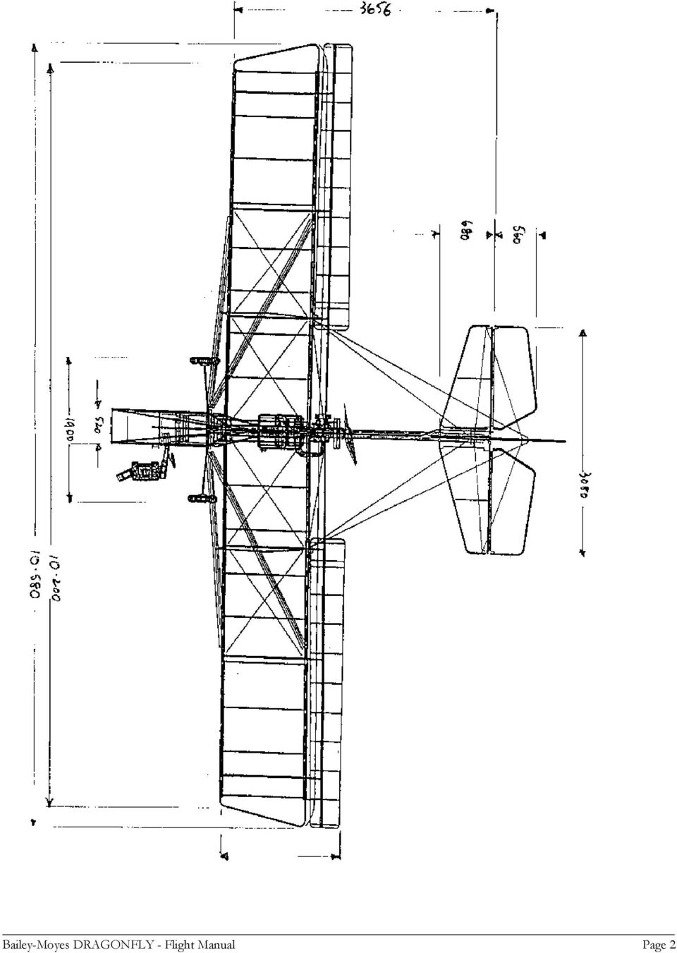
5 SPECIFICATIONS Wing Span m Leading Edge m Trailing Edge Mean Span m Wing Area m x 1.305m = m.sq Flapperon Area 8.2 m x.423m = m.sq Wing + Flapperon Area = m.sq MAC = = m Horizontal Stabilizer Span m Area m.sq Elevators m x.480 m =.610 m.sq Two Elevators.610 x 2 = m.sq Rudder Area 1.4 m x.700 m =.98 m.sq Weight with parachute Length 225 Kg m Bailey-Moyes DRAGONFLY - Flight Manual Page 3

6 INSPECTION STATUS LOGBOOK MAINTENANCE MANUAL The FAA recommend that the owner/pilot record in the Log Book all inspections and maintenance performed, together with performance information. This will create an AIRCRAFT MAINTENANCE HISTORY and will be invaluable in spotting trends. Bailey-Moyes DRAGONFLY - Flight Manual Page 4

7 1. ABBREVIATIONS AND GLOSSARY OF TERMS The following abbreviations are used in this flight manual. CG - MAC - DP - Rpm - Mph - Fpm - VFR - VNE - MTOW - G - Vs - Va - Center of Gravity. Denotes the static center of gravity. An imaginary point on the aircraft around which the aircraft is in equilibrium when static that is, the point where the weight forward and aft of the point balances each other if the aircraft was suspended from the CG. Mean aerodynamical chord. The mean chord of the wing including the lift producing ailerons. Datum point. The reference point for determining the position of the center of gravity and the maximum allowable range of this. Rotations per minute Miles per hour. Feet per minute. Visual Flight Rules Velocity Never Exceed Maximum Take Off Weight Acceleration due to Gravity Stall Speed or Minimum Steady Flight Speed Design Manouvering Speed. Bailey-Moyes DRAGONFLY - Flight Manual Page 5

8 PREFACE This light aircraft is manufactured to meet the requirements of several national categories. Australia accepts the Dragonfly as a Single Place Amateur Build Aircraft Registered as a 95/10 cat. or Experimental Two Place Aircraft. The F.A.A. in America accepts the Dragonfly as a Two Place Trainer Aircraft or an Experimental. The pilots weight range is from 60 kg to 100 kg and this aircraft when flown solo must only be flown from the front seat. The pilots weight is essential to be in the front seat to keep the aircraft balanced within its Center of Gravity Range. The pilot must have a valid Pilots License. Light aircraft must be flown and operated within the current local Airspace Regulations. The Dragonfly is designed to fly with the Flapperons in permanent Flaps on position. The low speed capabilities of this aircraft create a particular set of characteristics and each pilot should become familiar with its ground handling and flight characteristics before towing or carrying passengers. Light aircraft engines are not certified aircraft engines. This should always be considered when choosing a flight path. The path chosen should allow for emergency landings. Changes to the controls and control surfaces should not be attempted. There is a balance of aerodynamic forces to consider. Bailey-Moyes DRAGONFLY - Flight Manual Page 6

9 3. AIRCRAFT AND ENGINE DESCRIPTION 3.1 Aircraft Description The DRAGONFLY is a light, high wing, open cockpit monoplane The Airframe and fuselage is constructed of aluminium tube framework reinforced by struts and wire bracing. The wing, the stabilizer and the three axis control surfaces are covered by pre-manufactured dacron sails. The landing gear consists of two main wheels on chrome molly steel and axles, and a steerable tail wheel in a tail dragger configuration. The flexible steel axles work as shock absorbers during taxiing and landing. The tail wheel is steerable by mean of the rudder pedals. The main wheels are equipped with drumbrakes that are operated by means of the brake lever mounted on the throttle lever. 3.2 Engine Description. The engine is mounted, on rubber mounts, in a pusher configuration level with the wing and just behind the central part of the trailing edge. ENGINES The most popular engine chosen is the 582 Rotax Liquid Cooled two stroke motor and the weight and balance table is calculated with this engine. The Dragonfly can be fitted with a number of alternatives. When a lighter or heavier engine is fitted it is essential to maintain the CG range. This can be achieved by moving fixed items such as: 1: Radiator and Water 2: Battery 3: Parachute When moving one or more of these items careful consideration is necessary so that the operation of the item is not impaired. All chosen engines must operate in the pusher configuration. Dragonflys with intended tow use should use a reduction gearbox of 4 to 1 ratio and a 4 to 6 blade propeller. A large propulsion disc is necessary to achieve good towing results. Direct drive can be used with a suitable propeller. A longer take off run will be required and towing is not recommended. This configuration is useful only for cruising solo The 582 Rotax two stroke is mounted on a plate with its gearbox and radiator and muffler. This plate is mounted on 6 lord mounts to isolate vibration. The plate and engine can be removed and installed as a package. Bailey-Moyes DRAGONFLY - Flight Manual Page 7

10 OPERATOR PARAMETERS AND LIMITS 4 AIRSPEED:- The total load that may be carried by an ultralite aircraft will in some cases exceed the weight of the aircraft. The pilot in control must consider the airborne mass and the atmospheric conditions before executing maneuvers at a high speed. Maximum air speed at MTOW 56 mph Stall Speed at MTOW 28 mph Maximum air speed at MIN TOW 66 mph Stall Speed at MIN TOW 20 mph Weight Empty 225 kg. Maximum weight including pilot and passenger 450 kg Maximum load (See Sec. 8) Minimum load Pilot 60 kg SAFE OPERATIONS LOAD LIMITS Maximum positive dynamic load of aircraft 6 G Maximum negative dynamic load of aircraft 4 G Location of Center of Gravity C G in Flight Aircraft Attitude - Horizontal Stabilizer at 0 degrees Datum point - Nose or Fwd Cockpit Tube Maximum permissible FWD CG Location m AFT of DP Maximum permissible AFT CG Location m AFT of DP ENGINE SPEED: The permissible rpm limit will depend on the manufacturers recommendation (See Manual) for chosen engine. The 582 Rotax two cycle rpm limit is 6500 rpm Bailey-Moyes DRAGONFLY - Flight Manual Page 8

11 5 OPERATIONAL RESTRICTIONS This aircraft must not be used for aerobatic maneuvers. Maximum bank angle 60 degrees. Daylight flight between sunrise and sunset only and in VFR conditions. Flights into icing conditions should be avoided. Flights in turbulent conditions or when wind strength is in excess of 30 mph must be avoided. Bailey-Moyes DRAGONFLY - Flight Manual Page 9

12 AIRCRAFT HANDLING - OPERATION 6.1 OPERATING THE ENGINE WARNING: Hand starting by turning the propeller is dangerous. FUEL: See manufacturers advice on the engine you have installed STARTING THE ENGINE; 1. Pump fuel to the carburetors by operating the squeeze bulb in the fuel line till the bulb is firm. 2. Ensure that the throttle is in idle position 3. Choke on (Cold Start) 4. Check that prop is clear of bystanders. When you are ready call loud CLEAR PROP 5. Ensure that the front of the aircraft is clear. 6. Operate brakes. 7. Pump primer 3 times. 8 Ensure rear seat belt is fastened so that it will not fly into prop and no other item is loose that will be drawn into the propeller stream. PROP to warn observers. Turn Ign switch on and switch to start position clockwise. Call CLEAR Normally the engine will start within 2 seconds. Do not crank the engine more than 10 seconds if it does not start. Longer operation will overheat the starter motor. Cold conditions require more priming. Pump primer twice more and try again. The behavior of the engine will indicate the problem. In most cases it is too much or too little fuel to suit the temperature. Should the engine not start after three or four attempts then it is possible that the engine is flooded with fuel. To balance this situation, open the throttle to allow more air to be drawn in. Bailey-Moyes DRAGONFLY - Flight Manual Page 10

13 CAUTION: With the throttle open the aircraft will lurch forward when it starts. Operate the starter with one hand on the throttle to immediately pull the throttle back to idle if it starts. Operate the starter with the other hand and be ready to SWITCH OFF if an emergency arises. When the engine starts allow it to idle at 2000 rpm for a full minute to allow the engine to reach operating temperature. 6.2 TAXIING THE AIRCRAFT The Rudder pedals operate rudder and tail wheel steering. Control is easy and turning radius is average. Taxiing in cross wind up to 15 mph creates no problem. Both the rudder and tail wheel turn the aircraft in the same direction. left turn PUSH LEFT PEDAL For right turn PUSH RIGHT PEDAL As speed increases the tail wheel will leave the ground and the rudder will be responsible for steering. At times Low Speed Taxiing can be improved by pulling up elevator to hold the rear wheel firmly on the ground. When taxiing down wind keep the stick in Neutral Position. Taxiing cross wind lean the stick into the wind to reduce lift on the upwind flapperon. Failure to keep the aircraft balanced will lead to Ground Loops. Bailey-Moyes DRAGONFLY - Flight Manual Page 11

14 6.3 Takeoff and climb When the runway and the approach to the runway are clear taxi into starting position. Always take off into prevailing wind. conditions up to 15 mph. Takeoffs can be conducted in cross wind Go through the Start Check List (See Section 12.1) Release the brakes and when the aircraft starts to roll keep the stick slightly pulled back. At 20 mph the tailwheel will lift off. With the tailwheel 1ft off the ground keep accelerating while keeping the aircraft on a straight line with positive and firm rudder movements. At 30 mph the aircraft will lift off in the ground effect. Pull the stick back slightly and keep the aircraft in an even climb at a constant speed of 40 mph. At an altitude of 300 feet reduce the throttle and keep climbing at 40 mph. In very calm conditions and after extensive experience with the aircraft the climb can be performed with a single person onboard at 30 mph. At this speed the aircraft will climb best. Important During the climb it is imperative that the aircraft is not pulled into too steep an angle of attack, the aircraft will still be controllable but it will stop climbing. Inexperienced pilots can unwittingly bring the aircraft in such a situation especially when flying over obstacles. 6.4 Cross Country Flying A Compass and map are essential equipment for cross country flights. The Dragonfly has a range limit of 100 miles in nil wind conditions. Extra fuel should be carried if flying into wind. Remember that the Dragonflys specialty is low speed. The Dragonfly can land in all terrain for refueling, but flying into wind will necessitate regular fuel stops. A GPS is a useful tool when planning a cross country flight. When the country lacks landmarks a GPS and Compass will assist in setting a course. Bailey-Moyes DRAGONFLY - Flight Manual Page 12

15 6.5 Approach and Landing Always land into the prevailing wind when possible In idle the airspeed should always be kept at least at 35 mph. At half throttle the airspeed should always be kept at least at 40 mph Conduct a conventional approach to the runway with a downwind leg, a cross wind leg and a final approach while observing any special landing circuit rules that may be in force at the airfield. Always keep a good lookout for other aircraft during the landing Under normal conditions make the final approach with half throttle. Always make the final approach high with enough height to make the runway even with loss of the engine. When the aircraft is 3 feet above the ground pull the stick back slowly and bring the aircraft into level flight above the ground while using the throttle to keep the aircraft at constant altitude and a speed of 30 mph. Then ease the throttle back while pulling slowly back on the stick and bring the aircraft to the ground gently. The correct landing speed is 25 mph. When the aircraft touches down pull the throttle all the way back and bring the aircraft to a halt possibly by using the brakes. LANDING: When the Dragonfly is on the ground with all 3 wheels the wing has an angle of incidence of 13 degrees. This is sufficient angle of attack to lift the aircraft off the ground at flying speed. Therefore when you wish to land observe the old proverb "You don't land a plane, you fly it till it stops flying" Hold the plane off the ground till the tail wheel touches first. Then reduce throttle. Tail Draggers come to a halt quickly if landed in this fashion as the wing is at a high angle of incidence and creates maximum drag. Experience will allow you to land by greasing it in on all three wheels together or front wheels first. A hard landing front wheels first will lead to kangarooing, where the plane will take off again and again. This situation is best corrected by operating full throttle and take off again and make a fresh approach. Never overfly any obstacles on the final approach. Bailey-Moyes DRAGONFLY - Flight Manual Page 13

16 6.6 Dead Stick Flying If the engine is switched off while in the air let the engine cool at low throttle for a few minutes before switching the engine off. With the engine in idle turn the ignition switch to the "off" position. After a couple of revolutions the propeller will stand still. The optimum speed for gliding with the engine off is 35 mph. When landing with the engine off the approach must be steep with an airspeed of at least 45 mph. At 10 feet start easing back on the stick while closely monitoring the airspeed as the excess speed will be used up quickly when transferring to level flight. Restarting the engine in the air is easily achieved. Turn the ignition switch to on, move the throttle a bit forward of idle, then start the engine while keeping a constant airspeed. The engine will turn easier than on the ground, due to the wind passing the propeller. 6.7 Emergency Procedures Stall due to low airspeed. Push the stick fully forward until the aircraft has recovered flying speed, then ease back on the stick till normal flying position. Spin In all cases where low air speed has caused a stall or spin the aircraft will continue out of control until a flow of air is re-established over the wings. The immediate reaction must be STICK FORWARD. You must resist the temptation to pull the nose up. There is an old aviators saying FORWARDS TO FLY. BACK TO DIE. If the aircraft begins to spin the reaction must be STICK FORWARD and the opposite rudder. That means if you have entered a spin to the LEFT push hard on the right rudder pedal. Bailey-Moyes DRAGONFLY - Flight Manual Page 14

17 Failure of elevator The Horizontal Stabilizer is fixed at 13 degrees negative to the wing. Level flight can be maintained by increasing or decreasing air speed, with throttle use. Should pitch be uncontrollable after an elevator failure even after experimenting with the throttle, shut down the engine and operate the emergency parachute Failure of ailerons The Dragonfly's ailerons double as flaps and are in permanent flap position. Should one aileron fail take immediate steps to balance the aircraft with the other and final balance with the rudder. Should both fail and the aircraft is uncontrollable with the rudder then the pilot should operate the emergency parachute after shutting down the engine. Rudder failure Use the ailerons to steer the aircraft by banking to achieve direction. Land the aircraft immediately following any control surface failure or suspect operation Engine failure. If the engine fails at altitudes below 100 m above ground level do not attempt to restart the engine. Conduct the emergency landing as described in section 5.6. Land into the wind or uphill. Always monitor the airspeed closely. Do not turn close to the ground. Use a short flare. If the emergency landing has to be in trees flare above the treetops and let the aircraft fall into the tree from the minimum height and the lowest possible speed. If a treetop landing is unavoidable and if the altitude is sufficient (more than 100 m above ground) use the emergency parachute. Carburetor fire Should the carburetor or engine catch fire immediately push the throttle to full. Side slip the aircraft and carry out an emergency landing. Bailey-Moyes DRAGONFLY - Flight Manual Page 15

18 6.8 PROCEDURE ON FLOATS Flights on water can be pleasant when the water is smooth. Choose smooth conditions for your first float flights. Smooth water and nill wind usually go together so the take of run will be longer. TAKE OFF: Align the river or lake to allow sufficient take off space. Open the throttle to full throttle. The aircraft will be sluggish while the floats are fully wetted. Pull the stick back fully to give maximum lift till the floats climb onto the step. Ease the stick forward to allow the aircraft to reach full flying speed of 45 mph. Keep the aircraft skimming the water till you are satisfied that the speed will lift your passenger load and the floats. Then pull the nose up gently and leave the water. Climb gently and maintain airspeed till you have achieved an altitude of 100 meters then fly as normal. LANDING: On smooth water can be a surprise. The sky reflected on smooth water will lead you to believe that you are higher than you are. Don't look straight down. Keep your eyes ahead and keep the plane flying till it stops flying. Imagine you are landing tail first. STRONG WIND: Always take off into wind, but strong wind and big waves go together. Take off and landings into big waves are punishing to the aircraft and pilot. Strong Wind - Leaves rotors behind shore line trees and embankments. Don't be tempted by the smooth water along the shore to make your landings. Strong wind should be avoided till you are familiar with your territory and know how your aircraft behaves on floats. Bailey-Moyes DRAGONFLY - Flight Manual Page 16

19 7. MINIMAL EQUIPMENT LIST. One H-type seatbelt for each seat.. Airspeed indicator with O - 80 Mph range. Altimeter with Mb-correction scale.. Compass with deviation table.. Typeplate and loadsheet.. Start checklist. Emergency parachute system.. Tachometer.. Engine coolant temperature gauge.. Engine Hour Meter. Bailey-Moyes DRAGONFLY - Flight Manual Page 17

20 Bailey-Moyes DRAGONFLY - Flight Manual Page 18
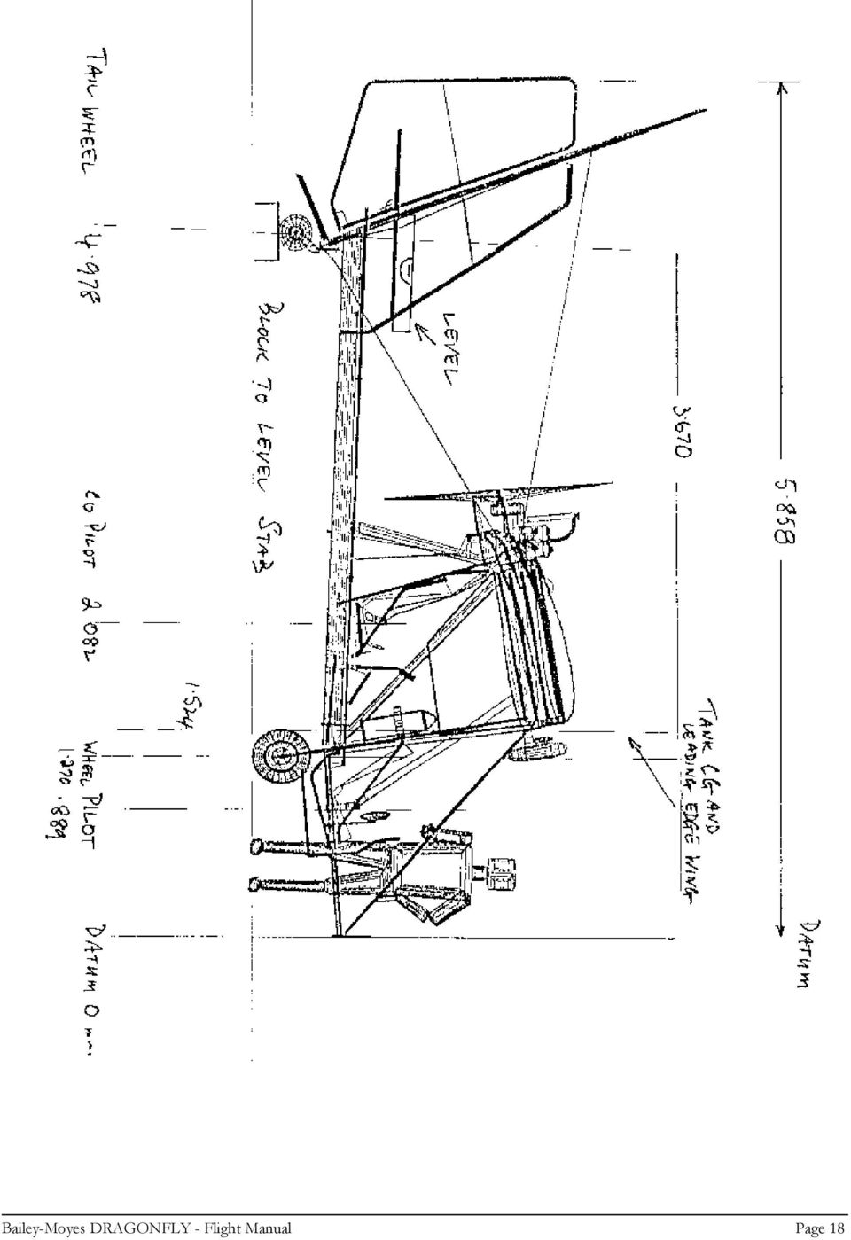
21 WEIGHT & LOAD SHEET CALCULATIONS 9.1 The weight and position of the center of gravity (CG) of the empty aircraft must be established to conduct load sheet calculations The aircraft must be weighed and measured in a fixed position and attitude and in windless conditions with wings level. Use a plumb line to project the following positions to the ground for measurements. The Datum is the point where all measurements will be taken and we have selected the nose or cockpit front. The attitude selected was to raise the tail wheel till the Horizontal Stabilizer was level by measurement with a level gauge (See sketch) The weights and measurements were recorded in this position and results as follows The Mean Aerodynamic Chord was calculated by adding the wing and flapperon area and divide by span. MAC = AREA = m.sq = m MEAN SPAN m 1. DATUM - Cockpit front or nose 0 2. Pilots Pelvis position - Pilot CG.889 m 3. Front Axle - Front Wheels m 4. Leading Edge of Wing m 5. Fuel Tank Center m 6. Rear Seat Pelvis position - Co Pilot CG m 7. Tail Wheel Axle m EMPTY WEIGHT WAS MEASURED AS FOLLOWS and the Moment Arm from DATUM used to calculate moments Empty Weight Mass Moment Arm Moments Front Rt. Wheel 77 kg m kg.m Front Left Wheel 79 kg m kg.m Rear Wheel 69 kg m kg.m Total Weight 225 kg Total Moments kg.m CG from Datum = Moment = kg = m Mass 225 kg The Leading Edge of the wing is m aft of Datum The empty weight CG position from the Leading Edge is then m m =.883 m As a percentage of MAC.883 = % Bailey-Moyes DRAGONFLY - Flight Manual Page 19
22 To calculate the maximum AFT position permissible a 60 kg pilot with 5 kg of fuel will give this result. ITEM WEIGHT ARM MOMENT RESULT Aircraft 225 kg m kg m Fuel 5 kg m 7.62 kg m Pilot 60 kg.889 m kg m 290 kg kg m m As a percentage of MAC =.533 =.553 = % MAC To calculate CG with Max take off weight MTOW with two 90 kg pilots Ad full fuel CG WITH MTOW - TWO 90 KG PILOTS Aircraft = 225 kg m kg m Fuel = 15 kg m kg m Pilot = 90 kg.889 m kg m Co Pilot = 90 kg m kg m 420 kg kg m CG = MOMENT = = M MASS 420 DATUM - CG - DATUM - WING M = =.456 =.278 = 27.8% MAC CG WITH MAX FUEL & 100 KG PILOT FOR MAX FORWARD CG Weight Arm Moment Aircraft 225 kg m kg m Fuel 15 kg m kg m Pilot 100 kg.889 m kg m 340 kg kg m CG from Datum = = M 340 Distance from Datum LE from Datum =.397 m CG =.397 =.242 m 24.2% MAC Bailey-Moyes DRAGONFLY - Flight Manual Page 20
23 9.1 CG POSITION REQUIREMENTS The CG must never be forward further than 1921 mm from Datum nor further back than 2077 mm from Datum The aircraft must never be flown solo from the back seat. The pilot minimum weight o 60 kg in the front seat is necessary to keep the aircraft in its CG range. The CG range as a percentage of the chord of the wing is from 33.7% with the lightest pilot to 24.2% with the heaviest pilot. 9.2 The Dragonfly used to obtain the CG information was fitted with a 582 liquid cooled Rotax engine and a 6 blade IVO Propeller The CG range is still valid if choice of engine is heavier or lighter. It is permissible to move fixed items into a new position to achieve the correct balance. The battery and parachute are two heavy items that can be mounted in new positions to achieve this result. When an item is remounted take care that its new position does not impede its operation. The empty weight CG should be m from Datum or 53.9% of the MAC. As stated in 9.2 this static empty weight balance can be achieved by remounting fixed items or adding ballast. Bailey-Moyes DRAGONFLY - Flight Manual Page 21
24 Aircraft Specific Weight and CG Position Dragonfly Serial No: Empty weight with standard equipment: Kg Empty weight fully equipped: Kg Type: Dragonfly - Weight at tail wheel (MR): Kg Weight at right main wheel: Kg Weight at left main wheel: Kg Total main wheel weight (MF): Kg x: mm y: mm z: mm z%: % of MCA Maximum takeoff weight: 450kg Maximum load: Kg Date: Inspector: 9.3 Load Sheet EMPTY WEIGHT CALCULATIONS Weight Momentarm Moment Result Kg Meters Kgm. Left Front Wheel Right front Wheel Rear Wheel Fuel Pilot CoPilot Bailey-Moyes DRAGONFLY - Flight Manual Page 22
25 10 TYPE PLATE DATA Airspeed Solo Dual Stall speed 20 mph 28 mph Maximum speed 65 mph 56 mph Wingloading Safe positive load Safe negative load 6 G 4 G Maximum operational windspeed Laminar windflow Turbulent conditions Crosswind takeoff 65 mph 56 mph 15 mph Aircraft load Maximum load See section 9.2 Minimum load 60 kg The use of the aircraft is the sole responsibility of the pilot Manufacturer Serial No. LTZ No. Build year Month Empty Weight Bailey-Moyes DRAGONFLY - Flight Manual Page 23
26 11. EMERGENCY PARACHUTE SYSTEM The manufacturers recommendations for mounting and maintaining the emergency parachute must always be adhered to. The parachute has its own operations manual that is supplied separately with this aircraft. It is especially important to protect the parachutes from moisture. If the parachute ever gets moist or wet it must be opened, dried and repacked. Parachutes with rocket deployment have a limited life span of the rockets. The parachute and rocket should be returned to BRS each 5 years for recharge and repack. There is a safety pin to prevent accidental deployment. This must be removed before each flight and replaced after each flight. Before each flight check that the parachute is securely mounted on the aircraft and that the bridle is securely attached to the main root tube. Bailey-Moyes DRAGONFLY - Flight Manual Page 24
27 12 AIRCRAFT PERFORMANCE The following stated aircraft performances are valid for the Dragonfly fitted with a 582 Rotax two stroke. Four to one Gearbox ratio with a 6 blade IVO (Ground adjustable) Propeller Takeoff Distance:- The stated values are valid at sea level in nil wind conditions and at temperature of 15 degrees C. The takeoff weights in the two cases were 340 kg solo and 430 kg two place on an even dry short grass runway. Higher temperature, weight or altitude will require additional runway. From a standing start the distance to take off:- Solo 65 m Two place 110 m Take off distance to clear 15 m high obstacle: Solo 150 m Two place 300 m Take off speed: Solo 30 mph Two place 40 mph Speed on clearing a 15 m obstacle:- Solo 35 mph Two place 45 mph 12.2 CLIMB RATE The stated values are for similar conditions as 12.1 and with engine operating at.6400 rpm. Best climb rate is achieved: ft/min ft/min Bailey-Moyes DRAGONFLY - Flight Manual Page 25
28 12.3 CRUISING SPEED & RANGE ON 20 LT FUEL Two stroke engines and the Dragonfly are inefficient at high speed. Cruise at 5000 rpm will give 45 mph Consumption at cruise is 8 lit per hour Range is approximately 100 miles PERFORMANCE WITH ENGINE OFF Minimum sink 35 mph Solo ft/min Dual ft/min Best glide angle Solo ft/min = 7 to one Dual ft/min = 7.5 to one The Dragonfly behaves much like a loaded truck rolling downhill. More weight gives a better glide angle. Bailey-Moyes DRAGONFLY - Flight Manual Page 26
29 13 AIRCRAFT ASSEMBLY Transport on trailer requires 1: Remove propeller - 6 mounting bolts 2: Disconnect throttle and carburetors Disconnect Fuel Line and primer Disconnect multi plug wiring 3: Disconnect starter cable Remove gap cover and wing straps 4: Remove engine by removing 6 bolts through Lord mounts 5: Disconnect rear wing to tail cables at tail and fuselage 6: Disconnect Aileron push rods and Aileron torque tube 7: Disconnect struts at bulkhead and jury struts. 8: Remove 4 wing mounting bolts and remove wings with struts attached to wings. Fold jury struts to main strut. Fold main struts to wings. 9. Mount wings on trailer. (See Sketch) 10. Disconnect horizontal stabilizer support cables by removing AN3 bolt at Stabilizer ends. Disconnect elevator connecting bracket. 11. Horizontal stabilizer and elevator will fold up to the vertical stabilizer and Rudder. Tie both the horizontal stabilizer tips together. 12. The fuselage and cockpit is easily handled and mounted on or in a trailer. For assembly Reverse the procedure. Two skilled people can assemble a Dragonfly in 20 minutes. Some of this procedure can be avoided by leaving the engine and propeller mounted if your trailer has sufficient space. The engine must be supported in the trailer when the wings and struts are removed. Bailey-Moyes DRAGONFLY - Flight Manual Page 27
30 Bailey-Moyes DRAGONFLY - Flight Manual Page 28
31 14 PREFLIGHT CHECKS Every day the plane is prepared for flight the entire aircraft must be subjected to a preflight check whereby the pilot visually checks the aircraft to ensure that the aircraft is in a state safe for flying. Sketch on next page:- Conduct the preflight check as a walk around the aircraft starting at the nose while checking the following parts of the aircraft; 1) Aircraft and engine controls. For each seat check that the rudder pedals and stick moves freely into all extreme positions. Check the links and connections on the stick and rudder to ensure that they are connected correctly and secured. Check the condition of the seats and check that the seatbelts are securely fastened. Check that the fuel tank is securely fastened and with the cap screwed tight and containing the sufficient amount of fuel for the intend flight time. 2) Instruments. Check that airspeed indicator works by blowing across the pitot tube, never blow directly into the tube as this can permanently damage the instrument. Ensure that the needle returns to zero position. Check the correct needle position of the other instruments. 3) Undercarriage and main wheels. Check (visually) that the tyres have the correct air pressure. Check that the tyres are free of any damage. Check that the wheel nuts are in place and that the chrome molly axles are securely fastened to the fuselage. 4) Emergency parachute. Check that the emergency parachute is securely fastened to the aircraft with the cover sitting in the correct position and with the bridle secured around the main root tube. Remove the safety pin from the release handle. Bailey-Moyes DRAGONFLY - Flight Manual Page 29
32 5) Inside and left part of the wing. Remove the inspection panel behind the parachute and inspect the inside of each side of the wing ensuring that all battens are in place and that all tubing is undamaged. Replace the inspection panel and secure using the velcro strips. Check that the dacron wing surface is free of holes or other damage. Check that each end of the strut is securely fastened on the fuselage and wing respectively. Check that the aileron is securely fastened to the wing and that it moves freely between the extreme positions. Check that the linkages and connections to the control surface are securely fastened. 6) Engine and propeller. Check that the propeller is free of damage, especially delamination of the composite material. Check that the engine and muffler is securely fastened to the engine assembly plate and that this is securely fastened to the aircraft. Ensure that all safety wires are in place as required on the propeller, gearbox and engine bolts. Check that the oil tank and the radiator are filled and check that the ignition cables are securely in place on the spark plugs. 7) Tail. Check that the rudder and elevator moves freely between the extreme positions. Check that the linkage and connections for the control surfaces are securely fastened. Check (visually) that the tail wheel tyre has the correct air pressure and is free of damage. Check that the wires from the rudder pedals are connected correctly to the steering plate. 8) Right part of the wing. As outside of the left wing. Bailey-Moyes DRAGONFLY - Flight Manual Page 30
33 14.1 Checklist Prior to Takeoff Immediately prior to takeoff the pilot must go through the following Start Checklists: 1) Seatbelts securely buckled 2) Free movement of rudder pedals and stick to the extreme positions. 3) Safety pin removed from parachute release. 4) Sufficient fuel in tank for the intended flying time 5) Choke ON 6) Electrical instruments ON 7) Adjust altimeter 8) Check wind direction. 9) Test engine response to throttle Bailey-Moyes DRAGONFLY - Flight Manual Page 31
34 15 AIRCRAFT MAINTENANCE AND SERVICE 1) Maintenance and service. All maintenance and service must be carried out by a skilled person. Any repairs or changes to the aircraft have to be reported and inspected. 2) Airworthiness inspection. In the case of an experimental aircraft it is the responsibility of the builder or by a person appointed by the local authority. 3) Airframe repair. Should be effected by the builder or appointed person using genuine or approved parts. Damaged parts should not be used for repair work. 4) Sail repair. Small tears in the sailcloth on the wing, stabilizers and control surfaces can be fixed by means of self adhesive cloth, this can be purchases from the manufacturer or most sail lofts. When cutting the patch always round the corners off. Larger tears and damage to stitching in the sail should always be repaired by a sailmaker. 5) Maintenance and cleaning. All metal parts are anodized to protect against corrosion and does not require any particular maintenance. The sail or airframe can be cleaned using water if grease or oil stains from the engine or exhaust has to be removed use warm water with a bit of dishwashing liquid. Do not use organic solvents to remove stains from the sailcloth. 6) Irregularities. Technical irregularities or other deficiencies of the aircraft must be reported to the manufacturer. 7) 25 hour check. For every 25 hours of airtime the following must be checked: The sparkplugs, the connections and linkages from the stick and rudder pedals to all control surfaces, if necessary oil or grease as required. Prop mounting bolt tension. 8) 50 hour check. For ever 50 hours of airtime the entire aircraft must be checked to the same extent as the preflight check (see section 13). Each of these checks should be documented with a completed checklist. The checklists should be filed chronologically. 9) Engine service and maintenance. For service and maintenance of the engine please refer to the Rotax engine manual provided separately with this aircraft. 300 hour engine check. For every 300 hours of airtime the engine must be serviced by the manufacturer or an approved mechanic. Bailey-Moyes DRAGONFLY - Flight Manual Page 32
35 16 DIMENSIONS AND ADJUSTMENT DATA Wingspan: m Wing area: m sq Wingchord: MAC m Dihedral of wing: 2.25 degrees The flapperons are mounted in a permanent flaps on position at an angle of 13 degrees posative to the wing. To accommodate all low speed requirements such as towing or flights on floats where low speed is essential. The flapperons can be raised to 10 degrees posative by repositioning the anchor bolt in the additional hole on the flap adjusting bracket. The horizontal stabilizer is set at 13 degrees negative angle to the wing to correct the pitching moment generated by the flapperons. The range of 10 degrees to 13 degrees on the flapperons will be balanced by the fixed setting on the horizontal stabilizer. Do not adjust the flapperons outside this range. Bailey-Moyes DRAGONFLY - Flight Manual Page 33
AIRCRAFT GENERAL www.theaviatornetwork.com GTM 1.1 2005 1-30-05 CONTENTS
 www.theaviatornetwork.com GTM 1.1 CONTENTS INTRODUCTION... 1.2 GENERAL AIRPLANE... 1.2 Fuselage... 1.2 Wing... 1.2 Tail... 1.2 PROPELLER TIP CLEARANCE... 1.2 LANDING GEAR STRUT EXTENSION (NORMAL)... 1.2
Multi Engine Oral Exam Questions
 Multi Engine Oral Exam Questions 1. What are the requirements for a multi-engine rating? 2. What is the max rated horse power at sea level? At 12,000 msl? 3. What is the rated engine speed? 4. What is
harbor cub Electric Remote Control Airplane Model 92906 assembly & Operating Instructions
 harbor cub Electric Remote Control Airplane Model 92906 assembly & Operating Instructions IMPORTANT: If damage is caused due to a crash, your warranty is void. Visit our website at: http://www.harborfreight.com
Assembly and Operating Manual Nano warbirds FW 190 Specification: *Length: 18 1/2"(470mm) *Wing Span: 21 7/10"(550mm)
 *Wing Span: 21 7/10(550mm)") Assembly and Operating Manual Nano warbirds FW 190 Specification: *Length: 18 1/2"(470mm) *Wing Span: 21 7/10"(550mm) *Flying Weight: 6 1/2 oz (185g) Dear customer, Congratulations on your choice of a
Assembly and Operating Manual Nano warbirds FW 190 Specification: *Length: 18 1/2"(470mm) *Wing Span: 21 7/10"(550mm) *Flying Weight: 6 1/2 oz (185g) Dear customer, Congratulations on your choice of a
File Number MDRA C20 MANUAL of PROCEDURES for INSPECTION of COMPOSITE AMATEUR-BUILT AIRCRAFT, INSPECTION AND TECHNICAL INFORMATION RECORD
 File Number MDRA C20 MANUAL of PROCEDURES for INSPECTION of COMPOSITE AMATEUR-BUILT AIRCRAFT, INSPECTION AND TECHNICAL INFORMATION RECORD GENERAL Section 1.4 FINAL INSPECTION 1. Have all re-inspection
Lancair Legacy Annual Condition Inspection Checklist
 Lancair Legacy Annual Condition Inspection Checklist Performed by: Completion Date: Complete Maintenance/Inspection Item Comments Pre-Inspection Research AD and Service bulletins Inspect entire airframe
FLYBLOCKTIME PA-28-140/160 Aircraft Type Checkout and Currency Quiz. NOTE: There may be one or more correct answers to each question.
 FLYBLOCKTIME PA-28-140/160 Aircraft Type Checkout and Currency Quiz Pilot s Name Date NOTE: There may be one or more correct answers to each question. 1 ) The engine in a PA-28-140/160 is a A. Continental
FLY SYNTHESIS STORCH HS-CL
 STORCH HS-CL MAINTENANCE MANUAL (ALID FOR ROTAX 912 UL AND JABIRU 2200 ENGINES) 00 28/05/07 New manual issue Num. Date Description Issued erify Approvation REISION The FlySynthesis s.r.l. it reserves him
MULTI-ENGINE TURBO-PROP AEROLANE ENDORSEMENT
 CAAP 5.23-1(1): Multi-engine Aeroplane Operations and Training 133 Appendix E to CAAP 5.23-1(1) MULTI-ENGINE TURBO-PROP AEROLANE ENDORSEMENT ENGINEERING, DATA AND PERFORMANCE QUESTIONNAIRE FOR (Aeroplane
MULTI-ENGINE PISTON AEROPLANE ENDORSEMENT ENGINEERING, DATA AND PERFORMANCE QUESTIONNAIRE
 CAAP 5.23-1(1): Multi-engine Aeroplane Operations and Training 117 APPENDIX D TO CAAP 5.23-1(1) MULTI-ENGINE PISTON AEROPLANE ENDORSEMENT ENGINEERING, DATA AND PERFORMANCE QUESTIONNAIRE FOR (Aeroplane
CIRRUS AIRPLANE MAINTENANCE MANUAL
 UNSCHEDULED MAINTENANCE CHECKS 1. DESCRIPTION The following describes those maintenance checks and inspections on the aircraft which are dictated by special or unusual conditions which are not related
MULTI-ENGINE TURBO-PROP AEROPLANE ENDORSEMENT
 MULTI-ENGINE TURBO-PROP AEROPLANE ENDORSEMENT ENGINEERING, DATA AND PERFORMANCE QUESTIONNAIRE FOR (Aeroplane make & model) Version 1 -August 1996 Name: ARN. Endorser: ARN: (Signature/Name) 1 The endorsement
Light Sport West Standard Flight Training Procedures for N110GX (Remos GX, 100 H.P.)
") Light Sport West Standard Flight Training Procedures for N110GX (Remos GX, 100 H.P.) Welcome to Light Sport West! Thank you for giving us the opportunity to provide all of your flight training needs. Our
Light Sport West Standard Flight Training Procedures for N110GX (Remos GX, 100 H.P.) Welcome to Light Sport West! Thank you for giving us the opportunity to provide all of your flight training needs. Our
Brief introduction----------------------------------------------------------------------------03
 A-1 skyraider Brief introduction----------------------------------------------------------------------------03 Specification----------------------------------------------------------------------------------03
STEADYfast Stabilizer Installation Notes Fifth Wheel and Travel Trailers 11/23/13
 STEADYfast Stabilizer Installation Notes Fifth Wheel and Travel Trailers 11/23/13 (See Supplemental Instructions for trailers with heavy duty round footplates and/or Power Leveling Systems) PHONE SUPPORT
MULTI-ENGINE PISTON AEROPLANE ENDORSEMENT
 MULTI-ENGINE PISTON AEROPLANE ENDORSEMENT ENGINEERING, DATA AND PERFORMANCE QUESTIONNAIRE FOR---------------------------------------------------------------------------------------------------------- (Aeroplane
Aviation Supplies & Academics, Inc. 7005 132nd Place SE Newcastle, Washington 98059-3153 www.asa2fly.com
 The Pilot s Manual 1: Flight School Aviation Supplies & Academics, Inc. 7005 132nd Place SE Newcastle, Washington 98059-3153 www.asa2fly.com Originally published by Aviation Theory Centre 1990 1993. Fourth
Cessna 172SP & NAV III Maneuvers Checklist
 Cessna 172SP & NAV III Maneuvers Checklist Introduction Power Settings This document is intended to introduce to you the standard method of performing maneuvers in Sunair Aviation s Cessna 172SP and NAV
SINGLE ENGINE TURBO-PROP AEROPLANE ENDORSEMENT
 SINGLE ENGINE TURBO-PROP AEROPLANE ENDORSEMENT ENGINEERING, DATA AND PERFORMANCE QUESTIONNAIRE FOR (Aeroplane make & model) Version 1-31 August 1996 Name: Endorser: (Signature/Name) Satisfactorily Completed
This file contains the full script of the corresponding video, published on YouTube. November 2014: http://youtu.be/wbu6x0hsnby
 This file contains the full script of the corresponding video, published on YouTube. November 2014: http://youtu.be/wbu6x0hsnby Background papers and links to formal FAA and EASA Aviation Regulations and
Chapter 2. Basic Airplane Anatomy. 2008 Delmar, Cengage Learning
 Chapter 2 Basic Airplane Anatomy Objectives Identify components of basic aircraft anatomy Understand aircraft size and weight categories List different types and examples of General aviation aircraft Military
TYPE CERTIFICATE DATA SHEET Nº EA-2011T03 Type Certificate Holder: COSTRUZIONI AERONAUTICHE TECNAM S.r.l. Via Tasso, 478 80127 - Napoli Italy
 TYPE CERTIFICATE DATA SHEET Nº EA-2011T03 Type Certificate Holder: COSTRUZIONI AERONAUTICHE TECNAM S.r.l. Via Tasso, 478 80127 - Napoli Italy EA-2011T03-02 Sheet 01 TECNAM P2006T 04 May 2012 This data
LAND LIKE A PRO. Jul 10, 2011 19 Comments by John Reid
 LAND LIKE A PRO Jul 10, 2011 19 Comments by John Reid We ve all heard the old adage, Takeoffs are optional; landings are mandatory. Bringing a plane back to the ground safely is a pilot s top goal. Unfortunately,
AIRCRAFT PERFORMANCE Pressure Altitude And Density Altitude
 Performance- Page 67 AIRCRAFT PERFORMANCE Pressure Altitude And Density Altitude Pressure altitude is indicated altitude corrected for nonstandard pressure. It is determined by setting 29.92 in the altimeter
FLIGHT TRAINING (AEROPLANE) BASED ON JAR FCL - PPL(A) FLIGHT INSTRUCTION Syllabus
 BASED ON JAR FCL - PPL(A) FLIGHT INSTRUCTION Syllabus") FLIGHT TRAINING (AEROPLANE) BASED ON JAR FCL - PPL(A) FLIGHT INSTRUCTION Syllabus for MARSPOLAR, DUBAI UAE Exercise 1 Familiarisation with the aeroplane characteristics of the aeroplane cockpit layout
FLIGHT TRAINING (AEROPLANE) BASED ON JAR FCL - PPL(A) FLIGHT INSTRUCTION Syllabus for MARSPOLAR, DUBAI UAE Exercise 1 Familiarisation with the aeroplane characteristics of the aeroplane cockpit layout
LANDING GEAR & BRAKES www.theaviatornetwork.com GTM 14.1 2005 1-30-05 CONTENTS INTRODUCTION... 14.2
 www.theaviatornetwork.com GTM 14.1 CONTENTS INTRODUCTION... 14.2 GENERAL... 14.2 MAIN LANDING GEAR... 14.2 Landing Gear Latch Lever and Handle... 14.2 Landing Gear Pressure Gauge... 14.2 Landing Gear Warning
TECHNICAL BULLETIN. Meritor WABCO Cab Leveling Valves and Chassis Leveling Valves. How the Cab Leveling and Chassis Leveling Valves Work
 Revised 02-00 TECHNICAL BULLETIN Meritor WABCO Cab Leveling Valves and Chassis Leveling Valves This technical bulletin covers both cab and chassis leveling valves manufactured by Meritor WABCO. While the
AutoGlow Installation and User s Manual. Installation and User s Manual. OSA AutoGlow. Figure 1. AutoGlow Introduction
 AutoGlow TM Installation and User s Manual Automatic Mode Velocity Sensing EEPROM OSA AutoGlow Thank you for purchasing the AutoGlow automatic glow plug control system. AutoGlow allows the model aviation
CHAPTER 10 PARKING AND STORAGE. Section Title Page
 CHAPTER 10 PARKING AND STORAGE Section Title Page 10-10 Parking.......................................... 10.1 10-11 Parking in High Wind or Turbulent Air............. 10.1 10-12 Main Rotor Blade Tie-Downs....................
Oral Preparation Questions
 Oral Preparation Questions The oral section of the practical test is the time when you need to demonstrate your understanding of the various tasks listed in the practical test standards and the factors
Sport Aviation Specialties
 Sport Aviation Specialties 2707 NW Cedar Brook, Lee s Summit, MO 64081, 816-838-6235, www.sportaviationspecialties.com WEIGHT & BALANCE FOR ELSA In certificating light-sport aircraft and conducting ELSA
Exam questions for obtaining aircraft licenses and ratings
 Exam questions for obtaining aircraft licenses and ratings Subject: PPL (A) Flight performance and planning Revision 1 07.10.2009. Period of validity: 01 January 2010 th - 31 December 2010 th Belgrade
INSPECTION BEFORE RIDING
 INSPECTION BEFORE RIDING Check the following items before riding. ITEM Engine cum transmission oil Fuel Tyres Battery Speedometer Lighting Steering Throttle Clutch Brakes Wheels WHAT TO CHECK FOR Availability
Micro. Pitts Special for the RFFS-100 by Chris O Riley
 Micro Pitts Special for the RFFS-100 by Chris O Riley F1 F2 F3 F4 1 2 3 4 All wood 1/32 inch sheet unless otherwise stated. F1 F2 F3 F4 Small balsa blocks for LG reinforcement Small balsa blocks for LG
TYPE CERTIFICATE DATA SHEET
 No Revision Aircraft Date VA502 7 SB7L-235 SB7L-360 SB7L-360A SB7L-360A2 5 May 2016 TYPE CERTIFICATE DATA SHEET This data sheet, which is part of Type Certificate No. VA502, Issue 4, lists the conditions
This section includes performance data on the King Air B200. Information consists of:
 King Air B200 POH Pilot's Operating Handbook: This section includes performance data on the King Air B200. Information consists of: 1. Critical Airspeeds 2. Operating NOTAMS 3. Fuel Loading Formula Checklists:
Pilot operating handbook. And. Flight operating supplement. AEROPRO + EuroFOX Aviation. EuroFOX
 ` AEROPRO, Production of UL Planes Dlha 126, 949 07 NITRA Slovakia www.aeropro.sk Pilot operating handbook And Flight operating supplement AEROPRO + EuroFOX Aviation EuroFOX The aircraft design has been
PRODUCT MANUAL SPECIFICATIONS SAFETY PRECAUTIONS. 1460mm/57.48in 1112mm/43.78in 27.74dm²/429.96in² 1600g/56.50oz 57.68g/dm²
 SPECIFICATIONS SAFETY PRECAUTIONS PRODUCT MANUAL Wing span: Length: Wing area: Flying weight: Wing loading: 1460mm/57.48in 1112mm/43.78in 27.74dm²/429.96in² 1600g/56.50oz 57.68g/dm² This electric R/C model
RC HELICOPTER INSTRUCTION MANUAL
 AGE 14+ RC HELICOPTER INSTRUCTION MANUAL 1. Smart R/C system 2. Full scale remote control 3. Omnidirectional flight 4. Smooth hover performance 5. Newly designed electricity saving functionality 6. Longer
1/5 PIPER J-3 CUB. Before commencing assembly,please read these instructions thoroughly. Wing Span:84. 0 in / 2130 mm
 INSTRUCTION MANUAL Before commencing assembly,please read these instructions thoroughly. 1/5 PIPER J-3 CUB 1/5 PIPER J-3 CUB Wing Span:8. 0 in / 130 mm Wing Area:968 sq in / 6. 5 sq dm Flying Weight:8.
APPENDIX 3-B Airplane Upset Recovery Briefing. Briefing. Figure 3-B.1
 APPENDIX 3-B Airplane Upset Recovery Briefing Industry Solutions for Large Swept-Wing Turbofan Airplanes Typically Seating More Than 100 Passengers Briefing Figure 3-B.1 Revision 1_August 2004 Airplane
INSTRUCTION MANUAL. Specification: collective pitch 3D quadcopter. TYPE: Collective Pitch Electric 3D Quadcopter. Rotor Diameter: 118MM.
 collective pitch 3D quadcopter INSTRUCTION MANUAL Specification: TYPE: Collective Pitch Electric 3D Quadcopter Rotor Diameter: 118MM Length:635 MM Width: 365 MM Weight: 986g w/out battery Flying weight
Airglas, Inc. MANUAL NO. GLH3000-105-AHSA. MODEL GLH3000 Ski Kit Actuated by Wipaire, Inc. Amphibious Float Hydraulic System
 Airglas, Inc. Amphibious hydraulic system addendum to Instructions for Continued Airworthiness Including Installation, Maintenance and Service Instructions MANUAL NO. GLH3000-105-AHSA MODEL GLH3000 Ski
Build and Fly the Fokker D- 8
 Details are carefully carried out. Note movable controls The high wing gives it unusual stability Build and Fly the Fokker D- 8 Complete Data From Which You Can Build a Successful Model of a Famous German
European Aviation Safety Agency
 TCDS No.: R.010 MBBBK117 Page 1 of 53 European Aviation Safety Agency EASA TYPECERTIFICATE DATA SHEET No. R.010 for MBBBK117 Type Certificate Holder AIRBUS HELICOPTERS DEUTSCHLAND GmbH Industriestrasse
EXCAVATOR SAFETY TRAINING
 EXCAVATOR SAFETY TRAINING INSPECTION CHECKLIST INSPECTION AREA INSPECTION RESULTS Sat. Unsat. N/A Comments Carrier & Car Body Rotation system Tracks Rollers Frame, welds, bolts Drive system Upper Structure
EME 35 Gasoline Engine User Manual
 EME 35 Gasoline Engine User Manual Eagle Master Engine EME 35 User Manual 1 SAFETY INSTRUCTIONS Thank you for purchasing EME 35 gasoline Engine. We at EME always strive to product reliable engines that
(AUS, NZL, UK, GER, RUS, SA, USA,
 Supermarine Aircraft Pty Ltd Supermarine Aircraft Kits Supermarine Aircraft has been in business for the last seventeen years selling our spitfire kits and in the last seven years Engines. We have sold
Range Road RR Series Semi-Automatic Firewood Processor. Crated Unit Assembly Manual
 Range Road RR Series Semi-Automatic Firewood Processor Crated Unit Assembly Manual 1 1) Undo 8-18mm x 19mm Nuts and bolts, 2 on each leg of top frame 2) Lift top of Metal crate off and move out of work
MODULE 11B. PISTON AEROPLANE AERODYNAMICS, STRUCTURES AND SYSTEMS
 MODULE 11B. PISTON AEROPLANE AERODYNAMICS, STRUCTURES AND SYSTEMS Note: The scope of this Module should reflect the technology of aeroplanes pertinent to the A2 and B1.2 subcategory. 11.1 Theory of Flight
The SeaRey - An Introduction
 The SeaRey - An Introduction Welcome to the beautiful Progressive Aerodyne SeaRey. The SeaRey is a very special aircraft. Created by a small team of engineers the SeaRey is perhaps the ultimate kit built
15GAL STEEL OIL DRAIN WITH 110V PUMP
 15GAL STEEL OIL DRAIN WITH 110V PUMP OWNER S MANUAL WARNING: Read carefully and understand all ASSEMBLY AND OPERATION INSTRUCTIONS before operating. Failure to follow the safety rules and other basic safety
ENGINE FIRE / SEVERE DAMAGE / SEPARATION ON TAKEOFF
 ENGINE FIRE / SEVERE DAMAGE / SEPARATION ON TAKEOFF According to RYANAIR Procedures PF PM REMARKS Control the aircraft (FULL T/O thrust can be manually selected) Announce «ENGINE FAILURE» or «ENGINE FIRE»
SINGLE ENGINE PISTON AEROPLANE ENDORSEMENT
 SINGLE ENGINE PISTON AEROPLANE ENDORSEMENT ENGINEERING, DATA AND PERFORMANCE QUESTIONNAIRE FOR (Aeroplane make and model) Version 1 August 1996 Name: Endorsed by: (Signature/Name) ARN: ARN Satisfactorily
Flightlab Ground School 5. Longitudinal Static Stability
 Flightlab Ground School 5. Longitudinal Static Stability Copyright Flight Emergency & Advanced Maneuvers Training, Inc. dba Flightlab, 2009. All rights reserved. For Training Purposes Only Longitudinal
SELF-STEERING AXLE TABLE OF CONTENTS
 SELF-STEERING AXLE TABLE OF CONTENTS Section 1 - Introduction Section 2 - Pre-Installation Check List Section 3 - Ride Height Adjustments Section 4 - Suspension Mount Section 5 - Axle Mount Section 6 -
Section A. GENERAL INFORMATION
 Section A. GENERAL INFORMATION I. Description The information and instructions for attaching the sidecar to the right-hand side of the motorcycle are contained in this handbook and must be carefully observed.
Maintenance manual DG-300 CLUB ELAN ACRO. Manual amendments. No. page Description Date Signature 1 1, 2, 21, diagram 4
 Manual amendments No. page Description Date Signature 1 1, 2, 21, diagram 4 Additional suspension of the waterbags ÄM 300/12/E/95 Nov. 95 2 1, 10 Landing gear control handle TN359/22 3 1, 2, 3, 8, 17a,
IMPORTANT INFORMATION - PLEASE READ. Table of Contents. Introduction. General Information
 IMPORTANT INFORMATION - PLEASE READ Introduction Congratulations! Welcome to the world of the ELLIPTICAL CROSS TRAINER. The ELLIPTICAL CROSS TRAINER is one of the finest and most comprehensive pieces of
Assembly Manual For. Dolphine Jet. Wingspan: 88 in Wingarea: 1479.8 sp in Length: 78.8 in Engine: 50CC. www.pilot-rc.com
 Assembly Manual For Dolphine Jet Wingspan: 88 in Wingarea: 1479.8 sp in Length: 78.8 in Engine: 50CC www.pilot-rc.com INTRODUCTION Thank you for purchasing our Dolphin Jet. we strive to achieve the real
Learning to Hover. Aircraft Technical Book Company http://www.actechbooks.com (800) 780-4115 (970) 887-2207
 780-4115 (970) 887-2207") 6 Learning to Hover I did most of the flying at that time and became very familiar with the helicopter's operation. During my years in aviation, I had never been in a machine that was as pleasant to fly
6 Learning to Hover I did most of the flying at that time and became very familiar with the helicopter's operation. During my years in aviation, I had never been in a machine that was as pleasant to fly
VFR Regulations Summary
 Gold Seal Online Ground School www.onlinegroundschool.com VFR Regulations Summary Pilot in Command The pilot in command is directly responsible for and the final authority as to the operation of the aircraft.
SUSPENSION AND STEERING OVERVIEW
 SUSPENSION SUSPENSION AND STEERING OVERVIEW The S40/V50 has a wide track and a long wheelbase for its relative size and weight. This gives the car stable and predictable driving characteristics. It also
Technical data. Assembly: Introduction. Before starting construction. Equipment needed. Glider or Electro Glider?
 Palio pro S2084 Technical data Wing span: Lenght: Weight: Wing area: Wing loading: El. Motor/ no. of cells: Controls: Introduction 2150 mm 1150 mm 1120 g 1860 g 42 dm2 27 g/dm2 44 g/dm2 600 / 7-8 cells
INSTRUCTION MANUAL. Black Angel. www.copterx.com. Features. Kit Helicopter. Copyright 2009 KY MODEL Company Limited.
 INSTRUCTION MANUAL Features - Carbon fiber main blade, tail blade, fly paddle, tail fin for extra weight saving and durability. - CNC machined high grade aluminum rotor head and tail gear box to ensure
COMPLETE KIT PARTS LIST
 Your kit contains the following parts. Please check your kit for any missing or damaged parts before starting construction. Wood Bag: COMPLETE KIT PARTS LIST 1 LC-504-01 3/32"x4"x24" Laser Cut Balsa Sheet
Vehicle Recovery and Towing
 Vehicle Recovery and Towing Guideline (Glove Box Edition) First Published 01-2010 Endsed by #1 Rule: It is always best to call a tow truck! However, if your company permits and equips you to pull out stuck
Specifications. *Specifications are subject to change without notice.*
 INSTRUCTION MANUAL Extra 300 EP (0) 50W Motor System Requires : -channel radio w/ mini servos, Outrunner Motor KM37810, w/ Propeller Adaptor HW3010, 0A Brushless ESC with 11x8E proepller, cells 1.8V 300mAh
European Aviation Safety Agency
 European Aviation Safety Agency EASA TYPE-CERTIFICATE DATA SHEET SZD-48 Jantar Standard 2 & Brawo Type Certificate Holder: Zakład Szybowcowy Jeżów Henryk Mynarski ul. Długa 93 58-521 Jeżów Sudecki EASA
Cessna Skyhawk II / 100. Performance Assessment
 Cessna Skyhawk II / 100 Performance Assessment Prepared by John McIver B.Eng.(Aero) Temporal Images 23rd January 2003 http://www.temporal.com.au Cessna Skyhawk II/100 (172) Performance Assessment 1. Introduction
2014 NIFA CRM Contestant Briefing Guide San Diego, California
 2014 NIFA CRM Contestant Briefing Guide San Diego, California Region 2 SAFECON 2014 November 12 15 This document supports the 2014 NIFA Collegiate Cockpit Resource Management Simulation and is not for
Class 5 to 7 Truck and Bus Hydraulic Brake System
 Class 5 to 7 Truck and Bus Hydraulic Brake System Diagnostic Guide 1st Edition * 5+0 Important Service tes The information in this publication was current at the time of printing. The information presented
Model 854/856. Operating and Assembly Manual. Palmor Products Inc. 5225 Serum Plant Road Thorntown, IN 46071
 Model 854/856 Operating and Assembly Manual Palmor Products Inc. 55 Serum Plant Road Thorntown, IN 46071 3/31/2015 SAFETY RULES Remember, any power equipment can cause injury if operated improperly or
Instruction Manual Specification:
 Instruction Manual Specification: Wingspan: 1855mm (73 ) Length: 1970mm (77.5 ) Weight: 7.5-9Kg (Approx.) Radio: 6+ Channel (Required) Turbine: 50-100N (5-10Kg) (Recommended) Introduction Congratulations
parts of an airplane Getting on an Airplane BOX Museum Aeronautics Research Mission Directorate in a Series
 National Aeronautics and Space Administration GRADES K-2 Aeronautics Research Mission Directorate Museum in a BOX Series www.nasa.gov parts of an airplane Getting on an Airplane MUSEUM IN A BOX Getting
Introduction to RC Airplanes. RC Airplane Types - Trainers, Sport RC Planes, 3D Acrobat RC Airplanes, Jets & More
 Introduction to RC Airplanes RC Airplane Types - Trainers, Sport RC Planes, 3D Acrobat RC Airplanes, Jets & More RC Airplane Types RC airplanes come in a few distinct categories. Each category generally
Assessment Specifications for Remotely Piloted Aircraft Systems, Class 1 AS-RPAS1
 AMC Civil Aviation Authority The Netherlands Assessment Specifications for Remotely Piloted Aircraft Systems, Class 1 AS-RPAS1 Version 1.1 1 December 2014-1 - CONTENTS (general layout) AS RPAS1 REMOTELY
CHAPTER 65 TAIL ROTOR DRIVE SYSTEM. Section Title Page
 CHAPTER 65 TAIL ROTOR DRIVE SYSTEM Section Title Page 65-00 Description........................................ 65.1 65-10 Tail Rotor Drive Fan Shaft.............................. 65.1 65-20 Tail Rotor
1000-LB. TRAILER JACK OWNER S MANUAL
 1000-LB. TRAILER JACK OWNER S MANUAL WARNING: Read carefully and understand all INSTRUCTIONS before operating. Failure to follow the safety rules and other basic safety precautions may result in serious
Oregon Fuel Injection
 Corporate Office: P.O. Box 21121, VE Pump Removal and Installation Cummins Lock Timed Applications Removal Clean the exterior of the injection pump and mounting surfaces. 1. Disconnect the fuel return
Volkswagen Jetta, Golf, GTI 1999, 2000 Brake System 47 Brakes - Hydraulic Components (Page GR-47)
") 47 Brakes - Hydraulic Components (Page GR-47) FS III front brake calipers, servicing Front brake caliper piston, removing and installing FN 3 front brake calipers, servicing Front caliper piston, removing
47 Brakes - Hydraulic Components (Page GR-47) FS III front brake calipers, servicing Front brake caliper piston, removing and installing FN 3 front brake calipers, servicing Front caliper piston, removing
European Aviation Safety Agency: Ottoplatz 1, D-50679 Cologne, Germany - easa.europa.eu
 EASA.A.527 Description: Language: TCDS: Product type: Manufacturer/TC Holder: A.527 AQUILA AT01 English EASA.A.527 Aircraft (CS-25, CS-22, CS-23, CS-VLA, CS-LSA) AQUILA Aviation GmbH European Aviation
Design Considerations for Water-Bottle Rockets. The next few pages are provided to help in the design of your water-bottle rocket.
 Acceleration= Force OVER Mass Design Considerations for Water-Bottle Rockets The next few pages are provided to help in the design of your water-bottle rocket. Newton s First Law: Objects at rest will
MEASURING WHEEL ALIGNMENT
 MEASURING WHEEL ALIGNMENT 2003-04 WHEEL ALIGNMENT Specifications & Procedures - Hummer - H2 Steering and vibration complaints are not always the result of improper alignment. One possible cause is wheel
European Aviation Safety Agency: Ottoplatz 1, D-50679 Cologne, Germany - easa.europa.eu
 EASA.A.412 Description: Language: TCDS: Product type: Manufacturer/TC Holder: A.412 Tecnam P92 English EASA.A.412 Aircraft (CS-25, CS-22, CS-23, CS-VLA, CS-LSA) TECNAM Costruzioni Aeronautiche European
Manual LOGO 400 SE. www.mikado-heli.de
 Manual www.mikado-heli.de LOGO 400 SE Mikado Model Helicopters GmbH Friedrich-Klausing-Straße 2 14469 Potsdam Germany Phone +49 (0)331 23749-0 Fax +49 (0)331 23749-11 www.mikado-heli.de Mikado Model Helicopters
B777. Landing Gear DO NOT USE FOR FLIGHT
 B777 Landing Gear DO NOT USE FOR FLIGHT Introduction The airplane has two main landing gear and a single nose gear. The nose gear is a conventional steerable two wheel unit. Each main gear has six wheels
SebArt professional line
 SebArt professional line New Sukhoi 29S 50E ARF ASSEMBLY MANUAL The new Sukhoi 29S 50E ARF was designed by Italy aerobatic pilot, Sebastiano Silvestri and the design is based on of his new Tournament Of
High Alpha 3D Maneuvers
 High Alpha 3D Maneuvers Harrier Pass Elevator Back Flip Parachute Whip Stalls Rolling Harrier 3D Rolling Turn 3D Knife Edge C-82 Rudder Warmup Note: Every flight mode and maneuver presented in this section
PUMP MAINTENANCE SCHEDULE AND CHECKLISTS
 PUMP MAINTENANCE SCHEDULE AND CHECKLISTS Providing a maintenance schedule defined specifically by run hours or yardage pumped serves only as a general guideline given the large amount of variables a unit
ZAPPY 3 OWNER S MANUAL. Read this manual completely before riding your Electric ZAPPY 3.
 ZAPPY 3 OWNER S MANUAL Read this manual completely before riding your Electric ZAPPY 3. TECHNICAL INFORMATION Model No. : ZAPPY 3 Product size Type of motor Motor power Battery type Battery Charger Charging
TOYOTA ELECTRONIC TRANSMISSION CHECKS & DIAGNOSIS
 Checks and Adjustments The transmission requires regular maintenance intervals if it is to continue to operate without failure. As we discussed in previous sections, transmission fluid loses certain properties
Certification Specifications for Large Rotorcraft CS-29
 European Aviation Safety Agency Certification Specifications for Large Rotorcraft CS-29 11 December 2012 CS-29 CONTENTS (general layout) CS 29 LARGE ROTORCRAFT BOOK 1 CERTIFICATION SPECIFICATIONS SUBPART
FXA 2008. UNIT G484 Module 2 4.2.3 Simple Harmonic Oscillations 11. frequency of the applied = natural frequency of the
 11 FORCED OSCILLATIONS AND RESONANCE POINTER INSTRUMENTS Analogue ammeter and voltmeters, have CRITICAL DAMPING so as to allow the needle pointer to reach its correct position on the scale after a single
OWNER S MANUAL Table Tennis Table Patent Pending
 OWNER S MANUAL Table Tennis Table Patent Pending Be sure to write your model number and serial number here for future reference. You can find these numbers printed on the bottom of the table. MODEL # T8179
LIFT-505. BMF Lift Kit. Yamaha Drive Gas or Electric. Installation Instructions
 LIFT-505 BMF Lift Kit Yamaha Drive Gas or Electric Installation Instructions Contents of LIFT-505 Yamaha Drive BMF Lift Kit: a (1 ea.) BMF A-Arm Assembly b (1 ea.) Driver Side Shock Tower c (1 ea.) Passenger
Owner s Manual Read and keep this manual. Patents World Wide
 Owner s Manual Read and keep this manual. Patents World Wide S & S Industries, Inc., Sarasota, FL, USA www.trail-gator.com Copyright 2008 All Rights Reserved The following manual is provided to assist
301.7D. Mini Hydraulic Excavator
 301.7D Mini Hydraulic Excavator Engine Weights Gross Power (ISO 14396) 17.9 kw 24.3 hp Operating Weight with Canopy 1610 kg 3,550 lb Net Power 13.2 kw 17.7 hp Operating Weight with Cab 1720 kg 3,792 lb
Super Stunts 60. Specifications. * Specifications are subject to change without notice.*
 A L M O S T- R E A D Y- T O - F LY INSTRUCTION MANUAL Super Stunts 60 0.60-0.75 cu. in. displacement 2-stroke Requires : 4- channel radio w / Specifications 5 standard servos Wing Span Wing Area Flying
FREEBIRD THE ORIGINAL D.I.Y. ORNITHOPTER! Tools and Glue. Required Materials
 Do not try to make your ornithopter using "household materials". If you want it to fly, you have to build it right. FREEBIRD THE ORIGINAL D.I.Y. ORNITHOPTER! Wingspan: 16 inches Weight: 1/4 ounce The Ornithopter