Manual LOGO 400 SE.
|
|
|
- Joleen Edwards
- 7 years ago
- Views:
Transcription
1 Manual LOGO 400 SE Mikado Model Helicopters GmbH Friedrich-Klausing-Straße Potsdam Germany Phone +49 (0) Fax +49 (0) Mikado Model Helicopters GmbH, V2.0
331 23749-0 Fax +49 (0)331 23749-11 www.")
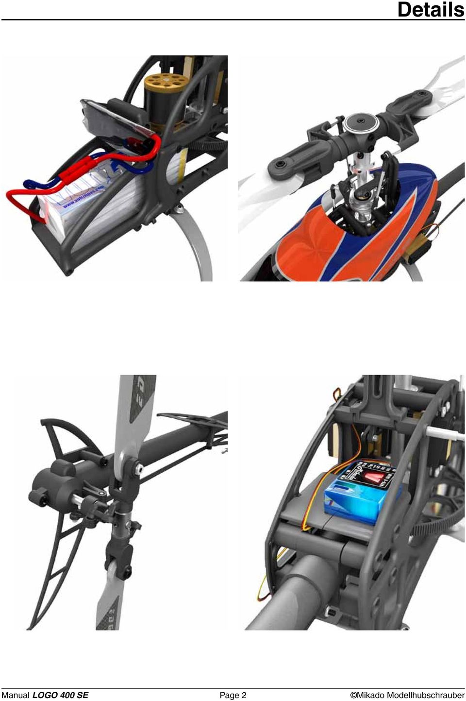
2 Details Manual LOGO 400 SE Page 2 Mikado Modellhubschrauber
3 Tools for Assembly & R/C Equipment Rubber Hammer Screwdrivers (plus and minus) Threadlock Grease Ball link pliers Ball link pliers Drill with 1.5mm bit (.059 in) Marker Hex Wrenches 1.5/2.0/2.5/3.0 mm (.055/.079/.098/.118 in) Scissors OPERATING YOUR MODEL SAFELY Pitch Gauge Operate the helicopter in spacious areas with no people nearby.!warning: Do NOT operate the helicopter in the following places and situations (or else you risk severe accidents): in places where children gather or people pass through in residential areas and parks indoors and in limited space in windy weather or when there is any rain, snow, fog or other precipitation If you do not observe these instructions you may be held reliable for personal injury or property damage! Always check the R/C system prior to operating your helicopter. When the R/C system batteries get weaker, the operational range of the R/C system decreases. Note that you may lose control of your model when operating it under such conditions. Keep in mind that other people around you might also be operating a R/C model. Never use a frequency which someone else is using at the same time. Radio signals will be mixed and you will lose control of your model. If the model shows irregular behavior, bring the model to a halt immediately. Turn off all power switches and disconnect the batteries. Investigate the reason and fix the problem. Do not operate the model again as long as the problem is not solved, as this may lead to further trouble and unforeseen accidents.! Warning: In order to prevent accidents and personal injury, be sure to observe the following: Before flying the helicopter, ensure that all screws are tightened. A single loose screw may cause a major accident. Replace all broken or defective parts with new ones, as damaged parts lead to crashes. Never approach a spinning rotor. Keep at least 10 meters/yards away from a spinning rotor blades. Do not Safety Instructions touch the motor immediately after use. It may be hot enough to cause burns. Perform all necessary maintenance. PRIOR TO ADJUSTING AND OPERATING YOUR MODEL, OBSERVE THE FOLLOWING! Warning: Operate the helicopter only outdoors and out of people s reach as the main rotor operates at high rpm!! Warning: While adjusting, stand at least 10 meters/yards away from the helicopter! Novice R/C helicopter pilots should always seek advice from experienced pilots to obtain hints with assembly and for pre-flight adjustments. Note that a badly assembled or insufficiently adjusted helicopter is a safety hazard! In the beginning, novice R/C helicopter pilots should always be assisted by an experienced pilot and never fly alone! Throttle channel should be in motor OFF position while powering up. When switching the R/C system ON or OFF, always proceed in the following order: When switching ON: Position the throttle control stick (on transmitter) to a position where the LOGO 10 motor does not operate. Turn on the transmitter. Turn on the receiver. Connect the motor battery. Operate your model. When switching OFF: Turn off the motor (move throttle control to a position where motor does not operate). Wait until the rotor head has stopped spinning. Disconnect the motor battery. Turn off receiver. Turn off transmitter. Manual LOGO 400 SE Page 3 Mikado Modellhubschrauber

4 4x M3x10 #1953 1x 1 Main Frame 1.1 Main Frame Bag 1 Bag mm #2371 #4170 #4187 #4188 Manual LOGO 400 SE Page 4 Mikado Modellhubschrauber

5 1 Main Frame 1.2 Bearing Case Bag 1 Bag 10 Bag 12 1x 10x19x5 # mm #2371 4x M3x10 #1953 #2380 M3x14 #1955 M3 Stopp #2074 Manual LOGO 400 SE Page 5 Mikado Modellhubschrauber

6 2 Landing Gear Bag 8 Bag 12 4x M3x12 #1954 4x M3 #2074 4x M3x3 #1920 Manual LOGO 400 SE Page 6 Mikado Modellhubschrauber

7 3 Motor Installation 3.1 Motor Attachment Bag 1 Bag 12 M3x12 #1954 3x9x1 #2011 When installing the motor, tighten the socket head cap screws only slightly, making sure that the motor can still be moved on the motor plate. Do not tighten the set screw fully until the final position of the pinion on the motor shaft is determined. This is done after installing the main gear. There are two options for attaching the pinion: 1. For securing the pinion, you may flatten the motor shaft where the set screw meets the motor shaft - without making a flat surface on the motor shaft. 2. Alternatively, you may screw the set screw directly onto the motor shaft. For this it is required that the set screw has an appropriate rim for engaging the motorshaft (all Mikado pinions have this rim). Note, however, that after attaching the set screw once, the rim becomes blunt and may not be used again. Manual LOGO 400 SE Page 7 Mikado Modellhubschrauber

8 4 Main Gear 4.1 Hub Bag 2 4x M3x8 #1915 #2731 #2725 4x 10x16x0.5 #2010 1x M,5x8 #1940 # x #1344 Manual LOGO 400 SE Page 8 Mikado Modellhubschrauber

9 4 Main Gear After having attached the freeway hub of the main gear to the rotor shaft, pull the rotor shaft slightly upward and simultaneously push the main shaft collar down onto ball bearing. Next tighten the set screws. The rotor shaft should turn easily and it should not have any axial play. too much backlash correct backlash too little backlash 4.2 Adjusting Gear Backlash The gear backlash must be adjusted (see drawings). Excess backlash can cause premature wear of the main gear and will lead to shorter flight times. Manual LOGO 400 SE Page 9 Mikado Modellhubschrauber
.")
10 5 Tail Rotor 5.1 Tail Rotor Shaft Bag 5 Bag 10 #2467 1x 10mm #2469 #2476 5x10x4 #2470 5x10x0.1 #2004 #2466 Should you have difficulty mounting the 10 mm pin, carefully tap it with a rubber hammer, or use a vice. The 5x10x4 bearings can also be mounted on the rotor shaft using a vice and tapping the shaft softly with a rubber hammer. If the tail rotor shaft shows axial play after closing the two halves of the tail rotor case, use one or two of the 5x10x0.1 washers which are included in the bag. #4150 #2189 # 4189 # 4181 Manual LOGO 400 SE Page 10 Mikado Modellhubschrauber

11 1x 5 Tail Rotor 5.2 Vertical Fin Bag 5 Bag 12 M3x25 #1958 M3x10 #1953 3x M3 #2074 #4182 Manual LOGO 400 SE Page 11 Mikado Modellhubschrauber

12 5 Tail Rotor 5.3 Pitch Slider Bag 5 Bag 10 #2455 6x10x2,5 #1440 #2452 It is important that the tail pitch plate #3030 is aligned properly on the control sleeve #2455. In the case of misalignment, the control sleeve may become deformed. The mounted tail pitch plate should be able to move on the tail rotor shaft with little resistance. 7mm #3030 Manual LOGO 400 SE Page 12 Mikado Modellhubschrauber

13 5 Tail Rotor 5.4 Tail Rotor Lever Bag 5 Bag 12 3x6x2,5 #2330 1x M3x14 #1955 1x M8 #1902 1x #1570 1x 3x5x5 #2448 1x 3x5x0,5 #2002 The mounted tail rotor lever should be able to move with little resistance. #2449 Manual LOGO 400 SE Page 13 Mikado Modellhubschrauber

14 5 Tail Rotor 5.5 Tail Rotor Hub Bag 5 Bag 10 M3x3 #3051 Large inner diameter M3x16 4x8x3 3x M2,5x6 #2462 2,5x6x0,5 Small inner diameter 5x8x0,5 4x8x2 M3 Stopp 4x8x3 4x8x2 4x8x3,5 M3x16 M2,5x6 2,5x6x0,5 Apply grease to bearing 1x M3 M3x3 5x8x0,5 Manual LOGO 400 SE Page 14 Mikado Modellhubschrauber

15 # Tail Boom 6.1 Tail Boom Holder Bag 6 Turn the tail drive belt 90 degrees (clockwise). Manual LOGO 400 SE Page 15 Mikado Modellhubschrauber
.")
16 6 Tail Boom 6.2 Tail Drive Pulley Bag 6 Bag 10 Bag 12 #2728 #2488 1x 4x13x5 #937 1x 4x9x4 #2489 4x8x1 #2013 1x 3x5 #1921 1x M3x18 #1965 1x M3 #2074! Important: Check belt tension prior to every flight. Incorrect belt tension can cause disturbances for your model R/C system. Incorrect belt tension can lead to a situation where you lose control of the tail rotor of your helicopter. For tightening the belt pull the tail boom holder toward the front. Belt tension is fixed with the M3x18 socket head cap screw for tightening the tail boom holder to the tail boom. The belt should be tight. When pressing with your fingers, both sides of the belt should not come in contact with each other. Manual LOGO 400 SE Page 16 Mikado Modellhubschrauber

17 6 Tail Boom 6.3 Tail Control Rod Bag 6 5 Min. Epoxy Screw the two 2 mm ball links onto the control rods. Their exact positions are of no importance at this point. The ball ends are attached to the balls more easily when the text on them is pointed away from the helicopter. #4179 1x M6 #1901 1x M2 #2070 M2,5x30#2770 Manual LOGO 400 SE Page 17 Mikado Modellhubschrauber

18 6 Tail Boom 6.4 Installation Bag 6 Bag 12 8x M3 x12 # ,5 mm # mm #2371 For mounting the tail assembly in the side-frames, pull the rear ends of the side-frames apart. For adjusting the gear backlash, insert a strip of paper between the main gear and the drive pulley, then press the drive pulley against the main gear. 6.5 Tail Rotor Blades Bag 5 #4184 M3x16 #1956 M3 #2074 Tighten the screws holding the tail rotor blades, but ensure that the blades move easily in the tail rotor holders under centrifugal force. #4184 Manual LOGO 400 SE Page 18 Mikado Modellhubschrauber

19 # min epoxy #4178 2,9x19 M3 #2074 4x 4,8 mm #1574 4x M2,5x30 # Tail Boom 6.6 Tail Boom Brace Bag 1 Bag 6 Bag 9 M3x20 #1957 3x5x2 #2463 The ball links should be screwed onto the control rod such that one is turned at 90 degrees with respect to the other. #4182 2,9x19 Manual LOGO 400 SE Page 19 Mikado Modellhubschrauber

20 7 Finished Main Frame & Tail Boom Manual LOGO 400 SE Page 20 Mikado Modellhubschrauber

21 8 Swashplate Bag 3 Tighten the pivot bolts very carefully. Do not overtighten them, as (7x) they will break off. 9 Servo Arms Bag 9 M8 #1902 M10 #1903 6x M2 #2070 4x 4,8 #1570 Rudder Servo Elevator Servo Aileron Servo Aileron Servo mm mm mm mm 120 CCPM Rudder Servo Elevator Servo Aileron Servo left Aileron Servo right Manual LOGO 400 SE Page 21 Mikado Modellhubschrauber
22 10 Servo Installation 10.1 Linkage Bag 9 # mm (.472 in) Linkage measurements for 3D pitch range (-12 to +12 ) 10.2 Tail Rotor Servo With LOGO 400 side-frames you can use two different sizes of tail rotor servos. A larger standard-size tail rotor servo can be mounted to the left side-frame, a smaller mini servo is mounted to right side-frame Elevator Servo Manual LOGO 400 SE Page 22 Mikado Modellhubschrauber
23 10 Servo Installation 10.4 Elevator Linkage/Swashplate 10.5 Canopy Fixing Bolts Bag 1 #2383 #2382 #2384 Manual LOGO 400 SE Page 23 Mikado Modellhubschrauber
24 10 Servo Installation 10.6 Aileron Servo left 10.7 Aileron Servo right Manual LOGO 400 SE Page 24 Mikado Modellhubschrauber
25 10 Servo Installation 10.8 Aileron Linkage Manual LOGO 400 SE Page 25 Mikado Modellhubschrauber
26 11 VBar Rotorhead Bag 7 M3x8 (5x) 5x M3x8 3x7 (5x) 8x11x4 2,5x7 3x7 2,5x7 8x11x4 8x11x1 4x 8x14x4 M3x10 8x11x1 6x14x5 Apply grease to bearing 10x14x1 8x14x4 1x M3x10 M3x20 M3x22 M4x12 Small inner diameter M3x24 Large inner diameter 4x11 3x 4x11 M3 Ø4,8x3 3x12 4x 3x7x3 10x14x1 M4x12 4x 3x6x2,5 3x5x2 M3x14 3x12 3x7x3 1x M3x5 3x5x0,3 M3x14 3x5x0,3 3x6x2,5 3x5x2 M3x5 Manual LOGO 400 SE Page 26 Mikado Modellhubschrauber
27 11 VBar Rotorhead 37 mm M3x20 M3 Stopp M3x22 Please adjust the swashplate driver in such a way that the balls on the inner and outer ring of the swashplate are positioned exactly on a line along the longitudinal axis of the heli. Manual LOGO 400 SE Page 27 Mikado Modellhubschrauber
28 12 Battery Support Bag 1 Bag 12 M3x40 M3x12 M2,5x10 1x M3x40 M3x12 #1954 1x M3x10 #1953 3x M2,5x10 #1938 3x M2,5 #2071 M3x12 M3x10 #4185 M2,5x10 Manual LOGO 400 SE Page 28 Mikado Modellhubschrauber
29 13 Overview 13.1 Chassis Manual LOGO 400 SE Page 29 Mikado Modellhubschrauber
30 13 Overview 13.2 Rotor Head Manual LOGO 400 SE Page 30 Mikado Modellhubschrauber
31 13 Overview 13.3 Tail Boom/Tail Rotor Manual LOGO 400 SE Page 31 Mikado Modellhubschrauber Construction & Rendering: Mehran Mahinpour Tirooni Layout & Realisation: CDT-Berlin
Manual LOGO 500 DX LOGO 500 3D LOGO 600 DX LOGO 600 3D. www.mikado-heli.de
 Manual LOGO 500 DX LOGO 500 3D LOGO 600 DX LOGO 600 3D www.mikado-heli.de Mikado Modellhubschrauber Friedrich-Klausing-Straße 2 14469 Potsdam Germany phone +49 (0)331 23749-0 fax +49 (0)331 23749-11 www.mikado-heli.de
INSTRUCTION MANUAL. Black Angel. www.copterx.com. Features. Kit Helicopter. Copyright 2009 KY MODEL Company Limited.
 INSTRUCTION MANUAL Features - Carbon fiber main blade, tail blade, fly paddle, tail fin for extra weight saving and durability. - CNC machined high grade aluminum rotor head and tail gear box to ensure
RC HELICOPTER INSTRUCTION MANUAL
 AGE 14+ RC HELICOPTER INSTRUCTION MANUAL 1. Smart R/C system 2. Full scale remote control 3. Omnidirectional flight 4. Smooth hover performance 5. Newly designed electricity saving functionality 6. Longer
VBAR NEO. Quick Start Guide Express-Firmware
 VBAR NEO Quick Start Guide Express-Firmware Welcome to VBar NEO! VBar NEO is an innovative product setting new standards for model helicopters in terms of flight performance and programming capacity. Features:
Tri-Homo Style Operation and Maintenance Instructions
 Tri-Homo Style Operation and Maintenance Instructions One Research Drive Stratford, CT 06615 (203) 375-0063 www.sonicmixing.com 1 Installation and Start-up Do not perform following adjustments without
1.8 CRANKSHAFT OIL SEALS
 SERIES 60 SERVICE MANUAL 1.8 CRANKSHAFT OIL SEALS An oil seal is fitted between each end of the crankshaft and the bores of the flywheel housing and gear case cover to retain the lubricating oil in the
INSTRUCTION MANUAL. Specification: collective pitch 3D quadcopter. TYPE: Collective Pitch Electric 3D Quadcopter. Rotor Diameter: 118MM.
 collective pitch 3D quadcopter INSTRUCTION MANUAL Specification: TYPE: Collective Pitch Electric 3D Quadcopter Rotor Diameter: 118MM Length:635 MM Width: 365 MM Weight: 986g w/out battery Flying weight
Brief introduction----------------------------------------------------------------------------03
 A-1 skyraider Brief introduction----------------------------------------------------------------------------03 Specification----------------------------------------------------------------------------------03
3. Loosen 3 x grub screws in the Dec end cap and unscrew the cap and counterweight shaft. NEQ6 Belt Modification Kit.
 NEQ6 Belt Modification Kit. Thank you for your purchase. Please read these instructions fully before fitting. Your package should contain 2 off 47 & 2 off 12 tooth aluminium pulleys 2 off belts 6mm wide
PRODUCT MANUAL SPECIFICATIONS SAFETY PRECAUTIONS. 1460mm/57.48in 1112mm/43.78in 27.74dm²/429.96in² 1600g/56.50oz 57.68g/dm²
 SPECIFICATIONS SAFETY PRECAUTIONS PRODUCT MANUAL Wing span: Length: Wing area: Flying weight: Wing loading: 1460mm/57.48in 1112mm/43.78in 27.74dm²/429.96in² 1600g/56.50oz 57.68g/dm² This electric R/C model
STEERING HANDLEBAR/FRONT WHEEL/ FRONT SHOCK ABSORBER
 14 14 STEERING HANDLEBAR/FRONT WHEEL/ SCHEMATIC DRAWING ------------------------------------------------- 14-1 SERVICE INFORMATION------------------------------------------------ 14-2 TROUBLESHOOTING-----------------------------------------------------
Rebuild Instructions for 70001 and 70010 Transmission
 Rebuild Instructions for 70001 and 70010 Transmission Brinn, Incorporated 1615 Tech Drive Bay City, MI 48706 Telephone 989.686.8920 Fax 989.686.6520 www.brinninc.com Notice Read all instructions before
TopSky DLG Installation Manual
 TopSky DLG Installation Manual Attention: Because after the compound materials solidify, there will be ammonia iris on the surface, which affect the bonding strength afterwards. Please polish with sandpaper
White Industries Rear Hub Instructions
 White Industries Rear Hub Instructions Tool required: 2mm allen/hex wrench, 19mm socket, 20mm socket, and mallet. 1. Loosen the set screws located in the adjusting collar by using a 2mm allen wrench inserted
Number Wheeler P/N Description Set Rex P/N Notes 1 603500 Base 1 J001 2 603501 Support, Right 1 J002 3 603502 Support, Left 1 J003 4 600328 Nut (M8)
") 1 603500 Base 1 J001 2 603501 Support, Right 1 J002 3 603502 Support, Left 1 J003 4 600328 Nut (M8) 4 5 600130 Spring Washer (8mm) 4 6 600344 Roll Pin (M6x30) 4 7 600129 Socket Hd Cap Screw (M8x25) 4 8
1 603500 Base 1 J001 2 603501 Support, Right 1 J002 3 603502 Support, Left 1 J003 4 600328 Nut (M8) 4 5 600130 Spring Washer (8mm) 4 6 600344 Roll Pin (M6x30) 4 7 600129 Socket Hd Cap Screw (M8x25) 4 8
300 SERIES 331, 332, 333, 344, 356 AND 367 MODELS
 Section: MOYNO 500 PUMPS Page: 1 of 8 Date: March 1, 1998 SERVICE MANUAL MOYNO 500 PUMPS 300 SERIES 331, 332, 333, 344, 356 AND 367 MODELS Mechanical Seal Models Packing Gland Models MODELS DESIGN FEATURES
SERVICE PARTS LIST PAGE 1 OF 6 BASE ASSEMBLY SPECIFY CATALOG NO. AND SERIAL NO. WHEN ORDERING PARTS 12" DUAL BEVEL COMPOUND MITER SAW B27A
 PAGE 1 OF 6 BASE ASSEMBLY 00 0 EXAMPLE: Component Parts (Small #) Are Included When Ordering The Assembly (Large #). SPECIFY CATALOG NO. AND NO. WHEN ORDERING PARTS 1 02-80-0050 Thrust Bearing (1) 2 05-80-0510
Technical data. Assembly: Introduction. Before starting construction. Equipment needed. Glider or Electro Glider?
 Palio pro S2084 Technical data Wing span: Lenght: Weight: Wing area: Wing loading: El. Motor/ no. of cells: Controls: Introduction 2150 mm 1150 mm 1120 g 1860 g 42 dm2 27 g/dm2 44 g/dm2 600 / 7-8 cells
Assembly and Operating Manual Nano warbirds FW 190 Specification: *Length: 18 1/2"(470mm) *Wing Span: 21 7/10"(550mm)
 *Wing Span: 21 7/10(550mm)") Assembly and Operating Manual Nano warbirds FW 190 Specification: *Length: 18 1/2"(470mm) *Wing Span: 21 7/10"(550mm) *Flying Weight: 6 1/2 oz (185g) Dear customer, Congratulations on your choice of a
Assembly and Operating Manual Nano warbirds FW 190 Specification: *Length: 18 1/2"(470mm) *Wing Span: 21 7/10"(550mm) *Flying Weight: 6 1/2 oz (185g) Dear customer, Congratulations on your choice of a
Build Tips for Sakura Zero S
 Build Tips for Sakura Zero S Revision Control Revision Revision Notes Report By Reviewed By Rev0 First Draft Marc Baynham Introduction The way in which a competition electric radio controlled car such
ZAPPY 3 OWNER S MANUAL. Read this manual completely before riding your Electric ZAPPY 3.
 ZAPPY 3 OWNER S MANUAL Read this manual completely before riding your Electric ZAPPY 3. TECHNICAL INFORMATION Model No. : ZAPPY 3 Product size Type of motor Motor power Battery type Battery Charger Charging
Slide the new steering column shaft through the steering column from the driver compartment.
 Slide the new steering column shaft through the steering column from the driver compartment. Push the column shaft through the steering column until the machined end is out past the column lower bushing.
SLACK PERFORMANCE KARTS
 SLACK PERFORMANCE KARTS SET UP GUIDE Thank you for purchasing a 2013 Slack Axiom Chassis. Performance Mfg. strives to provide you with the very best chassis and components on the market today. Your satisfaction
Assembly and Usage Instructions
 Assembly and Usage Instructions A Product 5885 West Van Horn Tavern Road Columbia, MO 65203 www.caldwellshooting.com Instruction #1001667 Limited Warranty Every Caldwell product is warrantied to be free
CAM-03, Camshaft Assembly Oil Seal Replacement
 CAM-03, Camshaft Assembly Oil Seal Replacement Tools Jack stands Floor Jack Metric Socket set Metric Wrench set Porsche Timing Belt Tension tool (P9201) Flywheel Lock (P9206) Balance Shaft Pin Spanner
46431x92A Garden Tractor (1998) Page 1 of 16 Body Chassis
 Page 1 of 16 Body Chassis") 46431x92A Garden Tractor (1998) Page 1 of 16 Body Chassis 46431x92A Garden Tractor (1998) Page 2 of 16 Body Chassis 1 092546E701 Bracket, Seat 2 091963 Z Plate Assembly, Switch 3 164X26 Spring, Compression
46431x92A Garden Tractor (1998) Page 1 of 16 Body Chassis 46431x92A Garden Tractor (1998) Page 2 of 16 Body Chassis 1 092546E701 Bracket, Seat 2 091963 Z Plate Assembly, Switch 3 164X26 Spring, Compression
COOPER S PULLEY UPGRADE KIT INSTALLATION INSTRUCTIONS PART NUMBER NME5011
 COOPER S PULLEY UPGRADE KIT INSTALLATION INSTRUCTIONS PART NUMBER NME5011 Below are instructions for the Mini Mania Pulley Upgrade Kit, Part Number NME5011. Please take all necessary precautions for working
HYDRAULIC LIFT TABLE CART 2200-LB.
 HYDRAULIC LIFT TABLE CART 2200-LB. OWNER S MANUAL WARNING: Read carefully and understand all MACHINE ADJUSTMENT AND OPERATION INSTRUCTIONS before operating. Failure to follow the safety rules and other
Have fun, nevertheless!
 Nanomum The Nanomum is a small pusher gyro for flying indoors or outdoors in very calm weather. It's got a dc head and is easy to build and easy to fly - I hope. Specs: AUW 70 g / 2.5 oz. Rotor diameter:
HOME GYM. Model. Retain This Manual for Reference OWNER'S MANUAL. www.hyper-extension.com
 NOTE: Please read all instructions carefully before using this product Table of Contents Safety Notice www.hyper-extension.com HOME GYM 50036 Hardware Identifier Assembly Instruction Parts List Warranty
SPRITE and BIGFOOT DESKTOP CNC MACHINE KIT ASSEMBLY INSTRUCTIONS
 SPRITE and BIGFOOT DESKTOP CNC MACHINE KIT ASSEMBLY INSTRUCTIONS README FIRST: Thank you for purchasing your MyDIYCNC Desktop CNC Machine Kit. We hope this versatile and innovative machine brings you many
Cable Drum Installation
 20 Cable Drum Installation COUNTERBALANCE None Shake the TorqueMaster spring tube gently to extend the winding shafts out about 5" on each side. For single spring applications, there will be no left hand
harbor cub Electric Remote Control Airplane Model 92906 assembly & Operating Instructions
 harbor cub Electric Remote Control Airplane Model 92906 assembly & Operating Instructions IMPORTANT: If damage is caused due to a crash, your warranty is void. Visit our website at: http://www.harborfreight.com
HT-0095 Mini PV Receptacles 22-32 AWG Crimping Hand Tool. Tool P/N HT-0095
 HT-0095 Mini PV Receptacles 22-32 AWG Crimping Hand Tool Tool P/N HT-0095 FCI MANUAL P/N 415988-001 Issued: Date (03/12/99) Page 1 of 18 HT-0095 Issued: Date (03/12/99) Page 2 of 18 Introduction Table
Operating Instructions Parts List Manual Scissor Lift Pallet Truck
 Operating Instructions Parts List Manual Scissor Lift Pallet Truck Note: Operator MUST read and understand this operating instructions before use this Hand Scissor Lift. Thank you for using this hand scissors
Triple Threat 3-in-1 Game Table 3 IN 1 GAME TABLE
 NG0M Triple Threat 3-in- Game Table 3 IN GAME TABLE Thank 3 in Y Game Table Thank you for your purchase of our product. We work around the clock and around the globe to ensure that our products maintain
OWNER S MANUAL Table Tennis Table Patent Pending
 OWNER S MANUAL Table Tennis Table Patent Pending Be sure to write your model number and serial number here for future reference. You can find these numbers printed on the bottom of the table. MODEL # T8179
Range Road RR Series Semi-Automatic Firewood Processor. Crated Unit Assembly Manual
 Range Road RR Series Semi-Automatic Firewood Processor Crated Unit Assembly Manual 1 1) Undo 8-18mm x 19mm Nuts and bolts, 2 on each leg of top frame 2) Lift top of Metal crate off and move out of work
Front brakes (FN- 3), servicing
, servicing") j a t Front brakes (FN- 3), servicing 46-1 Front brakes, servicing Note: Install complete repair kit. After replacing brake pads and before moving vehicle, depress brake pedal several times firmly to properly
j a t Front brakes (FN- 3), servicing 46-1 Front brakes, servicing Note: Install complete repair kit. After replacing brake pads and before moving vehicle, depress brake pedal several times firmly to properly
13. REAR WHEEL/BRAKE/SUSPENSION
 13. REAR WHEEL/BRAKE/SUSPENSION 13 3.5~4.5kg-m 8.0~10.0kg-m 0.8~1.2kg-m 3.0~4.0kg-m 2.4~3.0kg-m 3.5~4.5kg-m 6.0~8.0kg-m 13-0 13. REAR WHEEL/BRAKE/SUSPENSION 13 REAR WHEEL/BRAKE/SUSPENSION SERVICE INFORMATION...
Drive shaft, servicing
 Volkswagen Passat B6 - Drive shaft, servicing Стр. 1 из 41 40-7 Drive shaft, servicing Drive shafts, overview I - Assembly overview: Drive axle with CV joint VL100 40-7, Drive axle with CV joint VL100,
LU6X-130 Instructions and Parts List (including LU6X Basic) Operating Instructions
 Operating Instructions") LORTONE LU6X-130 Item # 061-092 LU6X Basic Item # 061-090 LU6X-130 Instructions and Parts List (including LU6X Basic) Operating Instructions Introduction The LU6X is one the most versatile pieces of equipment
LORTONE LU6X-130 Item # 061-092 LU6X Basic Item # 061-090 LU6X-130 Instructions and Parts List (including LU6X Basic) Operating Instructions Introduction The LU6X is one the most versatile pieces of equipment
Introduction to RC Airplanes. RC Airplane Types - Trainers, Sport RC Planes, 3D Acrobat RC Airplanes, Jets & More
 Introduction to RC Airplanes RC Airplane Types - Trainers, Sport RC Planes, 3D Acrobat RC Airplanes, Jets & More RC Airplane Types RC airplanes come in a few distinct categories. Each category generally
FRONT BUMPER INSTALLATION INSTRUCTIONS 2007-2011 DODGE / MERCEDES SPRINTER
 Aluminess Products Inc 9402 Wheatlands Ct. #A Santee, CA 92071 619-449-9930 FRONT BUMPER INSTALLATION INSTRUCTIONS 2007-2011 DODGE / MERCEDES SPRINTER Please read before beginning Stainless steel hardware
Owner s Manual Read and keep this manual. Patents World Wide
 Owner s Manual Read and keep this manual. Patents World Wide S & S Industries, Inc., Sarasota, FL, USA www.trail-gator.com Copyright 2008 All Rights Reserved The following manual is provided to assist
AstroSystems Digital Setting Circles for Zhumell, GSO, Apertura and Astro-Tech
 AstroSystems Digital Setting Circles for Zhumell, GSO, Apertura and Astro-Tech Components 1 Sky Commander Digital Setting Circle Computer 2 Encoders 10,000 step 1 Sky Commander Digital Setting Circle Manual
ANGEL. Remote control helicopter. Operating manual
 ANGEL Remote control helicopter Operating manual R CATALOG SPECIFICATIONS 02 CAUTION 03 TIPS FOR SAFETY 03 CHARGE MODE AND WARNING 05 SAFETY INSTRUCTIONS FOR LI-POLY BATTERIES 06 PARTS LIST 07 OPERATION
Front axle components, overview
 just a test. Front axle components, overview 40-1 General Information Load bearing components and parts of the suspension must not be welded or straightened. Vehicles without drive axle must not be moved,
RETRACTABLE LANDING GEAR
 HUGHES H-1 RETRACTABLE LANDING GEAR INSTALLATION INSTRUCTIONS Congratulations on your decision to add retractable landing gear to your RC model of the Hughes H-1. Though originally conceived simply for
12. REAR WHEEL/BRAKE/SUSPENSION
 12 12 12-0 SERVICE INFORMATION... 12-1 REAR BRAKE... 12-5 TROUBLESHOOTING... 12-2 REAR SHOCK ABSORBER... 12-8 REAR WHEEL... 12-3 REAR FORK... 12-9 SERVICE INFORMATION GENERAL INSTRUCTIONS When installing
STEADYfast Stabilizer Installation Notes Fifth Wheel and Travel Trailers 11/23/13
 STEADYfast Stabilizer Installation Notes Fifth Wheel and Travel Trailers 11/23/13 (See Supplemental Instructions for trailers with heavy duty round footplates and/or Power Leveling Systems) PHONE SUPPORT
Volkswagen Jetta, Golf, GTI 1999, 2000 Brake System 46 Brakes - Mechanical Components (Page GR-46)
") 46 Brakes - Mechanical Components (Page GR-46) Front brakes Brake pads, removing and installing Brake pads, removing and installing FN 3 brake caliper, servicing FS III brake caliper, servicing Rear wheel
46 Brakes - Mechanical Components (Page GR-46) Front brakes Brake pads, removing and installing Brake pads, removing and installing FN 3 brake caliper, servicing FS III brake caliper, servicing Rear wheel
DYNA RIDER FOOTBOARD KIT
 -J0 REV. 0-0-0 DYNA RIDER FOOTBOARD KIT GENERAL Kit Number 000 Models For model fitment information, see the P&A Retail Catalog or the Parts and Accessories section of www.harley-davidson.com (English
GTI VR6 Front Wheel Bearing DIY http://www.gtishrine.com
 GTI VR6 Front Wheel Bearing DIY http://www.gtishrine.com This procedure covers replacing the front wheel bearings. Tools and Parts required: Wheel Bearing Puller w/ ABS adapter. Available for rent from
Dismantling and Reassembly Guide
 Super X3 Mill Dismantling and Reassembly Guide A picture story book to help you dismantle and reassemble your Sieg Super X3 Mill Arc Euro Trade Ltd. 10 Archdale Street, Syston, Leicester, LE7 1NA. Web:
Post Mount Light Installation*
 Post Mount Light Installation* *For the general installation of most Post Mount Spotlights, many vehicles may need slight modifications to these instructions. You will need the following tools: High torque
1/29/2008 DR70. Baja Motorsports Inc. P.O. Box 61150 Phoenix, AZ 85082 Toll Free: 888-863-2252 PART NUMBERS PRICES ARE SUBJECT TO CHANGE 1 of 43
 DR70 Toll Free: 888-863-2252 PART NUMBERS PRICES ARE SUBJECT TO CHANGE 1 of 43 CYLINDER & CYLINDER HEAD 1 DR70-001 883099044472 CYLINDER 1 1 2 DR70-002 883099044489 GASKET, CYLINDER 1 1 3 DR70-003 883099044496
Number Wheeler P/N Description Set Rex P/N Notes
 1 604041 Base 1 4041 2 604042 Base Cover 1 4042 3 608849 Washer (M5) 2 4 600124 Spring Washer (M5) 2 5 600329 Rd Hd Machine Screw (M5x8) 2 6 604047 Strainer 1 4047 7 600204 Rd Hd Machine Screw (M6x10)
1/5 PIPER J-3 CUB. Before commencing assembly,please read these instructions thoroughly. Wing Span:84. 0 in / 2130 mm
 INSTRUCTION MANUAL Before commencing assembly,please read these instructions thoroughly. 1/5 PIPER J-3 CUB 1/5 PIPER J-3 CUB Wing Span:8. 0 in / 130 mm Wing Area:968 sq in / 6. 5 sq dm Flying Weight:8.
Auto-belay Cable Replacement Process
 Auto-belay Cable Replacement Process Version 2.00 WARNING: The air pressure in the auto-belay system is what causes the cable to be retracted when releasing the cable or climbing the wall with the cable
Original Assembly Guide
 TCT Multipurpose Single Bevel Sliding Compound Mitre Saw Original Assembly Guide Read instructions before assembling this tool. Table of Contents GB Assembly Guide Read instructions before assembling this
Pallet Jack. OWNER S MANUAL Model MH1230. Important Safety Instructions Assembly Instructions Parts and Hardware Identification
 OWNER S MANUAL Model MH1230 Important Safety Instructions Assembly Instructions Parts and Hardware Identification Pallet Jack CAUTION: Read, understand and follow ALL instructions before using this product
Tool And Material Checklist
 HOW - TO CV JOINTS CV JOINTS Tool And Material Checklist Screwdriver Metal Shears Breaker Bar or Torque Wrench Assorted Wrenches Wire Evaporating Spray Solvent Pusher Tool Vise Snap Ring or Duckbill Pliers
Instructions and precautions. Fork Height. Visit our website at: http://www.harborfreight.com
 Pallet Jack Item 68760 / 68761 Instructions and precautions Specifications Capacity Control Lever Fork Height Fork Length Fork Width Maximum Minimum Width over Forks Steering Wheel Dia. 2-1/2 Ton (5,000
BR150 Pmi Baja Reaction 150cc Go Kart (VIN PREFIX L4VM)
") Page 1 of 21 Product Information Baja Web > Product Information > Parts Lists > GOKART > BR150 Pmi Baja Reaction 150cc Go Kart (VIN PREFIX L4VM) BR150 Pmi Baja Reaction 150cc Go Kart (VIN PREFIX L4VM)
Page 1 of 21 Product Information Baja Web > Product Information > Parts Lists > GOKART > BR150 Pmi Baja Reaction 150cc Go Kart (VIN PREFIX L4VM) BR150 Pmi Baja Reaction 150cc Go Kart (VIN PREFIX L4VM)
Wiper Motor Marinco 2.5. Installation Instructions
 Wiper Motor Marinco 2.5 Installation Instructions Wiper Motor Marinco-2.5 The Marinco 2.5 Wiper Motor Offers the Following Features: Fully sealed base and housing which allows installation in outdoor wet
ASSEMBLY DIAGRAM AND ASSEMBLY REFERENCE ULTIMA OLD SCHOOL 2 EVO & TC BELT DRIVE UNITS
 ASSEMBLY DIAGRAM AND ASSEMBLY REFERENCE ULTIMA OLD SCHOOL 2 EVO & TC BELT DRIVE UNITS BELT DRIVE ASSEMBLIES Part# 58-850 2 Old School Belt Drive Assembly - Polished Part# 58-851 2 Old School Belt Drive
assembly instructions
 assembly instructions 1 // this guide is for Urban Chic gents & ladies. // this guide is for Urban Chic gents & ladies. 2 1 x ph screwdriver 2 x 10mm spanners 1 x 15mm spanners 1 x 13mm spanners 1 x 6mm
Introduction. Benefits. 1 Contra Rotating Propeller Drive System User Guide
 1 Contra Rotating Propeller Drive System User Guide Introduction Congratulations! You have just purchased a Contra-Rotating Propeller Drive System, which has been specially designed for use in f3a pattern
How To: Retrofit the Morimoto Mini D2S bi-xenon Projectors
 How To: Retrofit the Morimoto Mini D2S bi-xenon Projectors Warning: By reading this document I agree that it is only intended to be used as an educational guide. The Retrofit Source Inc. makes no guarantee
1000-LB. TRAILER JACK OWNER S MANUAL
 1000-LB. TRAILER JACK OWNER S MANUAL WARNING: Read carefully and understand all INSTRUCTIONS before operating. Failure to follow the safety rules and other basic safety precautions may result in serious
INSTRUCTION. Industrial Sewing Machines. No. 010012. First published : June 1997 Second edition : March 2001
 INSTRUCTION Industrial Sewing Machines First published : June 1997 Second edition : March 2001 No. 010012 INTRODUCTION Thank you for your purchasing Kansai Special's DLR Series. Read and study this instruction
Trillium 40 Axis Spring Tensioner Wire Replacement Instructions
 Trillium 40 Axis Spring Tensioner Wire Replacement Instructions 1 Overview The objective is to replace the broken axis spring tensioner wire. This requires the following tasks: 1. Remove the seismometer
BOBBIN WINDER - TYPES & FUNCTION
 BOBBIN WINDER - TYPES & FUNCTION 13.1.006 The bobbin winder is a separate unit screwed on to the machine, adjacent to the balance wheel. Its function is to wind a reserve of cotton evenly onto an empty
READ CAREFULLY - FAILURE TO FOLLOW INSTRUCTIONS AND SAFETY RULES MAY RESULT IN SERIOUS INJURY
 Owner s Manual LSP16H LS3001 LS3002H LS3003 LSP21H LS3101 LS3102H LS3103 LSP24H LS3201 LS3102H LS3103 LSP28H LS3301 LS3302H LS3303 mainframe bundle H-unit bundle accessory box mainframe bundle H-unit bundle
Installation instruction do88 Intercooler for Volvo S40 / V50 / C30
 Installation instruction do88 Intercooler for Volvo S40 / V50 / C30 This instruction shows how to replace the OEM intercooler with our performance intercooler. 2. 3. 1. 4. 5. Part number: ICM-170 6. At
DR90. Baja Motorsports Inc. P.O. Box 61150 Phoenix, AZ 85082 Toll Free: 888-863-2252 PART NUMBERS AND PRICES ARE SUBJECT TO CHANGE 1 of 51
 DR90 Toll Free: 888-863-2252 PART NUMBERS AND PRICES ARE SUBJECT TO CHANGE 1 of 51 CYLINDER & CYLINDER HEAD 1 DR90-001 842645048166 CYLINDER 1 1 2 DR90-002 842645048173 GASKET, CYLINDER 1 1 3 DR90-003
ARTICLE BEGINNING APPLICATION IDENTIFICATION DESCRIPTION LUBRICATION & ADJUSTMENT TROUBLE SHOOTING. MANUAL TRANSMISSIONS Saab 5-Speed Transaxle
 Article Text ARTICLE BEGINNING MANUAL TRANSMISSIONS Saab 5-Speed Transaxle APPLICATION TRANSMISSION APPLICATION ÄÄÄÄÄÄÄÄÄÄÄÄÄÄÄÄÄÄÄÄÄÄÄÄÄÄÄÄÄÄÄÄÄÄÄÄÄÄÄÄÄÄÄÄÄÄÄÄÄÄÄÄÄÄÄÄÄÄÄÄ Vehicle Application Transmission
STEERING SYSTEM - POWER
 STEERING SYSTEM - POWER 1990 Nissan 240SX 1990 STEERING Nissan - Power Rack & Pinion Axxess, Maxima, Pulsar NX, Sentra, Stanza, 240SX, 300ZX DESCRIPTION The power steering system consists of a rack and
CONGRATULATIONS! TABLE OF CONTENTS. 1 Safety Warnings 2 About Your Wheels 3 Setting Up Your Wheels 7 Care and Cleaning 8 Warranty
 WHEEL MANUAL CONGRATULATIONS! Congratulations on your purchase of Oval Concepts Wheels. Developed to perform at a high level, it is important that you follow the operation and maintenance instructions
MBSAW. Meat Cutting Band Saw With Meat Grinder Assembly & Operating Instructions
 06/2011 MBSAW Meat Cutting Band Saw With Meat Grinder Assembly & Operating Instructions READ ALL INSTRUCTIONS AND WARNINGS BEFORE USING THIS PRODUCT. This manual provides important information on proper
Multi-Pitch Pitching Machine USER MANUAL
 Multi-Pitch Pitching Machine USER MANUAL TABLE OF CONTENTS Thank you for purchasing the Cimarron Multi-Pitch Pitching Machine. The Cimarron Multi-Pitch Pitching Machine is a high performance pitching machine
DANA 30 MANUAL HUB CONVERSION KIT
 DANA 30 MANUAL HUB CONVERSION KIT 12194 PLEASE READ AND UNDERSTAND ALL INSTRUCTIONS BEFORE YOU BEGIN Your safety and the safety of other motorists is very important. Your Jeep is an off road capable vehicle
BODY-12, Door Handle - Removal, Installation, and Adjustment
 Introduction BODY-12, Door Handle - Removal, Installation, and Adjustment There are many different procedures floating around describing how to replace the door handles on a 944 and every one of them will
MINI ELECTRIC SEWING MACHINE OPERATION MANUAL
 MINI ELECTRIC SEWING MACHINE OPERATION MANUAL 1 Parts & Accessories Takeup Lever(D) Spindle(C) Spool(E) MAIN UNIT Bobbin Holder(V) Bobbin winder Spool(T) Needle Clamp Screw(O) Adjusting Screw(Q) Needle
Specifications. *Specifications are subject to change without notice.*
 INSTRUCTION MANUAL Extra 300 EP (0) 50W Motor System Requires : -channel radio w/ mini servos, Outrunner Motor KM37810, w/ Propeller Adaptor HW3010, 0A Brushless ESC with 11x8E proepller, cells 1.8V 300mAh
OPERATING INSTRUCTIONS FOR
 OPERATING INSTRUCTIONS FOR MEDECO KEY MACHINES FOR MEDECO ORIGINAL, BIAXIAL, MEDECO 3, KEYMARK CLASSIC & KEYMARK X4 PRODUCTS MEDECO HIGH SECURITY LOCKS ASSUMES NO RESPONSIBILITY FOR INJURY OR PROPERTY
In-Ground Basketball System Owners Manual
 In-Ground Basketball System Owners Manual Customer Service Center N53 W4700 South Corporate Circle Sussex, WI 53089 U.S.A. Write Model Number From Box Here: WARNING! 3 Capable Adults REQUIRED TOOLS AND
REEL LAWN MOWERS MASPORT 400-500-660
 Issue A June 2009 REF # 719046 REEL LAWN MOWERS MASPORT 400-500-660 Part number Model Engine MASPORT 019036 400 RRR B & S Series 475 MASPORT 019044 400 RRR Honda GX160 MASPORT 019046 500 RRR B & S Series
Installation Instructions Avalanche XUV Cap IMPORTANT! IMPORTANT!
 Installation Instructions Avalanche XUV Cap IMPORTANT! Read all instructions carefully before commencing any work. Always wear safety equipment. Some installation steps will require two or more installers.
Go-kart for little race-drivers
 Go-kart for little race-drivers Drill and drive. Go-kart What it lacks in speed, it more than makes up for in fun: the go-kart will excite little race-drivers. 1 Introduction It s only a go-kart, but it
Katana EP. Specifications. 301 sq in / 19.4 sq dm. * Specifications are subject to change without notice.*
 INSTRUCTION MANUAL Katana EP Outrunner Motor Requires: -channel radio w/ micro servos, 0A Brushless ESC, 3 cells.v 00mAh Li-Po battery & charger. Wing Span Wing Area Flying Weight Fuselage Length HIGH
DR90. Baja Motorsports Inc. P.O. Box 61150 Phoenix, AZ 85082 Toll Free: 888-863-2252 PART NUMBERS AND PRICES ARE SUBJECT TO CHANGE 1 of 51
 DR90 Toll Free: 888-863-2252 PART NUMBERS AND PRICES ARE SUBJECT TO CHANGE 1 of 51 CYLINDER & CYLINDER HEAD Part UPC Number Description Baja Description 1 DR90-001 842645048166 CYLINDER 1 1 2 DR90-002
AXLE SHAFTS - FRONT. 1998 Pontiac Bonneville MODEL IDENTIFICATION DESCRIPTION & OPERATION TROUBLE SHOOTING REMOVAL & INSTALLATION
 AXLE SHAFTS - FRONT 1998 Pontiac Bonneville 1998-99 DRIVE AXLES FWD Axle Shafts - Cars - "C", "G" & "H" Bodies GM Aurora, Bonneville, Eighty Eight, LeSabre, LSS, Park Avenue, Regency, Riviera MODEL IDENTIFICATION
Quadcopter. Radio Controlled CHARGING FLYING CONTROLLER SETUP LINKING FLYING BASICS
 Vista UAV Quadcopter Spare Blades ( black, color) AAA Batteries () Radio Controlled Quadcopter Radio CHARGING FLYING USB Charger Flight Battery Screwdriver Plug the charger into a USB to AC adapter (DIDP
This is the civilian transfer case with the cooling loop only found in the driven gear half of the front case.
 INTRODUCTION The Transfer case used in the AMG Hummer is a New Venture Gear, model 242. This case has been in use for the H-1/Hummer since the early 1990 s. There have been modifications to the internal
Ceiling Fan Installation Instructions
 Ceiling Fan Installation Instructions 1525..series OWNER S MANUAL READ AND SAVE THESE INSTRUCTIONS Total fan wieght with light kit 1-1525-CUL-English INSTALLATION CH-545 Safety Tips WARNING: TO REDUCE
Parts#MB003-003 Reverse Gear MAMBA (Monoblock for Cable operated) For 5 speed Trans., '87 to '06 Big Twin models (except '06 Dyna)
 For 5 speed Trans., '87 to '06 Big Twin models (except '06 Dyna)") Installation Instructions Reverse Gear MAMBA (Monoblock for Cable operated) Read and become familiar with these installation instructions before start. Two Piece for H-D 5 Speed Trans., Cable operated
Installation Instructions Reverse Gear MAMBA (Monoblock for Cable operated) Read and become familiar with these installation instructions before start. Two Piece for H-D 5 Speed Trans., Cable operated
758 Heavy-duty Ratchet Guy Wire Cutter
 INSTRUCTION MANUAL 758 Heavy-duty Ratchet Guy Wire Cutter Read and understand all of the instructions and safety information in this manual before operating or servicing this tool. Register this product