COMPLETE KIT PARTS LIST
|
|
|
- Antony Powell
- 9 years ago
- Views:
Transcription
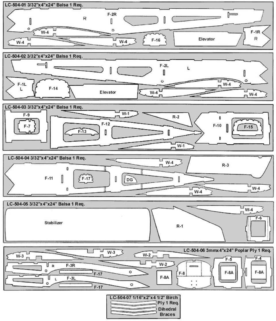
1 Your kit contains the following parts. Please check your kit for any missing or damaged parts before starting construction. Wood Bag: COMPLETE KIT PARTS LIST 1 LC /32"x4"x24" Laser Cut Balsa Sheet 1 LC /32"x4"x24" Laser Cut Balsa Sheet 1 LC /32"x4"x24" Laser Cut Balsa Sheet 1 LC /32"x4"x24" Laser Cut Balsa Sheet 1 LC /32"x4"x24" Laser Cut Balsa Sheet 1 LC /32"x4"x24" Laser Cut Balsa Sheet 1 LC /16"x3"x4 1/2" Laser Cut Birch Ply 6 Leading Edge and Spars 1/4" sq.x24" Balsa Strip 7 Leading Edge & Fuselage Stringers 3/32" sq.x24" Balsa Strip 2 Wing Tips 3/4" Balsa Trianglex7 1/4" 4 Trailing Edge 1/16"x1"x24" Balsa Sheet 2 Rudder Fairing Block 3/4"x3/4"x3 1/4" Balsa Block 2 Main Landing Gear Blocks 3/8"x1/2"x3 1/2" Grooved Hardwood Block 1 Cowl Blocks and servo rails 2 Control Surface Pushrod 1/16"x18" Wire, Threaded One End 2 Throttle and Nose Gear Pushrod Misc. Parts Loose in Box: 1 Center Section & Fuselage Sheet 1/4" sq.x12" Spruce 1/16"x10" Wire, Threaded One End 1/16"x3"x36" Balsa Sheet 1 Fuselage Stringer 3/32"x3/16"x36" Balsa Strip 1 Plan Sheet # I 1 Plan Sheet #2 1 Decal Sheet 1 Instruction Book 2 Main Landing Gear Wire 1 Molded Plastic Cowl 1 Molded Plastic Canopy Hardware Bag: 2 Control Horn Small Nylon Control Horn 4 HornScrew 2-56 x 3/8" Machine Screw 1 Elevator Joiner 1/8" x 3" Birch Dowel 4 Cowl Attach Screw #2 Sheet Metal Screw 4 Nylon Clevis Small Nylon Clevis 2 Wing Dowels 3/16" x 4" Dowels 4 Main Landing Gear Attach Screw Nose Landing Gear Bag: #4 Sheet Metal Screw 1 Nose Gear Wire 3/32" Pre-Bent Wire 1 Nose Gear Bearing Molded Nylon Bearing Block 1 Steering Collar 3/32" Collar 1 Steering Arm 2-56 x 1/2" Threaded Stud 1 Steering Arm Fitting Molded Nylon Fitting 4 Mounting Screws 2-56 x 3/8" Machine Screws 4 Mounting Nuts 2-56 Nuts

2
3 Additional Items Required ( Not Included in Kit) Note: These are parts that we have used and are familiar with. There are many other brands available and you may substitute other items that you are more comfortable with or have on hand. 1 Engine Norvel Big Mig.049 or Norvel Big Mig Motor Mount Dave Brown # Motor Mount Screws and Blind Nuts 3 Hinges Sig Easy Hinges # SH-710 or Du-Bro Kwik Hinge # x3/4" Machine Screws and Blind Nuts Sig #SH- 111 or Du-Bro #129 1 Fuel Tank Sullivan loz. #SS-1 or 2oz. #SS-2 1 1/2-A Fuel Line Sig #SH-288 or Du-Bro #221 4 Servo Connectors Sig #SH-736 or Du-Bro #121 1 White Covering Material 1 Roll Top Flite Monokote and matching paint 1 Red Covering Material 1 Roll Top Flite Monokote and matching paint 8 Rubber Bands (wing attach) 1 Propeller Grish Tornado 6-3 Nylon Propeller #GRlQ1050 Sig #SH /32" Wheel Collars Sig #SH-585 or Du-Bro #138 2 Main Wheels Dave Brown Lectra Lite Wheels # Wheel Bushings Make from K&S Brass Tube #127 1 Nose Wheel Dave Brown Lectra Lite Wheel #5617 General Note: Cover the plans with wax paper before assembling your model to prevent the parts from sticking to the plan. Building the Tail Surfaces 1. Join R-1 and R-2 together over the plan. Temporarily hinge the rudder (R-3) to the fin. Do not glue the hinges at this time. 2. Join the elevators using the 1/8" dowel. Use the plan and the stabilizer as a guide. Trim the dowel if required to achieve the proper length. 3. Temporarily hinge the elevators to the stabilizer. Do not glue the hinges at this time. 4. Sand the tail surfaces smooth and round all of the edges except the bottom edge of the fin. Building the Fuselage 5. Assemble the left fuselage side. Glue parts F-1 (L)and F2 (L) together as shown on the plan. The letter "L" is on the inside of the left fuselage side parts and should face up on all the parts. When the glue is dry, glue part F-3 (L) into position on the inside of the left fuselage side. 6. Build the right fuselage side as you did the left. The parts for the right fuselage side are marked with an "R" on the inside of each piece. 7. Place the right fuselage side on the building board and place formers F-4 and F-5 into position. These formers should be 90 degrees to the Fuselage side. Glue the formers to the fuselage side. Now place the left fuselage side into position and glue to the formers. 8. Gently squeeze the aft end of the fuselage sides together and hold with two clothes pins. Glue the 3/32"x3/16" braces to the front of former F-6 as shown on the plan. Place the formers F-6 and F-7 into position and glue them to the fuselage sides. Glue the aft end of the fuselage sides together making sure that the joint is straight and not leaning to the left or right. 9. Glue the firewall (F-8) into position on the front of the fuselage sides. You must crack the firewall at the dashed line cut into it so the bottom half angles forward as shown on the plan. When the firewall is in place, apply a line of glue to the front and back at the cracked line. 10. Glue part F-9 into position. 11. Glue parts F-10 and F-11 together to form the fuselage top. 12. Place the fuselage top into position. Glue the fuselage top to formers F-4 and F-5 and to the fuselage sides between these two formers. 13. Glue the fuselage top to F-8 and to the fuselage sides from F-8 to F Working from the F-5 to the rear, gently pinch the fuselage sides into contact with the fuselage top and glue together. Now glue the fuselage bottom (F-12) into position.

4 15. Fit parts F-13, F-14, F-15 and F-16 into position on the fuselage top. The formers should be 90 degrees to the fuselage top. Glue both parts F-17 (fuel tank supports) into position. 16. Glue the 3/32" x 3/16"" top stringer into position between formers F-14 and F-17. Now glue the 3/32" sq. stringers into position. 17. Glue the three parts F-8A into position on the front of the firewall. 18. Mount the motor mount on the front of F-8A. Use 4-40 screws and blind nuts. Glue the blind nuts to the rear of the firewall to hold them securely into position. Mount the nose wheel bearing to the firewall with the screws and nuts provided. Notch out F-9 as required for clearance around the lower nuts. 19. Glue parts F-17 into position. 20. Assemble the fuel tank. Drill holes in the firewall for the fuel line, the vent line, the nose wheel steering pushrod and the throttle pushrod. 21. Mount the fuel tank and the fuel and vent lines into the model. The fuel tank can be held into position with thin servo tape between the tank and parts F Remove the motor and mount from the model. 23. Glue the 3/32" x 3/16" strips into position between F-8 and F-3 on the top of the fuselage and between F-8 and F-4 on the bottom of the fuselage. 24. Sheet the top of the fuselage with 1/16" balsa sheet between F-8 and F-13. Sheet the bottom of the fuselage between F-8 and F Sand the entire fuselage smooth all over. 26. Mount the servo rails and servos into position. Make cutouts as required in fuselage top for the servos. 27. Carve and sand the rudder fairing blocks to shape. Glue the stabilizer and the fin fairing blocks to the fuselage. Slide the fin part way into position between the fairing blocks to make sure it will be properly aligned and to maintain the proper spacing between the blocks. 28. When the glue is dry, slide the fin completely into position (do not glue). 29. Temporarily hinge (do not glue) the elevators to the stabilizer. 30. Cut the lower hinge slot in the rudder and the fuselage and then temporarily hinge (do not glue) the rudder to the model. 31. Attach the control horns to the elevator and rudder with 2-56 screws. Install the rudder and elevator pushrods with clevises at the horns and servo connectors at the servos. 32. Install the nose landing wire and steering arm so the arm is on the right side of the firewall. Install the engine and mount back on the firewall. 33. Bend and install the throttle pushrod and the nose gear steering pushrod. Attach these pushrods to the servos with servo connectors. 34. Glue the 1/4" sq. spruce cowl attach blocks to the front of F Carefully trim the cowl and fit it to the fuselage. With the cowl on, attach the propeller to the motor and make sure the cowl is far enough aft to allow propeller clearance. The dimples for the cowl screws on each side of the cowl should line up with the center of the 1/4" sq. spruce strips. Sand the lower comers of F-1 on each side as required to obtain the proper fit. 36. Attach the cowl to the model with the 4 screws provided. 37. Trim the canopy and test fit it to the model. Do not glue it into position at this time.

5 Building the Left Wing 38. Pin the lower 1/4" sq. spar and the lower trailing edge sheet to the left wing plan. 39. Glue the lower plywood dihedral braces to the front and rear of the lower spar. Cut the lower 1/16" sheet for the lower inboard end of the wing and glue in place between the trailing edge and the dihedral brace. 40. Place rib W-1 into position. Use the dihedral gauge to angle the top of this rib toward the tip and glue the rib into position. 41. Glue W-2, W-3 all of the W-4 ribs into position. These ribs should be 90 degrees to the building board. 42. Glue the top 1/4" sq. spar into position. The inboard end ofthe spar should end flush with the face of the W-1 rib. Glue the top plywood dihedral braces to the front and rear of the top spar. 43. Glue the 1/4" sq. leading edge, the 3/32" sq. strips and the top trailing edge sheet to the wing. 44. Add the 1/16" sheet to the inboard end of the wing between the spar and the trailing edge. Use three pieces of 1/16" sheet to sheet the inboard top of the wing from the spar to the leading edge. These pieces go between the 3/32" sq. strips and not on top of them. 45. Remove the wing from the plan and add the lower 1/16" sheet to the inboard end between the spar and the leading edge. Glue the landing gear block into position and drill the 3/32" hole in the landing gear block. 46. Trim and sand the spars, leading edge and the trailing edge flush with the last W-4 rib. Building the Right Wing 47. Place the left wing into position on the end of the right wing plan. Place a spacer under the last W-4 rib to raise the tip 3 3/4" above the building board. The lower 1/16" plywood dihedral braces for the right wing should be flat against the plan. Pin the left wing into this position. 48. Pin the lower spar and the trailing edge sheet into position for the right wing. Glue the spar to the dihedral brace and glue the trailing edge to the left wing. 49. Add the lower rear inboard sheet to the right wing and finish assembling the right wing as you did the left. 51. When the right wing is finished, sand the entire wing smooth and sand the leading edge round. 52. Glue the 3/4" triangle wing tips to the ends of the wing. The front of the tip block should be flush with the leading edge, and the bottom should be flush with the bottom of the W-4 rib. Sand the tip blocks to match the airfoil section of the ribs and then sand them smooth. Covering 53. Remove the cowl, engine, control surfaces, pushrods, landing gear and other items. Sand the entire model smooth with 320 grit sandpaper. 54. Cover the model with your choice of iron on covering materials. 55. Paint the the top of the fuselage and the formers in the cockpit area with black paint. 56. Fit the canopy into position and cut away the covering from the wood where the canopy will fit. Now glue the canopy to the fuselage. 57. Mask off the windows on the canopy and the rest of the fuselage and paint the canopy to match the color of the model. When the paint is dry you can remove the masking. 58. Paint the firewall with fuel proof paint. 59. Apply the decals and other markings as desired. An ultra fine Sharpie Marker can be used to draw panel lines and other details. Paint the wing hold down dowels and the cowl.

6 Final Assembly 60. Install the elevators and then the rudder to the model and glue the hinges in place. 61. Install the pushrods and control horns and connect the pushrods to the servos. 62. Glue the wing hold down dowels into position. 63. Install the landing gear. 64. Install the engine mount to the firewall and bolt the engine to the mount. 65. Install the throttle pushrod and nose gear steering pushrod. 66. Attach the fuel and vent line to the engine and then attach the cowl to the front of the model. 67. Install the receiver and battery pack so that the model balances at the point shown on the plan. Wrap the battery and receiver with foam rubber. If necessary, add weight to the nose or tail until the model balances at the point shown on the plan with the fuel tank empty. Mount the switch in the left fuselage side. Run the receiver antenna through the rear fuselage and out a small hole in the fuselage side just behind F-7 and below the stabilizer. 68. Attach the wing to the model with a minimum of 4 rubber bands on each side. Set the control throws to the measurements shown on the plan. 69. Verify that the model balances at the point shown on the plan before flying. Verify that the control throws are set and that the controls move in the proper direction. 70. Always pre-flight your model thoroughly before each flight. It is your responsibility to verify that your model is airworthy. Always follow established safety guidelines while starting and operating the engine, radio and while flying the model. WARRANTY Herr Engineering Corp. guarantees this kit to be free from defects in both materials and workmanship at the time of purchase. This warranty does not cover any component damaged buy use or modification. In no case shall Herr Engineering Corporation's liability exceed the original cost of the purchased kit. Further Herr Engineering Corp. reserves the right to change or modify this warranty without notice. In that Herr Engineering Corporation has no control over the assembly or use, no liability shall be assumed or accepted for any damage resulting from the use by the user during construction of the kit or the use of the final user assembled product. By the act of building this kit and/or using the final user assembled product, the user accepts all liability. If the buyer and/or user is not prepared to accept all of the liability associated with this product, he is advised to immediately return this kit in new and unused condition to the place of purchase for a full refund. Copyright SIG Mfg. Co., Inc. SIG MFG. CO., INC...Montezuma, Iowa LIMIT OF LIABILITY: In use of our products, Sig Mfg. Co.'s only obligation shall be to replace such quantity of the product proven to be defective. User shall determine the suitability of the product for his or her intended use and shall assume all risk and liability in connection therewith.

Junkers Ju 88 Manual Version 1.2 13 March 2008
 Junkers Ju 88 Manual Version 1.2 13 March 2008 Specifications Wingspan: 49.75 inches Area: 339 square inches Length: 36.12 inches Power: 2x BP21 Brushless 2x Speed-400 Copyright 2007 Thomas A. Jacoby and
Build and Fly the Fokker D- 8
 Details are carefully carried out. Note movable controls The high wing gives it unusual stability Build and Fly the Fokker D- 8 Complete Data From Which You Can Build a Successful Model of a Famous German
Micro. Pitts Special for the RFFS-100 by Chris O Riley
 Micro Pitts Special for the RFFS-100 by Chris O Riley F1 F2 F3 F4 1 2 3 4 All wood 1/32 inch sheet unless otherwise stated. F1 F2 F3 F4 Small balsa blocks for LG reinforcement Small balsa blocks for LG
TopSky DLG Installation Manual
 TopSky DLG Installation Manual Attention: Because after the compound materials solidify, there will be ammonia iris on the surface, which affect the bonding strength afterwards. Please polish with sandpaper
Technical data. Assembly: Introduction. Before starting construction. Equipment needed. Glider or Electro Glider?
 Palio pro S2084 Technical data Wing span: Lenght: Weight: Wing area: Wing loading: El. Motor/ no. of cells: Controls: Introduction 2150 mm 1150 mm 1120 g 1860 g 42 dm2 27 g/dm2 44 g/dm2 600 / 7-8 cells
MS:158 ASSEMBLY MANUAL. Graphics and specifications may change without notice.
 MS:158 ASSEMBLY MANUAL Graphics and specifications may change without notice. Specifications: Wing span ------------------------------70.9in (180cm). Wing area -----------------644.8sq.in (41.6sq dm).
Front landing gear legs. Carve from balsa block
 0 Carve these parts from balsa blocks C-1(2) C-2(3) Note: these cross pieces do not have formers attached. They help establish the proper curve of each fuselage side. Front landing gear legs Carve from
98 Turbine Vulcan Build photos
 98 Turbine Vulcan Build photos Just some of the useful tools needed plus a quality razor plane FUSELAGE Note: Fitting parts back to front is an easy mistake to make with this build, so mark all part with
DL50 Discus Launch Glider
 DL50 Discus Launch Glider DL50 Specifications Length: 39 in. (99 cm.) Wingspan: 50in. (127 cm.) Wing Area: 275in 2 (1774 cm 2 ) Weight: 8oz. (227 g.) Revision History Date Revision Notes/Comments 6/12/2004
How To Build A Roc Plane
 SebArt professional line AngelS EVO 50E ARF ASSEMBLY MANUAL The new AngelS EVO 50E ARF, was designed by the 10 times F3A Italian Champion Sebastiano Silvestri, it is the replica of his 2 meter size F3A
Katana EP. Specifications. 301 sq in / 19.4 sq dm. * Specifications are subject to change without notice.*
 INSTRUCTION MANUAL Katana EP Outrunner Motor Requires: -channel radio w/ micro servos, 0A Brushless ESC, 3 cells.v 00mAh Li-Po battery & charger. Wing Span Wing Area Flying Weight Fuselage Length HIGH
SebArt professional line
 SebArt professional line New Sukhoi 29S 50E ARF ASSEMBLY MANUAL The new Sukhoi 29S 50E ARF was designed by Italy aerobatic pilot, Sebastiano Silvestri and the design is based on of his new Tournament Of
Specifications. *Specifications are subject to change without notice.*
 INSTRUCTION MANUAL Extra 300 EP (0) 50W Motor System Requires : -channel radio w/ mini servos, Outrunner Motor KM37810, w/ Propeller Adaptor HW3010, 0A Brushless ESC with 11x8E proepller, cells 1.8V 300mAh
1/5 PIPER J-3 CUB. Before commencing assembly,please read these instructions thoroughly. Wing Span:84. 0 in / 2130 mm
 INSTRUCTION MANUAL Before commencing assembly,please read these instructions thoroughly. 1/5 PIPER J-3 CUB 1/5 PIPER J-3 CUB Wing Span:8. 0 in / 130 mm Wing Area:968 sq in / 6. 5 sq dm Flying Weight:8.
Super Stunts 60. Specifications. * Specifications are subject to change without notice.*
 A L M O S T- R E A D Y- T O - F LY INSTRUCTION MANUAL Super Stunts 60 0.60-0.75 cu. in. displacement 2-stroke Requires : 4- channel radio w / Specifications 5 standard servos Wing Span Wing Area Flying
Focke-Wulf Fw 190 INSTRUCTION MANUAL SAFETY PRECAUTIONS. Specification:
 Focke-Wulf Fw 90 Specification: Length :9 mm(57") Wing Span :00 mm(70.9") Wing Area :5. sq. dm.0 sq. ft Wing Loading :0. g/sq. dm.7 oz/sq. ft Flying Weight :5. kg(. lbs) Radio :ch& servos Engine :0 -cycle
60 Sbach 342 Electric Aerobatic Aircraft
 60 Sbach 342 Electric Aerobatic Aircraft Specifications: Wing Span: 60 inches Length: 58 inches Power: Hacker A50-14S (or equivalent) Battery: 3800 5-cell LiPo ESC: 60-70 amp Flying Weight: 4.75-5.25 lbs
FREEBIRD THE ORIGINAL D.I.Y. ORNITHOPTER! Tools and Glue. Required Materials
 Do not try to make your ornithopter using "household materials". If you want it to fly, you have to build it right. FREEBIRD THE ORIGINAL D.I.Y. ORNITHOPTER! Wingspan: 16 inches Weight: 1/4 ounce The Ornithopter
WE GET PEOPLE FLYING INSTRUCTION MANUAL
 TM WE GET PEOPLE FLYING INSTRUCTION MANUAL 90% prebuilt Great sport scale appearance Factory installed retracts Precovered in genuine UltraCote Prepainted fiberglass cowl Specifications Wingspan:... 65.5
SebArt professional line AngelS 30E ARF
 SebArt professional line AngelS 30E ARF ASSEMBLY MANUAL The new AngelS 30E ARF, was designed by the 10 times F3A Italian Champion Sebastiano Silvestri, it is the replica of his 2 meter size F3A competition
INSTRUCTION MANUAL. 90% Pre-Built Build as Tail dragger or Tricycle Landing Gear System All Hardware Included
 90% Pre-Built Build as Tail dragger or Tricycle Landing Gear System All Hardware Included INSTRUCTION MANUAL Specifications for.40 Wingspan: 52-3/4" Length: 48" Wing Area: 593 sq. in. Weight (Approx):
Assembly and Operating Manual Nano warbirds FW 190 Specification: *Length: 18 1/2"(470mm) *Wing Span: 21 7/10"(550mm)
 *Wing Span: 21 7/10(550mm)") Assembly and Operating Manual Nano warbirds FW 190 Specification: *Length: 18 1/2"(470mm) *Wing Span: 21 7/10"(550mm) *Flying Weight: 6 1/2 oz (185g) Dear customer, Congratulations on your choice of a
Assembly and Operating Manual Nano warbirds FW 190 Specification: *Length: 18 1/2"(470mm) *Wing Span: 21 7/10"(550mm) *Flying Weight: 6 1/2 oz (185g) Dear customer, Congratulations on your choice of a
40% EXTRA 330L ARF Manual
 40% EXTRA 330L ARF Manual Please read through the entire manual first. It contains important instructions and warnings concerning the finishing of the model. WARRANTY AND PRODUCT DISCLAIMER Radiowave Hobby
REALISTIC FUN SCALE MODEL HUGE, 84 WINGSPAN (IMAA Legal) 1/4 SCALE MODEL BUILDS QUICKLY
 1/4 SCALE MODEL BUILDS QUICKLY") 84" Fun Scale Fly Baby REALISTIC FUN SCALE MODEL HUGE, 84 WINGSPAN (IMAA Legal) 1/4 SCALE MODEL BUILDS QUICKLY READ THROUGH THIS INSTRUCTION MANUAL FIRST. IT CONTAINS IMPORTANT INSTRUCTIONS AND WARNINGS
84" Fun Scale Fly Baby REALISTIC FUN SCALE MODEL HUGE, 84 WINGSPAN (IMAA Legal) 1/4 SCALE MODEL BUILDS QUICKLY READ THROUGH THIS INSTRUCTION MANUAL FIRST. IT CONTAINS IMPORTANT INSTRUCTIONS AND WARNINGS
RETRACTABLE LANDING GEAR
 HUGHES H-1 RETRACTABLE LANDING GEAR INSTALLATION INSTRUCTIONS Congratulations on your decision to add retractable landing gear to your RC model of the Hughes H-1. Though originally conceived simply for
Gripper Kit for the Boe-Bot Robot (#28202)
") 599 Menlo Drive, Suite 100 Rocklin, California 95765, USA Office: (916) 624-8333 Fax: (916) 624-8003 General: [email protected] Technical: [email protected] Web Site: www.parallax.com Educational: www.stampsinclass.com
599 Menlo Drive, Suite 100 Rocklin, California 95765, USA Office: (916) 624-8333 Fax: (916) 624-8003 General: [email protected] Technical: [email protected] Web Site: www.parallax.com Educational: www.stampsinclass.com
harbor cub Electric Remote Control Airplane Model 92906 assembly & Operating Instructions
 harbor cub Electric Remote Control Airplane Model 92906 assembly & Operating Instructions IMPORTANT: If damage is caused due to a crash, your warranty is void. Visit our website at: http://www.harborfreight.com
Sopwith Camel 60 ARF
 Sopwith Camel 60 ARF Assembly manual Specifications Wingspan... 61 in (1551mm) Wing Area... 1236 sq in (79.7 sq dm) Length... 41.3 in (1050mm) Weight... 7.25 8.75 lb (3.3kg 4.0kg) Table of Contents Contents
MGB Chrome Bumper Conversion
 MGB Chrome Bumper Conversion Installation Instructions For 1974 1/2-1980 MGB This kit requires cutting, welding, and painting. Professional installation recommended. Note: Every MGB body is slightly different
Introduction. Table of Contents. Specifications
 Assembly Manual Table of Contents Introduction...2 Table of Contents...2 Warning...3 Additional Required Equipment...3 Additional Tools and Adhesives...3 Contents of Kit/Parts Layout...4 Warranty Information...5
Skywalker X8. Assembly manual January 2013
 Skywalker X8 Assembly manual January 2013 This Manual Was Created by Ray Grauberger www.raygrauberger.com Technical Data This is the X-8 FPV wing from Skywalker Technology. The BIG FPV wing! The X-8 has
Lightening Holes. Plastics and Fiberglass. Engine Options. Retract Options. CAD Design. CAD Drawn Plans. Flaps. Cockpit Detail.
 messerschmitt ME109E The ME109 was the standard by which all other fighters of WWII were judged. It served the Luftwaffe in almost every capacity, from interceptor to night-fighter to ground attack and
Assembly Manual For. Dolphine Jet. Wingspan: 88 in Wingarea: 1479.8 sp in Length: 78.8 in Engine: 50CC. www.pilot-rc.com
 Assembly Manual For Dolphine Jet Wingspan: 88 in Wingarea: 1479.8 sp in Length: 78.8 in Engine: 50CC www.pilot-rc.com INTRODUCTION Thank you for purchasing our Dolphin Jet. we strive to achieve the real
Sundowner 36 ARF Assembly Manual
 Sundowner 36 ARF Assembly Manual Notice All instructions, warranties and other collateral documents are subject to change at the sole discretion of Horizon Hobby, Inc. For up-to-date product literature,
INSTRUCTION MANUAL. 254 cm 154 cm 3429 sq cm 5.9-7.3 kg
 TM INSTRUCTION MANUAL 100" Wingspan 90% pre-built Covered in Cub yellow WorldTex fabric covering Includes Scale detailing instructions Cub yellow fiberglass cowl included IMAA legal All hardware included
Build Your Own Solar Car Teach build learn renewable Energy! Page 1 of 1
 Solar Car Teach build learn renewable Energy! Page 1 of 1 Background Not only is the sun a source of heat and light, it s a source of electricity too! Solar cells, also called photovoltaic cells, are used
P-51 Mustang 60 ARF Assembly Manual
 P-51 Mustang 60 ARF Assembly Manual Specifications Wingspan: 65 in (1653mm) Length: 57 in (1448mm) Wing Area: 743 sq in (47.9 sq dm) Weight: 9.25 10.0 lb (4.2 4.5 kg) Wing Loading: 29 31 oz per sq ft Radio:
How To Build A Plane From Scratch
 BUILDING INSTRUCTIONS FOR THE SOLANGE (SUN ANGEL) The Solange has had a very long period in which to develop. It was originally designed for flying from the Bwlch in South Wales during 1993 as a glider
INSTALLATION INSTRUCTIONS FOR G205 AND G207 STICK GRIPS
 1341 Distribution Way STe 15, Vista, A 92081 USA Ph 760.599.4720 Fx 760.599.4383 INSTALLATION INSTRUTIONS FOR G205 AND G207 STIK GRIPS G205 G207 Warning: Installation and use of Ray Allen ompany products
INSTRUCTIONS THOROUGHLY BEFORE BEGINNING***************
 Bill of Materials: RAC0012 Green Wing Aerodynamic Skirt Kit Item Part Number Description Quantity 1 RMC0218 Gen 2 Trailer Skirt Roadside 1 2 RMC0219 Gen 2 Trailer Skirt Curbside 1 3 RMC0041 Trailer Skirt
P-51D Mustang Sport 40 ARF Assembly Manual
 P-51D Mustang Sport 40 ARF Assembly Manual Specifications Wingspan:... 58.25 in (1480mm) Length:... 50.4 in (1281mm) Wing Area:...626 sq in (40.39 sq dm) Weight:... 6.5 7 lb (2.9 3.2 kg) Radio:...4- to
Have fun, nevertheless!
 Nanomum The Nanomum is a small pusher gyro for flying indoors or outdoors in very calm weather. It's got a dc head and is easy to build and easy to fly - I hope. Specs: AUW 70 g / 2.5 oz. Rotor diameter:
SILVER WINGS 1/32 GLOSTer gladiator Mk1/mk2 build guide
 SILVER WINGS 1/32 GLOSTer gladiator Mk1/mk2 build guide Parts Cleanup As with other Silver Wings kits, parts cleanup is fairly simple, and due to the soft resin they use for their kit, a sprue cutter can
A high performance model glider for slope soaring, designed by James D Hammond and brought to you by Sloperacer.
 Schwing 88 A high performance model glider for slope soaring, designed by James D Hammond and brought to you by Sloperacer. Thank you for purchasing the Schwing 88. The design remit was to extend the flight
P-40B Warhawk 50 ARF Assembly Manual
 P-40B Warhawk 50 ARF Assembly Manual NOTICE All instructions, warranties and other collateral documents are subject to change at the sole discretion of Horizon Hobby, Inc. For up-to-date product literature,
DIY CABINET REFACING INSTALLATION GUIDE
 DIY CABINET REFACING INSTALLATION GUIDE CABINET REFACING INSTALLATION Are you ready to reface your outdated cabinets? This guide will show you how to install your new Facelifters Cabinet Refacing Products
Note there are many options for how this model can be built, including:
 Page 1 Introduction Welcome to the Su-37 park jet! This model was designed for twin Littlescreamers Park Jet (LSPJ) motors and features a working 3- axis thrust vectoring (TV) system, just like the real
BUILDING INSTRUCTION SAL-DLG MINI-FIREWORKS. MINI-Fireworks building instruction May 2015. www.pcm.at 1
 Wingspan [mm]: 950 Aspect ratio: 7,7 Wing area [dm2]: 11,7 Wing loading [g/dm²] : 12-13 Takeoff weight [g]: 155 (Mini-S), 165 (Mini-Q) Airfoil: AG03 mod 3-side-view version with ailerons BUILDING INSTRUCTION
DeNight Special 50 ARF Assembly Manual
 DeNight Special 50 ARF Assembly Manual Specifications Wingspan... 58.5 in (1486mm) Length... 45.4 in (1153 mm) Wing Area... 626 sq in (40.4sq dm) Weight... 6 1/4 7 lb (2.8 3.2 kg) Radio... 4-channel w/4
Assembly Manual For. 30cc 88 Skywolf. www.pilot-rc.com. Note: some photos on the manual is not from Skywolf. But the installation way is the same.
 Assembly Manual For 30cc 88 Skywolf Wingspan: 88 in www.pilot-rc.com Wingarea: 1479.8 sp in Length: 78.8 in Engine: 50CC Note: some photos on the manual is not from Skywolf. But the installation way is
Build a Junior Solar Sprint Model Car Kit Materials: 1 PITSCO Ray Catcher Sprint Kit or Solar Made Junior Solar Sprint Kit 1 White Sheet of Plastic
 Build a Junior Solar Sprint Model Car Kit Materials: 1 PITSCO Ray Catcher Sprint Kit or Solar Made Junior Solar Sprint Kit 1 White Sheet of Plastic Coated Paper 2 Balsa Sheets (10-1/2 x4 x3/16 ) 2 Alligator
BUILDING INSTRUCTION ERWIN XL slope ERWIN XL ultralight - ERWIN XL ultralight Elektro. Erwin XL building Instruction October 2012. www.pcm.
 Wing span [mm]: 3000 Aspect ratio: 14,67 Wing area [dm2]: 61,33 Wing loading: Erwin XL slope: 45,6-70,1 Erwin XL ultralight: 20,4 Erwin XL ultralight Elektro: 23,6-24,5 Weight [g]: Erwin XL slope: 2800-4300
Toledo Special 40 Assembly Manual
 Toledo Special 40 Assembly Manual Specifications Wingspan:... 69.5 in (1765.3mm) Length:... 50.8 in (1290.75mm) Wing Area:...702.8 sq in (45.3 sq dm) Weight:... 5.5 6.25 lb (2.49 2.83 kg) Radio:...4-channel
Use blue thread lock on all bolts and blind nuts! Assembly Manual for Yak 54 -by Pilot RC
 Assembly Manual for Yak 54 -by Pilot RC 1. Inventory the parts in your kit and familiarize yourself with the assembly manual before starting on this project. If this is your first aerobatic model, get
www.cornholesupplies.com
 www.cornholesupplies.com How To Build Regulation Cornhole Boards Home of the Original Cornhole Bags and Boards Supply List: 1-4' X 8' Piece of Plywood (pre sanded) 4-2" X 4" X 8' Studs (2 by 4s make sure
Best Barns USA Assembly Book
 Best Barns USA Assembly Book Revised November 27, 2013 the Easton - R 12'x 20' Manufactured by Reynolds Building Systems, Inc. 205 Arlington Drive Greenville, PA 16125 724-646-3775 This manual is copyrighted.
Go-kart for little race-drivers
 Go-kart for little race-drivers Drill and drive. Go-kart What it lacks in speed, it more than makes up for in fun: the go-kart will excite little race-drivers. 1 Introduction It s only a go-kart, but it
PRODUCT MANUAL SPECIFICATIONS SAFETY PRECAUTIONS. 1460mm/57.48in 1112mm/43.78in 27.74dm²/429.96in² 1600g/56.50oz 57.68g/dm²
 SPECIFICATIONS SAFETY PRECAUTIONS PRODUCT MANUAL Wing span: Length: Wing area: Flying weight: Wing loading: 1460mm/57.48in 1112mm/43.78in 27.74dm²/429.96in² 1600g/56.50oz 57.68g/dm² This electric R/C model
Assembly Manual For. Wingspan: 88 in Wingarea: 1479.8 sp in Length: 78.8 in Engine: 50CC
 Assembly Manual For 50cc aerobatic plane Wingspan: 88 in Wingarea: 1479.8 sp in Length: 78.8 in Engine: 50CC www.pilot-rc.com INTRODUCTION Thank you for purchasing our new 50cc aerobatic plane. we strive
Mini Edge 540 3D. Assembly Manual
 Mini Edge 540 3D Assembly Manual 2 Table of Contents Introduction...2 Specifications...2 Contents of Kit/Parts Layout...3 Required Electronics & Accessories...4 Recommended High Performance Motor Setup*...4
How to Build a Poker Table
 How to Build a Poker Table www.pokertablematerials.com 10-Person Poker Table- 96 x 48 These are step by step instructions for building a poker table. The table will measure 48" x 96" and have a 4" wide
PT-19 ARF. Assembly Manual. Specifications
 PT-19 ARF Assembly Manual Specifications Wingspan: 45 in (1440mm) Length: 36 in (910mm) Wing Area: 310 sq in (19.9 sq dm) Weight w/o Battery: 22 24 oz (680 740 g) Weight w/battery: 27 29 oz (820 880 g)
INSTRUCTION MANUAL TOOLS NEEDED FOR ASSEMBLY: OPTIONAL FINISHING MATERIALS: Champaign, Illinois (217) 398-8970 E-mail: partssupport@hobbico.
 398-8970 E-mail: partssupport@hobbico.") INSTRUCTION MANUAL Thank you for purchasing the Hobbico Ultra-Tote! You have purchased one of the finest values available in field support equipment. We think you will be impressed with the design and
INSTRUCTION MANUAL Thank you for purchasing the Hobbico Ultra-Tote! You have purchased one of the finest values available in field support equipment. We think you will be impressed with the design and
Gravity Racing Challenge STEM Team Competition Open Class High School Division Car Assembly Plans And Rules
 Gravity Racing Challenge STEM Team Competition Open Class High School Division Car Assembly Plans And Rules 1 Table Of Contents Introduction...Page 3 Floorboard...Page 4 Step One Steering Stop Installation...Page
Super Stock Car Plans. A comprehensive guide to help you build an official Soap Box Derby Super Stock Car
 Super Stock Car Plans A comprehensive guide to help you build an official Soap Box Derby Super Stock Car For a comprehensive video to help you build a Super Stock Car please visit https://www.youtube.com/aasbdorg
INSTALLATION INSTRUCTIONS for Bifold Doors (JII103)
") Thank you for selecting JELD-WEN products. Attached are JELD-WEN s recommended installation instructions for premium composite, hollow and solid core molded Bifold Doors. Bifolds are designed for fast
Thank you for selecting JELD-WEN products. Attached are JELD-WEN s recommended installation instructions for premium composite, hollow and solid core molded Bifold Doors. Bifolds are designed for fast
O P E R A T I N G I N S T R U C T I O N S
 O P E R A T I N G I N S T R U C T I O N S CAUTION The Phase 3 Models Fantom is designed for intermediate to advanced pilots. It's not intended for beginners. It is not a trainer! Specifications AND Features:
Assembly and Usage Instructions
 Assembly and Usage Instructions A Product 5885 West Van Horn Tavern Road Columbia, MO 65203 www.caldwellshooting.com Instruction #1001667 Limited Warranty Every Caldwell product is warrantied to be free
Triple Threat 3-in-1 Game Table 3 IN 1 GAME TABLE
 NG0M Triple Threat 3-in- Game Table 3 IN GAME TABLE Thank 3 in Y Game Table Thank you for your purchase of our product. We work around the clock and around the globe to ensure that our products maintain
INSTRUCTION MANUAL. Black Angel. www.copterx.com. Features. Kit Helicopter. Copyright 2009 KY MODEL Company Limited.
 INSTRUCTION MANUAL Features - Carbon fiber main blade, tail blade, fly paddle, tail fin for extra weight saving and durability. - CNC machined high grade aluminum rotor head and tail gear box to ensure
Stair Parts Installation. Tricks
 Stair Parts Installation Tips & Tricks Introduction Your DIY staircase guide Welcome to the Stairpart home installation guide. Your stairway is both a functional and focal point in your home, so keeping
INSTRUCTION MANUAL WARRANTY
 INSTRUCTION MANUAL Wing Span - 44-3/4 in Wing Area - 305.7 sq in Weight - 9.5 13.5 oz Wing Loading - 4.5 6.4 oz/sq ft Fuse Length - 28-5/8 in MADE IN USA WARRANTY Great Planes Model Manufacturing Co. guarantees
Navico-Northstar 2kW JRC Radar Package, Scanner Cable Removal and Replacement
 Navico-Northstar 2kW JRC Radar Package, Scanner Cable Removal and Replacement This work instruction describes the methods and means for which to remove and reinstall optional scanner cable configurations
Post Mount Light Installation*
 Post Mount Light Installation* *For the general installation of most Post Mount Spotlights, many vehicles may need slight modifications to these instructions. You will need the following tools: High torque
Brief introduction----------------------------------------------------------------------------03
 A-1 skyraider Brief introduction----------------------------------------------------------------------------03 Specification----------------------------------------------------------------------------------03
Sig Mfg. Co., Inc...401-7 South Front Street...Montezuma, Iowa 50171
 The Spacewalker II Story Sig Mfg. Co., Inc...401-7 South Front Street...Montezuma, Iowa 50171 In 1986, inspired by the classic PT-19 and Ryan millitary trainers of WWII, North Carolina EAA member Jesse
BUILDING THE PIPER J-3 CUB
 BUILDING THE PIPER J-3 CUB INTRODUCTION Top Flite is proud to present it's large, scale version of the legendary J-3 PIPER CUB. Few aircraft in the history of aviation have had the overall appeal of this
ELECTRONICS G H I J K L M
 ELECTRONICS TM LASER INSTALLATION INSTRUCTIONS PARTS KIT Parts Kit includes the following: A- (1) Universal Mounting Bracket A B- (1) Red L.E.D. Laser Alert Light C- (1) Piezo Beeper w/ O Ring Tape D-
Assembly GUIDE. display wine cellar kits. Required. Suggested. Questions? 888.373.6057. or visit wineracksamerica.com
 Page 1 Middle Ladder End Ladder Display Tray Screwless Connector Package Contents * All models follow the same assembly procedure varying only in the number of middle ladders your rack will require. Depending
Instruction Manual Specification:
 Instruction Manual Specification: Wingspan: 1855mm (73 ) Length: 1970mm (77.5 ) Weight: 7.5-9Kg (Approx.) Radio: 6+ Channel (Required) Turbine: 50-100N (5-10Kg) (Recommended) Introduction Congratulations
QSI Auto-Focus Mounting Bracket
 QSI Auto-Focus Mounting Bracket The camera mounting bracket makes extensive use of sliding dovetails. The dovetail joint gets immense strength from a trapezoidal pin trapped in a slot. The internal flats
SebArt professional line
 SebArt professional line Mini Avanti 1.4m ARF EDF or P20 micro-turbine ASSEMBLY MANUAL The all new Mini Avanti Jet 1.4m ARF was designed by Italy aerobatic pilot Sebastiano Silvestri. This sport ARF jet-model
1. Lay out 2 pieces of 7/8" tubing and mark for bending as shown. Remember that the bend is in the shaded area as shown below in Figure 1.
 MINI BIKE PLANS Page 1 INTRODUCTION Before starting to build your Mini-Bike, be sure that you have all the parts shown on the material list. You will note that tubing has been used in the construction.
How to Build Your Own CornHole Game
 How to Build Your Own CornHole Game DIMENSIONS Here is a diagram with the basic measurements for the Cornhole board game. SUPPLIES 1/2 thick sheet of plywood one 4 x4 or two 2 x4 s 8 long 2 4 s (4) 4 1/2
Here is your set of Detailed Plans from Copyright 2004 All Rights Reserved
 Here is your set of Detailed Plans from Copyright 2004 All Rights Reserved Materials for the House Here is the list of materials you will need to construct the basic house then to cover it with roofing
SIG MFG. CO., INC. PO Box 520 Montezuma, IA 50171-0520 www.sigmfg.com
 Kit No. SIGRC67EGARF DESIGNED FOR GLOW OR ELECTRIC POWER Wingspan: 70 in. (1778 mm) Wing Area: 900 sq.in. (58.1 dm 2 ) Length: 57 in. (1447 mm) Flying Weight: 6-6.25 lbs. (2720-2835 g) Wing Loading: 15-16
Children s Furniture Projects
 This is an excerpt from the book Children s Furniture Projects by Jeff Miller Copyright 2002 by The Taunton Press www.taunton.com CHILD S ROCKER KIDS ARE ALWAYS IN MOTION. It s not easy to get them even
Tango 40 ARF Assembly manual
 Tango 40 ARF Assembly manual Specifications Wingspan... 48.2 in (1225mm) Wing Area... 747 sq in (48.2 sq dm) Length... 49.4 in (1255mm) Weight... 5.5 6.5 lb (2.5 kg 2.95 kg) Engine....56.82 Four-Stroke....40.52
Slide the new steering column shaft through the steering column from the driver compartment.
 Slide the new steering column shaft through the steering column from the driver compartment. Push the column shaft through the steering column until the machined end is out past the column lower bushing.
SIG MFG. CO., INC. PO Box 520 Montezuma, IA 50171-0520 www.sigmfg.com
 Shown with optional 2 Spinner (not included) Wing Span: 78 in. (1980 mm) Wing Area: K 1148 sq. in. (74.1 dm2) Length: 65 in. (1651 mm) Flying Weight: 8-8.5 lbs. (3629-3856 g) Wing Loading: K16.0-17.0 oz./sq.ft.
Modular Locomotive System Instruction Manual for HBK8 George Body Kit
 Modular Locomotive System Instruction Manual for HBK8 George Body Kit Roundhouse Engineering Co. Ltd. Units 6-10 Churchill Business Park. Churchill Road, Wheatley. Doncaster. DN1 2TF. England. Tel. 01302
T-28 Trojan Instruction Manual Charge-and-Fly Park Flyer
 T-28 Trojan Instruction Manual Charge-and-Fly Park Flyer Wingspan: 44 in (1118mm) Length: 36 in (914mm) Weight (RTF): 30 oz (875 g) Servos: Four 3-wire servos Motor: PKZ 480 960Kv outrunner brushless motor
50cc Edge 540T ARF. Instruction Manual. Copyright 2009 Extreme Flight RC
 50cc Edge 540T ARF Instruction Manual Copyright 2009 Extreme Flight RC 1 Please take a few moments to read this instruction manual before beginning assembly. We have outlined a fast, clear and easy method
AIRCRAFT GENERAL www.theaviatornetwork.com GTM 1.1 2005 1-30-05 CONTENTS
 www.theaviatornetwork.com GTM 1.1 CONTENTS INTRODUCTION... 1.2 GENERAL AIRPLANE... 1.2 Fuselage... 1.2 Wing... 1.2 Tail... 1.2 PROPELLER TIP CLEARANCE... 1.2 LANDING GEAR STRUT EXTENSION (NORMAL)... 1.2
EZ-Steer Assisted Steering System
 EZ-Steer Assisted Steering System Installation Instructions Platform Kit P/N 53059-54 Case IH CVX 1135 CVX 1145 CVX 1155 CVX 1170 CVX 1190 CVX 1195 CVX 135 CVX 145 CVX 155 CVX 175 CVX 195 New Holland TVT
ASSASSIN Building Instructions by CRASHTESTHOBBY.COM
 ASSASSIN Building Instructions by CRASHTESTHOBBY.COM The Assassin is the toughest plane on the planet!!! The Assassin can take more abuse and keep on flying better than any other plane we have seen. It
SLACK PERFORMANCE KARTS
 SLACK PERFORMANCE KARTS SET UP GUIDE Thank you for purchasing a 2013 Slack Axiom Chassis. Performance Mfg. strives to provide you with the very best chassis and components on the market today. Your satisfaction