Space Shuttle Propulsion PROPULSION SYSTEM. Space Shuttle Main Engine (SSME)
|
|
|
- Myrtle Walker
- 9 years ago
- Views:
Transcription
1 Space Shuttle Propulsion PROPULSION SYSTEM Space Shuttle Main Engine (SSME)
")
2 Space Shuttle Main Engine (SSME) PROPULSION SYSTEM Mounted in a triangular pattern in the orbiter's aft fuselage, the three Space Shuttle main engines (SSME's) produce a total sea-level thrust of million pounds (1.41 million pounds at vacuum). Each engine is capable of producing 6.5 x 10 6 horsepower for a combined total of 19.5 x 10 6 horsepower. Liquid oxygen (L02) and liquid hydrogen (LH2), cryogenic propellants contained in the external tank, are supplied to the three engines at a total flowrate of 3090 LBM per second. Each engine operates with a fixed nozzle area ratio of 77.5:1 at a mixture ratio (L02/LH2) of 6:1 and a chamber pressure of 2970 psia, producing a rated sea-level thrust of 375,000 pounds and a vacuum thrust of 470,000 pounds. The high chamber pressure (significantly higher than previous engines) and flowrate (1030 LBM per second) for each engine is made possible by the use of the efficient staged-combustion engine cycle. This cycle allows high turbopump propellant discharge pressures (7600 psia for L02, and 6200 psia for LH2) which are necessary to overcome pressure losses within the engine and still maintain the 2970 psia chamber pressure. The engines can be throttled over a thrust range of 65 to 109 percent of the rated power level, to a maximum thrust of 512,000 pounds per engine. This throttling capability enables the crew to tailor engine thrust to mission needs and limit the orbiter's acceleration to 3 g's. The engines are bearing-mounted and capable of gimbaling degrees in pitch and +8.5 degrees in yaw for orbiter steering control. The Shuttle main engine is the first to use a built-in electronic digital controller to accept commands from the orbiter for engine start, shutdown, and change in throttle setting. It will also monitor engine operation and, in case of failure, will automatically correct the problem or shut down the engine safely. Able to operate for 7.5 hours of accumulated firing time, SSME's are reusable for up to 55 missions before requiring major maintenance or overhaul.
 and liquid hydrogen (LH2), cryogenic propellants contained in the external tank, are supplied to the three engines at a total flowrate of 3090 LBM per second.")
3 PROPULSION SYSTEM External Tank

4 PROPULSION SYSTEM External Tank The external tank (ET) supplies the orbiter main propulsion system with liquid hydrogen (LH2) and liquid oxygen (L02) at prescribed pressures, temperatures, and flow rates. Both the LH2 and L02 tanks are equipped with vent and relief valves to permit loading, pressurization, and relief functions. Tank level sensors provide for propellant loading and SSME shutdown signals. The ET is thermally protected with a nominal 1-inch-thick spray-on foam insulation (SOFI), employing additional SOFI and a charring ablator (SLA 561) to withstand localized high heating. Since the ET is an expendable element, the ET subsystems are designed for single usage to minimize costs. The ET reacts the solid rocket booster (SRB) thrust through its intertank structure and provides attach structure to the orbiter to react the SSME thrust. At liftoff, the ET contains approximately 1.58 million pounds of usable propellant. At main engine cutoff (MECO), the ET is separated from the orbiter before orbital velocity is achieved. The ET then proceeds on a ballistic reentry path and breaks up prior to impact in the ocean. The ET consists of a forward L02 tank, an unpressurized intertank, and an LH2 tank. The L02 tank (volume 19,500 ft 3 ) is an aluminum alloy monocoque structure composed of a fusion-welded assembly of performed chem-milled gores, panels, machined fittings, and ring chords. The L02 tank is designed to operate at a nominal pressure range of 20 to 22 psig. The tank contains antislosh and antivortex baffles as well as an antigeyser system to control conditions. A 17-inch diameter feedline conveys propellant through through the inter-tank and externally aft to the ET/orbiter disconnect. The tank's double wedge nose cone reduces drag and heating, serves as a lightning rod, and contains an ascent air data system. The intertank is a semimonocoque cylindrical structure with flanges on each end for joining the L02 and LH2 tanks. The intertank contains the SRB thrust beam and fittings which distribute SRB loads to LO2 and LH2 tanks. The intertank houses ET instrumentation components, and provides an umbilical plate which interfaces with a ground facility arm. The umbilical plate accommodates purge gas supply, hazardous gas detection, and hydrogen gas boiloff during ground operations. The intertank consists of mechanically joined skin, stringers, and machined panels of aluminum alloy. The intertank is vented in flight.
, employing additional SOFI and a charring ablator (SLA 561) to withstand localized high heating.")
5 PROPULSION SYSTEM External Tank The LH2 tank (volume - 55,552 ft 3 ) is a semimonocoque structure composed of fusion-welded barrel sections, five beam ring frames, and forward and aft 0.75 ellipsoidal domes. The LH2 tank is designed to operate at a nominal pressure of 32 to 34 psia. The tank contains an antivortex baffle and a siphon outlet to transmit propellant to the ET/orbiter disconnect through a 17-inch-diameter line. The LH2 tank has provisions for the ET/orbiter forward attach strut, two ET/orbiter aft attach fittings, the thrust distribution structure, the aft SRB/ET stabilizing strut attachments, and the aft ET/SRB rear attach fittings.

6 PROPULSION SYSTEM Solid Rocket Booster
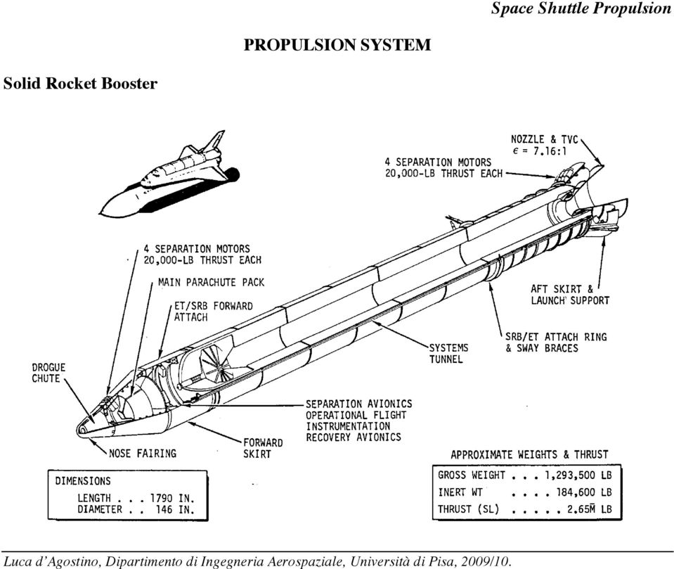
7 PROPULSION SYSTEM Solid Rocket Booster Two solid rocket boosters (SRB s) burn in parallel with the orbiter main propulsion system (MPS) to provide initial ascent thrust. Primary elements of the booster are the motor, including case, propellant, igniter, and nozzle; structural systems; separation, operational flight instrumentation (OFI), and recovery avionics; separation motors and pyrotechnics; and deceleration system, range safety destruct system, and thrust vector control (TVC) subsystems. Each SRB weighs approximately million pounds and produces 2.65 million pounds of thrust at sea level. The propellant grain is shaped to reduce thrust approximately one-third at 55 seconds after liftoff to prevent overstressing the vehicle during the period of maximum dynamic pressure. The grain is of conventional design, employing a star perforation in the forward motor closure and a double truncated cone perforation in each of the segments and aft closure. The contoured nozzle expansion ratio (area of exit to area of throat) is The SRB TVC, which is a closed-loop hydraulic system with power provided by redundant APU's and hydraulic pumps, has an omni-axial gimbal capability of 7.1 degrees which, in conjunction with the orbiter main engines, provides the flight control during the Shuttle boost phase. A segmented case design affords maximum flexibility in fabrication and ease of transportation and handling. A cone-shaped skirt at the aft end of each of the SRB s carries the aft loads between the SRB and the mobile launch pad (MLP). Two lateral sway braces and a diagonal attachment at the aft frame provide the structural attachment between the SRB and external tank. The SRB forward attachment to the external tank is by a single thrust attachment at the forward end of the forward skirt. The same forward skirt is used for attaching the main parachute riser attachments. The SRB s are released from the ET by pyrotechnic separation devices at the forward thrust attachment and the aft sway braces. Eight separation motors on each SRB, four aft and four forward, separate the SRB from the orbiter and external tank. The SRB forward section provides installation volume for the SRB electronics, recovery gear, range safety destruct system, and forward separation rockets. It also houses the parachute deceleration subsystem which consists of a pilot parachute, a ribbon drogue parachute, and three ribbon main parachutes.

8 Space Shuttle Propulsion PROPULSION SYSTEM Main Propulsion Subsystem

9 PROPULSION SYSTEM Main Propulsion Subsystem

10 PROPULSION SYSTEM Main Propulsion Subsystem The Space Shuttle main propulsion subsystem (MRS) is shown and consists of the Space Shuttle main engines (SSME's), external tank (ET), propellant feed, management, fill and drain, conditioning, pressurization control, pneumatic supply, and purge. These subsystems are further illustrated in a subsequent schematic diagram of the MPS. Each of the three SSME's operates with a fixed nozzle area ratio of 77.5:1 at a mixture ratio (L02/ LH2) of 6:1 by weight and a chamber pressure of 3000 psia to produce a rated sea-level thrust of 375,000 pounds and a vacuum thrust of pounds. The engines can be throttled over a thrust range of 65 to 109 percent of the rated thrust level. This allows orbiter acceleration to be limited to 3 g's. The engines are capable of being gimbaled ±10.5 degrees in pitch and ±8.5 degrees in yaw for flight control during the orbiter boost phase. The 1,550,000 pounds of usable ascent propellants required for SSME operation are provided from the external tank. The ET is expended after main engine cutoff (MECO) but prior to achieving orbit. The ET impacts in the ocean after separating from the orbiter and is not reusable. Five MPS fluid lines interface with the ET through disconnects located at the bottom of the orbiter aft fuselage. The three hydrogen disconnects are mounted on a carrier plate on the left side of the orbiter (facing forward), and the two oxygen disconnects are mounted on the right side. Ground servicing of the MPS is accomplished through umbilicals on both sides of the aft fuselage (hydrogen is serviced from the left side facing forward, oxygen from the right side). The orbiter MPS engines burn for approximately eight minutes, from just prior to liftoff until MECO For the first two minutes, the MPS engines operate in parallel with the solid rocket booster (SRB) motors. The MPS and SKB provide the velocity increment necessary to almost achieve the initial mission orbit. The final small velocity increment to achieve the desired orbit is provided by the orbit maneuvering subsystem.
 of 6:1 by weight and a chamber pressure of 3000 psia to produce a rated sea-level thrust of 375,000 pounds")
11 Main Propulsion Subsystem Schematic PROPULSION SYSTEM

12 Main Propulsion Subsystem Schematic PROPULSION SYSTEM The MPS consists of the following subsystems: propellant feed, propellant fill and drain, propellant conditioning, pressurization control, gaseous helium (GHe) pneumatic supply, gaseous nitrogen(gn2) purge, propellant management, main engines, and external tank. The schematic does not show the pneumatic supply or GN2 purge. The propellant feed supplies propellants (LH2 and L02) to the main engines from the ET The propellant fill and drain provide propellants to the ET during loading and propellant drain capability on the ground. The propellant conditioning system provides conditioned propellants to the SSME's for engine start. The pressurization control maintains the proper pressures in the ET. Tank prepressurization with ground-supplied GHe plus hydrostatic head provides the required pressure to the engine pump inlets for the starting transient. Following engine thrust build up, tank pressure is maintained with vaporized propellants extracted from the engines. The ET ullage pressures during boost operation will be maintained at 20 to 22 psig in the L02 tank and 32 to 34 psia in the LH2 tank. Pneumatics are supplied by a 4000-psi helium storage system with 750-psi regulation for valve actuation, SSME purge and backup SSME shutdown. Expulsion of residual propellants after main engine cutoff (MECO) and repressurization of MPS lines for reentry are provided by a 20-psi helium regulated supply. The GN2 purge provides an inerting purge to the SSME's prior to start. The propellant management controls propellant loading and a low-level cutoff which is a backup to the normal velocity cutoff. The three SSME's ignite, burn, and expend the propellants at a mixture ratio of 6:1 (oxidizer/fuel) to provide a vacuum thrust of 470,000 pounds each at normal power level. The ET provides the 1,550,000 pounds of usable ascent propellants required to provide the velocity increment which must be supplied by the MPS.

13 PROPULSION SYSTEM Orbital Maneuver Subsystem

14 PROPULSION SYSTEM Orbital Maneuver Subsystem The orbital maneuver subsystem (OMS) provides the thrust to perform orbit insertion, orbit circularization, orbit transfer, rendezvous, and deorbit. The integral OMS tankage is sized to provide propellant capacity for a delta-v of 1000 feet per second when the vehicle carries a payload of 65,000 pounds. A portion of this delta-v is used during ascent. This propellant quantity (23,876 pounds of usable propellant, plus 1280 pounds of residuals and other allowances) is provided in two pods, one located on each side of the aft fuselage. Each pod contains a high-pressure helium storage bottle, tank pressurization regulators and controls, a fuel tank, oxidizer tanks, and a pressure-fed, regeneratively cooled rocket engine. Each engine produces a vacuum thrust of 6000 pounds, at a chamber pressure of 125 psia, and specific impulse of seconds, utilizing nitrogen tetroxide (N204) as the oxidizer and monomethylhydrazine (MMH) as fuel, at an oxidizer/fuel mixture ratio of 1.65:1. Nozzle expansion area ratio is 55:1. The OMS and RCS propellant lines are interconnected (1) to supply propellant from the OMS tanks to the RCS thrusters on orbit and (2) to provide crossfeed between the left and right OMS and RCS systems. In addition, propellant lines from optional auxiliary OMS tanks located in the orbiter cargo bay interconnect with the OMS propellant lines in each pod. Propellant and pressure tank features are presented in the table below: OMS TANK FEATURES Item Dia (in.) Length (in.) Vol (ft 3 ) Pressure (PSI) OMS Fuel & Oxidizer Tank OMS Helium Tank
 is provided in two pods, one located on each side of the aft fuselage.")
15 Orbital Maneuver Subsystem Schematics PROPULSION SYSTEM The orbital maneuver subsystem (OMS) is housed in two independent pods located one on each side of the aft fuselage. The pods, which also house the aft reaction control subsystem, are referred to as the OMS/RCS pods. The propellant quantity required for the OMS design mission is contained in these pods; the propellants are nitrogen tetroxide (N204) as the oxidizer and monomethylhydrazine (MMH) as the fuel. The OMS system in each pod consists of a high-pressure (4800 psia at 100 degrees F) helium storage bottle, tank pressurization regulators and controls, a fuel tank, an oxidizer tank, a propellant distribution system, and a pressure-fed, gimbaled rocket engine. Both pods of this system and the payload bay kit (PBK) are shown schematically on the facing page. The 6000-pound-thrust rocket engines can be utilized singly (by directing the thrust vector through the vehicle c.g.) or together (by directing the thrust vector of each engine parallel to the other). A pod crossfeed line provides the capability of utilizing the propellant in both pods for operation of either engine. An interconnect between the OMS crossfeed line and the aft RCS manifolds also provides RCS crossfeed capability. In addition, the interconnect allows 1000 pounds per pod of OMS propellant to be used by the RCS thrusters for on-orbit maneuvers. The pods are removable and can be transported to a facility separated from the launch site for repair. Overall, the OMS is a flexible subsystem with each (port and starboard) system designed to be fail safe.
 helium storage bottle, tank pressurization regulators and controls, a fuel tank, an oxidizer tank, a propellant")
16 Reaction Control Subsystem (RCS) PROPULSION SYSTEM
")
17 Reaction Control Subsystem (RCS) PROPULSION SYSTEM The reaction control subsystem (RCS) employs 38 bipropellant primary thrusters and 6 vernier thrusters to provide attitude control and three-axis translation during the orbit insertion, on-orbit, and entry phases of flight. The RCS consists of three propulsion units, one in the forward module and one in each of the aft propulsion pods. All modules are used for external tank separation, orbit insertion, and orbital maneuvers. Only the aft RCS modules are used for entry attitude control. The RCS propellants are nitrogen tetroxide (N204) and monomethylhydrazine (MMH). The design mixture ratio of 1:6 (oxidizer weight to fuel weight) was set to permit the use of identical propellant tanks for both fuel and oxidizer. The propellant tank internal configuration varies from forward module to aft pod due to the variation of operational requirements; i.e., aft RCS must operate during entry while the forward RCS is inactive during this period. The propellant capacity of the tanks in each module is 928 pounds of MMH and 1477 pounds of N204. An interconnect between the OMS and the RCS in the aft pods permits the use of OMS propellant by the RCS for on-orbit maneuvers. In addition, the interconnect can be used for cross feeding propellants between the right- and left-hand RCS pods. Performance Primary Vernier Thrust 870 lb 24 lb MR Life 50,000 starts 500,000 starts 20,000 sec 125,000 sec
 and monomethylhydrazine (MMH).")
18 PROPULSION SYSTEM RCS Schematics

19 PROPULSION SYSTEM RCS Schematics RCS - Aft Module Each aft RCS module contains 12 primary thrusters and two vernier thrusters. Propulsive thrust is generated by pressure-fed, hypergolic fueled rocket engines. The aft right and left hand RCS propellant systems are interconnected to the orbiter maneuvering systems (OMS) propellant systems, in each pod, thus allowing the RCS thrusters to operate from the OMS propellant tanks or opposite RCS tanks. Each RCS unit contains a propellant storage and distribution system; a helium pressurant gas storage, regulation, and distribution system to pressurize the propellant tanks; multiple thrusters; a thermal control system; and electrical and flight instrumentation systems. Sensing devices are used throughout the RCS modules to provide subsystem operating performance inputs to controls and displays monitored by the crew. RCS - Forward Module The forward RCS module is a removable unit containing 14 primary and two vernier thrusters. High-pressure helium is used to pressurize propellants and tanks through redundant dual pressure regulators and check valves. A pressure relief system is provided to accommodate a dual regulator failure or pressure rise due to unforeseen thermal excursions. Propellant storage tanks containing a zero-g propellant acquisition system and an entry sump provide propellant feed-out capability over the orbiter operational g levels and attitudes. Propellant distribution manifolds are independently controlled by tank and manifold isolation valves, providing propellant management capability and system redundancy. Common components are used, wherever possible, throughout the forward and aft RCS.

20 SPACE SHUTTLE MAIN ENGINE Technology Evolution

21 SPACE SHUTTLE MAIN ENGINE SSME Propellant Cycle * #! t!m t c pt T t1 1" p & t 2, $ % p t1 ' ( +, () "1) ) - /. / = V! F p F 2 V +! O p O2! pf! po
22 Space Shuttle Propulsion SSME COMBUSTION DEVICES Powerhead Component Arrangement
23 SSME AUGMENTED SPARK IGNITERS Design Requirements and Solutions Reliable ignition over engine start box: adaptation of proven Saturn igniter concept Compatibility with other system components: use of LOX/H2 with a non-residue ignition source Adequate ignition energy for preburners and main combustion chamber: flow rate/mixture ratio control Service life: 60 starts / 7.5 hours: high thermal conductivity injector body film cooled combustor wall Development Problems and Solutions Ignition delay caused by warm oxygen: addition of by-pass system to increase effective oxygen flow Hot core plume impingement on turbine dome: addition of secondary hydrogen diluent downstream of ignition zone
24 SSME PREBURNERS Design Requirements and Solutions Uniform hot gas temperature distribution: uniformly spaced co-axial injectors tapered manifold Continuously throttleable operation (3:1): manifold volume control co-axial injectors Stable combustion: trivane baffles co-axial injectors Service life: 60 starts/7.5 hours: control of thermal strains: Narloy baffles combustion wall coolant liners free expansion faceplate
25 SSME PREBURNERS Co-axial Injector Configuration Favorable design features: high differential gas-liquid velocities recess cups thin LOX post trailing edge uniform element spacing
26 SSME PREBURNERS Development Problems Fuel preburner combustor wall burnout: element fuel annulus blockage: tip nibbling during start/shutdown transients contamination liner and body burn-through during main stage Solution: local high mixture ratio hot gas flow into coolant passage behind liner multi-holed fuel sleeve filter precludes contamination from fuel system divergent ring liner reduced recirculation potential increased thermal capacity increased liner coolant Δp: reduces potential of hot gas flow behind liner thermal shield (Moly with disilicide coating) increased thermal capacity
27 SSME PREBURNERS Development Problems Injection element tip fatigue: mechanical vibration load source: below endurance limit only one element tip of 260 cracked fatigue required additional load source flow excitation: low response with radial feed holes excitation increased with offset feed holes combined loads exceed material endurance limit Constraints: reworkable solution (elements not replaceable) small dimensions compatible with injector operation Solution: support the cantilever tip as far downstream as possible
28 SSME MAIN INJECTORS Design Requirements and Solutions High combustion performance: uniformly spaced co-axial injectors active baffle elements Stable combustion: five vane/hub baffles acoustic absorbers Face cooling: transpiration cooling Thrust chamber compatibility: boundary layer cooling Service life: Haynes 188 LOX posts LOX post flow shields transpiration cooled faceplate
29 SSME MAIN INJECTORS Development Problems Baffle element tip erosion Baffle element reverse flow during transients LOX post high cycle fatigue Solution: modification of baffle tip material modification of baffle injection geometry addition of outer row flow shields (20,000 seconds RPL life limit) material changed to Haynes 188 to provide more than 7.5 hours at FPL
30 SSME MAIN INJECTORS Space Shuttle Propulsion LOX Post Development Problems Initial design: material: Haynes 188 dynamic environment: high external flow temperature mechanical vibrations vortex shedding - swirler incorporated design validation by analysis and tests aerodynamic drag load: 60 lb/post Solution: modified design to incorporate 316L CRES: mixture ratio required excursion deleted: lowered LOX post temperature producibility of Haynes 188 tubing: design validation by analysis aerodynamic spoilers added in order to: breakup shedding reduce aerodynamic drag
31 SSME MAIN INJECTORS LOX Post Development Problems Tip fillet failure at 770 equivalent RPL sec. Thread failure at 780 equivalent RPL sec. Solution: analyses indicated that: loose threads => max stress at fillet tight threads => max stress at threads life extension to 16,000 equivalent RPL sec. by: flow shields at outer row 13 plugging of two critical posts in row 12 Design Achievement Summary 99.0% combustion efficiency: 0.7% degradation by baffle tip and BL cooling Combustion stability, face cooling validated by tests Service life required addition of flow shields Local thrust chamber wall distress still encountered
32 SSME MAIN COMBUSTION CHAMBER Design Requirements and Solutions Minimum engine weight: high strength-high ductile material 240 cycle life capability: channel configured coolant passages combustor contoured for minimum gas wall temperature high thermal conductivity - highly ductile material Maximum performance: regeneratively H2 cooled combustor Dynamically stable combustion system: acoustic absorbers
33 SSME MAIN COMBUSTION CHAMBER Design Parameters and Considerations Coolant channel wall thickness: channel material coining Coolant channel width: structurally compatible with wall thickness Coolant channel land width: channel plating capability Coolant channel height: heat transfer & coolant pressure drop Chamber length: performance Contraction ratio: engine weight & coolant pressure drop Throat radius of curvature: discharge loss & throat heat flux
34 SSME MAIN COMBUSTION CHAMBER Space Shuttle Propulsion Development Problems Hot gas wall surface roughening Heat load escalation Localized hot spots Solution: polish hot gas wall surface add film coolant adjacent to wall increase outer zone mass flux decrease outer zone mixture ratio locally enlarge film coolant holes
35 SSME NOZZLE Design Requirements and Solutions Max performance contour within envelope: 80.6% bell chamber Min transient loads: continue decreasing pressure contour Sea level throttle capability to 90 power level: contour control of nozzle exit wall pressure Minimum weight: high strength materials furnace brazed thin wall tubular assembly up-pass coolant circuit design 250 cycle life capability: small diameter, high strength coolant tubes
36 SSME NOZZLE Design Parameters and Considerations Nozzle expansion ratio: steady flow separation in atmospheric operation (overexpanded nozzles) thrust performance lateral envelope Nozzle length (% of conical nozzle length of equal expansion ratio): weight thrust performance longitudinal envelope Nozzle shape: thrust performance flow separation during start-up transients wall heat transfer rates
37 SSME NOZZLE SSME Nozzle Geometry and Performance at Rated Power Level Main performance parameters: expansion ratio: A e A t = 77.5 flow divergence efficiency:! div = drag efficiency:! drag = kinetic energy efficiency:! KE = net efficiency:! net = ideal specific heat: I spideal = 466 s net specific heat: I spnet = 452 s p t = 204 bar x = 23.5r t T t = 3611 K y = 8.80 r t 5.3 M = 4.23 u = 4233 m/s p = bar T = 1389 K r t = mm M = M = 1.0 u = 327 m/s u = 1521 m/s p = 199 bar p = 117 bar T = 3602 K T = 3406 K M = 6.07 u = 4617 m/s p = bar T = 784 K
38 SSME NOZZLE Nozzle Exit Plane Conditions Wall angle: 5 32 Gas velocity, core: 14,550 ft/s (4413 m/s) Gas pressure, wall: 5.64 psia (0.384 atm.) core: 2.62 psia (0.178 atm) Gas temperature, total: 6560 R (3644 K) static: 2190 R (1216 K) Gas specific heat ratio: (shifting) Gas molecular weight: gr/mole
39 SSME NOZZLE Development Problems Splits in nozzle forward section (10 dia.): contaminant restrict coolant flow fabrication and tube repairs Hot gas wall tube splits in nozzle aft section ( dia.): local high stresses & forming defects of tubes: increased wall thickness fabrication defect control Multiple hot side tube splits: high heat flux at separation shock during shutdown reduced shutdown mixture ratio increased coolant flow Cold wall tube cracks at aft manifold braze joint: poor braze joint & high stress during transients: retrofitted with fingers & heavier tubes improved braze joint
40 SSME NOZZLE Development Problems (continued) Cold wall tube cracks at No. 9 hatband: braze joint separation during steerhorn mode oscillating flow separation stresses during transients: max. pressure oscillation: 2.59 bar max. oscillation frequency: 120 Hz number of oscillations: 10 ca. per test cycle pressure loading region: last 90 cm of nozzle life improvement not realized with heavier wall tubes Life highly dependent on: braze joint transient loads Expected minimum life: with minor maintenance: starts/shutdowns overall life: flights
41 SSME HEAT TRANSFER Critical Components and Areas
42 SSME HEAT TRANSFER Space Shuttle Propulsion Critical Components and Areas
43 SSME HEAT TRANSFER Main Combustion Chamber Liner 14 inch injector-to-throat length to minimize injector effects in throat heating rating rates and allow sufficient boundary layer development Up-pass cooling circuit (single-pass) for coolant coefficient curvature enhancement benefit %:1 expansion ratio for optimum coolant bulk temperature in high heat flux region Baffles and acoustic cavities to dampen combustion instabilities which could increase heating rates Minimum coolant channel geometry (within manufacturing controllable limits) for maximum cooling capability 3:1 contraction ratio for stable boundary layer development Throat entrance radius ratio of 1.0 to minimize the surface area in the high heat flux transonic flow region
Genetic Algorithm Optimization of a Cost Competitive Hybrid Rocket Booster
 Genetic Algorithm Optimization of a Cost Competitive Rocket Booster George Story NASA MSFC Huntsville, Al www.nasa.gov Overview attributes are typically touted as to why hybrids should be pursued. Handling,
ME 239: Rocket Propulsion. Over- and Under-expanded Nozzles and Nozzle Configurations. J. M. Meyers, PhD
 ME 239: Rocket Propulsion Over- and Under-expanded Nozzles and Nozzle Configurations J. M. Meyers, PhD 1 Over- and Underexpanded Nozzles Underexpanded Nozzle Discharges fluid at an exit pressure greater
History of the Titan Centaur Launch Vehicle
 History of the Titan Centaur Launch Vehicle The Centaur program began in 1958 with its first successful flight on 27 November 1963. The unique Centaur design is the first liquid oxygen and liquid hydrogen
Space Shuttle Mission SPACE SHUTTLE SYSTEM. Operation. Luca d Agostino, Dipartimento di Ingegneria Aerospaziale, Università di Pisa, 2010/11.
 Space Shuttle Mission SPACE SHUTTLE SYSTEM Operation SPACE SHUTTLE SYSTEM Operation The flight plan and operation of the Space Shuttle differs markedly from that of the now-familiar launch procedures and
Forces on the Rocket. Rocket Dynamics. Equation of Motion: F = Ma
 Rocket Dynamics orces on the Rockets - Drag Rocket Stability Rocket Equation Specific Impulse Rocket otors Thrust orces on the Rocket Equation of otion: = a orces at through the Center of ass Center of
CO 2 41.2 MPa (abs) 20 C
 20 C") comp_02 A CO 2 cartridge is used to propel a small rocket cart. Compressed CO 2, stored at a pressure of 41.2 MPa (abs) and a temperature of 20 C, is expanded through a smoothly contoured converging nozzle
comp_02 A CO 2 cartridge is used to propel a small rocket cart. Compressed CO 2, stored at a pressure of 41.2 MPa (abs) and a temperature of 20 C, is expanded through a smoothly contoured converging nozzle
Operating conditions. Engine 3 1,756 3,986 2.27 797 1,808 2.27 7,757 6,757 4,000 1,125 980 5.8 3,572 3,215 1,566
 JOURNAL 658 OEFELEIN OEFELEIN AND YANG: INSTABILITIES IN F-l ENGINES 659 Table 2 F-l engine operating conditions and performance specifications Mass flow rate, kg/s, Ibm/s Fuel Oxidizer Mixture ratio Pressure,
Saturn V Stage I (S-IC) Overview
 Overview") Saturn V Stage I (S-IC) Overview Objectives Become familiar with the Saturn V Stage I (S-IC) major structural components: Forward Skirt Oxidizer Tank Intertank Fuel Tank Thrust Structure Gain a general
Saturn V Stage I (S-IC) Overview Objectives Become familiar with the Saturn V Stage I (S-IC) major structural components: Forward Skirt Oxidizer Tank Intertank Fuel Tank Thrust Structure Gain a general
Atlas Emergency Detection System (EDS)
") Atlas Emergency Detection System (EDS) Jeff A. Patton 1 United Launch Alliance, Littleton, Colorado, 80127-7005 [Abstract] The Atlas Expendable Launch Vehicle Program has been studying safe abort requirements
Atlas Emergency Detection System (EDS) Jeff A. Patton 1 United Launch Alliance, Littleton, Colorado, 80127-7005 [Abstract] The Atlas Expendable Launch Vehicle Program has been studying safe abort requirements
SpaceLoft XL Sub-Orbital Launch Vehicle
 SpaceLoft XL Sub-Orbital Launch Vehicle The SpaceLoft XL is UP Aerospace s workhorse space launch vehicle -- ideal for significant-size payloads and multiple, simultaneous-customer operations. SpaceLoft
C. starting positive displacement pumps with the discharge valve closed.
 KNOWLEDGE: K1.04 [3.4/3.6] P78 The possibility of water hammer in a liquid system is minimized by... A. maintaining temperature above the saturation temperature. B. starting centrifugal pumps with the
Redefining Spray Technology
 Redefining Spray Technology Macrospray Single-Point Nozzles Macrospray Spider Nozzles Macrospray nozzle technology Improved performance, lower cost Macrospray nozzle technology from Parker Hannifin s Gas
Signature and ISX CM870 Fuel System
 Signature and ISX CM870 Fuel System Cummins Ontario Training Center HPI-TP Fuel System Heavy Duty High Pressure Injection - Time Pressure Fuel System The fuel system developed for the Signature and ISX
COUNTERBALANCE VALVES
 COUNTERBALANCE VALVES Introduction They are modulating valves which allow free flow into the actuator and then block the reverse flow until they feel a pilot pressure inversely proportional to the load
Designed for multi-injector endurance testing, the
 Designed for multi-injector endurance testing, the ETB Test Bench can optionally provide shot-to-shot mass measurement. The injectors are precisely subject to variable controls and hydraulic pressures
Sulfur Tail Gas Thermal Oxidizer Systems By Peter Pickard
 Sulfur Tail Gas Thermal Oxidizer Systems By Peter Pickard Introduction SRU s (Sulfur Recovery Units) are critical pieces of equipment in refineries and gas plants. SRUs remove sulfur compounds from certain
Fluid Mechanics Prof. S. K. Som Department of Mechanical Engineering Indian Institute of Technology, Kharagpur
 Fluid Mechanics Prof. S. K. Som Department of Mechanical Engineering Indian Institute of Technology, Kharagpur Lecture - 20 Conservation Equations in Fluid Flow Part VIII Good morning. I welcome you all
HYBRID ROCKET TECHNOLOGY IN THE FRAME OF THE ITALIAN HYPROB PROGRAM
 8 th European Symposium on Aerothermodynamics for space vehicles HYBRID ROCKET TECHNOLOGY IN THE FRAME OF THE ITALIAN HYPROB PROGRAM M. Di Clemente, R. Votta, G. Ranuzzi, F. Ferrigno March 4, 2015 Outline
Comparison of Spherical and Membrane Large LNG. Carriers in Terms of Cargo Handling
 GASTECH 2005 Comparison of Spherical and Membrane Large LNG Carriers in Terms of Cargo Handling Author Co-authors Kiho Moon, Chief Researcher Daejun Chang, Senior Researcher Donghun Lee, Researcher Hyundai
Element D Services Plumbing
 Medical Vacuum and Gas PART 1 - GENERAL 1.01 OVERVIEW A. This section addresses medical vacuum, waste anesthetic gas disposal, compressed air, oxygen, nitrous oxide, nitrogen and carbon dioxide systems.
E - THEORY/OPERATION
 E - THEORY/OPERATION 1995 Volvo 850 1995 ENGINE PERFORMANCE Volvo - Theory & Operation 850 INTRODUCTION This article covers basic description and operation of engine performance-related systems and components.
FIXED DISPLACEMENT HYDRAULIC VANE PUMPS BQ SERIES
 BQ FIXED DISPLACEMENT HYDRAULIC VANE PUMPS BQ SERIES Versatility, power, compactness and low running costs are the main characteristics of B&C vane pumps. All the components subject to wear are contained
FIXED DISPLACEMENT HYDRAULIC VANE PUMPS BQ SERIES
 BQ FIXED DISPLACEMENT HYDRAULIC VANE PUMPS BQ SERIES Versatility, power, compactness and low running costs are the main characteristics of B&C vane pumps. All the components subject to wear are contained
Boiling Water Reactor Systems
 Boiling Water (BWR) s This chapter will discuss the purposes of some of the major systems and components associated with a boiling water reactor (BWR) in the generation of electrical power. USNRC Technical
IAC-12-C4.1.11 PRELIMINARY DESIGN STUDY OF STAGED COMBUSTION CYCLE ROCKET ENGINE FOR SPACELINER HIGH-SPEED PASSENGER TRANSPORTATION CONCEPT
 PRELIMINARY DESIGN STUDY OF STAGED COMBUSTION CYCLE ROCKET ENGINE FOR SPACELINER HIGH-SPEED PASSENGER TRANSPORTATION CONCEPT Ryoma Yamashiro JAXA, Space Transportation System Research and Development Center,
FIXED DISPLACEMENT HYDRAULIC VANE PUMPS BQ SERIES
 BQ FIXED DISPLACEMENT HYDRAULIC VANE PUMPS BQ SERIES Versatility, power, compactness and low running costs are the main characteristics of B&C vane pumps. All the components subject to wear are contained
PART 2 FORKLIFT HYDRAULIC SYSTEM
 PART 2 FORKLIFT HYDRAULIC SYSTEM Chapter 1 Description and Operation Component Locations & Circuit Layouts 1 Hydraulic Pump 11 Control Valve 14 Valve Section Oil Flows 15 Anti-Cavitation Valve 22 Velocity
Overview of the Orbiting Carbon Observatory (OCO) Mishap Investigation Results For Public Release
 Mishap Investigation Results For Public Release") Overview of the Orbiting Carbon Observatory (OCO) Mishap Investigation Results For Public Release SUMMARY The Orbiting Carbon Observatory was a National Aeronautics and Space Administration satellite mission
Overview of the Orbiting Carbon Observatory (OCO) Mishap Investigation Results For Public Release SUMMARY The Orbiting Carbon Observatory was a National Aeronautics and Space Administration satellite mission
BB-18 Black Body High Vacuum System Technical Description
 BB-18 Black Body High Vacuum System Technical Description The BB-18 Black Body is versatile and is programmed for use as a fixed cold target at 80 K or variable target, at 80 K- 350 K no extra cost. The
Development of Staged Combustion Aft-Injected Hybrid (SCAIH) Propulsion at Cesaroni Technology Inc
 Propulsion at Cesaroni Technology Inc") 46th AIAA/ASME/SAE/ASEE Joint Propulsion Conference & Exhibit 25-28 July 21, Nashville, TN AIAA 21-6786 Development of Staged Combustion Aft-Injected Hybrid (SCAIH) Propulsion at Cesaroni Technology Inc
46th AIAA/ASME/SAE/ASEE Joint Propulsion Conference & Exhibit 25-28 July 21, Nashville, TN AIAA 21-6786 Development of Staged Combustion Aft-Injected Hybrid (SCAIH) Propulsion at Cesaroni Technology Inc
Fault codes DM1. Industrial engines DC09, DC13, DC16. Marine engines DI09, DI13, DI16 INSTALLATION MANUAL. 03:10 Issue 5.0 en-gb 1
 Fault codes DM1 Industrial engines DC09, DC13, DC16 Marine engines DI09, DI13, DI16 03:10 Issue 5.0 en-gb 1 DM1...3 Abbreviations...3 Fault type identifier...3...4 03:10 Issue 5.0 en-gb 2 DM1 DM1 Fault
The On-Board Refueling Vapor Recovery (ORVR) Evaporative Emission (EVAP) system.
 Evaporative Emission (EVAP) system.") «1A: Description and Operation» Overview The Evaporative Emission (EVAP) system prevents fuel vapor build-up in the sealed fuel tank. Fuel vapors trapped in the sealed tank are vented through the vapor
«1A: Description and Operation» Overview The Evaporative Emission (EVAP) system prevents fuel vapor build-up in the sealed fuel tank. Fuel vapors trapped in the sealed tank are vented through the vapor
Free piston Stirling engine for rural development
 Free piston Stirling engine for rural development R. Krasensky, Intern, Stirling development, [email protected] W. Rijssenbeek, Managing director, [email protected] Abstract: This paper presents
PARAMETERS AND DESIGN
 TURBOPUMP PARAMETERS AND DESIGN SSME Turbomachinery Pump Specific Speed For a pump with M stages:!h t = p t 2 " p t1 M#g head per stage!!v! S = 3 4 stage specific speed ( g"h t ) where:! is the rotor (angular)
SERIES ASM NEOPRENE/EPMD FLANGED SINGLE SPHERE CONNECTOR CONNECTORS. Pressures to 225 PSIG (15.51 barg) Temperatures to 230ºF (110ºC)
 Temperatures to 230ºF (110ºC)") APPLICATIONS Process Industry Weak Acids Alkalies Compressed Air Pulp & Paper MODELS ASM - Flanged Connection OPTIONS Control Rods Oil & Gas Water & Waste Pump suction & discharge Sea water Chemical lines
APPLICATIONS Process Industry Weak Acids Alkalies Compressed Air Pulp & Paper MODELS ASM - Flanged Connection OPTIONS Control Rods Oil & Gas Water & Waste Pump suction & discharge Sea water Chemical lines
ROYAL CANADIAN AIR CADETS PROFICIENCY LEVEL TWO INSTRUCTIONAL GUIDE SECTION 6 EO C240.03 IDENTIFY PARTS OF A ROCKET PREPARATION
 ROYAL CANADIAN AIR CADETS PROFICIENCY LEVEL TWO INSTRUCTIONAL GUIDE SECTION 6 EO C240.03 IDENTIFY PARTS OF A ROCKET Total Time: 30 min PREPARATION PRE-LESSON INSTRUCTIONS Resources needed for the delivery
Accumulators and Receivers
 aerospace climate control electromechanical filtration fluid & gas handling hydraulics pneumatics process control sealing & shielding Accumulators and Receivers Catalog C-1, October 2007 Page 2 / Catalog
SJT / SJM / SJP Large Vertical Pumps
 SJT / SJM / SJP Large Vertical Pumps The Heart of Your Process SJT, SJM, SJP Large Vertical Pumps Product Overview SJT Turbine Ns 1800 < 5000 nq 35 < 110 SJM Mixed Flow Ns 5800 < 8300 nq 113 < 161 SJP
Mechanical Seal Piping Plans
 Mechanical Seal Piping Plans Single Seals plans 01, 02, 03, 11, 13, 14, 21, 23, 31, 32, 41 Dual Seals plans 52, 53A, 53B, 53C, 54, 55 Quench Seals plans 62, 65A, 65B, 66A, 66B Gas Seals plans 72, 74, 75,
Chapter 5 - Aircraft Welding
 Chapter 5 - Aircraft Welding Chapter 5 Section A Study Aid Questions Fill in the Blanks 1. There are 3 types of welding:, and, welding. 2. The oxy acetylene flame, with a temperature of Fahrenheit is produced
ECOCIAT. Domestic hot water heat recovery unit
 Heat recovery unit Domestic hot water High energy efficiency with R410A Compact and quiet Scroll compressors Brazed-plate heat exchangers Heating Heat recovery ENVIRONMENTALLY HFC R410A PROTECTION DE FRIENDLY
*Rated to 207 Bar/3000 PSI with Aluminum Body. Denotes New Winner s Circle Product Line. Catalog HY15-3502/US
 Bodies & Contents SERIES CAVITY DESCRIPTION FLOW PRESSURE PAGE NO. LPM/GPM BAR/PSI STANDARD CHECKS D1A6... 2U... Valve Insert, Ball Type...145/38... 42/6... 5 D1B125... 2C... Valve Insert, Ball Type...
FUEL STORAGE Chap. 3 AIRCRAFT FUEL SYSTEMS
 UNIVERSITY OF SALENTO SCHOOL OF INDUSTRIAL ENGINEERING DEPT. OF ENGINEERING FOR INNOVATION Lecce-Brindisi (Italy) MASTER OF SCIENCE IN AEROSPACE ENGINEERING PROPULSION AND COMBUSTION FUEL STORAGE Chap.
WHAT YOU DON T KNOW ABOUT ACCUMULATORS CAN KILL YOU!
 WHAT YOU DON T KNOW ABOUT ACCUMULATORS CAN KILL YOU! Atlanta (Monroe) GA 770-267-3787 [email protected] www.gpmhydraulic.com What You Don t Know About Hydraulic Accumulators Can Kill You TABLE OF CONTENTS
*Rated to 207 Bar/3000 PSI with Aluminum Body. Catalog HY15-3501/US SERIES CAVITY DESCRIPTION FLOW PRESSURE PAGE NO.
 Bodies & Contents SERIES CAVITY DESCRIPTION FLOW PRESSURE PAGE NO. /GPM BAR/PSI STANDARD CHECKS D1A6... 2U... Valve Insert, Ball Type...145/38... 42/6... 5 D1B125... 2C... Valve Insert, Ball Type... 5/132...
Pressurized Water Reactor B&W Technology Crosstraining Course Manual. Chapter 9.0. Integrated Control System
 Pressurized Water Reactor B&W Technology Crosstraining Course Manual Chapter 9.0 Integrated Control System TABLE OF CONTENTS 9.0 INTEGRATED CONTROL SYSTEM... 1 9.1 Introduction... 1 9.2 General Description...
How To Clean Up A Reactor Water Cleanup
 General Electric Systems Technology Manual Chapter 2.8 Reactor Water Cleanup System TABLE OF CONTENTS 2.8 REACTOR CLEANUP SYSTEM... 1 2.8.1 Introduction... 2 2.8.2 System Description... 2 2.8.3 Component
CAT VIII WORKING DRAFT
 Category VIII Military Aircraft and Associated Equipment A. End Items, Systems, Accessories, Attachments, Equipment, Parts and Components 1. Fighter, bomber, attack, or specialized fixed or rotary wing
Technologies for Re-entry Vehicles. SHEFEX and REX FreeFlyer, DLR s Re-Entry Program. Hendrik Weihs. Folie 1. Vortrag > Autor > Dokumentname > Datum
 Technologies for Re-entry Vehicles SHEFEX and REX FreeFlyer, DLR s Re-Entry Program Hendrik Weihs Folie 1 DLR`s Re-Entry Program, Why? Re-entry or return technology respectively, is a strategic key competence
Description of Thermal Oxidizers
 Description of Thermal Oxidizers NESTEC, Inc. is a full service equipment supplier specializing in solutions for plant emission problems. The benefit in working with NESTEC, Inc. is we bring 25+ years
Turbocharger System Optimization
 This Turbo Tech Section is intended to cover many of the auxiliary systems in a more complete and in-depth manner than what is originally covered in Turbo Tech 101, Turbo Tech 102, Turbo Tech 103 and Diesel
HYDRAULICS. H91.8D/C - Computerized Open Surface Tilting Flow Channel - 10, 12.5, 15 and 20 m long
 HYDRAULICS H91.8D/C - Computerized Open Surface Tilting Flow Channel - 10, 12.5, 15 and 20 m long 1. General The series of channels H91.8D has been designed by Didacta Italia to study the hydrodynamic
IV. Rocket Propulsion Systems. A. Overview
 IV. Rocket Propulsion Systems A. Overview by J. M. Seitzman for AE 4451 Jet and Rocket Propulsion Seitzman Rocket Overview-1 Rocket Definition Rocket Device that provides thrust to a vehicle by accelerating
100DHP TM CCI DRAG Control Valve For High Pressure Turbine Bypass
 100DHP TM CCI DRAG Control Valve For High Pressure Turbine Bypass 2 What is a HP Turbine Bypass Valve? It routes high pressure, high temperature steam around the HP Turbine, from the main steam line typically
SECTION 23 81 03 - PACKAGED ROOFTOP AIR CONDITIONING UNITS NON-CUSTOM
 SECTION 23 81 03 - PACKAGED ROOFTOP AIR CONDITIONING UNITS NON-CUSTOM PART 1 - GENERAL 1.1 SUMMARY A. Section Includes: 1. Packaged rooftop air conditioning unit (5 tons and smaller). 2. Roof curb. 1.2
VAD. Variable Area Desuperheaters
 Desuperheater overview Steam used in process plants can be superheated, that is, heated to a temperature above saturation. The excess of temperature above its saturation is called 'superheat'. Desuperheated
LNG Storage and Fuel Gas Systems. LNG: Fuel for Shipping, London 15-Feb-2011. Carriers & Offshore Units. Jürgen Harperscheidt Sales Manager
 LNG Storage and Fuel Gas Systems LNG: Fuel for Shipping, London 15-Feb-2011 Carriers & Offshore Units Jürgen Harperscheidt Sales Manager CONTENT TGE Company Profile Small LNG carriers Bunkering LNG fuel
Pressure Relief and Regulating Valves
 Pressure Relief and Regulating Valves With blocked center directional valves and variable displacement pumps, or open center directional valves and fixed displacement pumps where fast response, low leakage
Unit 6: EXTRUSION. Difficult to form metals like stainless steels, nickel based alloys and high temperature metals can also be extruded.
 1 Unit 6: EXTRUSION Introduction: Extrusion is a metal working process in which cross section of metal is reduced by forcing the metal through a die orifice under high pressure. It is used to produce cylindrical
Quik Lining Systems Heater Owners Guide
 Quik Lining Systems Heater Owners Guide Quik Lining Systems, Inc is pleased to present the Quik Heater, an innovative heater used to cure cured in place pipe for sewer laterals. The unit is the most cost
A Practical Guide to Free Energy Devices
 A Practical Guide to Free Energy Devices Part PatE21: Last updated: 15th January 2011 Author: Patrick J. Kelly This patent describes methods for altering HHO gas so that it can be used in vehicle engines
Using Computational Fluid Dynamics (CFD) Simulation to Model Fluid Motion in Process Vessels on Fixed and Floating Platforms
 Simulation to Model Fluid Motion in Process Vessels on Fixed and Floating Platforms") Using Computational Fluid Dynamics (CFD) Simulation to Model Fluid Motion in Process Vessels on Fixed and Floating Platforms Dr. Ted Frankiewicz Dr. Chang-Ming Lee NATCO Group Houston, TX USA IBC 9 th
Using Computational Fluid Dynamics (CFD) Simulation to Model Fluid Motion in Process Vessels on Fixed and Floating Platforms Dr. Ted Frankiewicz Dr. Chang-Ming Lee NATCO Group Houston, TX USA IBC 9 th
SunMaxx Solar Filling Station Operating Instructions
 SunMaxx Solar Filling Operating Instructions Content 1. Declaration of conformity... 2 2. Introduction... 2 3. Transportation and unpacking... 4 4. Mounting and commissioning... 5 5. End of operation...
Pumps: Convert mechanical energy (often developed from electrical source) into hydraulic energy (position, pressure and kinetic energy).
 into hydraulic energy (position, pressure and kinetic energy).") HYDRAULIC MACHINES Used to convert between hydraulic and mechanical energies. Pumps: Convert mechanical energy (often developed from electrical source) into hydraulic energy (position, pressure and kinetic
HYDRAULIC MACHINES Used to convert between hydraulic and mechanical energies. Pumps: Convert mechanical energy (often developed from electrical source) into hydraulic energy (position, pressure and kinetic
Fire Pump Plan Review March 2010
 Fire Pump Plan Review March 2010 Date of Review: / / Permit Number: Business/Building Name: Address of Project: Designer Name: Designer s Phone: Contractor: Contractor s Phone: Occupancy Classification:
SECTION 15750 PACKAGED ROOFTOP AIR CONDITIONING UNITS
 SECTION 15750 PART 1 - GENERAL 1.01 DESCRIPTION A. Section includes requirements for roof mounted, self-contained units, with electric cooling, and electric or reverse refrigeration cycle (heat pump) heating
TITANIUM FABRICATION CORP.
 TITANIUM FABRICATION CORP. Titanium, Zirconium, and Tantalum Clad Construction General Considerations In many applications, particularly for large pressure vessels designed for high temperature and pressure,
6 Design of Gates. 6.1 The Sprue Gate
 6 Design of Gates 6.1 The Sprue Gate The sprue gate is the simplest and oldest kind of gate. It has a circular cross-section, is slightly tapered, and merges with its largest cross-section into the part.
Installer s Guide 18-AH39D1-13
 18-AH39D1-13 Cased Aluminum "Convertible" Coils 4TXCA018BC3HC** 4TXCA024BC3HC** 4TXCB025BC3HC** 4TXCB026BC3HC** 4TXCB031BC3HC** 4TXCB032BC3HC** ALL phases of this installation must comply with NATIONAL,
Space Launchers. Mastering technologies of cryogenic tanks and associated equipment. www.airliquideadvancedtechnologies.com ADVANCED TECHNOLOGIES
 ADVANCED TECHNOLOGIES Space Launchers Mastering technologies of cryogenic tanks and associated equipment www.airliquideadvancedtechnologies.com ADVANCED TECHNOLOGIES Air Liquide and Space Since the beginning
Oil and Coolant Circulating Heating System. Model - OCSM
 Oil and Coolant Circulating Heating System Model - OCSM Installation & Operation Manual 216280-000 REV 2 Identifying Your System The HOTSTART heating system is designed to heat fluids for use in marine
Why and How we Use Capacity Control
 Why and How we Use Capacity Control On refrigeration and air conditioning applications where the load may vary over a wide range, due to lighting, occupancy, product loading, ambient weather variations,
GS-General Service Control Valves
 GS-General Service Control Valves GS-General Service Valves The GS-General Service Valves continue Copes-Vulcan s tradition of designing and manufacturing control valves that provide both exceptional service
DIESEL FUEL CONDITIONING
 COD FILTRATION DIESEL FUEL CONDITIONING REMOVE WATER & PARTICLES TO EXTEND FUEL INJECTOR LIFE & INCREASE COMBUSTION ENGINE FUEL EFFICIENCY Remove free water to saturation point with high single pass efficiency
Element D Services Plumbing
 PART 1 - GENERAL 1.01 OVERVIEW A. This section addresses domestic cold, hot and hot water return distribution systems within and to five feet beyond building perimeter. PART 2 - DESIGN CRITERIA 2.01 GENERAL
SECTION G2: CABLE PROCESSOR MODULE MAINTENANCE
 SECTION G2: CABLE PROCESSOR MODULE MAINTENANCE Cable Processor Module overview WARNING! When tipping the Cable Processor Module back, (after removing the toggle arm pin), use extreme caution not to drop
MOBILE FIRE - RESCUE DEPARTMENT FIRE CODE ADMINISTRATION
 MOBILE FIRE - RESCUE DEPARTMENT FIRE CODE ADMINISTRATION Fire Pump Plan Review 2009 International Fire Code and NFPA 20 Date of Review / / BLD201 - Project Address: Project Name: Contractor s Business
Space Launchers. Mastering technologies of cryogenic tanks and associated equipment. www.airliquideadvancedtechnologies.com ADVANCED TECHNOLOGIES
 Space Launchers Mastering technologies of cryogenic tanks and associated equipment www.airliquideadvancedtechnologies.com ADVANCED TECHNOLOGIES Air Liquide and Space Since the beginning of cryogenic launchers
Automatic Self-Cleaning Strainers
 Applications Water and Liquid service Power Industry Cooling water Pulp & Paper Removing fibers Process Equipment Protect equipment Metal & Mining Quenching, blast furnace cooling Automatic Self-Cleaning
Portable Pipelines for First Responders
 Bulk Transportation of Compressed Natural Gas Chris Christopoulos, Jr., Fire Chief Lebanon Fire Department Lebanon, NH Portable Pipelines.com Slide 1 Portable Pipeline Sometimes called a Virtual Pipeline,
HIGH PRESSURE TECHNOLOGY HYDRAULICS PNEUMATICS TESTING EQUIPMENT
 HIGH PRESSURE TECHNOLOGY HYDRAULICS PNEUMATICS TESTING EQUIPMENT MAXIMATOR GmbH 2 MAXIMATOR has an extensive know-how concerning concept, development, construction and manufacturing of test benches and
DIESEL EFFECT PROBLEM SOLVING DURING INJECTION MOULDING
 RESEARCH PAPERS FACULTY OF MATERIALS SCIENCE AND TECHNOLOGY IN TRNAVA SLOVAK UNIVERSITY OF TECHNOLOGY IN BRATISLAVA 2014 Volume 22, Special Number DIESEL EFFECT PROBLEM SOLVING DURING INJECTION MOULDING
TOPIC: 191004 KNOWLEDGE: K1.01 [3.3/3.5] Which one of the following contains indications of cavitation in an operating centrifugal pump?
![TOPIC: 191004 KNOWLEDGE: K1.01 [3.3/3.5] Which one of the following contains indications of cavitation in an operating centrifugal pump?](/thumbs/17/105210.jpg "TOPIC: 191004 KNOWLEDGE: K1.01 [3.3/3.5] Which one of the following contains indications of cavitation in an operating centrifugal pump?") KNOWLEDGE: K1.01 [3.3/3.5] P21 Which one of the following contains indications of cavitation in an operating centrifugal pump? A. Low flow rate with low discharge pressure. B. Low flow rate with high discharge
KNOWLEDGE: K1.01 [3.3/3.5] P21 Which one of the following contains indications of cavitation in an operating centrifugal pump? A. Low flow rate with low discharge pressure. B. Low flow rate with high discharge
NFPA31FuelOilPiping 1 Revised 3-1-11
 NFPA 31 Fuel Oil Piping, Installation and Testing Chapter 8 Fuel Piping Systems and Components 8.1 Scope. This chapter shall apply to piping systems and their components used to transfer fuel oil from
HEAVY DUTY STORAGE GAS
 Multi-Fin flue technology Flue damper saves energy Electronic controls HEAVY DUTY STORAGE GAS Dependability The Rheem heavy duty gas range is the work horse of the industry having proved itself over many
ELECTROMECHANICAL ACTUATION FOR LAUNCH VECHICLES
 ELECTROMECHANICAL ACTUATION FOR LAUNCH VECHICLES Presented By: Mark A. Davis Moog Inc. 37th AIAA/ASME/SAE/ASEE Joint Propulsion Conference Salt Lake City, Utah July 10, 2001 Introduction This paper describes
Lessons Learned during the Refurbishment and Testing of an Observatory after Longterm
 Lessons Learned during the Refurbishment and Testing of an Observatory after Longterm Storage GSFC 2015 John Hawk, Sharon Peabody, and Richard Stavely NASA Goddard Space Flight Center Background The Triana
Flashing and Cavitation
 As seen in the Summer 2015 issue of MAGAZINE BACK TO BASICS A high-power boiler burner in a co-generation plant Flashing and Cavitation Some of the following questions may seem unrelated, but they all
V K Raina. Reactor Group, BARC
 Critical facility for AHWR and PHWRs V K Raina Reactor Group, BARC India has large reserves of Thorium Critical facility Utilisation of Thorium for power production is a thrust area of the Indian Nuclear
Solid shape molding is not desired in injection molding due to following reasons.
 PLASTICS PART DESIGN and MOULDABILITY Injection molding is popular manufacturing method because of its high-speed production capability. Performance of plastics part is limited by its properties which
Stanadyne Fuel Manager Diesel Fuel Filter/Water Separator System. User s Guide
 Stanadyne Fuel Manager Diesel Fuel Filter/Water Separator System. User s Guide Brochure 99795, updated August 2002 1. Introduction Stanadyne has been making diesel fuel filters for over 30 years. Stanadyne
Visions become real. Temperature control and cooling systems. The innovative and reliable solution
 Temperature control and cooling systems The innovative and reliable solution With our PulseTemp equipment you have the option of up to 72 cooling circuits in the impulse cooling, temperature control, temperature
Thermoelectric Generator (TEG) for Heavy Diesel Trucks John C. Bass, Aleksandr S. Kushch, Norbert B. Elsner Hi-Z Technology, Inc.
 for Heavy Diesel Trucks John C. Bass, Aleksandr S. Kushch, Norbert B. Elsner Hi-Z Technology, Inc.") Thermoelectric Generator (TEG) for Heavy Diesel Trucks John C. Bass, Aleksandr S. Kushch, Norbert B. Elsner Hi-Z Technology, Inc. Abstract An improved TEG for the Heavy Duty Class Eight Diesel Trucks is
Thermoelectric Generator (TEG) for Heavy Diesel Trucks John C. Bass, Aleksandr S. Kushch, Norbert B. Elsner Hi-Z Technology, Inc. Abstract An improved TEG for the Heavy Duty Class Eight Diesel Trucks is
In-Line Air Separators
 Air Elimination & Control In-Line Air Separators The AC models of air separators deliver all the quality and performance you expect from Taco products. They are built to last with shell, heads and ANSI
Aerospace and Defence
 Aerospace and Defence Hydraulic, Fuel, Lubrication and Air Systems World Class Filtration Solutions Porvair Filtration Group Aerospace and Defence Hydraulic, Fuel, Lubrication and Air Systems Porvair Filtration
CDS TROUBLESHOOTING SECTION I. VACUUM. 1.0. Weak vacuum at wand. Gauge reads normal (10hg to 14hg)
") CDS TROUBLESHOOTING SECTION I. VACUUM 1.0. Weak vacuum at wand. Gauge reads normal (10hg to 14hg) 1.1. Clogged hoses or wand tube. Disconnect hoses and carefully check for an obstruction. 1.2. Excessive
CDS TROUBLESHOOTING SECTION I. VACUUM 1.0. Weak vacuum at wand. Gauge reads normal (10hg to 14hg) 1.1. Clogged hoses or wand tube. Disconnect hoses and carefully check for an obstruction. 1.2. Excessive
Element D Services Heating, Ventilating, and Air Conditioning
 PART 1 - GENERAL 1.01 OVERVIEW A. This section supplements Design Guideline Element D3041 on air handling distribution with specific criteria for projects involving design of a Data Center spaces B. Refer
Example. Fluid Power. Circuits
 Example Fluid Power Circuits To Enhance Symbol Reading Skills To Work On Circuit Reading Skills With Answers HI LO Pump Circuit 18 A1 B1 17 16 15 13 Set 14 2,000 PSI PG2 Set 500 PSI 12 11 7 8 10 PG1 9
SAMPLE TEST QUESTIONS STEAMFITTER/PIPEFITTER - ITA WEBSITE
 1 Which tool is used to correct internal hi-low when preparing a 4-in. steel pipe for welding? A. 4-in. grinder with cutting disc. B. Mini-grinder with flapper disc. C. Pencil grinder with cone stone.