Products and brand names mentioned in this document are trademarks of their respective companies.
|
|
|
- Silvia Cross
- 8 years ago
- Views:
Transcription
1
2 Copyright 2006 by Metrologic Instruments, Inc. All rights reserved. No part of this work may be reproduced, transmitted, or stored in any form or by any means without prior written consent, except by reviewer, who may quote brief passages in a review, or provided for in the Copyright Act of Products and brand names mentioned in this document are trademarks of their respective companies.

3 TABLE OF CONTENTS Introduction Product Overview... 1 Scanner and Accessories... 2 Scanner Components... 4 Caution and Serial Number Labels... 5 Stand Specifications... 5 Cable Removal... 6 Cable Connection Warning... 6 Maintenance... 6 Installation RS232 or Light Pen... 7 IBM 46xx or OCIA... 8 Keyboard Wedge... 9 Stand-Alone Keyboard Wedge Full Speed or Low Speed USB (Integrated) EAS Deactivation Scanner Operation The Scan Pattern Mode Select Button How to Use CodeGate and the Manual Activation Mode Indicators Audible Visual Failure Depth of Field Specifications Normal Scan Zone Reduced Scan Zone Depth of Field by Bar Code Element Width Normal Scan Zone Reduced Scan Zone ii

4 TABLE OF CONTENTS IR Activation Range Normal Reduced Troubleshooting Guide Design Specifications Applications and Protocols Default Settings - Communication Parameters Upgrading the Flash ROM Firmware Scanner and Cable Terminations Laser and Product Safety Limited Warranty Patents Index iii

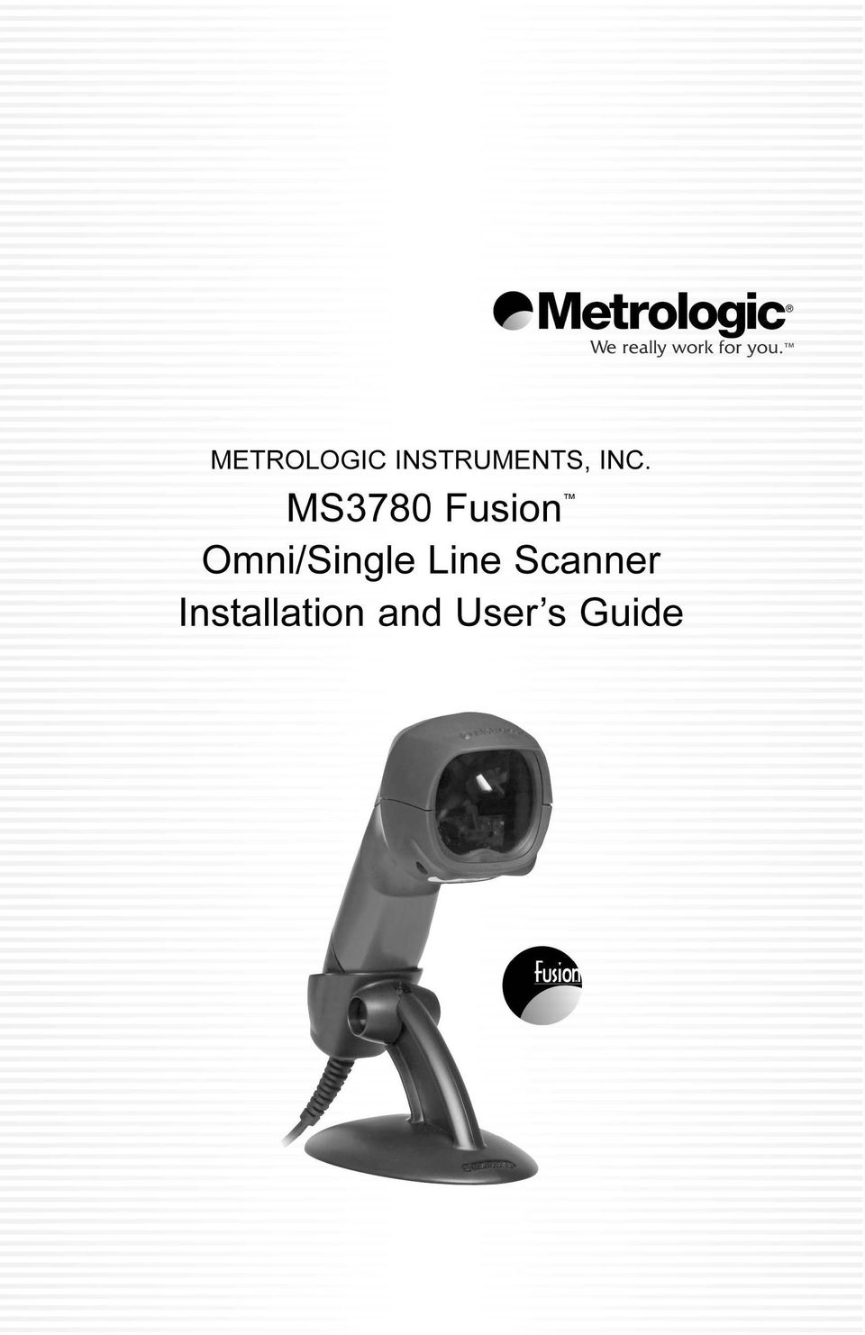
5 INTRODUCTION The Fusion is a hand-held, omnidirectional bar code scanner with optional single-line scanning capabilities. It utilizes the powerful Metrologic QuantumE scan engine to provide an outstanding scan performance on all standard 1D barcode symbologies, including RSS. Designed for retail applications, the Fusion includes additional key product features like: Fully Automatic Scanning Operation Single-Line Mode for Menu Reading Custom Configurable Scan Pattern User-Replaceable Single-Cable Interface to Host (PowerLink Compatible) User Configurable Depth of Field Easy Bar Code Configuration Data Editing 7 Beeper Tones Flash - Upgradeable Firmware OPOS and JPOS System Compatible CodeGate Sunrise 2005 Compliant SCANNER MS MS MS MS MS MS MS INTERFACE OCIA and RS232 Transmit/Receive IBM 46xx and Full RS232 RS232 Low Speed USB*, Keyboard Emulation Mode or USB Serial Emulation Mode Full Speed USB RS232/Light Pen Emulation Keyboard Wedge, Stand-Alone Keyboard and RS232 Transmit/Receive Stand Alone Keyboard and RS232 Transmit/Receive * Configurable for Keyboard Emulation Mode or Serial Emulation Mode. The default setting is Keyboard Emulation Mode. 1
 User Configurable Depth of Field Easy Bar Code Configuration Data Editing 7 Beeper Tones Flash - Upgradeable Firmware OPOS and")
6 INTRODUCTION Scanner and Accessories BASIC KIT COMPONENTS Part No. Description MS3780 Fusion Scanner MS3780 Installation and User s Guide * MetroSelect Configuration Guide * * Guides also available for download at OPTIONAL ACCESSORIES Part No. Description AC to DC Power Transformer - Regulated 650 ma output V United States and Canada V-240V Continental European V-240V United Kingdom V Australia V China The following cables are for Fusion models not equipped with EAS x x x-3 MVC-3MPC-IB9 MVC-3MNC-N7052 RS232 PowerLink Cable with Built in Power Jack 2.7 m (9 ft.) coiled cord, long strain relief, black Keyboard Wedge PowerLink cable with Adapter Cable 2.7 m (9 ft.) coiled cord, long strain relief, black Stand Alone Keyboard PowerLink Cable 2.7 m (9 ft.) coiled cord, long strain relief, black Metrologic Voltage Converter Cable, ±12VDC to +5.2VDC For IBM Applications Metrologic Voltage Converter Cable, ±12VDC to +5.2VDC For OCIA Applications Other items may be ordered for the specific protocol being used. To order additional items, contact the dealer, distributor or call Metrologic s customer service department at

7 INTRODUCTION Scanner and Accessories OPTIONAL ACCESSORIES Part No x-N x-N x-N-3 Description USB Full Speed Cable, Locking Plus-Power Type A 3 m (10 ft.) straight cord, short strain relief USB Full Speed Cable, Locking Plus-Power Type A 5 m (17 ft.) straight cord, short strain relief This cable is for use with full speed USB (-40) interface only. USB Low Speed Communication Cable, Type A (Non-Locking) Connector 2.8 m (9.2 ft.) straight cord, short strain relief The following cables are for Fusion models equipped with EAS x-E x-E-3 RS232 PowerLink Cable with Built in Power Jack and EAS Connection Wire (1 ft.) 1.8 m (6 ft.), long strain relief, straight cable, black IBM PowerLink Cable with Built in Power Jack and EAS Connection Wire (1 ft.) 1.8 m (6 ft.), long strain relief, straight, black Stand Other items may be ordered for the specific protocol being used. To order additional items, contact the dealer, distributor or call Metrologic s customer service department at
 1.8 m (6 ft.")
8 INTRODUCTION Scanner Components Figure 1. Scanner Components ITEM NO. DESCRIPTION 1 Red Output Window, Laser Aperture (See page 40) 2 Mode Select Button (See page 13) 3 Beeper (See page 15) 4 Blue LED, Single-Line Mode / Menu Reading (See page 15) 5 White LED (See page 15) 6 Blue LED, All Scan Lines On / Omnidirectional Reading (See page 15) 7 Amber LED, CodeGate (See page 15) 8 CodeGate Button (See page 14) 9 Pin Hole for Cable Release (See page 6) Pin RJ45, Female Socket (See page 36) 4
 7 Amber LED, CodeGate (See page 15) 8 CodeGate Button (See page 14) 9 Pin Hole for")
9 INTRODUCTION Caution and Serial Number Labels Stand Specifications Figure 2. Caution and Serial Labels Figure 3. Stand Specifications 5

10 Introduction Maintenance Smudges and dirt can interfere with the proper scanning of a bar code. Therefore, the output window will need occasional cleaning. 1. Spray glass cleaner onto a lint free, non-abrasive cleaning cloth. 2. Gently wipe the scanner window. Cable Removal Disconnect the power supply from the PowerLink cable and turn off power to the host system before removing the cable from the scanner. 1. Locate the small pin-hole beneath the Fusion logo on the front side of the scanner near the end of the handle. 2. Bend an ordinary paperclip into the shape shown above. 3. Insert the paperclip (or other small metallic pin) into the small pin-hole. There will be a faint click when the connector s lock releases. 4. Pull gently on the cable s strain-relief to remove the cable. Figure 4. Cable Connection Warning Important: If the PowerLink cable is not fully latched the unit can power intermittently. 6 Figure 5. Figure 6.

11 INSTALLATION RS232 or Light Pen 1. Turn off the host device. 2. Plug the male 10-pin RJ45 end of the PowerLink cable into the 10-pin socket on the MS Connect the 9-pin female end of the PowerLink cable to the appropriate communication port on the host device. 4. Plug the external power supply into the power jack on the PowerLink cable. Check the AC input requirements of the power supply to make sure the voltage matches the AC outlet. The outlet must be located near the equipment and be easily accessible. 5. Connect AC power to the transformer. 6. Turn on the host device. Figure 7. When the scanner first receives power the white LED will flash, one blue LED will turn on and the scanner will emit one beep. Plugging the scanner into the serial port of the PC does not guarantee that scanned information will appear at the PC. A software driver and correct configuration setting are also required for proper communication to occur. Caution To maintain compliance with applicable standards, all circuits connected to the scanner must meet the requirements for SELV (Safety Extra Low Voltage) according to EN/IEC To maintain compliance with standard CSA C22.2 No /UL and norm EN/IEC 60950, the power source should meet applicable performance requirements for a limited power source. 7

12 INSTALLATION IBM 46xx or OCIA 1. Turn off the host device. 2. Plug the male 10-pin RJ45 end of the MVC cable into the 10-pin socket on the MS For IBM: Connect the other end of the MVC cable to Port 9 of the host device. For OCIA: Connect the other end of the MVC cable to the appropriate communication port on the host device. 4. Turn on the host device. Figure 8. IBM (above), OCIA (below) When the scanner first receives power the white LED will flash, one blue LED will turn on and the scanner will emit one beep. Plugging the scanner into the serial port of the PC does not guarantee that scanned information will appear at the PC. A software driver and correct configuration setting are also required for proper communication to occur. Caution: To maintain compliance with applicable standards, all circuits connected to the scanner must meet the requirements for SELV (Safety Extra Low Voltage) according to EN/IEC To maintain compliance with standard CSA C22.2 No /UL and norm EN/IEC 60950, the power source should meet applicable performance requirements for a limited power source. 8

13 INSTALLATION Keyboard Wedge 1. Turn off the host device. 2. Plug the male 10-pin RJ45 end of the PowerLink cable into the 10-pin socket on the MS Disconnect the keyboard from the host device. 4. Connect the Y end of the PowerLink cable to the keyboard and the keyboard port on the host PC. If necessary use the male/female adapter cable supplied with the scanner for proper connections. 5. Plug the external power supply into the power jack on the PowerLink cable. Check the AC input requirements of the power supply to make sure the voltage matches the AC outlet. The outlet must be located near the equipment and be easily accessible. Figure Connect AC power to the transformer. 7. Turn on the host device. When the scanner first receives power the white LED will flash, one blue LED will turn on and the scanner will emit one beep. Powering the MS3780 directly from the host device can sometimes cause interference with the operation of the scanner or the computer. Not all computers supply the same current through the keyboard port. For this reason, Metrologic recommends using an external power supply. For additional information contact a Metrologic customer service representative. Caution: To maintain compliance with applicable standards, all circuits connected to the scanner must meet the requirements for SELV (Safety Extra Low Voltage) according to EN/IEC To maintain compliance with standard CSA C22.2 No /UL and norm EN/IEC 60950, the power source should meet applicable performance requirements for a limited power source. 9

14 INSTALLATION Stand-Alone Keyboard 1. Turn off the host device. 2. Plug the male 10-pin RJ45 end of the PowerLink cable into the 10-pin socket on the MS Connect the other end of the PowerLink cable to the keyboard port on the host device. 4. Plug the external power supply into the power jack on the PowerLink cable. Check the AC input requirements of the power supply to make sure the voltage matches the AC outlet. The outlet must be located near the equipment and be easily accessible. 5. Connect AC power to the transformer. 6. Turn on the host device. Figure 10. When the scanner first receives power the white LED will flash, one blue LED will turn on and the scanner will emit one beep. Powering the MS3780 directly from the host device can sometimes cause interference with the operation of the scanner or the computer. Not all computers supply the same current through the keyboard port. For this reason, Metrologic recommends using an external power supply. For additional information contact a Metrologic customer service representative. Caution: To maintain compliance with applicable standards, all circuits connected to the scanner must meet the requirements for SELV (Safety Extra Low Voltage) according to EN/IEC To maintain compliance with standard CSA C22.2 No /UL and norm EN/IEC 60950, the power source should meet applicable performance requirements for a limited power source. 10

15 INSTALLATION Full Speed or Low Speed USB (Integrated) 1. Turn off the host device. 2. Plug the male 10-pin RJ45 end of the USB PowerLink cable into the 10-pin socket on the MS Plug the other end of the USB interface cable into the host device s USB port. 4. Turn on the host device. Figure 11. As a default, the MS leaves the factory with USB Keyboard Emulation Mode enabled. For information on configuring the MS for USB Serial Emulation Mode, please refer to the USB: Low Speed section of the MetroSelect Configuration Guide (MLPN ). When the scanner first receives power the white LED will flash, one blue LED will turn on and the scanner will emit one beep. Plugging the scanner into the USB port of the PC does not guarantee that scanned information will appear at the PC. A software driver and correct configuration setting are also required for proper communication to occur. Caution: To maintain compliance with applicable standards, all circuits connected to the scanner must meet the requirements for SELV (Safety Extra Low Voltage) according to EN/IEC To maintain compliance with standard CSA C22.2 No /UL and norm EN/IEC 60950, the power source should meet applicable performance requirements for a limited power source. 11
.")
16 INSTALLATION EAS Deactivation EAS DEACTIVATION SW1 and SW2 are the switch banks inside the CheckPoint Device that set the deactivation range. The following is a list of CheckPoint recommended switch bank settings. CheckPoint Recommended Switch Bank Settings SW1 & SW2 switches 1 and 6 set to ON All Fusion models equipped with EAS capabilities have an EAS designation in their model numbers. The cable supplied with these units will have additional wires for connection to the CheckPoint Device. Figure 12. EAS Cable Connection (Bottom of StratosS) Figure 13 shows the location of the EAS deactivation area for Fusion. It is important to pass the entire tag through this area to deactivate the security tag. Figure 13. EAS Deactivation Area 12

17 SCANNER OPERATION The Scan Pattern Mode Select Button There are two configurable scan pattern modes available with the MS3780. The primary scan pattern mode is the default scan pattern active when the scanner starts. By default, the primary scan pattern is set to all-scan-lines for omnidirectional reading. Pressing the scan pattern mode button (see figure below) activates the secondary scan pattern mode. By default, the secondary scan pattern is set to single-line mode for menu reading. Please refer to the MetroSelect Configuration Guide for information on changing the default scan pattern settings. To Change Scan Pattern Modes 1. To activate the secondary scan pattern, press and release the mode select button. Press and Release the Mode Select Button Pattern Mode LED Switches to New Active Pattern Figure 14. Figure 15. Activating a pattern mode when the scanner is out of its stand does not change the in-stand pattern mode. When the scanner is returned to the stand it will automatically revert to the most recent scan pattern selected during in-stand operation. 2. To re-activate the primary scan pattern, press and release the mode select button again. 13

18 SCANNER OPERATION How to Use CodeGate and the Manual Activation Mode For illustration purposes the unit s scan pattern has been set to single-line (menu reading) mode. CODEGATE MANUAL ACTIVATION MODE* * This feature is not a default setting. Refer to the MetroSelect Configuration Guide for instructions on enabling the Manual Activation Mode. Figure 16. Figure 17. Factory Defaults: In-Stand, CodeGate is not active (Amber LED is On) Out-of-Stand, CodeGate is active (Amber LED is Off) For information on how to change the factory defaults, refer to the MetroSelect Configuration Guide ( ). 14
 Out-of-Stand, CodeGate is active (Amber LED is Off) For information on how to")
19 SCANNER OPERATION Audible Indicators When the MS3780 is in operation, it can provide audible feedback. These sounds indicate the status of the scanner. Eight settings are available for the tone of the beep (normal, 6 alternate tones and no tone). For instruction on how to change the tone of the beeper, refer to the MetroSelect Configuration Guide ( ). One Beep When the scanner first receives power; the white LED will flash, one blue LED will turn on and the scanner will emit a beep (the white LED will remain on for the duration of the beep). The scanner is now ready to scan. When the scanner successfully reads a bar code, the white LED will flash and the scanner will emit one beep (if configured to do so). If the scanner does not emit one beep and the white light does not flash, then the bar code has not been successfully read. Razzberry Tone This is a failure indicator. Refer to Failure Mode Indicators on page 17. Three Beeps - during operation When placing the scanner in configuration mode, the white and blue LEDs will flash while the scanner emits three beeps. The white and blue LEDs will continue to flash until the unit exits the configuration mode. Upon exiting the configuration mode, the scanner will emit three beeps and the white LED will stop flashing. When configured, 3 beeps can also indicate a communications timeout during normal scanning mode. When using one-code-programming, the scanner will emit three beeps: the current selected tone, followed by a short pause then a high tone and a low tone. This tells the user that the single code configuration has successfully configured the scanner. Three Beeps - on power up This is a failure indicator. Refer to Failure Mode Indicators on page
.")
20 SCANNER OPERATION Visual Indicators There are four LEDs located on the top of the MS3780. When the scanner is on, the flashing or constant illumination of the LEDs indicates the status of the current scan and the scanner. No LEDs 16 Figure 18. LED Indicators The LEDs will not be illuminated if the scanner is not receiving power from the host or transformer. They are also not illuminated when all lasers are turned off for any reason. Steady Blue Single-Line LED Indicates the laser is active and the scanner is in Single-Line Mode. The blue LED will remain illuminated until the laser is deactivated. Steady Blue Omni LED Indicates the laser is active and the scanner is in the Omnidirectionsl Mode. The blue LED will remain illuminated until the laser is deactivated. Steady Blue Single-Line or Omni LED and a Single White LED Flash When the scanner successfully reads a bar code, the white LED will flash and the scanner will beep once. If the white LED does not flash or the scanner does not beep, then the bar code has not been successfully read. Steady White and Blue Single-Line or Omni LED After a successful scan, the scanner transmits the data to the host device. Some communication modes require that the host inform the scanner when data is ready to be received. If the host is not ready to accept the information, the scanner s white LED will remain on until the data can be transmitted. Alternate Flashing of Both Blue LEDs and the White LED This indicates the scanner is in program mode. A razzberry tone indicates that an invalid bar code has been scanned in this mode. Steady Amber LED Indicates that CodeGate is not active (in-stand default).

21 SCANNER OPERATION Failure Mode Indicators Both Blue LEDs Flashing with One Emitted Razzberry Tone This indicates that the scanner has experienced a laser subsystem failure. Return the unit to a Metrologic authorized service center for repair. Both Blue LEDs and the White LED are Flashing with Two Emitted Razzberry Tones This indicates that the scanner has experienced a motor failure. Return the unit to a Metrologic authorized service center for repair. Continuous Razzberry Tone with Both LEDs Off - On Power Up A continuous razzberry tone upon power up indicates there has been an electronic failure. Return the unit to a Metrologic authorized service center for repair. Three Beeps - On Power Up This indicates that the nonvolatile memory that holds the scanner configuration has failed. Return the unit to a Metrologic authorized service center for repair. 17
22 SCANNER OPERATION Depth of Field Specifications* Normal Scan Zone Specifications are based on a 0.33 mm (13 mil) bar code. Figure 19. Normal Depth of Field * All specifications are subject to change without notice. 18
23 SCANNER OPERATION Depth of Field Specifications* Reduced Scan Zone Specifications are based on a 0.33 mm (13 mil) bar code. Figure 20. Reduced Depth of Field * All specifications are subject to change without notice. 19
24 SCANNER OPERATION Depth of Field by Bar Code Element Width* Normal Scan Zone MINIMUM BAR CODE ELEMENT WIDTH A B C D E F mm mils Figure 21. Normal Scan Zone by Bar Code Element Width * All specifications are subject to change without notice. 20
25 SCANNER OPERATION Depth of Field by Bar Code Element Width* Reduced Scan Zone MINIMUM BAR CODE ELEMENT WIDTH A B C D E F mm mils Figure 22. Reduced Scan Zone by Bar Code Element Width * All specifications are subject to change without notice. 21
26 SCANNER OPERATION IR Activation Range* Normal Reduced Figure 23. Normal IR Activation Range Figure 24. Reduced IR Activation Range * All specifications are subject to change without notice. 22
27 TROUBLESHOOTING GUIDE The following guide is for reference purposes only. Contact a Metrologic representative at ID-METRO or to preserve the limited warranty terms on page 42. Symptoms Possible Cause(s) Solution All Interfaces The unit has no LEDs, beeper or motor spin. The unit has no LEDs and / or beeper. There are multiple scans upon presentation of code. No power is being supplied to the scanner. No power is being supplied to the scanner from host. The same symbol timeout is set too short. Check the transformer, outlet and power strip. Make sure the cable is plugged into the scanner. Some host systems cannot supply enough current to power the MS3780. Use the power supply included with the scanner. Adjust the same symbol timeout for a longer time increment. The unit powers The beeper is disabled. Enable the beeper. up but does not beep. No tone is selected. Select a tone. The unit powers up but does not scan and/or beep. The unit is trying to scan a particular symbology that is not enabled. The scanner has been configured for a character length lock, or a minimum length and bar code being scanned does not satisfy the configured criteria. UPC/EAN, Code 39, Interleaved 2 of 5, Code 93, Code 128 and Codabar are enabled by default. Verify that the type of bar code being read has been selected Verify that the bar code that is being scanned falls into the criteria. Typical of Non-UPC/EAN codes. The scanner defaults to a minimum of 4 character bar code. 23
28 TROUBLESHOOTING GUIDE Symptoms Possible Cause(s) Solution All Interfaces The unit scans a bar code, but locks up after the first scan (the white LED stays on). The unit scans but the data transmitted to the host is incorrect. Scanner beeps at some bar codes and NOT for others of the same bar code symbology. The scanner is configured to support some form of host handshaking but is not receiving the signal. The scanner s data format does not match the host system requirements. The print quality of the bar code is suspect. The aspect ratio of the bar code is out of tolerance. The bar code may have been printed incorrectly. The scanner is not configured correctly for the type of bar code. The minimum symbol length setting does not work with the bar code. If the scanner is setup to support ACK/NAK, RTS/CTS, XON/XOFF or D/E, verify that the host cable and host are supporting the handshaking properly. Verify that the scanner s data format matches the format required by the host. Make sure that the scanner is connected to the proper host port. The type of printer and/or the printer settings could be the problem. Check the print mode or change the printer settings. For example, change to econo mode or high speed. Check if it is a check digit, character or border problem. Check if check digits are set properly. Check if the correct minimum symbol length is set. 24
29 TROUBLESHOOTING GUIDE Symptoms Possible Cause(s) Solution All Interfaces During power up the unit beeps 3 times. There is a non-volatile RAM failure. Contact a Metrologic service representative. During power up the unit razzes continuously. There is a RAM or ROM failure. Contact a Metrologic service representative. During power up the unit razzes once and the blue LED flashes. There is a VLD failure. Contact a Metrologic service representative. During power up the unit razzes twice and both LEDs flash. There is a scanner motor failure. Contact a Metrologic service representative. RS232 Only The unit powers up OK and scans OK but does not communicate properly to the host. The com port at the host is not working or is not configured properly. The cable is not connected to the proper com port. The com port is not operating properly. Check to make sure that the baud rate and parity of the scanner and the communication port match and that the program is looking for RS232 data. 25
30 TROUBLESHOOTING GUIDE Symptoms Possible Cause(s) Solution RS232 Only The host is receiving data but the data does not look correct. The scanner and host may not be configured for the same interface. Check that the scanner and the host are configured for the same interface. Characters are being dropped. The intercharacter delay needs to be added to the transmitted output. Add some intercharacter delay to the transmitted output by using the MetroSelect Configuration Guide (MLPN ). Keyboard Wedge Only The unit scans the bar code but there is no data. The unit scans but the data is not correct. The unit is not transmitting each character. Alpha characters show as lower case. Everything works except for a couple of characters. The unit may not be configured correctly. The unit may not be configured correctly. The unit may not be configured correctly. The computer is in caps lock mode. These characters may not be supported by the current country s key look up table. Make sure the scanner is configured for the appropriate mode. Make sure that the proper PC type (ie. AT, PS2 or XT) is selected. Verify correct country code and data formatting are selected. Adjust the intercharacter delay. Increase the interscan code delay setting. Adjust whether the F0 break is transmitted. It may be necessary to try both settings. Enable caps lock detect setting of the scanner to detect whether the PC is operating in caps lock. Try operating the scanner in Alt Mode. 26
31 DESIGN SPECIFICATIONS Operational Light Source: Laser Power: MS3780 Visible Laser Diode 650 nm 1.1 mw (Peak) Normal Depth of Field: 25 mm mm (1-11 ) Reduced Depth of Field: 25 mm mm (1-6 ) Omni Scan Single-Line Scan Speed: No. of Scan Lines: 20 Scan Speed: No. of Scan Lines: 1 Motor Speed: Min Bar Width: Decode Capability: 1333 scan lines per second 67 scan lines per second 4000 RPM mm (5.0 mil) All standard 1-D bar codes including RSS-14, RSS-Expanded, and RSS-14 Limited 0.33 mm (13 mil) bar code System Interfaces: Print Contrast: No. Characters Read: Beeper Operation: Indicators (LED): Termination: RS232, Keyboard Wedge, Stand-Alone Keyboard, Light Pen Emulation, IBM468x/469x, USB (low speed and full speed), OCIA 35% minimum reflectance difference Up to 80 data characters Maximum number will vary based on symbology and density. 7 tones or no beep Blue = laser on, ready to scan White = good read, decoding 10 position modular RJ45 connector Mechanical Cable: Application Dependent Scanner Length: 189 mm (7.44 ) Scanner Width: 65 mm (2.56 ) Scanner Height: 73 mm (2.88 ) Scanner Weight: 195 g (6.9 oz.) Specifications subject to change without notice. 27
32 DESIGN SPECIFICATIONS Electrical MS3780 Voltage Supply: 5VDC ± 0.25V Operating Power: Standby Power: Operating Current: Standby Current: DC Transformers: Laser Class 1: EMC: W 1.0 W 275 ma typical at 5VDC 200 ma typical at 5VDC Class II; 650 ma IEC :1993+A1:1997+A2:2001 EN :1994+A11:1996+A2:2001 FCC, ICES-003 & EN Class A Environmental Operating Temperature: Storage Temperature: Humidity: Contaminants: Ventilation: Shock: -20 C to 40 C (-4 F to 104 F) -40 C to 60 C (-40 F to 140 F) 5% to 95% relative humidity, non-condensing Sealed to resist airborne particulate contaminants None required Withstands multiple drops from 1.5 meters Specifications subject to change without notice. 28
33 APPLICATIONS AND PROTOCOLS The model number on each scanner includes the scanner number and factory default communications protocol. SCANNER VERSION INTERFACE IDENTIFIER 9 OCIA and RS232 Transmit/Receive 11 IBM 46xx and Full RS RS232 Low Speed USB*, Keyboard Emulation or USB Serial Emulation Mode MS Full Speed USB 41 RS232/Light Pen Emulation Keyboard Wedge, Stand-Alone Keyboard and RS232 Transmit/Receive Stand Alone Keyboard and RS232 Transmit/Receive The MS3780 scanner with Built-in PC Keyboard Wedge Interface is designed to be used for keyboard emulation only. Many RS232 configurable functions (e.g. formatting) available in other Metrologic scanners are also available as keyboard wedge functions. The following are the most important selectable options specific to the keyboard wedge. Keyboard Type ** AT (includes IBM PS2 models 50, 55, 60, 80) XT IBM PS2 (includes models 30, 70, 8556) Keyboard Country Type USA ** German Spanish Belgium Italian Swiss French Japan United Kingdom ** Default setting. For a complete list of default settings, see Default Settings - Communication Parameters starting on page 30 of this guide. Refer to the MetroSelect Configuration Guide (MLPN ) or MetroSet2 s help files for information on how to change the default settings. 29
34 DEFAULT SETTINGS - COMMUNICATION PARAMETERS Many functions of the scanner can be "configured" - that is enabled or disabled. The scanner is shipped from the factory configured to a set of default conditions. The default parameter of the scanner has an asterisk ( * ) in the charts on the following pages. If an asterisk is not in the default column then the default setting is off or disabled. Every interface does not support every parameter. If the interface supports a parameter listed in the charts on the following pages, a check mark ( ) will appear in the column for that interface. PARAMETER DEFAULT OCIA USB RS232* LIGHT PEN IBM 46XX KBW UPC/EAN * Code 128 * Code 93 * Codabar * Interleaved 2 of 5 (ITF) * MOD 10 Check on ITF Code 11 Code 39 * Full ASCII Code 39 MOD 43 Check on Code 39 MSI-Plessey MSI-Plessey 10/10 Check Digit MSI-Plessey MOD 10 Check Digit Paraf Support ITF Symbol Lengths Variable Minimum Symbol Length 4 Symbol Length Lock None RSS14 Enable RSS14 ID ]e0 * RSS14 App ID 01 * RSS14 Check Digit * RSS Expanded Enable 30
35 DEFAULT SETTINGS - COMMUNICATION PARAMETERS PARAMETER DEFAULT OCIA USB RS232* LIGHT PEN IBM 46XX KBW Expanded ID ]e0 * RSS Limited Enable RSS Limited ID ]e0 * RSS Limited App ID 01 * RSS Limited Check Digit * Bars High as Code 39 * Spaces High as Code 39 Bars High as Scanned Spaces High as Scanned DTS/SIEMENS DTS/NIXDORF * NCR F NCR S Poll Light Pen Source Beeper Tone Normal Beep/Transmit Sequence Before Transmit Communication Timeout None Razzberry Tone on Timeout Three Beeps on Timeout No Beeps on Timeout * Enter Power Save Mode 5 mins. Same Symbol Rescan Timeout: 500 msecs Programmable in 50 msec steps (MAX 6.35 seconds) * Intercharacter Delay Programmable in 1 msec steps (MAX 255 msecs) 1 msecs 10 msecs in KBW Number of Scan Buffers 1 31
36 DEFAULT SETTINGS - COMMUNICATION PARAMETERS PARAMETER DEFAULT OCIA USB RS232* LIGHT PEN IBM 46XX KBW Transmit UPC-A Check Digit * Transmit UPC-E Check Digit Expand UPC-E Convert UPC-A to EAN-13 Transmit Lead Zero on UPC-E Convert EAN-8 to EAN-13 Transmit UPC-A Number System * Transmit UPC-A Manufacturer ID# * Transmit UPC-A Item ID# * Transmit Codabar Start/Stop Characters CLSI Editing (Enable) Transmit Mod 43 Check Digit on Code 39 Transmit Code 39 Stop/Start Characters Transmit Mod 10/ITF Transmit MSI-Plessey Check Characters Parity Space Baud Rate Data Bits 7 Data Bits * Stop Bits 2 Transmit Sanyo ID Characters 32
37 DEFAULT SETTINGS - COMMUNICATION PARAMETERS PARAMETER DEFAULT OCIA USB RS232* LIGHT PEN IBM 46XX KBW Nixdorf ID LRC Enabled UPC Prefix UPC Suffix Transmit AIM ID Characters STX Prefix ETX Suffix Carriage Return * Line Feed - disabled by default in KBW * Tab Prefix Tab Suffix DE Disable Command FL Laser Enable Command DTR Handshaking Support RTS/CTS Handshaking Character RTS/CTS * Message RTS/CTS XON/XOFF Handshaking ACK/NAK Two Digit Supplements as code 39 Five Digit Supplements as code 39 Bookland as code (2 digit) Supplemental Requirement 33
38 DEFAULT SETTINGS - COMMUNICATION PARAMETERS PARAMETER DEFAULT OCIA USB RS232* LIGHT PEN IBM 46XX KBW Supplements are not Required * Two Digit Redundancy * Five Digit Redundancy 100 msec to Find Supplement Programmable in 100msec steps (MAX 800 msec) * Coupon Code 128 as code 39 Programmable Code Lengths Programmable Prefix Characters Programmable Suffix Characters Prefixes for individual Code Types 7 avail. 10 avail. 10 avail. Editing Inter Scan-Code Delay Programmable (100 µsec steps) 800 µsec Function/Control Key Support Minimum Element Width Programmable in 5.6 µsec steps 1 msec Normal Depth of Field * Reduced Depth of Field 34
39 UPGRADING THE FLASH ROM FIRMWARE The MetroSet2 program is a functional component of Metrologic s new line of Flash- based scanners. This program allows the user of a Metrologic scanner to quickly upgrade to a new or custom version of firmware. It requires the use of a personal computer running Windows 95 or greater and the use of a serial port. The user merely connects the scanner to a serial port on the PC, launches the MetroSet2 program, and blasts off to new software upgrades. Each MS3780, regardless of the version number or communication protocol, can be upgraded. In other words, all RS232 (-41), keyboard wedge (-47), light pen (-41), OCIA (-9), IBM 468X/469X (-11), low speed USB (-38), and integrated full speed USB (-40) units can be upgraded. To upgrade all units, a power supply and PowerLink cable (MLPN ) are required. RS232 units can be upgraded using the standard PowerLink cable (MLPN 53-53xxx-3). The program guides the user with its simplistic one click approach. The user must first select the file. Once the file is selected and verified, the scanner is ready to be upgraded. Press the Flash Scanner button to upgrade the scanner. The unit will go into a flash mode both the blue and white LEDs will be on. The user can follow the progress of the upgrade by watching the screen for details. When the upgrade is complete, the scanner will respond with its normal one beep on power up. If two beeps occur, the scanner did not upgrade properly. Contact a Metrologic service representative for additional assistance. 35
40 SCANNER AND CABLE TERMINATIONS Scanner Pinout Connections The MS3780 scanner interfaces terminate to a 10-pin modular socket. The serial # label indicates the interface enabled when the scanner is shipped from the factory. Keyboard Wedge and Stand-Alone Keyboard MS Figure 25. RS232 and Light Pen Emulation MS Pin Function Pin Function 1 Ground 1 Ground 2 RS232 Transmit Output 2 RS232 Transmit Output 3 RS232 Receive Input 3 RS232 Receive Input 4 PC Data 4 RTS Output 5 PC Clock 5 CTS Input 6 KB Clock 6 DTR Input/LTPN Source 7 PC +5V 7 Reserved 8 KB Data 8 LTPN Data 9 +5VDC 9 +5VDC 10 Shield Ground 10 Shield Ground MS Full Speed USB RS232 Low Speed USB MS Pin Function Pin Function 1 Ground/USB- 1 Ground/USB- 2 RS232 Transmit Output 2 RS232 Transmit Output 3 RS232 Receive Input 3 RS232 Receive Input 4 RTS Output 4 RTS Output 5 CTS Input 5 CTS Input 6 D+ 6 D+ 7 USB +V 7 USB +V 8 D- 8 D- 9 +5VDC 9 +5VDC 10 Shield Ground 10 Shield Ground Continued on next page. 36
41 SCANNER AND CABLE TERMINATIONS Figure 26. MS IBM 468X/469X MS OCIA Pin Function Pin Function 1 Ground 1 Ground 2 RS232 Transmit Output 2 RS232 Transmit Output 3 RS232 Receive Input 3 RS232 Receive Input 4 RTS Output 4 RDATA 5 CTS Input 5 RDATA Return 6 DTR Input 6 Clock In 7 IBM B-Transmit 7 Clock Out 8 IBM A+ Receive 8 Clock in Return/ Clock out Rtrn 9 +5VDC 9 +5VDC 10 Shield Ground 10 Shield Ground 37
42 SCANNER AND CABLE TERMINATIONS Cable Connector Configurations (Host End) Keyboard Wedge PowerLink Cable x-3 Pin Function 1 Keyboard Clock 2 Keyboard Data 3 No Connect 4 Power Ground 5 +5 Volts DC Pin Function 1 PC Data 2 No Connect 3 Power Ground 4 +5 Volts DC 5 PC Clock 6 No Connect 5-Pin DIN, Female 6-Pin DIN, Male Metrologic will supply an adapter cable with a 5-pin DIN male connector on one end and a 6-pin mini DIN female connector on the other. According to the termination required, connect the appropriate end of the adapter cable to the PowerLink cable, leaving the necessary termination exposed for connecting to the keyboard and the keyboard port on the PC. Keyboard Wedge Adapter Cable Pin Function 1 PC Clock 2 PC Data 3 No Connect 4 Power Ground 5 +5 Volts DC Pin Function 1 Keyboard Data 2 No Connect 3 Power Ground 4 +5 Volts DC 5 Keyboard Clock 6 No Connect 5-Pin DIN, Male 6-pin Mini DIN, Female 39
43 LASER AND PRODUCT SAFETY Caution Use of controls or adjustments or performance of procedures other than those specified herein may result in hazardous laser light exposure. Under no circumstances should the customer attempt to service the laser scanner. Never attempt to look at the laser beam, even if the scanner appears to be nonfunctional. Never open the scanner in an attempt to look into the device. Doing so could result in hazardous laser light exposure. The use of optical instruments with the laser equipment will increase eye hazard. Atención La modificación de los procedimientos, o la utilización de controles o ajustes distintos de los especificados aquí, pueden provocar una luz de láser peligrosa. Bajo ninguna circunstancia el usuario deberá realizar el mantenimiento del láser del escáner. Ni intentar mirar al haz del láser incluso cuando este no esté operativo. Tampoco deberá abrir el escáner para examinar el aparato. El hacerlo puede conllevar una exposición peligrosa a la luz de láser. El uso de instrumentos ópticos con el equipo láser puede incrementar el riesgo para la vista. Attention L'emploi de commandes, réglages ou procédés autres que ceux décrits ici peut entraîner de graves irradiations. Le client ne doit en aucun cas essayer d'entretenir lui-même le scanner ou le laser. Ne regardez jamais directement le rayon laser, même si vous croyez que le scanner est inactif. N'ouvrez jamais le scanner pour regarder dans l'appareil. Ce faisant, vous vous exposez à une rayonnement laser qú êst hazardous. L'emploi d'appareils optiques avec cet équipement laser augmente le risque d'endommagement de la vision. Achtung Die Verwendung anderer als der hier beschriebenen Steuerungen, Einstellungen oder Verfahren kann eine gefährliche Laserstrahlung hervorrufen. Der Kunde sollte unter keinen Umständen versuchen, den Laser-Scanner selbst zu warten. Sehen Sie niemals in den Laserstrahl, selbst wenn Sie glauben, daß der Scanner nicht aktiv ist. Öffnen Sie niemals den Scanner, um in das Gerät hineinzusehen. Wenn Sie dies tun, können Sie sich einer gefährlichen Laserstrahlung aussetzen. Der Einsatz optischer Geräte mit dieser Laserausrüstung erhöht das Risiko einer Sehschädigung. Attenzione L utilizzo di sistemi di controllo, di regolazioni o di procedimenti diversi da quelli descritti nel presente Manuale può provocare delle esposizioni a raggi laser rischiose. Il cliente non deve assolutamente tentare di riparare egli stesso lo scanner laser. Non guardate mai il raggio laser, anche se credete che lo scanner non sia attivo. Non aprite mai lo scanner per guardare dentro l apparecchio. Facendolo potete esporvi ad una esposizione laser rischiosa. L uso di apparecchi ottici, equipaggiati con raggi laser, aumenta il rischio di danni alla vista. 40
44 LASER AND PRODUCT SAFETY Notices This equipment has been tested and found to comply with limits for a Class A digital device, pursuant to part 15 of the FCC Rules. These limits are designed to provide reasonable protection against harmful interference when the equipment is operated in a commercial environment. This equipment generates, uses and can radiate radio frequency energy and, if not installed and used in accordance with the instruction manual, may cause harmful interference to radio communications. Operation of this equipment in a residential area is likely to cause harmful interference, in which case the user will be required to correct the interference at their own expense. Any unauthorized changes or modifications to this equipment could void the user s authority to operate this device. This device complies with part 15 of the FCC Rules. Operation is subject to the following two conditions: (1) This device may not cause harmful interference, and (2) this device must accept any interference received, including interference that may cause undesired operation. Notice This Class A digital apparatus complies with Canadian ICES-003. Remarque Cet appareil numérique de la classe A, conformé a la norme NMB-003 du Canada. European Standard Warning This is a class A product. In a domestic environment this product may cause radio interference in which case the user may be required to take adequate measures. Funkstöreigenschaften nach EN 55022:1998 Warnung! Dies ist eine Einrichtung der Klasse A. Diese Einrichtung kann im Wohnbereich Funkstörungen verursachen; in diesem fall kann vom Betrieber verlangt werden, angemessene Maßnahmen durchführen. Standard Europeo Attenzione Questo e un prodotto di classe A. Se usato in vicinanza di residenze private potrebbe causare interferenze radio che potrebbero richiedere all utilizzatore opportune misure. Attention Ce produit est de classe A. Dans un environnement domestique, ce produit peut être la cause d interférences radio. Dans ce cas l utiliseteur peut être amené à predre les mesures adéquates. 41
45 SCANNER AND CABLE TERMINATIONS Cable Connector Configurations (Host End) RS232 PowerLink Cable Pin Function 1 Shield Ground 2 RS232 Transmit Output RS232 Receive Input 4 DTR Input/Light Pen Source 5 Power/Signal Ground 6 Light Pen Data 7 CTS Input 8 RTS Output 9-Pin D-Type Connector VDC USB Power/Communication Cable x-N-3, x-N-3 or x-N-3 Pin Function 1 PC +5V/V_USB 2 D- 3 D+ 4 Ground Shield Shield USB Type A Locking with Power USB Non-Locking Stand Alone Keyboard PowerLink Cable x-3 Pin 1 PC Data 2 No Connect 3 Power Ground Function 4 +5VDC PC Power to KB 5 PC Clock 6 No Connect 6-Pin Male Mini-DIN Connector 38
46 LIMITED WARRANTY The MS3780 Fusion scanners are manufactured by Metrologic at its Blackwood, New Jersey, U.S.A. facility. The MS3780 Fusion scanners have a five (5) year limited warranty from the date of manufacture. Metrologic warrants and represents that all MS3780 Fusion scanners are free of all defects in material, workmanship and design, and have been produced and labeled in compliance with all applicable U.S. Federal, state and local laws, regulations and ordinances pertaining to their production and labeling. This warranty is limited to repair, replacement of product or refund of product price at the sole discretion of Metrologic. Faulty equipment must be returned to one of the following Metrologic repair facilities: Blackwood, New Jersey, USA; Madrid, Spain; or Suzhou, China. To do this, contact the appropriate Metrologic Customer Service/Repair Department to obtain a Returned Material Authorization (RMA) number. In the event that it is determined the equipment failure is covered under this warranty, Metrologic shall, at its sole option, repair the Product or replace the Product with a functionally equivalent unit and return such repaired or replaced Product without charge for service or return freight, whether distributor, dealer/reseller, or retail consumer, or refund an amount equal to the original purchase price. This limited warranty does not extend to any Product which, in the sole judgment of Metrologic, has been subjected to abuse, misuse, neglect, improper installation, or accident, nor any damage due to use or misuse produced from integration of the Product into any mechanical, electrical or computer system. The warranty is void if the case of Product is opened by anyone other than Metrologic s repair department or authorized repair centers. THIS LIMITED WARRANTY, EXCEPT AS TO TITLE, IS IN LIEU OF ALL OTHER WARRANTIES OR GUARANTEES, EITHER EXPRESS OR IMPLIED, AND SPECIFICALLY EXCLUDES, WITHOUT LIMITATION, WARRANTIES OF MERCHANTABILITY AND FITNESS FOR A PARTICULAR PURPOSE UNDER THE UNIFORM COMMERCIAL CODE, OR ARISING OUT OF CUSTOM OR CONDUCT. THE RIGHTS AND REMEDIES PROVIDED HEREIN ARE EXCLUSIVE AND IN LIEU OF ANY OTHER RIGHTS OR REMEDIES. IN NO EVENT SHALL METROLOGIC BE LIABLE FOR ANY INDIRECT OR CONSEQUENTIAL DAMAGES, INCIDENTAL DAMAGES, DAMAGES TO PERSON OR PROPERTY, OR EFFECT ON BUSINESS OR PROPERTY, OR OTHER DAMAGES OR EXPENSES DUE DIRECTLY OR INDIRECTLY TO THE PRODUCT, EXCEPT AS STATED IN THIS WARRANTY. IN NO EVENT SHALL ANY LIABILITY OF METROLOGIC EXCEED THE ACTUAL AMOUNT PAID TO METROLOGIC FOR THE PRODUCT. METROLOGIC RESERVES THE RIGHT TO MAKE ANY CHANGES TO THE PRODUCT DESCRIBED HEREIN. WORLDWIDE HEADQUARTERS, METROLOGIC THE AMERICAS HEADQUARTERS Metrologic Instruments, Inc. METROLOGIC THE AMERICAS 90 Coles Rd Imperial Way Suite B Blackwood, NJ West Deptford, NJ Tel: Tel: 800-ID-METRO ( ) Fax: Fax: info@metrologic.com info@us.metrologic.com MTLG AUTO ID INSTRUMENTS (SHANGHAI) CO., LTD METROLOGIC EUROPEAN REPAIR CENTER (MERC) Suzhou Sales Office Metrologic Eria Ibérica, SL BLK A, Room# 03/03-04 Julian Camarillo 29, D-1 No.5 Xinghan Street, Xinsu Industrial Square Madrid China-Singapore Tel: Suahou Industrial Park, Suzhou, PRC Fax: Tel: info@es.metrologic.com Fax: info@cn.metrologic.com 42
47 PATENTS Patent Information This METROLOGIC product may be covered by one or more of the following U.S. Patents: U.S. Patent No.; 5,216,232; 5,260,553; 5,340,971; 5,340,973; 5,424,525; 5,468,951; 5,484,992; 5,525,789; 5,528,024; 5,557,093; 5,591,953; 5,616,908; 5,627,359; 5,637,852; 5,661,292; 5,767,501; 5,777,315; 5,789,730; 5,789,731; 5,796,091; 5,811,780; 5,825,012; 5,828,048; 5,844,227; 5,883,375; 5,886,337; 5,895,907; 5,925,870; 5,925,871; 5,939,698; 5,942,743; 6,029,894; 6,098,885; 6,182,898; 6,189,793; 6,286,760; 6,299,067; 6,347,743; 6,412,696; 6,460,767; 6,604,684; 6,856,572; 6,905,071; 6,209,789; 6,860,427 No license right or sublicense is granted, either expressly or by implication, estoppel, or otherwise, under any METROLOGIC or third party intellectual property rights (whether or not such third party rights are licensed to METROLOGIC), including any third party patent listed above, except for an implied license only for the normal intended use of the specific equipment, circuits, and devices represented by or contained in the METROLOGIC products that are physically transferred to the user, and only to the extent of METROLOGIC S license rights and subject to any conditions, covenants and restrictions therein. Other worldwide patents pending. 43
48 INDEX A AC...2, 7 11 Accessories...2, 3 Adapter...9 Audible Indicator , 23 26, 35 B Bar Code , 23 26, 27 Bar Width...27 Beep... 15, 16, 17, 23 26, 35 Blue LED , 23 26, 35 Button...4, CodeGate...4 Mode Select...4 C Cable Communication...2, 7 11, 23 26, 35, EAS...12 IBM...2 Keyboard Wedge...2, OCIA...2 Pin Assignments PowerLink.. 2, 6, 7 11, 35, RS Troubleshooting USB Caution...5, 7 11, 40 Class...41 CodeGate...1, 4, Communication...16, 23 26, 29 Parameters Compliance Components...2, 4 Configuration...15, 17 Default Current...28 D DC...2, 28 Default Settings...13, 29, Depth of Field Normal...18, 20, 27, 34 Reduced... 19, 20, 21, 27, 34 E EAS F Failure Modes FCC Firmware Flash ROM... 1, 35 H Host I IBM... 8, Indicator Audible.. 4, 15 17, 23 26, 27, 35 Failure Visual... 4, 15 17, 23 26, 27, 35 Interface IBM... 1, 8, Keyboard Wedge. 1, 9, 26, Laser Emulation... 1, Light Pen... 1, 7, OCIA... 1, 8, RS , 7, 25, 26, Stand-Alone Keyboard... 1, 10 Troubleshooting USB... 1, 11, IR Activation Range Far Near K Keyboard Keyboard Wedge... 9, 26, L Label Caution... 5 Serial Number... 5 Laser... 4, 40 Laser Emulation LED Light Pen... 7,
49 INDEX Light Source...27 M Maintenance...6 Manual...2, 15, 29 MetroSet Mode of Operation Button...14 Primary Secondary Mode Select...4 Motor Speed...27 Mounting Specifications...5 N Notices...41 O OCIA...8, Omnidirectional Mode...4 Operation...41 P Patents...43 Pin Assignments Cable Scanner Port , Power...2, 7 11, 35 Power Supply...6 PowerLink Product Safety...40 Protocol...29 R RAM...25 Razzberry Tone , 25 Read Rate...14 Repair...17 ROM...25 RS , 25, 26, S Scan Lines Scan Pattern... 1, 27 Primary Secondary Single-Line Scan Speed SELV Single-Line Mode... 4 Specification Electrical Environmental Mechanical Operational Stand-Alone Keyboard Storage Switch Bank T Tone... 1, 15 Transformer... 2, 28 Troubleshooting U Upgrade USB... 11, V Ventilation Visual Indicator , 23 26, 35 Blue LED... 4, White LED... 4, Amber LED... 4, Voltage , 28 Volume W Weight White LED , 23 26, 35 Window
METROLOGIC INSTRUMENTS, INC. MS1690 Focus Area Imaging Bar Code Scanner Installation and User s Guide
 METROLOGIC INSTRUMENTS, INC. MS1690 Focus Area Imaging Bar Code Scanner Installation and User s Guide Copyright 2005 by Metrologic Instruments, Inc. All rights reserved. No part of this work may be reproduced,
METROLOGIC INSTRUMENTS, INC. MS3580 QuantumT Installation and User's Guide
 METROLOGIC INSTRUMENTS, INC. MS3580 QuantumT Installation and User's Guide Copyright 2005 by Metrologic Instruments, Inc. All rights reserved. No part of this work may be reproduced, transmitted, or stored
Laser Barcode Scanner
 Laser Barcode Scanner User s Manual FCC Compliance This equipment has been tested and found to comply with the limits for a Class A digital device, pursuant to Part 15 of the FCC Rules. These limits are
METROLOGIC INSTRUMENTS, INC. MS1690 Focus Area Imaging Bar Code Scanner Installation and User s Guide
 METROLOGIC INSTRUMENTS, INC. MS1690 Focus Area Imaging Bar Code Scanner Installation and User s Guide Copyright 2005 by Metrologic Instruments, Inc. All rights reserved. No part of this work may be reproduced,
METROLOGIC INSTRUMENTS, INC. IS6520/MS6520 Cubit Series Omnidirectional Bar Code Scanner Installation and User s Guide
 METROLOGIC INSTRUMENTS, INC. IS6520/MS6520 Cubit Series Omnidirectional Bar Code Scanner Installation and User s Guide LOCATIONS Corporate Headquarters North America Metrologic Instruments, Inc. Customer
MS9500 SERIES VOYAGER PRODUCT GUIDE. Single Line, Hand-Held, 1D, High-Density 1D, PDF-417 2D and Wireless Laser Bar Code Scanners
 MS9500 SERIES VOYAGER PRODUCT GUIDE Single Line, Hand-Held, 1D, High-Density 1D, PDF-417 2D and Wireless Laser Bar Code Scanners Contents About Voyager Scanners Voyager Selection Chart MS9520 Voyager MS9540
Laser Barcode Scanner User s Manual
 Laser Barcode Scanner User s Manual FCC Compliance This equipment has been tested and found to comply with the limits for a Class A digital device, pursuant to Part 15 of the FCC Rules. These limits are
METROLOGIC INSTRUMENTS, INC. IS1650 FocusE Area Imaging Bar Code Scanner Installation and User s Guide
 METROLOGIC INSTRUMENTS, INC. IS1650 FocusE Area Imaging Bar Code Scanner Installation and User s Guide Copyright 2008 by Metrologic Instruments, Inc. All rights reserved. No part of this work may be reproduced,
QuantumT 3580. Omnidirectional Laser Scanner. User s Guide
 QuantumT 3580 Omnidirectional Laser Scanner User s Guide Disclaimer Honeywell International Inc. ( HII ) reserves the right to make changes in specifications and other information contained in this document
E-i. Section E. Code Formatting. E/D = Enable/Disable T/DNT = Transmit/Do Not Transmit EX/DNEX = Expand/Do Not Expand
 Section E Code Formatting E/D = Enable/Disable T/DNT = Transmit/Do Not Transmit EX/DNEX = Expand/Do Not Expand C/DNC = Convert/Do Not Convert E/DNE = Enable/Do Not Enable T/DNT UPC-A Check Digit (E - 1)
METROLOGIC INSTRUMENTS, INC. MetroSelect Configuration Guide
 METROLOGIC INSTRUMENTS, INC. MetroSelect Configuration Guide Copyright 2005 by Metrologic Instruments, Inc. All rights reserved. No part of this work may be reproduced, transmitted, or stored in any form
QUICK START GUIDE. Wasp WLS 9500. www.waspbarcode.com
 QUICK START GUIDE Wasp WLS 9500 www.waspbarcode.com LED Scan Window Beeper Trigger CORD ATTACHMENT Model Number and Serial Number appear here. Cable interface Interface cable modular connector Interface
METROLOGIC INSTRUMENTS, INC. MS9590 VoyagerGS Single-Line Hand Held Laser Scanner Installation and User's Guide
 METROLOGIC INSTRUMENTS, INC. MS9590 VoyagerGS Single-Line Hand Held Laser Scanner Installation and User's Guide Copyright 2007 by Metrologic Instruments, Inc. All rights reserved. No part of this work
VoyagerGS 9590 Series
 VoyagerGS 9590 Series Single-Line Hand Held Laser Scanner User's Guide Disclaimer Honeywell International Inc. ( HII ) reserves the right to make changes in specifications and other information contained
METROLOGIC INSTRUMENTS INC. MetroSelect Single-Line Configuration Guide
 METROLOGIC INSTRUMENTS INC. MetroSelect Single-Line Configuration Guide Copyright 2005 by Metrologic Instruments, Inc. All rights reserved. No part of this work may be reproduced, transmitted, or stored
Wireless Laser Barcode Scanner ils 6300BU. User s Manual
 Wireless Laser Barcode Scanner ils 6300BU User s Manual FCC Compliance This equipment has been tested and found to comply with the limits for a Class A digital device, pursuant to Part 15 of the FCC Rules.
MetroSelect Programming Guide. MLPN 2407/December 1998
 MetroSelect Programming Guide MLPN 2407/December 1998 Locations: USA Corporate Headquarters Europe Metrologic Instruments, Inc. Metrologic Instruments GmbH 90 Coles Road Dornierstrasse 2 Blackwood, NJ
USER'S GUIDE NUSCAN 2100 Series
 BARCODE SCANNER USER'S GUIDE NUSCAN 2100 Series Table of Contents 1. Limited Warranty...1 2. Introduction...2 3. Contents...3 4. Barcode Symbologies...3 5. Product Introduction...3 6. Installation...4
7820 Solaris. Bar Code Scanner. User s Guide
 7820 Solaris Bar Code Scanner User s Guide Disclaimer Honeywell International Inc. ( HII ) reserves the right to make changes in specifications and other information contained in this document without
7820 Solaris. Bar Code Scanner. User s Guide
 7820 Solaris Bar Code Scanner User s Guide Disclaimer Honeywell International Inc. ( HII ) reserves the right to make changes in specifications and other information contained in this document without
BCST-20 Barcode Scanner. Instruction Manual. www.inateck.com
 BCST-20 Barcode Scanner Instruction Manual www.inateck.com IMPORTANT NOTICE Safety Precaution * DO NOT disassemble the scanner, or place foreign matter into the scanner causing a short circuit or circuit
MetroSelect. Single-Line Scanner. Configuration Guide
 MetroSelect Single-Line Scanner Configuration Guide Disclaimer Honeywell International Inc. ( HII ) reserves the right to make changes in specifications and other information contained in this document
Voyager 9520/40 Voyager GS9590 Eclipse 5145
 Voyager 9520/40 Voyager GS9590 Eclipse 5145 Quick Start Guide Aller à www.honeywellaidc.com pour le français. Vai a www.honeywellaidc.com per l'italiano. Gehe zu www.honeywellaidc.com für Deutsch. Ir a
Symbol LS9203. Product Reference Guide
 Symbol LS9203 Product Reference Guide Symbol LS9203 Product Reference Guide 72E-71538-03 Revision A February 2007 Motorola, Inc. 2007. All rights reserved. No part of this publication may be reproduced
Gateway Port Replicator User Guide
 Gateway Port Replicator User Guide Using the Port Replicator Identifying features Connecting and disconnecting the port replicator 1 Using the Port Replicator Top Power button Component Icon Description
Bluetooth Version FUZZYSCAN FAMILY. Quick Start Guide WIRELESS SCANNER
 Bluetooth Version FUZZYSCAN FAMILY Quick Start Guide WIRELESS SCANNER Getting Familiar with Your FuzzyScan Thank you for choosing Cino FuzzyScan Bluetooth Cordless Image Scanner. Powered by the combination
Bar Code CCD Scanner OPERATION MANUAL
 ISO 9002 Certified Lead with technology Win customers with service Bar Code CCD Scanner OPERATION MANUAL 69 Jarltech International Inc. 1998. All rights reserved. Under the copyright laws, this manual
MS2xxx SERIES Stratos PRODUCT GUIDE
 Metrologic Instruments, Inc. is a global supplier of choice for data capture and collection hardware, optical solutions, and image processing software. Metrologic has been delivering innovative, quality
HANDHELD LASER SCANNER
 HANDHELD LASER SCANNER PROGRAMMING GUIDE PSC Scanning, Inc. En Suisse: 959 Terry Street GOMARO s.a. Eugene, Oregon 97402-9120 1123 Aclens - Switzerland Telephone: (541) 683-5700 http://www.gomaro.ch/ Toll
Metrologic MS1690 2D Scanner Installation Guide
 Metrologic MS1690 2D Scanner Installation Guide Revision 1.0 Revision History 1.0 04/17/2007 Initial Release The latest version of this document can be found in the following places: Internally for Cerner
METROLOGIC INSTRUMENTS, INC. IS4225 ScanGlove USB Addendum for the MetroSelect Single-Line Configuration Guide
 METROLOGIC INSTRUMENTS, INC. IS4225 ScanGlove USB Addendum for the MetroSelect Single-Line Configuration Guide Copyright 2005 by Metrologic Instruments, Inc. All rights reserved. No part of this work may
HS-251xW-TS Series Laser Barcode Scanner User s Manual
 HS-251xW-TS Series Laser Barcode Scanner User s Manual FCC Notes: This equipment generates, uses, and can radiate radio frequency energy and, if not installed and used in accordance with the instructions
VersaScan II. Barcode Scanner Quick Start Manual. ID TECH 10721 Walker Street Cypress, CA 90630 (714) 761-6368 www.idtechproducts.
 761-6368 www.idtechproducts.") VersaScan II TM Barcode Scanner Quick Start Manual ID TECH 10721 Walker Street Cypress, CA 90630 (714) 761-6368 www.idtechproducts.com 80105501-001 rev.a FCC WARNING STATEMENT This equipment has been tested
VersaScan II TM Barcode Scanner Quick Start Manual ID TECH 10721 Walker Street Cypress, CA 90630 (714) 761-6368 www.idtechproducts.com 80105501-001 rev.a FCC WARNING STATEMENT This equipment has been tested
Copyright. Trademarks
 Copyright 2007 by Metrologic Instruments, Inc. All rights reserved. No part of this work may be reproduced, transmitted, or stored in any form or by any means without prior written consent, except by reviewer,
IMATION SECURE SCAN. ck Start Guide. Imation Secure Scan
 IMATION SECURE SCAN Quick ck Start Guide Imation Corp 2012 Imation Secure Scan page 1 of 6 1 Unpacking your Imation Secure Scan The following items are contained inside the case: 1 2 Imation Secure Scan
MetroSelect Single Line Configuration Guide. MS9500 Voyager Series i
 MetroSelect Single Line Configuration Guide MS9500 Voyager Series i LOCATIONS Corporate Headquarters Metrologic Instruments, Inc. Customer Service: 1-800-ID-METRO 90 Coles Road Tel: 856-228-8100 Blackwood,
DUET / VS800 Scanner. DUET Scanner VS800 Scanner. Programming Kit
 DUET / VS800 Scanner DUET Scanner VS800 Scanner Programming Kit PSC Scanning, Inc. 959 Terry Street Eugene, Oregon 97402 Telephone: (541) 683-5700 Telefax: (541) 345-7140 PSC and the PSC logo are registered
METROLOGIC INSTRUMENTS, INC. MS7320 InVista Series Installation and User s Guide
 METROLOGIC INSTRUMENTS, INC. MS7320 InVista Series Installation and User s Guide LOCATIONS CORPORATE HEADQUARTERS North America Metrologic Instruments, Inc. Customer Service: 1-800-ID-METRO 90 Coles Road
BARCODE READER V 2.1 EN USER MANUAL
 BARCODE READER V 2.1 EN USER MANUAL INSTALLATION OF YOUR DEVICE PS-2 Connection RS-232 Connection (need 5Volts power supply) 1 INSTALLATION OF YOUR DEVICE USB Connection 2 USING THIS MANUAL TO SETUP YOUR
ENGLISH FRANÇAIS DEUTSCH ESPAÑOL ÐÓÑÑÊÈÉ
 ÐÓÑÑÊÈÉ ESPAÑOL DEUTSCH FRANÇAIS ENGLISH ÐÓÑÑÊÈÉ ESPAÑOL DEUTSCH FRANÇAIS ENGLISH ÐÓÑÑÊÈÉ ESPAÑOL DEUTSCH FRANÇAIS ENGLISH ÐÓÑÑÊÈÉ ESPAÑOL DEUTSCH FRANÇAIS ENGLISH ÐÓÑÑÊÈÉ ESPAÑOL DEUTSCH FRANÇAIS ENGLISH
Laser Scanner Programming Guide (SE923 laser engine)
") Laser Scanner Programming Guide (SE923 laser engine) CONTENT Technical note... 5 How to recognise the type of the laser barcode engine... 5 How to program the laser barcode reader into default value...
Laser Scanner Programming Guide (SE923 laser engine) CONTENT Technical note... 5 How to recognise the type of the laser barcode engine... 5 How to program the laser barcode reader into default value...
TMCT-10 Barcode Scanner User Manual. 102, 5661-99 St. Edmonton, AB T6E 3N8 Ph. 780.988.0215 Fax 780.988.0465
 TMCT-10 Barcode Scanner User Manual 102, 5661-99 St. Edmonton, AB T6E 3N8 Ph. 780.988.0215 Fax 780.988.0465 IMPORTANT NOTICE Safety Precaution * DO NOT disassemble the scanner, or place foreign matter
MS9500 Voyager Series Single-Line Hand-Held Laser Scanner Installation and User s Guide
 MS9500 Voyager Series Single-Line Hand-Held Laser Scanner Installation and User s Guide Locations USA Corporate Headquarters Europe Metrologic Instruments, Inc. Metrologic Instruments GmbH 90 Coles Road
METROLOGIC INSTRUMENTS, INC. MS6720 Hand-Held Laser Scanner Installation and User s Guide
 METROLOGIC INSTRUMENTS, INC. MS6720 Hand-Held Laser Scanner Installation and User s Guide LOCATIONS CORPORATE HEADQUARTERS NORTH AMERICA EUROPEAN, MIDDLE EAST & AFRICAN HEADQUARTERS USA, NEW JERSEY GERMANY,
Professional USB to Serial Adapter Hub with COM Retention
 Professional USB to Serial Adapter Hub with COM Retention ICUSB2321X ICUSB2322X ICUSB2324X *actual product may vary from photos *actual product may vary from photos DE: Bedienungsanleitung - de.startech.com
BroadBand PowerShield. User Manual
 BroadBand PowerShield User Manual 990-0375G 12/2006 Chapter 1 General Information The PowerShield provides a power source for broadband telephony and other DC applications. Safety This Safety Guide contains
DMX USB PRO. User Manual. www.enttec.com
 DMX USB PRO User Manual www.enttec.com Firmware V1.43 February 2007 Package Contents Your DMX USB PRO package should contain these items: DMX USB PRO (Part No. 70304) Driver for Windows software on the
Technical Manual. For use with Caller ID signaling types: Belcore 202, British Telecom, & ETSI
 Technical Manual For use with Caller ID signaling types: Belcore 202, British Telecom, & ETSI Caller ID.com WHOZZ CALLING? POS 2 Caller ID Monitoring Unit Technical Manual For use with Caller ID signaling
METROLOGIC INSTRUMENTS, INC. Area Imaging Bar Code Supplemental Configuration Guide
 METROLOGIC INSTRUMENTS, INC. Area Imaging Bar Code Supplemental Configuration Guide Copyright 2007 by Metrologic Instruments, Inc. All rights reserved. No part of this work may be reproduced, transmitted,
Quick Installation. A Series of Intelligent Bar Code Reader with NeuroFuzzy Decoding. Quick Installation
 Quick Installation A Series of Intelligent Bar Code Reader with NeuroFuzzy Decoding This chapter intends to get your new FuzzyScan scanner working with your existing system within minutes. General instructions
3800 Linear Series. Quick Start Guide
 3800 Linear Series Quick Start Guide Note: Refer to your user s guide for information about cleaning your device. For localized language versions of this document, go to www.honeywell.com/aidc. Getting
READ FIRST! Universal Car/Air Adapter User Manual
 AutoAir Manual 1/9/03 2:03 PM Page 1 READ FIRST! Universal Car/Air Adapter User Manual Congratulations! Your new Kensington Universal Car/Air Adapter is a highly efficient Universal Car/Air Adapter for
Aquadyne TechTip TITLE: TROUBLESHOOTING PC COM PORT AND MODEM PRODUCTS AFFECTED SYMPTOMS POSSIBLE CAUSES
 Aquadyne TechTip TITLE: TROUBLESHOOTING PC COM PORT AND MODEM COMMUNICATIONS WITH AN OCTOPUS. Article # 072297-1 Last reviewed: 03/25/98 Keywords: Serial Port, Modem, Polling, AquaWeb, Node Not Responding
Barcode Scanning Made Easy. Programming Guide
 Barcode Scanning Made Easy Programming Guide CCD Scanner Programming Guide Please Read Note: The Wasp WCS3900 Series Scanners are ready to scan the most popular barcodes out of the box. This manual should
Intelli-Time Alarm Clock model 13027
 Instruction Manual Intelli-Time Alarm Clock model 13027 CONTENTS Unpacking Instructions... 2 Package Contents... 2 Product Registration... 2 Features & Benefits... 3 Clock Setup... 4 Intelli-Time Clock...
ENGLISH USER S MANUAL. compact handheld 1D/2D code scanner
 ENGLISH USER S MANUAL compact handheld 1D/D code scanner 11175-en-GB 5J006 04 006 1 3 A B 4 C INSTALLATION INSTRUCTIONS FIRST STEP: TURN POWER OFF! Exercise caution at all times when working with AC and
How To Set Up An Ecm Display On A D210 (D210) (D2) (Ecm) (Emc) (Mcd) (Power Supply) (Mm) (Camellom) (Ios)
 (D2) (Ecm) (Emc) (Mcd) (Power Supply) (Mm) (Camellom) (Ios)") English Customer Display DM-D210 Installation Manual 401285101 CAUTIONS This document shall apply only to the product(s) identified herein. No part of this document may be reproduced, stored in a retrieval
English Customer Display DM-D210 Installation Manual 401285101 CAUTIONS This document shall apply only to the product(s) identified herein. No part of this document may be reproduced, stored in a retrieval
Programming Reference Guide HP USB Barcode Scanner
 Programming Reference Guide HP USB Barcode Scanner Document Part Number: 430944-002 August 2006 Print this document before setting up the HP USB Barcode Scanner. The document provides the programming bar
If anything is damaged or missing, contact your dealer.
 User Manual CS-62 Read this guide thoroughly and follow the installation and operation procedures carefully in order to prevent any damage to the units and/or any devices that connect to them. This package
BPM Series. Metered Rack Mount PDUs. Quick Start Guide. Models Covered:
 WTI Part No.: 13963 Rev.: PM Series Metered Rack Mount PDUs Models Covered: PM-8HS20-1 PM-16VS30-1 PM-24VS30-1 PM-24VS30-D PM-8HS20-2 PM-16VS30-2 PM-24VS30-2 PM-24VS30-Y PM-16VS20-1 PM-24VS20-1 PM-24VS20-D
Regulatory Compliance Statement
 Regulatory Compliance Statement 0560 EU Declaration of Conformity The declaration of conformity may be consulted at www.kobo.com/userguides SAR Limits The exposure standard for wireless devices employs
METROLOGIC INSTRUMENTS, INC. MS1690 Focus Area Imaging Bar Code Scanner Supplemental Configuration Guide
 METROLOGIC INSTRUMENTS, INC. MS1690 Focus Area Imaging Bar Code Scanner Supplemental Configuration Guide Copyright 2005 by Metrologic Instruments, Inc. All rights reserved. No part of this work may be
HDMI or Component Standalone Capture Device 1080p
 HDMI or Component Standalone Capture Device 1080p USB2HDCAPS *actual product may vary from photos DE: Bedienungsanleitung - de.startech.com FR: Guide de l'utilisateur - fr.startech.com ES: Guía del usuario
2 Advanced Scanner Configuration Guide
 2 Advanced Scanner Configuration Guide Table of contents Introduction...4 Operational Parameters...4 Set Default Parameter...7 Default Parameters...7 Beeper Volume...7 Beeper Tone...8 Beeper Frequency
INSTRUCTION MANUAL MODEL PCD-88
 INSTRUCTION MANUAL MODEL PCD-88 CLOSED CAPTION DECODER LINK ELECTRONICS, INC. 2137 Rust Avenue Cape Girardeau, Missouri 63703 Phone: 573-334-4433 Fax: 573-334-9255 e-mail: sales @ linkelectronics.com website:
GateKeeper: Barcode Scanner Setup. Rev. 20130410
 GateKeeper: Barcode Scanner Setup Table of Contents I. Introduction...3 A. Why Use a Serial Interface Barcode Scanner?...3 B. Adding a Serial Port to your computer...3 C. GateKeeper and Member Check-In...3
Mini Speaker. Printed in China Part No. 480-919-P Version D. CWA BT300 Product Information Guide
 Mini Speaker Printed in China Part No. 480-919-P Version D CWA BT300 Product Information Guide IMPORTANT To get the full capability of your new Cobra Airwave Mini, please read this manual. It's more than
7 High-Resolution Digital Photo Frame
 TM 16-1003 User s Guide 7 High-Resolution Digital Photo Frame One demo photo included, as illustrated Please read this user s guide before using your new photo frame. Package contents Photo Frame AC Adapter
Index...1. Introduction...3. Installation- Keyboard Wedge...3 RS-232...3 USB...3. Default Setting for each barcode shown as below:...
 Index Index...1 Introduction...3 Installation- Keyboard Wedge...3 RS-232...3 USB...3 Default Setting for each barcode shown as below:...4 Programming the MS320...5 Interface Selection...7 Keyboard wedge...8
TCP/IP MODULE CA-ETHR-A INSTALLATION MANUAL
 TCP/IP MODULE CA-ETHR-A INSTALLATION MANUAL w w w. c d v g r o u p. c o m CA-ETHR-A: TCP/IP Module Installation Manual Page Table of Contents Introduction...5 Hardware Components... 6 Technical Specifications...
Synapse Smart Cable for NEC PC 9821 Interface Guide
 Synapse Smart Cable for NEC PC 9821 Interface Guide 73-12805-0152 Revision A March 1996 For the following Model Configuration: STI80-0152 73-12805-0152 Revision A March 1996 FCC Information This equipment
Enter/Exit Programming Mode
 Enter/Exit Programming Mode (This barcode can also be found at back cover page.) Framed values are default values. IMPORTANT NOTICE No warranty of any kind is made in regard to this material, including,
Wireless Keyboard and Optical Mouse Bundle
 Wireless Keyboard and Optical Mouse Bundle Enjoy the freedom of wireless optical precision User Manual F8E832-BNDL TABLE OF CONTENTS Introduction....................................1 Compatible Equipment............................2
2GB MP3 Player USER GUIDE
 DO NOT FORMAT UNIT under FAT. 2GB MP3 Player USER GUIDE Jazwares, Inc. 2010 CONTENTS Please read the instructions along with the MP3 Player carefully before you use it, so that you can operate it conveniently.
MS100 Bar Code Pen Reader
 MS100 Bar Code Pen Reader AdventureJan General Advisory Improper handling, storage, environmental influences and /or product modification can lead to problems during use. This is particularly true if repairs
FortiFone QuickStart Guide for FON-370i
 FortiFone QuickStart Guide for FON-370i FortiFone QuickStart Guide for FON-370i Revision 2 August 17, 2015 Copyright 2015 Fortinet, Inc. All rights reserved. Fortinet, FortiGate, FortiCare and FortiGuard,
www.iconnectivity.com
 www.iconnectivity.com USER GUIDE WARRANTY INFORMATION iconnectivity warrants to the original purchaser that this unit is free of defects in materials and workmanship under normal use and maintenance for
FCC COMPLIANCE STATEMENT FOR AMERICAN USERS
 FCC COMPLIANCE STATEMENT FOR AMERICAN USERS This equipment has been tested and found to comply with the limits for a CLASS A digital device, pursuant to Part 15 of the FCC Rules. These limits are designed
Messager USB Digital Messaging System
 Messager USB Digital Messaging System Installation & Users Guide Model # V-9988 Valcom 5614 Hollins Road Roanoke, VA 24019 Support: 1-800-VALCOM1 HQ: 1-540-563-2000 Fax: 1-540-362-9800 www.valcom.com is@valcom.com
S302D. Programming Guide. 2D Imaging Barcode Scanner. Advanced Handheld High-Speed Laser Scanner
 S302D 2D Imaging Barcode Scanner Programming Guide 1 Advanced Handheld High-Speed Laser Scanner Revision History Changes to the original manual are listed below: Version Date Description of Version 1.0
Conference Phone UserÕs Manual. Part No. 54-2070-01R1 Printed in Korea. 2002 Bogen Communications, Inc.
 Part No. 54-2070-01R1 Printed in Korea. 2002 Bogen Communications, Inc. UserÕs Manual Notice Every effort was made to ensure that the information in this guide was complete and accurate at the time of
CAJAS REGISTRADORAS CASIO CE-280 SAMSUNG ER- 650 SS SCANNING SYSTEM. Nota: Esta Caja Registradora no puede ser utilizada con Scannners
 CAJAS REGISTRADORAS CASIO CE-280 The ability to be used and programmed not only in English, but in Spanish 80 departments, 600 PLU's, 20 clerks 3 tax tables 1 RS232 port interface, Communications software
Triple Expansion Chassis
 Triple Expansion Chassis AP9604 Installation Manual Contents Introduction............................. 1 Installation.............................. 2 Power Considerations...................... 5 Operations..............................
Barcode Magstripe. Decoder & Scanner. Programming Manual
 Barcode Magstripe Decoder & Scanner Programming Manual CONTENTS Getting Started... 2 Setup Procedures... 3 Setup Flow Chart...4 Group 0 : Interface Selection... 5 Group 1 : Device Selection for keyboard
FortiFone QuickStart Guide for FON-670i and FON-675i
 FortiFone QuickStart Guide for FON-670i and FON-675i FortiFone QuickStart Guide for FON-670i and FON-675i Revision 2 September 25, 2015 Copyright 2015 Fortinet, Inc. All rights reserved. Fortinet, FortiGate,
HANDS-FREE BLUETOOTH CONTROLLER for SMART READY TABLETS AND COMPUTERS
 HANDS-FREE BLUETOOTH CONTROLLER for SMART READY TABLETS AND COMPUTERS Operating Manual 2 CONTENTS Before Turning on Your PED... 4 Power... 5 ON... 5 OFF... 5 Modes... 6 Changing the MODE... 7 Connecting
Part No. : MUL-53221-07 PROGRAMMING GUIDE
 Part No. : MUL-53221-07 PROGRAMMING GUIDE PROGRAMMING GUIDE for BARCODE SCANNERS The guide can be used as keyboard emulation, RS- 232C serial interface, and USB 1.1 interface and wand emulation. IMPORTANT
Weather Radio Alarm Clock
 1200093 User s Guide Weather Radio Alarm Clock Thank you for purchasing your Weather Radio Alarm Clock from RadioShack. Please read this user s guide before installing, setting up, and using your new weather
NOTICE: respective owner. Note: Specification is subject to changes without. notice.
 NOTICE: This device complies with Part 15 of the FCC Rules. Operation shall be subject to the following two conditions: (1) This device may not cause harmful interface, and (2) This device must accept
Docking station for two laptops
 Docking station for two laptops USB3DDOCKFT DE: Bedienungsanleitung - de.startech.com FR: Guide de l'utilisateur - fr.startech.com ES: Guía del usuario - es.startech.com IT: Guida per l'uso - it.startech.com
Barcode Scanning Made Easy. WWS500 Programming Guide
 Barcode Scanning Made Easy WWS500 Programming Guide Table of Contents Chapter 1. Introduction...........................2 Chapter 2. Barcode Symbologies...................3 Chapter 3. Quick Start............................4
NOTICE: respective owner. Note: Specification is subject to changes without. notice.
 0 NOTICE: This device complies with Part 15 of the FCC Rules. Operation shall be subject to the following two conditions: (1) This device may not cause harmful interface, and (2) This device must accept
Allen-Bradley. Bar Code. 2-D Hand-Held. Programming Guide. Bar Code. Scanners. (Cat. No. 2755-HTG-4)
") Allen-Bradley 2-D Hand-Held Bar Code Scanners Bar Code Programming Guide (Cat. No. 2755-HTG-4) Important User Information The illustrations, charts, sample programs and layout examples shown in this guide
Allen-Bradley 2-D Hand-Held Bar Code Scanners Bar Code Programming Guide (Cat. No. 2755-HTG-4) Important User Information The illustrations, charts, sample programs and layout examples shown in this guide
User s Manual Model KB990W
 Wireless Internet Keyboard & Optical Mouse User s Manual Model KB990W FCC Statement This device complies with part 15 of FCC Rules. Operation is subject to the following two conditions: (1) this device
110244-003. PrintPAD CN3/4/3e/4e. User Guide
 110244-003 PrintPAD CN3/4/3e/4e User Guide TABLE OF CONTENTS PrintPAD CN3/4 & PrintPAD CN3e/4e Printer Views...1 Open View...1 Closed View...1 Using Batteries: General Guidelines...1 Installing and/or
user s manual Battery Case model #: SPB3200 Battery Case Charger for Samsung Galaxy S 4
 user s manual model #: SPB3200 Charger for Samsung Galaxy S 4 What s Included Unpack the battery case and make sure all accessories are put aside so they will not be lost. hello. USB to Micro USB Cable
ZigBee Extender 3. Features. Supported Models and Requirements. Important Safety Instructions. What Is Included: Specifications
 ZigBee Extender 3 Features The Card Access ZigBee Extender 3 operates as a ZigBee (IEEE 802.15.4) router and mesh extender. The Extender is designed to improve ZigBee signal latency that can occur when
User Manual IC-485AI 2002-09-27
 User Manual IC-485AI Note: This equipment has been tested and found to comply ith the limits for a Class A digital device pursuant to Part 15 of the FCC Rules. These limits are designed to provide reasonable
DL910 SERIES. Instruction Manual
 DL910 SERIES Instruction Manual DL910 SERIES INSTRUCTION MANUAL ALL RIGHTS RESERVED Datalogic reserves the right to make modifications and improvements without prior notification. Datalogic shall not
CT20 Barcode Scanner User Manual
 CT20 Barcode Scanner User Manual IMPORTANT NOTICE Safety Precaution * DO NOT disassemble the scanner, or place foreign matter into the scanner cause a short circuit or circuit damage. * DO NOT expose the