GV-IP Decoder Box and GV-Pad
|
|
|
- Muriel Washington
- 8 years ago
- Views:
Transcription
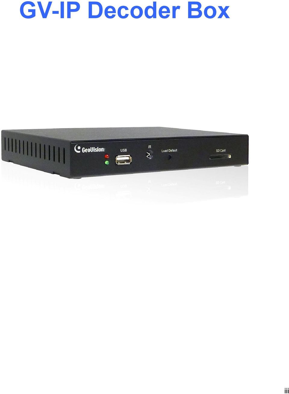
1 GV-IP Decoder Box and GV-Pad User s Manual V1.01 Before attempting to connect or operate this product, please read these instructions carefully and save this manual for future use. DBV101-A-EN

2 2012 GeoVision, Inc. All rights reserved. Under the copyright laws, this manual may not be copied, in whole or in part, without the written consent of GeoVision. Every effort has been made to ensure that the information in this manual is accurate. GeoVision, Inc. makes no expressed or implied warranty of any kind and assumes no responsibility for errors or omissions. No liability is assumed for incidental or consequential damages arising from the use of the information or products contained herein. Features and specifications are subject to change without notice. Note: no SD card slot or local storage function for Argentina. GeoVision, Inc. 9F, No. 246, Sec. 1, Neihu Rd., Neihu District, Taipei, Taiwan Tel: Fax: Trademarks used in this manual: GeoVision, the GeoVision logo and GV series products are trademarks of GeoVision, Inc. Windows and Windows XP are registered trademarks of Microsoft Corporation. January 2012

3 GV-IP Decoder Box Content Chapter 1 Introduction Features Compatible Devices Packing List Optional Accessories Overview Front View Rear View The IR Remote Control...7 Chapter 2 Getting Started Installing the GV-IP Decoder Box Connecting the GV-IP Decoder Box Configuring the IP Address, ID and Password Displaying Channels from GV IP Devices Displaying Channels Using GV IP Device Utility Displaying Channels from GV-System Taking a Snapshot Pausing the Looped View Controlling PTZ Cameras...30 Chapter 3 System Setup Searching IP Devices Setting the Network Configuring the Play Mode Adding a GV IP Device Configuring the Account, Storage and Output Type Upgrading the Firmware Updating Firmware through USB Drive or SD Card Updating Firmware through GV IP Device Utility...38 Specifications...40 Chapter 4 Introduction Features Compatible Devices Packing List Optional Accessories Overview...45 i

4 4.5.1 Right Panel View Left Panel View The IR Remote Control...47 Chapter 5 Getting Started Installing the GV-Pad Connecting the GV-Pad Configuring the Basics Managing the GV-Pad...51 Chapter 6 System Setup...52 Specifications...53 ii

5 GV-IP Decoder Box iii
6

7 Chapter 1 Introduction The GV-IP Decoder Box is designed to decode incoming IP streams from GeoVision and third-party IP devices, and displaying them on a digital or an analog monitor. To be used with only a monitor, the GV-IP Decoder Box provides a cost-effective solution for video surveillance as opposed to the traditional DVR and PC setup. The security administrator can monitor channels, take snapshots of critical moments, and pause at a channel when events occur, all through the supplied remote control. Connected GeoVision PTZ cameras such as GV-PTZ010D, GV-PT110D and GV-IP Speed Dome can also be controlled through GV-Joystick. GV-IP Decoder Box GV-Video Server or LAN GV-Compact DVR Computer installed with GV- System & GV-Mobile Server Analog camera GV-IP Camera GV-PT/PTZ GV-IP Speed Dome 3rd party IP cameras that support RTSP, ONVIF or PSIA GV-IP Device, analog camera and some 3 rd party IP Devices Figure 1-1 1

8 1.1 Features Decode video streams in H.264 codec at a maximum frame rate of the IP device Decode up to 5 megapixel IP cameras Decode up to 64 IP streams Support for 3 rd party IP cameras that adhere to RTSP, ONVIF or PSIA Support for 10/100 Ethernet over LAN Support for single and sequential display VGA and High Definition Video outputs Video output resolution up to 1080p Support for GV-Joystick control of GV PTZ cameras (GV-PTZ010D and GV-PT110D) and GV-IP Speed Dome Support for remote firmware upgrade, IP address configuration and addition of new channel Display of Matrix view through GV-Mobile Server IR remote control SD card and USB drive for snapshot storage and firmware upgrade 2
 and GV-IP Speed Dome Support for remote firmware upgrade, IP address configuration and addition")
9 1 Introduction 1.2 Compatible Devices The GV-IP Decoder Box is compatible with: 1. Most GeoVision IP devices (of the indicated firmware versions) using H.264 codec, and 2. Third-party IP devices that support H.264 and adhere to RTSP, ONVIF or PSIA. Supported GeoVision IP Devices Device Type Models Firmware Versions Box Camera Bullet Camera Cube Camera Fixed Dome Vandal Proof IP Dome Mini Fixed Dome PT Camera PTZ Camera GV-BX110D All models (except GV-BX110D) GV-BL110D All models (except GV-BL110D) All models GV-MFD110 All models (except GV-MFD110) GV-PT110D GV-PTZ010D V1.08 or later V1.06 or later V1.08 or later V1.06 or later V1.06 or later V1.08 or later V1.06 or later V1.08 or later Speed Dome All models V1.02 or later Video Server GV-VS04H GV-VS11 GV-VS12 V1.04 or later V1.0 or later V1.05 or later Compact DVR GV-Compact DVR V3 series only V1.0 or later IMPORTANT: The connected GeoVision and third-party channels must be set with H.264 codec to be compatible. To decode and display non-h.264 IP channels or analog channels, connect the devices to GV-System and access them through GV-Mobile Server. The supported devices are listed below. Supported Devices Connected to GV-System Analog cameras All models of GeoVision IP cameras, GV-Video Server, GV-Compact DVR, GV-IP Speed Dome, GV-Smart Box and GV-DSP LPR 11 brands of third-party IP cameras. For detail, see 3
 GV-BL110D All models (except GV-BL110D) All models GV-MFD110 All models (except GV-MFD110) GV-PT110D GV-PTZ010D V1.08 or later V1.06 or later V1.")
10 1.3 Packing List 1. GV-IP Decoder Box 1 2. IR remote control 1 3. AC/DC adapter 1 (12 V, 3 A, 36 W) 4. Power cord x 1 5. Software DVD x Optional Accessories 1. Wall mount kit: L-type brackets x 2 Small screws x 4 2. VESA monitor mount kit: VESA monitor mount bracket x 1 L-type brackets x 2 Large screws x 4 Small screws x 8 3. GV-Joystick GV-Joystick x 1 USB Type A to Type B Cable x 1 GV-Joystick User s Manual x 1 4

11 1 Introduction 1.5 Overview This section identifies the components of the GV-IP Decoder Box Front View Figure 1-2 No. Name 1 LED Indicators 2 USB 3 IR 4 Default 5 SD Card Slot Function The green LED indicates the system is ready for use. The red LED indicates the power is supplied. Connect to a GV-Joystick, or to a USB storage device for local storage of snapshot and firmware upgrade. Built-in IR receiver to receive the IR signals from the IR remote control. Reset the GV-IP Decoder Box to the default factory settings. Use a pin to press the default button until the green LED fades. This will take about 10 seconds. The system will then reset and reboot itself shortly. Connect to an SD card for local storage of snapshot and firmware upgrade. 5

12 1.5.2 Rear View Figure 1-3 No. Name Function 1 Network Connect to the network. 2 High Definition Connect to a High Definition supported display device. 3 VGA Connect to a VGA monitor. 4 Power OFF/ON Switch the power on or off. 5 DC 12V Connect to power by using the supplied power adapter. Note: The SPDIF and L/R ports are not functional. 6

13 1 Introduction 1.6 The IR Remote Control Figure 1-4 No. Name Function 1 Power Turn on or off the GV-IP Decoder Box. 2 Numeric / Alphabetical / Punctuation Marks keys Enter numbers, alphabets or punctuation marks. 3 Back Back to the previous page in the Setup Menu. Move up, down, right and left in the Setup Menu. 4 Arrow Right arrow key: select a channel on the Device List. 5 REC Capture a snapshot. Left arrow key: unselect a channel on the Device List. 7

14 No. Name Function Start or stop sequential display. 6 Loop Start / Stop Display and fix at a channel: press the Loop Start / Stop key, a numeric key and OK to display and fix at the selected channel. Press 0 and OK to return to the last displayed channel. 7 Menu Switch to the setup menu. 8 OK Save settings in the Setup Menu. Display selected channels. Switch among the 8 resolutions. When the key is pressed, the Green LED on the front panel flashes. Press No. 0 ~ 7 for the desired resolution within 30 seconds. 9 Shift Shift + 0 : VGA_640 x 480 Shift + 1 : VGA_1024 x 768 Shift + 2 : VGA_1280 x 768 Shift + 3 : VGA_1366 x 768 Shift + 4 : High Definition_480p Shift + 5 : High Definition_720p Shift + 6 : High Definition_1080i Shift + 7 : High Definition_1080p Note after the resolution is configured, the green LED will fade and GV-IP Decoder Box will reboot automatically. 10 INFO Shows the camera name and total number of cameras under display. 8

15 Chapter 2 Getting Started 2.1 Installing the GV-IP Decoder Box You can install the GV-IP Decoder Box on wall, behind a VESA monitor or simply use it as desk mount device. Wall Mount Installation For wall mount installation, you need to purchase the wall mount kit. 1. Unscrew the 4 screws on the back panel of the GV-IP Decoder Box. Figure Use the 4 small screws in the package to tighten the L-type brackets on the GV-IP Decoder Box. Figure 2-2 9

16 VESA Monitor Mount For VESA monitor mount, you need to purchase VESA Monitor mount kit. 1. Follow steps 1 and 2 in Wall Mount Installation to install the L-type brackets on the back panel of GV-IP Decoder Box. 2. Attach the VESA monitor mount bracket on the back of the computer monitor with 4 large screws. Figure Secure the GV-IP Decoder Box with the VESA monitor mount bracket together with 4 small screws. Figure

17 2 Getting Started 2.2 Connecting the GV-IP Decoder Box Follow the steps below to connect the GV-IP Decoder Box: Figure Connect a display device to VGA connector or High Definition connector for video output. 2. Connect to a standard network cable. 3. Connect to power using the supplied power adapter. 4. Turn the Power switch to ON. Note: 1. You can only connect the GV-IP Decoder Box to one display device through the High Definition or VGA connector. 2. The default video output is set to VGA with 1024 x 768 resolutions. If you use a High Definition monitor, be sure to change the output type. To change the default setting or configure the output type, see 3.5 Configuring the Account, Storage and Output Type. 11

18 2.3 Configuring the IP Address, ID and Password After you have installed and connected the necessary cables, you are ready to configure the IP address, ID and password. The GV-IP Decoder Box supports two types of network environments: fixed IP address and DHCP for dynamic IP address assignment. Depending on your network, set up a static IP address or choose DHCP for dynamic IP address assignment by the DHCP server. The GV-IP Decoder Box contains two sets of ID and password: one set is required when configuring GV-IP Decoder Box through GV-IP Device Utility; the other set is for direct connection between GV IP devices and GV-IP Decoder Box. Note: 1. By default, the GV-IP Decoder Box has the IP address of and the ID and password are admin. 2. Since all GV IP devices have the default IP address , it is advisable to configure the IP address of your GV-IP Decoder Box to avoid IP conflict. 3. When connecting to GV-IP Decoder Box (see 2.4 Displaying Channels from GV IP Devices), the GV IP devices need to have the same ID and password set on the GV-IP Decoder Box. 1. Power on your GV-IP Decoder Box. The main menu appears. Figure

19 2 Getting Started 2. To configure the IP address, follow the steps below. A. On the main menu, select the icon and press OK. This window appears. Figure 2-7 B. If you want to use the IP address assigned by the DHCP server under the LAN, select Yes for the DHCP option, and press OK to confirm. C. If you want to set up a static IP address, type the network information as required and press OK. D. The system will restart and the green LED will fade. Wait for the green LED to return. 3. To configure ID and password for GV-IP Decoder Box, follow the steps below. A. On the main menu, select the icon and press OK. This window appears. Figure


20 B. Type the ID and password and press OK to confirm. The maximum number of characters is To configure the ID and password for GV IP device connection, follow the steps below. A. On the main menu, select the icon and press OK. This window appears. Figure 2-9 B. Type the ID and password and press OK to confirm. The maximum number of characters is 15. Tip: You may also use GV IP Device Utility to modify the IP address by clicking the GV-IP Decoder Box and selecting Configure. 14

21 2 Getting Started 2.4 Displaying Channels from GV IP Devices Use the search feature on GV-IP Decoder Box to display channels from GV IP devices installed under the same LAN. Before you start: This method only applies to GeoVision IP devices under the same LAN with GV-IP Decoder Box. The NVR port (of GV-IP Decoder Box) and VSS port (of GV IP Devices) must be the same. The ID and password set on GV IP devices and GV-IP Decoder Box (step 4 in 2.3 Configuring the IP Address, ID and Password) must be the same. Note: 1. To add third-party IP channels, see 2.5 Displaying Channels Using GV IP Device Utility. 2. To add channels connected to GV-System, see 2.6 Displaying Channels from GV-System. 1. Select the icon and press OK. The GV IP devices under the same LAN with the GV-IP Decoder Box will appear on the Device List Figure
22 2. To select channels, press the up and down arrow keys (No.4, Figure 1-4) and press the right arrow key. The yellow shows the cursor position and the selected channels will be in red. Figure Press the OK key. The selected channels will be displayed. Note: 1. When the system idles over 30 seconds or resumes after power interruption, the GV-IP Decoder Box will automatically display channels based on the last successful settings. 2. Every time when the search function is performed, any channels selected previously on the Device List will be unselected. 16
 and third-party IP")
23 2 Getting Started 2.5 Displaying Channels Using GV IP Device Utility You may utilize the GV IP Device Utility to add and display channels from GV IP devices, GV-System (through GV-Mobile Server) and third-party IP devices that adhere to RTSP, ONVIF or PSIA. Note: 1. The GV-IP Decoder Box can decode a total of 64 channels from GeoVision and third-party IP devices. 2. GV IP Device Utility is available on Software DVD. ONVIF and PSIA support is only available on the GV IP Device Utility V8.53. Figure

24 1. Make sure your GV IP devices, GV-System or third-party IP devices are under same LAN with the GV-IP Decoder Box. 2. Make sure you have installed the GV IP Device Utility program. Double-click the GV IP Device Utility icon on the desktop. The GV IP Device Utility window appears. It will automatically search for all the GV IP devices under the same LAN. Figure Click on the IP address of your GV-IP Decoder Box and select Connect Setting. This dialog box appears. Figure
25 2 Getting Started 4. Type the ID and password of your GV-IP Decoder Box and click OK. For detail, see step 3 in 2.3 Configuring the IP Address, ID and Password. The Video Connection Setting window appears. The IP devices under the same LAN with the GV-IP Decoder Box will be listed in the Camera List column, and the connected channels will be listed in the Connection Information column. Figure To connect to a GV IP device or devices from GV-System, use the right and left buttons to add or remove the device. IMPORTANT: To select and connect to channels from GV-System, be sure you have run and configured GV-Mobile Server. For setup steps, see 2.6 Displaying Channels from GV-System. 6. Right-click the added channel, select Edit and type the username and password of the channel to log in. By default, the login ID and password for all GV IP devices are admin. 19

26 7. To add a third-party IP camera, follow the steps below. A. Click Tool on the Video Connection Setting window, and select Add Camera. This dialog box appears. Figure 2-16 B. Type the IP address, user name and password of the device. C. Select Protocol for Brand and one of the following protocol for Device Name. Type the RTSP command if required. Refer to your third-party IP camera s manual for this information. Figure 2-17 ONFIV: Select this protocol if your camera adheres to ONVIF. PSIA: Select this protocol if your camera adheres to PSIA. RTSP over HTTP: The RTSP protocol uses an HTTP port for data streaming from the IP camera. 20
27 2 Getting Started RTSP over TCP: The RTSP protocol uses a TCP port for data streaming from the IP camera. RTSP over UDP: The RTSP protocol uses a UDP port for data streaming from the IP camera. D. For ONVIF and PSIA, modify the Port to 80, else keep the port in default. E. Click OK. The camera will be added to the list. Figure Use the up and down buttons to move the added channels up and down the Connection Information list. The channels will be displayed according to this order. 9. Click Save. The cameras on the Connection Information column will be updated to the GV-IP Decoder Box and displayed on the monitor. Note: When the system idles over 30 seconds or resumes after power interruption, the GV-IP Decoder Box will automatically display channels based on the last successful settings. 21


28 2.6 Displaying Channels from GV-System You can access the analog and IP channels connected to GV-System through GV-Mobile Server. Through GV-Mobile Server, the GV-IP Decoder Box can decode and display: up to 32 H.264 and non-h.264 channels that are connected to GV-System. up to 4 channels of matrix view. GV-PT/PTZ GV-IP Speed Dome GV-IP Camera GV-Video Server LAN GV-IP Decoder Box Computer installed with GV-System & GV-Mobile Server GV-Compact DVR Some 3 rd party IP cameras Analog camera Figure 2-19 Note: 1. The GV-Mobile Server program can be found in the software DVD of GV-System. 2. For the compatible third-party IP devices with GV-System, visit 3. The GV-IP Decoder Box can decode a total of 64 channels from GeoVision and third-party IP devices. 22

29 2 Getting Started 1. Set up the desired IP channels on GV-System. For setup steps, see Chapter 2 Hybrid and NVR Solution in the Multicam Digital Surveillance System User s Manual in GV-System s accompanying software DVD. 2. Go to Windows Start, point to Programs, select GV-Mobile Server and run Mobile Server. The GV-Mobile Server window appears. Figure Click the GeoProtocol tab. This window appears. Figure

30 4. To connect directly with GV-IP Decoder Box, change the port to Note: If you are using GV-Mobile Server firmware before V1.2 and connect through GV IP Device Utility, modify the command port to Select Custom and type the ID and password of the GV-Mobile Server. To connect directly with GV-IP Decoder Box, the ID and password must match the CAM Login ID and password set on the GV-IP Decoder Box (Figure 2-9). 6. Configure each connected channel. A. Click a camera number on the device tree. This window appears. Figure 2-22 B. Type the frame rate in the FPS field and select a Quality and Resolution using the drop-down lists. The maximum resolution supported for streaming is 704 x 480. C. Select H.264 for Codec. Note: The GV-IP Decoder Box supports Stream 1 and H.264 codec only. D. Repeat steps A to C to configure another channel. 24

31 2 Getting Started 7. To establish matrix view, follow the steps below. A. On the GV-Mobile Server window, select a Matrix number from the device tree. This window appears. Figure 2-23 B. Type the frame rate in the FPS field and select a Quality and Resolution using the drop-down lists. The maximum resolution supported for streaming is 1.3 M. C. Select H.264 for Codec. Note: The GV-IP Decoder Box supports Stream 1 and H.264 codec only. 25
32 D. Click the Matrix Setting button. The window appears. Figure 2-24 E. Select a matrix pattern from the top. F. Click and drag channels from the device tree. G. Click OK. 8. Click Apply. 9. To preview, right click the channel in the left menu, and select one of the following: View Actual Stream: Watch the channel view received by the GV-Mobile Server. View Encode Stream 1: Watch the channel view set up in step 6 (for single channel) or step 7 (for matrix view). View Encode Stream 2: Stream 2 will not be received by the GV-IP Decoder Box. 26
33 2 Getting Started 10. To connect directly from GV-IP Decoder Box, follow the steps below. A. On the main menu of GV-IP Decoder Box, select and press OK to search. The channels of GV-Mobile Server will be listed. Figure 2-25 B. To select channels, press the up and down arrow keys (No.4, Figure 1-4) and press the right arrow key. The yellow shows the cursor position and the selected channels will be in red. C. Press the OK key. The selected channels will be displayed. 11. To connect using GV IP Device Utility, follow steps in 2.5 Displaying Channels Using GV IP Device Utility. 27
34 2.7 Taking a Snapshot The security administrators can capture images when events occur. Snapshot images are automatically saved to an inserted storage device such as a USB drive or SD card in JPEG format. Before you start, be sure: you have inserted a USB drive or SD card for storage. you have at least 30 MB of space on your storage device. the storage type is correctly configured. Otherwise, the error icon will appear when attempting to capture an image. 1. On the main menu, select and select the inserted storage device under Storage. 2. Press the key to capture the image. A camera icon appears at the top right corner of the monitor and 3 consecutive snapshots will be taken and saved to the inserted storage device. Figure
35 2 Getting Started 2.8 Pausing the Looped View You can pause the looped view and fix the display on a single channel. To pause the looped view, press the key. A loop sign with a cross will appear on the top-right corner of the display channel. To resume to the looped view, press the key again. Figure
36 2.9 Controlling PTZ Cameras The GV-Joystick can be connected to the GV-IP Decoder Box to control GV-PTZ010D, GV-PT110D and GV-IP Speed Dome. The supported functions include zoom in, zoom out, tilt (vertical movement), pan (horizontal movement), focus in, focus out and automatic focus. Note: 1. GV-Joystick cannot control channels accessed through GV-Mobile Server or RTSP. 2. The Previous and Next buttons of GV-Joystick are not supported on GV-IP Decoder Box. 3. The Focus In / Out buttons are not supported on GV-PT110D. 1. Connect a GV-Joystick to the USB port on the front panel. Once the GV-Joystick is connected, the PTZ icon will appear on the channels that support the device. Figure If you have more than one channel under display, press the key to lock the display channel at the PTZ camera. See 2.8 Pausing the Looped View. 3. You can now start to control the camera using the GV-Joystick. Tip: To automatically focus the channel view, press the Focus In and Focus Out buttons on the GV-Joystick at the same time. 30
37 Chapter 3 System Setup When the GV-IP Decoder Box is connected and powered on, the main menu appears on your display monitor: Figure 3-1 Icon Main Functions Search for GV IP devices and GV-Mobile Server under the same LAN with the GV-IP Decoder Box and generates a Device List. For detail, see 3.1 Searching IP Devices. Contains network settings of the GV-IP Decoder Box. For detail, see 3.2 Setting the Network. Contains the settings for IP devices to be displayed on GV-IP Decoder Box. For detail, see 3.3 Configuring the Play Mode. Adds a GV IP device to the GV-IP Decoder Box Device List and contains sorting options for the Device List. For detail, see 3.4 Adding a GV IP Device. Contains settings for account, storage, monitor type, resolution, and firmware upgrade. For detail, see 3.5 Configuring the Account, Storage and Output Type. 31
38 3.1 Searching IP Devices You can search the GV IP devices and Mobile Server under the same LAN with the GV-IP Decoder Box. 1. Use the arrow keys to select and press OK. The message Waiting to Scan appears. 2. Wait for a few seconds and the Device List appears. Figure Use the and the keys to view the list. 32
39 3 System Setup 3.2 Setting the Network To configure the network settings for the GV-IP Decoder Box, on the main menu, select and press OK. This window appears. Figure 3-3 DHCP: Select Yes to enable the DHCP function; No to disable the function. IP Address: Enter the IP address of the GV-IP Decoder Box. Mask: Enter the mask address of the GV-IP Decoder Box. DNS: Enter the DNS address of the GV-IP Decoder Box. Gateway: Enter the gateway address of the GV-IP Decoder Box. MAC: Shows the MAC address of the GV-IP Decoder Box. Connected IP: Shows the current IP address at use. 33
40 3.3 Configuring the Play Mode You can configure the play mode for the live view display. On the main menu, select press OK. This window appears. and Figure 3-4 CAM Loop Time Interval: Enter the time interval (in seconds) between each looped channel. The valid range is from 10 to 600. The default is 30 seconds. CAM Login ID: Enter the ID of the camera. The default is admin. The maximum number of characters is 15. CAM Login Password: Enter the password of the camera. The default is admin. The maximum number of characters is 15. NVR Port: Keep the NVR port in default (10000). Modify it only when necessary. Note: The channels added directly with GV-IP Decoder Box for display must also have the same ID and password established here. 34
41 3 System Setup 3.4 Adding a GV IP Device You can manually add a GV IP device, select the sorting method and configure the displayed information on the Device List. On the main menu, select appears. and press OK. This window Figure 3-5 Add IP Address: Type the IP address of the GV IP device. Note: This function is not applicable to adding third-party IP devices. To add third-party IP cameras, see 2.5 Displaying Channels Using GV IP Device Utility. Sort: Sort the Device List (Figure 3-2) according to IP address, MAC address, camera name or NONE. (When NONE is selected, the IP devices will be listed in the order of search). The default is By IP Address. Field Display: Select or unselect the device name and/or MAC address displayed on the Device List. The yellow block represents a selected option. Tip: Select the Name option only to display the device name and the channel number. 35
42 3.5 Configuring the Account, Storage and Output Type You can configure the account information, select storage and monitor connector, and look up firmware version. On the main menu, select This window appears. of the GV-IP Decoder Box and press OK. Figure 3-6 User Login ID: Type the login ID for the GV-IP Decoder Box. The default is admin. The maximum number of characters is 14. User Login Password: Type the password for the GV-IP Decoder Box. The default is admin. The maximum number of characters is 14. Device Name: Name your GV-IP Decoder Box. Storage: Select the inserted storage device (USB or SD). Output: Select the output format between VGA and High Definition. The available options for resolution will be automatically brought up. Resolution: Select a resolution. The system will reboot when the resolution is modified. Firmware Update: Select the device that stores the firmware files. For upgrading steps. See 3.6 Upgrading the Firmware. Firmware Version: Displays the firmware version of the device. 36
43 3 System Setup 3.6 Upgrading the Firmware We will periodically release the updated firmware on the website. You may choose to update firmware locally using a USB drive or SD card, or remotely through the GV IP Device Utility program. Before you start: Be sure you have inserted a storage device (USB drive or SD card) and it contains one firmware file only. The USB drive or SD card must have at least 100 MB of free space Updating Firmware through USB Drive or SD Card 1. Copy the firmware file to the root folder of a USB storage device or a SD card. 2. Connect the USB drive or SD card to the GV-IP Decoder Box. 3. On the setup menu, select and press OK. This window appears. Figure In the Firmware Update field, select USB or SD storage that stores the firmware file. 5. Press OK. The firmware upgrade runs automatically, and the GV-IP Decoder Box will restart after the firmware upgrade is completed. 37


44 3.6.2 Updating Firmware through GV IP Device Utility 1. On the main menu of GV-IP Decoder Box, select and select the inserted storage device under Storage. Figure Make sure you have installed the GV IP Device Utility program. Double-click the GV IP Device Utility icon on the desktop. This window appears. Figure Click on the IP address of your GV-IP Decoder Box and select Configure. This window appears. 38
45 3 System Setup Figure Select the Firmware Upgrade tab, type the User Name and Password, and click the Browse button to locate the firmware file saved at your local computer. Figure Type the password and click Upgrade to start upgrading. The system will reboot itself when the upgrade is completed. 39
46 Specifications Video Video Codec H.264 High Definition VGA 480p 640 x 480 Video Output at 60 Hz 720p 1024 x i 1280 x p 1366 x 768 Network Interface Protocol 10/100 Ethernet TCP, RTSP, ONVIF, PSIA Mechanical IR Remote Control Power Ethernet Connectors Monitor Output Local Storage & Firmware Upgrade Yes 12V DC Jack RJ-45 High Definition, VGA USB slot (2.0 backward compatible, FAT32 format) SD card slot (for Class 6 card or above, FAT32 format) General Operating Temperature 0 C ~ 40 C / 32 F ~ 104 F Operating Humidity 20 % ~ 80 % (with no condensation) Dimensions (W x H x D) mm / in Net Weight 615 g / 1.36 lb Power DC 12 V Power Consumption 36 W (max. 3 A at 12V DC) Regulatory CE, FCC compliant All specifications are subject to change without notice. 40
47 4 Introduction GV-Pad 41

48 Chapter 4 Introduction The GV-Pad is a pad that decodes and displays incoming IP streams from GeoVision and third-party IP devices. It is light-weighted and requires only minimal amount of installation. As a standalone device, the GV-Pad does not require an extra monitor and yet it supports almost all the features of a GV-IP Decoder Box. Through the network, a GV-Pad can receive and manage up to 64 IP streams simultaneously. The administrators can monitor channels, take snapshots, pause at a specific channel and control GeoVision PTZ cameras such as GV-PTZ010D, GV-PT110D and GV-IP Speed Dome through a connected GV-Joystick. GV-Pad GV-Video Server or LAN GV-Compact DVR Computer installed with GV- System & GV-Mobile Server Analog camera GV-IP Camera GV-PT/PTZ GV-IP Speed Dome 3rd party IP cameras that support RTSP, ONVIF or PSIA GV-IP Device, analog camera and some 3 rd party IP Devices Figure
49 4 Introduction 4.1 Features Decode video streams in H.264 codec at a maximum frame rate of the IP device Decode up to 5 megapixel IP cameras Decode up to 64 IP streams Support for 3 rd party IP cameras that adhere to RTSP, ONVIF or PSIA Support for 10/100 Ethernet over LAN Support for single and sequential display Support for GV-Joystick control of GV PTZ cameras (GV-PTZ010D and GV-PT110D) and GV-IP Speed Dome Support for remote firmware upgrade, IP address configuration and addition of new channel IR remote control SD card and USB drive for snapshot storage and firmware upgrade 4.2 Compatible Devices The GV-Pad compatible devices are the same with those for GV-IP Decoder Box. For detail, see 1.2 Compatible Devices. 4.3 Packing List 1. GV-Pad 1 2. IR remote control 1 3. Magnetic hinge x 1 4. Screw x 4 5. AC/DC adapter 1 (12 V, 3 A, 36 W) 6. Power cord x 1 7. Software DVD x 1 43
50 4.4 Optional Accessories GV-Joystick GV-Joystick x 1 USB Type A to Type B Cable x 1 GV-Joystick User s Manual x 1 44
51 4 Introduction 4.5 Overview This section identifies the components of the GV-Pad Right Panel View Figure 4-2 No. Name 1 SD Card Slot 2 USB 3 LED Indicators 4 IR Function Connect to an SD card for local storage of snapshot and firmware upgrade. Connect to a GV-Joystick, or to a USB storage device for local storage of snapshot and firmware upgrade. The green LED indicates the system is ready for use. The red LED indicates the power is supplied. Built-in IR receiver to receive the IR signals from the IR remote control. 5 Network Connect to the network. 45
52 4.5.2 Left Panel View Figure 4-2 No. Name Function Switch to the setup menu. 1. MENU 2 ENTER Load default: Press for 10 seconds to load default settings. Save settings in the Setup Menu. Display selected channels. 3 UP Move the cursor up. 4 DOWN Move the cursor down. 5 LEFT Move the cursor left. Unselect a channel on the Device List. 46
53 4 Introduction No. Name 6 RIGHT 7 STAND BY Function Move the cursor right. Select a channel on the Device List. Press to enter the Standby mode. In the standby mode, the screen turns off to minimize power consumption. Press the key again to enter the ON mode. 8 Power OFF/ON Switch the power on or off. 9 DC 12V Connect to power using the supplied power adapter. 4.6 The IR Remote Control The supplied IR remote control for GV-Pad is the same with GV-IP Decoder Box. For the functions of each key, see 1.6 The IR Remote Control. Note: The Menu, OK, Arrow, and Power keys on the IR remote control are also available on the left panel of the GV-Pad. For detail, see Left Panel View. 47
54 Chapter 5 Getting Started 5.1 Installing the GV-Pad The GV-Pad can be used as a desktop device, installed on the wall or adhere to a magnetic surface. Note: To mount your GV-Pad on the wall, be sure to prepare 4 screws to secure the device to the wall. 1. Secure the magnetic hinge to the back of the GV-Pad with 4 screws. 2. Adjust the angle of the magnetic hinge according to your needs. 3. To install the GV-Pad on a wall, secure the magnetic hinge with self-prepared screws. 4. Connect the necessary wires and cables. See 5.2 Connecting the GV-Pad. 48
55 5 Getting Started 5.2 Connecting the GV-Pad Follow the steps below to connect the GV-Pad: Figure Connect to power using the supplied power adapter. 2. Connect to a standard network cable. 3. Turn the Power switch to ON. 49
56 5.3 Configuring the Basics After you have installed and connected the necessary wire and cable to your GV-Pad, you are ready to configure the GV-Pad. 1. Configure the IP address, ID and password. See 2.3 Configuring the IP Address, ID and Password. Note: 1. Since all the GV IP devices have the default IP address Therefore, it is strongly advisable to modify the IP address to avoid IP conflict. 2. The default ID and password are admin. 3. The IP devices to be connected need to have the same ID and password set on the GV-Pad. 2. Display channels. The GV-Pad can display up to 64 IP channels from GeoVision and/or third-party devices. Refer to the sections indicated below to set up the channels. Functions To display channels from GV IP devices To display channels form third-party IP devices To display channels connected to GV-System Reference See 2.4 Displaying Channels from GV IP Devices See 2.5 Displaying Channels Using GV IP Device Utility See 2.6 Displaying Channels from GV-System 50
57 5 Getting Started 5.4 Managing the GV-Pad The administrator can take snapshots, pause at a single channel and control PTZ cameras. Functions Taking a snapshot Pausing at a channel Controlling PTZ cameras Reference See 2.7 Taking a Snapshot See 2.8 Pausing the Lopped View See 2.9 Controlling PTZ Cameras 51


58 Chapter 6 System Setup When the GV-Pad is connected and powered on, the main menu appears: Figure 6-1 Icon Main Functions Search for GV IP devices and GV-Mobile Server under the same LAN with the GV-Pad and generates a Device List. For detail, see 3.1 Searching IP Devices. Contains network settings of the GV-Pad. For detail, see 3.2 Setting the Network. Contains the settings for IP devices to be displayed on GV-Pad. For detail, see 3.3 Configuring the Play Mode. Adds a GV IP device to the Device List and contains sorting options for the Device List. For detail, see 3.4 Adding a GV IP Device. Contains settings for account, storage, monitor type, resolution, and firmware upgrade. For detail, see 3.5 Configuring the Account, Storage and Output Type. 52
59 Specifications Specifications Video Video Codec H.264 Resolution 1280 x 800 Network Interface Protocol 10/100 Ethernet TCP, RTSP, ONVIF, PSIA Mechanical IR Remote Control Power Ethernet Connectors Local Storage & Firmware Upgrade Yes 12V DC Jack RJ-45 USB slot (2.0 backward compatible, FAT32 format) SD card slot (for Class 6 card or above, FAT32 format) General Operating Temperature 0 C ~ 40 C / 32 F ~ 104 F Operating Humidity 20 % ~ 80 % (with no condensation) Dimensions (W x H x D) mm / 13.5 x 8.7 x 1.5 in Net Weight 1160 g / 2.6 lb Power DC 12 V Power Consumption 36 W (max. 3 A at 12V DC) Regulatory CE, FCC compliant All specifications are subject to change without notice. 53
GV-Eye Mobile App. Contents
 GV-Eye Mobile App. Contents GV-Eye... 2 1.1 Specifications... 2 1.2 Supported GV-IP Devices and Software... 3 1.2.1 Supported Products... 3 1.2.2 Supported Products for Monitoring Activation... 4 1.2.3
GV-Data Capture V3 Series User's Manual
 GV-Data Capture V3 Series User's Manual Before attempting to connect or operate this product, please read these instructions carefully and save this manual for future use. 2006 GeoVision, Inc. All rights
GV-Keyboard. User's Manual V2.0
 GV-Keyboard User's Manual V2.0 Before attempting to connect or operate this product, please read these instructions carefully and save this manual for future use. 2007 GeoVision, Inc. All rights reserved.
Quick Start Guide. 1 Introduction. GV-Mobile Server V1.4. Packing List
 1 Introduction Welcome to the GV-Mobile Server Quick Start Guide. You will be guided through the basic installation and configuration of GV-Mobile Server. For the detailed user s manual, see GV-Mobile
GV-Mobile Server User's Manual V1.3
 GV-Mobile Server User's Manual V1.3 MBSV13-A 2012 GeoVision, Inc. All rights reserved. Under the copyright laws, this manual may not be copied, in whole or in part, without the written consent of GeoVision.
Quick Start Guide. GV-Control Center V3.1.0.0
 Quick Start Guide GV-Control Center V3.1.0.0 Thank you for purchasing GV-Control Center. This guide is designed to assist the new user in getting immediate results from the GV-Control Center. For advanced
Quick Start Guide. GV-Redundant Server GV-Failover Server. 1 Introduction. Packing List
 1 Introduction Quick Start Guide GV-Redundant Server GV-Failover Server Welcome to the GV-Redundant Server / Failover Server Quick Start Guide. In the following sections, you will be guided through the
AXIS Camera Station Quick Installation Guide
 AXIS Camera Station Quick Installation Guide Copyright Axis Communications AB April 2005 Rev. 3.5 Part Number 23997 1 Table of Contents Regulatory Information.................................. 3 AXIS Camera
How To Set Up A Network Camera On A Network Cable Extender (Rj45) With A Network Cam (Cms) On A Pc Or Mac) With An Ipad Or Ipad (For Awn) With The Power Cable (
 With A Network Cam (Cms) On A Pc Or Mac) With An Ipad Or Ipad (For Awn) With The Power Cable (") OUTDOOR IR NETWORK CAMERA SERIES Installation Guide Please read instructions thoroughly before operation and retain it for future reference. TABLE OF CONTENTS 1. OVERVIEW... 1 1.1 Package Content... 1
OUTDOOR IR NETWORK CAMERA SERIES Installation Guide Please read instructions thoroughly before operation and retain it for future reference. TABLE OF CONTENTS 1. OVERVIEW... 1 1.1 Package Content... 1
Table of Contents. Chapter1. Introduction...1. 1.1 Before Installation... 1 1.2 System Requirements... 1
 Table of Contents Chapter1. Introduction...1 1.1 Before Installation... 1 1.2 System Requirements... 1 Chapter2. IVS-110 1-Channel Internet Video Server...2 2.1 Package Content... 2 2.2 Physical Installation...
The GV-I/O Box 8 Ports provides 8 inputs and 8 relay outputs, and supports both DC and AC output voltages.
 GV-I/O Box 8 Ports The GV-I/O Box 8 Ports provides 8 inputs and 8 relay outputs, and supports both DC and AC output voltages. Key Features 8 inputs and 8 outputs are provided. Up to 9 pieces of GV-I/O
CX Series. Video Recording Server. Quick Start Guide CX784 / CX788 / CX7816. Version 1.05.00
 CX Series Video Recording Server CX784 / CX788 / CX7816 Quick Start Guide Version 1.05.00 Contents 1.Introduction...1 1.1.Packages Contents...1 1.2.Hardware Features...2 1.3.Functional Features...4 1.4.Hard
Additional Requirements for ARES-G2 / RSA-G2. One Ethernet 10 Base T/100 Base TX network card required for communication with the instrument.
 TA Instruments TRIOS Software Installation Instructions Installation Requirements Your TRIOS Instrument Control software includes all the components necessary to install or update the TRIOS software, as
PowerVideo Plus. EverFocus Central Management Software. for Networked Video Devices Management. User s Manual
 EverFocus Central Management Software for Networked Video Devices Management User s Manual Copyright EverFocus Electronics Corp. Release Date: January, 2013 Copyright 2012 EverFocus Electronics Corp. All
The GV-I/O Box 16 Ports provides 16 inputs and 16 relay outputs, and supports both DC and AC output voltages.
 GV-I/O Box 16 Ports The GV-I/O Box 16 Ports provides 16 inputs and 16 relay outputs, and supports both DC and AC output voltages. Key Features 16 inputs and 16 outputs are provided. Up to 9 pieces of GV-I/O
ENR-2000 Series. User s Manual. For V4.00.02 Firmware 2014/01/29
 ENR-2000 Series User s Manual For V4.00.02 Firmware 2014/01/29 Legal Notice Disclaimer The information contained in this document is intended for general information purposes. ACTi Corporation shall not
4-CH Hybrid Digital Video Recorder
 4-CH Hybrid Digital Video Recorder Key Features Hardware Embedded, highly-reliable standalone HDVR Supports 4-ch BNC connectors Supports dual local display (VGA and HDMI) Supports 3.5" SATA x 1 HDD Supports
Quick Start Guide NVR DS-7104NI-SL/W NVR. www.hikvision.com. First Choice For Security Professionals
 Quick Start Guide NVR DS-7104NI-SL/W NVR NOTE: For more detailed information, refer to the User s Manual on the CD-ROM. You must use your PC or MAC to access the files. www.hikvision.com Quick Start 1.
Central Management System (CMS) USER MANUAL
 USER MANUAL") Central Management System (CMS) USER MANUAL LEGAL INFORMATION Reproduction, transfer, distribution or storage of part or all of the contents in this document in any form without the prior written permission
Central Management System (CMS) USER MANUAL LEGAL INFORMATION Reproduction, transfer, distribution or storage of part or all of the contents in this document in any form without the prior written permission
7. Mobile Phone Support
 7. Mobile Phone Support A state-of-the-art feature of this DVR device is transmitting live feed from the CCTV cameras to your mobile phone, so that you can have on the go access to your surveillance system
How To Set Up Flir Cloud Client For Pc Or Mac Or Mac (For Pc Or Ipad) On A Pc Or Pc Or Mouse (For Mac) On An Iphone Or Ipa) On Pc Or Tv (For Ipa
 On A Pc Or Pc Or Mouse (For Mac) On An Iphone Or Ipa) On Pc Or Tv (For Ipa") Instruction Manual FLIR Cloud Services Client Instruction Manual FLIR Cloud Services Client #LX400018; r. 2.0/14567/14568; en-us iii Table of contents 1 Setting up FLIR Cloud Client for PC or Mac...1
Instruction Manual FLIR Cloud Services Client Instruction Manual FLIR Cloud Services Client #LX400018; r. 2.0/14567/14568; en-us iii Table of contents 1 Setting up FLIR Cloud Client for PC or Mac...1
Quick Start Guide. Plug n Play NVR DS-7604NI-E1/4P DS-7608NI-E2/8P. www.hikvision.com/en/us
 Quick Start Guide Plug n Play NVR DS-7604NI-E1/4P DS-7608NI-E2/8P Note: For more information refer to the complete User Manual located on the CD-ROM OVERVIEW 1. Overview 2. Main Menu Layout 3. Formatting
User s Manual of DVR DVS Remote Client Software V 4.0.1
 User s Manual of DVR DVS Remote Client Software V 4.0.1 Index Version description...4 1 Introduction...8 2 Software Install, Uninstall and use...9 2.1 Install remote client software ver4.0.1...9 2.2 Uninstall
3.5 EXTERNAL NETWORK HDD. User s Manual
 3.5 EXTERNAL NETWORK HDD User s Manual Table of Content Before You Use Key Features H/W Installation Illustration of Product LED Definition NETWORK HDD Assembly Setup the Network HDD Home Disk Utility
Network Video Recorder. Operation Manual
 Network Video Recorder Operation Manual Content 1 Product Description... 1 1.1 Product Overview... 1 1.2 Specification... 1 2 Product Structure Introduction... 2 2.1 Back Interface... 2 2.2 Front Panel...
Wifi Pan/Tilt IP Camera User Manual
 Wifi Pan/Tilt IP Camera User Manual Rev. 3.0 Software Version 3.00 May. 25 th.2009 Table of Contents 1. PRODUCT VIEWS...3 1.1. PRONT PANEL...3 1.2. BACK PANEL...3 1.3. ACCESSORIES...4 2. SETUP AND STARTUP...5
User Manual V1.0. Remote Software
 User Manual V1.0 Notice: The information in this manual was current when published. The manufacturer reserves the right to revise and improve its products. All specifications are therefore subject to change
Quick Start Guide. Hybrid DVR DS-90xxHFI-ST, DS-90xxHWI-ST Series. NVR DS-96xxNI-ST/RT Series. Plug n Play NVR DS-77xxNI-SP Series
 Quick Start Guide Hybrid DVR DS-90xxHFI-ST, DS-90xxHWI-ST Series NVR DS-96xxNI-ST/RT Series Plug n Play NVR DS-77xxNI-SP Series Note: For more information refer to the complete User Manual located on the
TENVIS Technology Co., Ltd. User Manual. For H.264 Cameras. Version 2.0.0
 TENVIS Technology Co., Ltd User Manual For H.264 Cameras Version 2.0.0 Catalogue Basic Operation... 3 Hardware Installation... 3 Search Camera... 3 Get live video... 5 Camera Settings... 8 System... 8
AXIS 262+ Network Video Recorder
 31433/EN/R4/0803 Complete Network Video Recording Solution Complete Network Video Recording Solution Picture this: A simple and reliable, plug-and-play video surveillance system for hotels, shops, banks,
Chapter 4 Control Center
 Chapter 4 Control Center Control Center is a central monitoring station solution (CMS) that provides the CMS operator with these major features: Access to client DVRs (See Remote DVR) Access to remote
KViewCenter Software User Manual 2012 / 04 / 20 Version 2.2.1.0
 KViewCenter Software User Manual 2012 / 04 / 20 Version 2.2.1.0 Table of Contents Chapter 1. KViewCenter Interface... 5 1.1. Log in.... 5 1.2. Log out... 5 1.3. Control Panel... 6 1.4. Control Panel (Preview
NVMS-1200. User Manual
 NVMS-1200 User Manual Contents 1 Software Introduction... 1 1.1 Summary... 1 1.2 Install and Uninstall... 1 1.2.1 Install the Software... 1 2 Login Software... 3 2.1 Login... 3 2.2 Control Panel Instruction...
Amcrest 960H DVR Quick Start Guide
 Amcrest 960H DVR Quick Start Guide Welcome Thank you for purchasing our Amcrest 960H DVR! This quick start guide will help you become familiar with our DVR in a very short time. Before installation and
Installation Steps Follow these steps to install the network camera on your local network (LAN):
:") 1. Description The Network Camera supports the network service for a sensor image with progressive scan, which can be monitored on a real-time screen regardless of distances and locations. By using its
1. Description The Network Camera supports the network service for a sensor image with progressive scan, which can be monitored on a real-time screen regardless of distances and locations. By using its
IDDERO TOUCH PANELS. Video door phone configuration. www.iddero.com 120130-02
 IDDERO TOUCH PANELS Video door phone configuration www.iddero.com 120130-02 TABLE OF CONTENTS 1 INTRODUCTION... 3 2 INSTALLATION... 3 3 INITIAL CONFIGURATION... 4 4 2N HELIOS IP VIDEO DOOR PHONES... 5
Network Video Recorder. User s Manual v1.0.0. Model: SVR-504/508/516/516+
 User s Manual v1.0.0 Model: SVR-504/508/516/516+ Table of Contents Product Description 6 Install Hard Disk 7 Hardware Illustration 10 I/O Ports and RS-485 12 LEDs Definition 13 Connect to the NVR 15 2
DVR-4TL/8TL/16TL Setup Guide
 Package Content DVR-4TL/8TL/16TL Setup Guide Inspect the DVR s packaging. Make sure that the DVR-4TL/8TL/16TL is packed properly. Remove all items from the box and make sure it contains the following items.
aseries DVR04/DVR08 DIGITAL VIDEO RECORDER Quick Operations Guide
 aseries DVR04/DVR08 DIGITAL VIDEO RECORDER Quick Operations Guide UD.7L0202B1365B01 Thank you for purchasing our product. If there is any question or request, please do not hesitate to contact dealer.
Welcome. Unleash Your Phone
 User Manual Welcome Unleash Your Phone For assistance with installation or troubleshooting common problems, please refer to this User Manual or Quick Installation Guide. Please visit www.vonage.com/vta
BlackHawk for MAC Software User Guide
 BlackHawk for MAC Software User Guide Products: BLK-DH2 Series and BLK-HD Series DVRs Please read this manual before using your software, and always follow the instructions for safety and proper use. Save
Access the GV-IP Camera through a broadband modem
 Access the GV-IP Camera through a broadband modem Applied to All GV-IP Cameras Article ID: GV15-12-03-26 Release Date: 03/26/2012 Introduction The document introduces how to connect your GV-IP Camera to
OPERATION MANUAL. MV-410RGB Layout Editor. Version 2.1- higher
 OPERATION MANUAL MV-410RGB Layout Editor Version 2.1- higher Table of Contents 1. Setup... 1 1-1. Overview... 1 1-2. System Requirements... 1 1-3. Operation Flow... 1 1-4. Installing MV-410RGB Layout
GV-iView HD V1 for ipad
 GV-iView HD V1 for ipad Article ID: GV10-11-03-07 Release Date: 03/07/2011 GV-iView HD V1 function is introduced to support ipad for the mobile surveillance application. System Requirements Handheld Device
IDDERO TOUCH PANELS. Video door phone configuration. www.iddero.com 120719-02
 IDDERO TOUCH PANELS Video door phone configuration www.iddero.com 120719-02 TABLE OF CONTENTS 1 INTRODUCTION... 3 2 INSTALLATION... 3 3 INITIAL CONFIGURATION... 4 4 2N HELIOS IP VIDEO DOOR PHONES... 5
CMS-DH CENTRAL MANAGEMENT SOFTWARE
 CMS-DH CENTRAL MANAGEMENT SOFTWARE CMS-DH is a central management software that allows you to view and manage up to 300 DH200 series DVRs. System Requirements Your system must meet the system requirements
USER S MANUAL. AXIS Mobile Monitor
 USER S MANUAL AXIS Mobile Monitor AXIS Mobile Monitor Overview Main window Main menu Find Devices Find Devices menu Monitor window Monitor menu Sequence window Sequence menu How to Use AXIS Mobile Monitor
TDP43ME NetPS. Network Printer Server. Control Center. for Ethernet Module
 Panduit Corp. 2010 TDP43ME NetPS PA26306A01 Rev. 01 11-2010 Network Printer Server Control Center for Ethernet Module NOTE: In the interest of higher quality and value, Panduit products are continually
Quick Installation Guide
 V48.01 Model: FI8919W Quick Installation Guide Outdoor Pan/Tilt Wireless IP Camera For Windows OS ------- Page 1 For MAC OS ------- Page 15 ShenZhen Foscam Intelligent Technology Co., Ltd Quick Installation
Megapixel PoE Day / Night Internet Camera TV-IP572PI (v1.0r)
") (v1.0r) PRODUCT OVERVIEW The Megapixel PoE Day / Night Internet Camera, model TV- IP572PI, transmits real-time Megapixel video over the Internet. Record crisp video in complete darkness for distances of
(v1.0r) PRODUCT OVERVIEW The Megapixel PoE Day / Night Internet Camera, model TV- IP572PI, transmits real-time Megapixel video over the Internet. Record crisp video in complete darkness for distances of
Wireless Day / Night Cloud Camera TV-IP751WIC (v1.0r)
") (v1.0r) TRENDnet s Wireless Day / Night Cloud Camera, model, takes the work out of viewing video over the internet. Previously to view video remotely, users needed to perform many complicated and time
(v1.0r) TRENDnet s Wireless Day / Night Cloud Camera, model, takes the work out of viewing video over the internet. Previously to view video remotely, users needed to perform many complicated and time
Coolmax CN-590 Network Storage Solution
 Coolmax CN-590 Network Storage Solution Model Name Controller hip CPU OS Memory Interface CN-590 S2892 150MHz RTOS 8MB SDRAM / 1MB NOR Flash LAN Standard 10/100Base-TX Auto MDI/MDI-X Connector Type RJ-45
ShareLink 200 Setup Guide
 ShareLink 00 Setup Guide This guide provides instructions for installing and connecting the Extron ShareLink 00. The ShareLink USB 00 Wireless Collaboration Gateway allows anyone to present content from
V.I.P. Kit. Video Insight Pilot Kit. (Video Insight Pilot Kit).
.") V.I.P. Kit (Video Insight Pilot Kit). Video Insight Pilot Kit Please follow these instructions and everything should go very smoothly. Before you begin, you will need to establish (or obtain from your
V.I.P. Kit (Video Insight Pilot Kit). Video Insight Pilot Kit Please follow these instructions and everything should go very smoothly. Before you begin, you will need to establish (or obtain from your
User s Manual. Copyright 2010 Vantec Thermal Technologies. All Rights Reserved.
 Copyright 2010 Vantec Thermal Technologies. All Rights Reserved. User s Manual Package Contents: 1 NextStar FX Gigabit NAS Adapter x1 2 AC Adapter x1 3 Installation Guide x1 4 Rubber Feet x4 5 User s CD
Configuring NXT Hardware with Mercury Inside into Doors.NET TM Application Note
 1.0 Installing the Mercury SCP Gateway The MSC/SCP gateway must be installed to interface with Mercury hardware. This gateway must be chosen during the installation of the software, or it can be added
Linksys WAP300N. User Guide
 User Guide Contents Contents Overview Package contents 1 Back view 1 Bottom view 2 How to expand your home network 3 What is a network? 3 How to expand your home network 3 Where to find more help 3 Operating
4. Rear View. Function Switches 1. Fixed IP 2. DHCP Floating IP 3. Auto IRIS (DC Driver LENS) 4. Fixed LENS (AES)
 4. Fixed LENS (AES)") 4. Rear View 5 1.STATIC IP 2.DHCP 3.DC IRIS Mini USB 1 2 3 4 5 6 1. ALM-RST 2. ALM-IN 3. ALM-OUT 4. GND 5. RS485-6. RS485 + 1 2 3 4 5 6 7 DC Power Input: DC Jackψ2.1, DC12V---0.5A or higher. LAN/WAN Network
4. Rear View 5 1.STATIC IP 2.DHCP 3.DC IRIS Mini USB 1 2 3 4 5 6 1. ALM-RST 2. ALM-IN 3. ALM-OUT 4. GND 5. RS485-6. RS485 + 1 2 3 4 5 6 7 DC Power Input: DC Jackψ2.1, DC12V---0.5A or higher. LAN/WAN Network
VFS24/32HDIP. Public Display IP Monitor User Manual
 VFS24/32HDIP Public Display IP Monitor User Manual 2 Contents Before You Begin...4 Side Panel Control buttons...6 Connections...7 OSD Function...7 LCD monitor Mounting Guide...9 Getting started... 10 Power
DS-7200HWI-SH/A Series DVR. Technical Specification
 DS-7200HWI-SH/A Series DVR Technical Specification Notices The information in this documentation is subject to change without notice and does not represent any commitment on behalf of HIKVISION. HIKVISION
PC-ZViewer User Manual
 PC-ZViewer User Manual For further help, please visit www.zmodo.com Contents Preface... 3 Statement... 3 Intended Reader... 3 Terms in this Manual... 3 Software Introduction... 3 Operating Environment...
Stand Alone Type. Digital Video Recorder USER S MANUAL. (Real time recording 8 & 16 CH DVR) Revision Date : 2010. 6. 30.
 Revision Date : 2010. 6. 30.") Stand Alone Type Digital Video Recorder USER S MANUAL (Real time recording 8 & 16 CH DVR) Revision Date : 2010. 6. 30. INDEX 1. Front Panel - - - - - - - - - - - - - - - - - - - - - - - - - - - - - - -
Stand Alone Type Digital Video Recorder USER S MANUAL (Real time recording 8 & 16 CH DVR) Revision Date : 2010. 6. 30. INDEX 1. Front Panel - - - - - - - - - - - - - - - - - - - - - - - - - - - - - - -
GV-Video Server. User's Manual
 GV-Video Server User's Manual Before attempting to connect or operate this product, please read these instructions carefully and save this manual for future use. VS04H.VS12V106.VS11V102.VS14V10-A 2012
INSTALLATION GUIDE. Assign an IP Address and Access the Video Stream
 INSTALLATION GUIDE Assign an IP Address and Access the Video Stream Liability Every care has been taken in the preparation of this document. Please inform your local Axis office of any inaccuracies or
H.264 Internet Video Server
 Key Features Video / Audio H.264 / MPEG-4 and M-JPEG video compression simultaneously Simultaneous multi-stream support Up to 30/25 (NTSC/PAL) fps for all profiles 3DNR (3D Noise Reduction) to improve
EV-1000 Series DVR. Quick Operation Guide. Version 1.0.0
 EV-1000 Series DVR Quick Operation Guide Version 1.0.0 Thank you for purchasing our product. If there is any question or request, please do not hesitate to contact dealer. This manual is applicable to
Network Projector Operation Guide
 Network Projector Operation Guide Table of contents Preparation...3 Connecting the projector with your computer...3 Wired connection... 3 Wireless connection (for selective models)... 4 QPresenter...7
Single-bay NAS Server
 Single-bay NAS Server NAS-1100 User s Manual Copyright (C) 2004 PLANET Technology Corp. All rights reserved. The products and programs described in this User s Manual are licensed products of PLANET Technology,
How to Remotely View Security Cameras Using the Internet
 How to Remotely View Security Cameras Using the Internet Introduction: The ability to remotely view security cameras is one of the most useful features of your EZWatch Pro system. It provides the ability
Wireless PTZ Cloud Camera TV-IP851WC (v1.0r)
") (v1.0r) TRENDnet s Wireless PTZ Cloud Camera, model, takes the work out of viewing video over the internet. Previously to view video remotely, users needed to perform many complicated and time consuming
(v1.0r) TRENDnet s Wireless PTZ Cloud Camera, model, takes the work out of viewing video over the internet. Previously to view video remotely, users needed to perform many complicated and time consuming
GV-AView for Android Smartphones & Tablets
 GV-AView for Android Smartphones & Tablets You can now access GV-System using Android version 2.2 to 4.1.2 to watch live view or play back recorded videos. Download GV-AView from Android Market, and after
1.3 CW-720. 1280x720 Pixels. 640x480 Pixels. 720P Wireless 150Mbps IPCAM. High Quality 720P MegaPixel Image
 CW-720 720P Wireless 150Mbps IPCAM 30FPS at 1.3 Mega Mode 30FPS at 720P Mode 150Mbps Wireless-B/G/N Use 10X Times Less Storage with H.264 Video Compression Micro SD Card Slot for Local Storage ios and
GV- RK1352 Card Reader
 GV- RK1352 Card Reader The GV-RK1352 is a card reader with keypad, designed to recognize PIN codes, identification cards or both. Featured with the Wiegand and RS-485 outputs, the unit can be connected
SEC-PCC10 SEC-PCC20 SEC-PCC30 PCI SECURITY CARD
 SEC-PCC10 SEC-PCC20 SEC-PCC30 PCI SECURITY CARD ADVANCED ENGLISH MANUAL 0 Installation 1. Turn off the PC s power and unplug the power cable. 2. Open the PC s cover and plug the capture card into an empty
SIP Proxy Server. Administrator Installation and Configuration Guide. V2.31b. 09SIPXM.SY2.31b.EN3
 SIP Proxy Server Administrator Installation and Configuration Guide V2.31b 09SIPXM.SY2.31b.EN3 DSG, DSG logo, InterPBX, InterServer, Blaze Series, VG5000, VG7000, IP590, IP580, IP500, IP510, InterConsole,
1. Hardware Installation
 4 Port 10/100M Internet Broadband Router with USB Printer server Quick Installation Guide #4824904AXZZ0 1. Hardware Installation A. System Requirement Before you getting started, make sure that you meet
Phone Adapter. with 2 Ports for Voice-over-IP. Installation and Troubleshooting Guide. Model No. PAP2 Ver. 2. Voice
 Phone Adapter with 2 Ports for Voice-over-IP Voice Installation and Troubleshooting Guide Model No. PAP2 Ver. 2 Copyright and Trademarks Specifications are subject to change without notice. Linksys is
Pleiades USB/LAN. User Manual. & Installation Guide. External Storage Enclosure for 3.5 Hard Drive. v1.1
 Pleiades USB/LAN External Storage Enclosure for 3.5 Hard Drive User Manual & Installation Guide v1.1 Table of Contents CHAPTER 1 - INTRODUCTION - 1 - CHAPTER 4 LAN DISK SETUP - 11 - ICON KEY - 1 - NETWORK
PePWave Surf Series PePWave Surf Indoor Series: Surf 200, AP 200, AP 400
 PePWave Surf Series PePWave Surf Indoor Series: Surf 200, AP 200, AP 400 PePWave Surf Outdoor Series: Surf AP 200/400-X, PolePoint 400-X, Surf 400-DX User Manual Document Rev. 1.2 July 07 COPYRIGHT & TRADEMARKS
User s Manual Ver. 2.3
 Office NAS 3.5 IDE/SATA Network Attached Storage Model # ANAS350 User s Manual Ver. 2.3 Table of Contents 1. Introduction... 3 1.1 Package Contents... 3 1.2 Features... 3 1.3 NAS Diagram... 4 2. Hard Drive
Ultra Thin Client TC-401 TC-402. Users s Guide
 Ultra Thin Client TC-401 TC-402 Users s Guide CONTENT 1. OVERVIEW... 3 1.1 HARDWARE SPECIFICATION... 3 1.2 SOFTWARE OVERVIEW... 4 1.3 HARDWARE OVERVIEW...5 1.4 NETWORK CONNECTION... 7 2. INSTALLING THE
19 LCD / 8 CHANNEL DVR COMBO WITH 160GB HDD & 4 CAMERAS
 19 LCD / 8 CHANNEL DVR COMBO WITH 160GB HDD & 4 CAMERAS Overview - Remote Viewing MODEL: SG19LD804-161 www.lorexcctv.com Copyright 2007 LOREX Technology Inc. Remote Viewing Overview Remote Viewing Overview
ALI-NVR3004P, ALI-NVR3008P Embedded Network Video Recorder Quick Setup Guide
 ALI-NVR3004P, ALI-NVR3008P Embedded Network Video Recorder Quick Setup Guide This quick setup guide provides instructions to initially setup and use your new network video recorder. For additional information
Quick Start Guide. Cisco SPA232D Mobility Enhanced ATA
 Quick Start Guide Cisco SPA232D Mobility Enhanced ATA Package Contents Analog Telephone Adapter Ethernet Cable Phone Cable Power Adapter Quick Start Guide Product CD-ROM Welcome Thank you for choosing
Quick Start Guide. GV-AS Controller
 Quick Start Guide GV-AS Controller Thank you for purchasing GV-AS Controller (GV-AS100 / AS110 / AS120 / AS210 / AS400 / AS810). This guide is designed to assist the new user in getting immediate results
Wireless Router Setup Manual
 Wireless Router Setup Manual NETGEAR, Inc. 4500 Great America Parkway Santa Clara, CA 95054 USA 208-10082-02 2006-04 2006 by NETGEAR, Inc. All rights reserved. Trademarks NETGEAR is a trademark of Netgear,
Configuring the WT-4 for ftp (Ad-hoc Mode)
") En Configuring the WT-4 for ftp (Ad-hoc Mode) Windows XP Introduction This document provides basic instructions on configuring the WT-4 wireless transmitter and a Windows XP Professional SP2 ftp server
En Configuring the WT-4 for ftp (Ad-hoc Mode) Windows XP Introduction This document provides basic instructions on configuring the WT-4 wireless transmitter and a Windows XP Professional SP2 ftp server
Professional Surveillance System User s Manual
 Professional Surveillance System User s Manual \ 1 Content Welcome...4 1 Feature...5 2 Installation...6 2.1 Environment...6 2.2 Installation...6 2.3 Un-installation...8 3 Main Window...9 3.1 Interface...9
Quick Start Guide. DVR DS-7200HWI-SH Series DVR. www.hikvision.com. First Choice For Security Professionals
 Quick Start Guide DVR DS-7300HWI-SH Series DVR DS-7200HWI-SH Series DVR NOTE: For more detailed information, refer to the User s Manual on the CD-ROM. You must use your PC or MAC to access the files. www.hikvision.com
How To Connect To Your Dvr On A Pc Or Mac (For A Dv) With A Dvr (For An Ipad) On A Dvd) On Pc Or Ipad (For Pc Or Pc) On An Ipa Or
 With A Dvr (For An Ipad) On A Dvd) On Pc Or Ipad (For Pc Or Pc) On An Ipa Or") Lorex Edge LH300 Series DVR: Frequently Asked Questions Monitor/Display: 2 Q: Why can t I see an image when I connect my monitor to the DVR? 2 Remote Access and Software: 3 Q: What is my ID and password?
Lorex Edge LH300 Series DVR: Frequently Asked Questions Monitor/Display: 2 Q: Why can t I see an image when I connect my monitor to the DVR? 2 Remote Access and Software: 3 Q: What is my ID and password?
ibaby Monitor Model: M3s User Manual
 ibaby Monitor Model: M3s User Manual Index 1 Introduction...3 1.1 The package contents...3 1.2 Product Features...3 1.3 Product Specifications...4 2 Appearance and Interface...5 2.1 Appearance...5 2.2
Network Video Recorder Quick Operation Guide
 Network Video Recorder Quick Operation Guide UD.6L0202B1283A01 TABLE OF CONTENTS NVR Pre-Installation... 2 NVR Installation... 2 Hard Disk Installation... 2 Front Panel... 4 Rear Panel... 5 Specifications...
How To Use A Pew V.V.V (Windows) V.A.1.1 (Windows 8) (Windows 7) (Powerpoint) (For Windows) (Win Xp) (V.A) (Amd)
 V.A.1.1 (Windows 8) (Windows 7) (Powerpoint) (For Windows) (Win Xp) (V.A) (Amd)") VIDEO VIEWER USER MANUAL Please read instructions thoroughly before operation and retain it for future reference. Video_viewer_V1.0 LEGAL INFORMATION Reproduction, transfer, distribution or storage of
VIDEO VIEWER USER MANUAL Please read instructions thoroughly before operation and retain it for future reference. Video_viewer_V1.0 LEGAL INFORMATION Reproduction, transfer, distribution or storage of
GeoVision Setup. Once all the settings for Windows are completed and you have all the hard drives setup you can install GeoVision.
 GeoVision Setup Once all the settings for Windows are completed and you have all the hard drives setup you can install GeoVision. Start in order beginning with the drivers. When you install the drivers
ivms-4200 Client Software Quick Start Guide V1.02
 ivms-4200 Client Software Quick Start Guide V1.02 Contents 1 Description... 2 1.1 Running Environment... 2 1.2 Surveillance System Architecture with an Performance of ivms-4200... 3 2 Starting ivms-4200...
INSTALLATION GUIDE. AXIS Camera Station
 INSTALLATION GUIDE AXIS Camera Station About this Guide This guide is intended for administrators and users of the AXIS Camera Station, and is applicable for software release 3.50 and later. It covers
E13. 5MP Cube with Basic WDR, Fixed lens Hardware User s Manual. (PoE) Ver. 2012/10/22
 Ver. 2012/10/22") E13 5MP Cube with Basic WDR, Fixed lens Hardware User s Manual (PoE) Ver. 2012/10/22 Table of Contents 0. Precautions 3 1. Introduction 4 Package Contents... 4 Features and Benefits... 5 Safety Instructions...
E13 5MP Cube with Basic WDR, Fixed lens Hardware User s Manual (PoE) Ver. 2012/10/22 Table of Contents 0. Precautions 3 1. Introduction 4 Package Contents... 4 Features and Benefits... 5 Safety Instructions...
2 Setting Up the Hardware for a Wired Ethernet Network... 13. 3 Setting Up the Software for an Ethernet Network... 21
 Contents 1 Networking Basics............................................... 1 Selecting a network connection........................................ 2 Wired Ethernet network...........................................
IP Camera (M series) User manual 2013-06 V4.0
 User manual 2013-06 V4.0") Dear users, the configuration for this camera is professional, so please read the user manual carefully before using the camera. IP Camera (M series) User manual 2013-06 V4.0 Statement If the user manual
Dear users, the configuration for this camera is professional, so please read the user manual carefully before using the camera. IP Camera (M series) User manual 2013-06 V4.0 Statement If the user manual
ACS CLIENT SOFTWARE USER MANUAL
 ACS CLIENT SOFTWARE USER MANUAL 1 ACS USER GUIDE 1.1 System Requirement Recommended System Requirement OS CPU VGA RAM HDD WindowXP, Vista Pentium 4, 2Ghz 1024*768, 64MB 24bit color graphic card 1GB 20MB