Technical Training Associates Presents. Commercial Refrigeration Equipment Servicing Part 1
|
|
|
- Derrick Fitzgerald
- 10 years ago
- Views:
Transcription
1 Technical Training Associates Presents Commercial Refrigeration Equipment Servicing Part 1 By Jim Johnson A Practical Approach To The Fundamentals Of Walk-Ins, Reach-In and, Display Cases: Restaurant, Convenience Store and Grocery Store Equipment

2 2 Commercial Refrigeration Equipment Servicing Part 1 By Jim Johnson Copyright 2007 Technical Training Associates HC 70 Box 3172 Sahuarita, AZ (520) All hard copy and digital copyrights reserved. Distribution of hard copy versions to the public for sale, or digital copying of any and all information contained herein is prohibited.

3 3 TABLE OF CONTENTS Part One: Metering Devices, Piping, & Heat Exchangers In Commercial Refrigeration Systems Part Two: Checking Superheat & Adjusting TXV s Part Three: Total Superheat & Subcooling Part Four: Alternative Expansion Devices In Commercial Refrigeration Equipment Part Five: What To Do If You Have To Replace An Expansion Valve Part Six: Misunderstood Devices In Commercial Refrigeration Systems Part Seven: More Misunderstood Devices In Commercial Refrigeration Systems Part Eight: Still More Misunderstood Devices In Commercial Refrigeration Systems Part Nine: The Fundamentals Of Commercial Equipment Electrical Systems Part Ten: The Fundamentals Of Commercial Equipment Electrical Components

4 4 PART ONE METERING DEVICES, PIPING, AND HEAT EXCHANGERS IN COMMERCIAL REFRIGERATION SYSTEMS Troubleshooting commercial refrigeration systems is like troubleshooting anything else..we need to know what the unit is supposed to be doing in the first place so we ll recognize wrong when we see it, and we need to be able to apply our knowledge of fundamentals that applies to any refrigeration system, while at the same time considering necessary modifications to those fundamental concepts. The reason, of course, for the modifications is to get the equipment to operate as efficiently as possible. In commercial equipment, piping and proper operation of the metering device is critical to the efficiency of the system. In domestic refrigeration systems such as the ones home appliance technicians are familiar with in refrigerators and freezers, for example, some method making contact between the suction line and the capillary tube is employed in order to get the refrigeration system to operate as efficiently as possible. Either the capillary tube-type metering device and the suction line will be soldered together, or the cap tube (to use some official refrigeration technician jargon) will be routed inside the suction line, then back out again so it can be connected to the evaporator. In either case, the reason behind this process is to allow a fractional horsepower refrigeration system to operate as efficiently as possible.the refrigerant entering the evaporator at just the right temperature and any liquid refrigerant that may be in the suction line being boiled off so the operation of the compressor won t be compromised.

5 5 And the same basic concept applies in commercial refrigeration systems where metering devices other than capillary tubes are used. (See Figure One) Part One, Figure One

6 6 While heat exchangers may not be made up of a section of a cap tube and suction line soldered together, some method of allowing contact between the liquid refrigerant and the vapor refrigerant (in closed loops, of course) will be employed. In this particular case, the metering device of choice is the TEV, Thermostatic Expansion Valve because the system we re showing here is what we would classify as a large system that might be 10 tons in capacity or more. In some situations, the heat exchanger isn t as mysterious as the one we re showing in Figure One. Instead, it will be more obvious, such as one loop of tubing actually wrapped around another tubing segment, as we re showing in Figure Two. Part One, Figure Two In this illustration, we re proving in a different fashion the idea that the piping in both a domestic and a commercial refrigeration system has to be accomplished in the right way in order for the system (and the metering device) to operate properly. In a capillary tube metering device, such as you ll find in domestic refrigeration systems and in some commercial equipment such as a reach-in refrigerator, there are three segments, or, as they re sometimes referred to, phases, of the tube to consider.

7 7 1. Liquid Length Phase 2. Bubble Point Phase 3. Two Phase When refrigerant leaves the condenser, entering the capillary tube in a liquid state, this early phase of the metering device is referred to as the Liquid Phase or Liquid Length. While there is a pressure drop at this point, the refrigerant in this segment of the tube is still 100% liquid. As the refrigerant continues through the tube, the friction of the smaller tube eventually creates enough pressure drop to allow the refrigerant to reach what is known as saturation, and when that occurs, it s known as Bubble Point. It s at this point that flash gas becomes a factor. As the refrigerant continues on its trip through the capillary tube, the amount of flash gas increases due to the continued drop in pressure. This increased restriction of fluid flow results in a further temperature drop of the refrigerant, and it enters the last segment of the capillary tube as more of a combination of liquid and flash gas known as the Two Phase segment of the tube. Upon leaving this segment of the tube, the refrigerant will be at the correct temperature when entering the evaporator, providing any necessary heat exchangers are piped and operating properly, and if the suction line piping that allows free flow of refrigerant into the compressor is accomplished correctly. What this means from a troubleshooting perspective is that in the event a capillary tube is replaced, it s critical that the correct size and length be used. If the cap tube is too large, the flow of refrigerant to the evaporator will be

8 8 excessive. If the replacement cap tube is too small, liquid refrigerant will back up into the condenser and the condensing pressure (high side) will start to increase. In either case, the efficiency of the refrigeration system will be compromised, and the sometimes standard fix of adding refrigerant any time a unit is not performing correctly will do nothing to alleviate the problem. Also, if the piping of the heat exchanger is compromised (kinked tubing, loss of thermal contact, or loss of insulation of a heat exchanger assembly) there will also be a loss of efficiency, sometimes as much as 20%. And, as in the case of an incorrectly sized capillary tube, in either bore or length, no amount of dumping in gas will get the unit operating properly. Another important piping consideration relative to proper metering device operation is in the case of the TEV and the various locations of the evaporator relative to the compressor. In the interest of maintaining good thermal contact between the TEV sensing bulb and the suction line, the bulb should be located on a horizontal section of tubing and the tubing should be pitched slightly downward from the evaporator. That s the basic stuff relative to the proper operation of this metering device. However, when servicing commercial refrigeration equipment, you may find a situation in which there is more than one evaporator. This doesn t mean that the fundamentals of refrigeration change, just that depending on whether the evaporator is above or below the compressor, there are some other factors to consider. (See Figure Three)
 there will also be a loss of efficiency,")
9 9 Part One, Figure Three In a situation in which the compressor is below the evaporator, and no system pump down is used, a short trap and a vertical riser extending to the height of the evaporator should be used to prevent refrigerant from draining into the compressor during an off cycle. And, while it s tempting to use that convenient loop of tubing for mounting the TEV sensing bulb, the proper method of bulb attachment is still on a horizontal section of the tube close to the evaporator coil. And in the event that the system has pump down and the return tubing to the compressor simply drops directly down at a 90-degree angle as our illustration shows, the bulb still needs to go on a horizontal section of the tubing. This rule also applies if the compressor is located above the evaporator as we re showing in Figure Four.

10 10 Part One, Figure Four The purpose of the trap in these applications is to drain any liquid refrigerant that may affect the operation of the TEV. You ll note that we re showing the trap being constructed as short as possible to minimize the amount of oil that will be in that segment of the piping at any given time. When this type of trap is constructed of Street Ells, it will allow the segment to be as short as possible. When standard 90-degree Ells are used, it often means that the trap will be longer than it should be. Still another situation in which the piping of a commercial refrigeration system must be accomplished correctly to facilitate proper metering device operation is in the case of multiple evaporators. (See Figure Five)

11 11 Part One, Figure Five On multiple evaporators, what you want to look for is the suction line piping arranged so the flow of refrigerant and oil from one evaporator won t affect the feeler bulb operation of another evaporator. Often, in multiple evaporator systems, the main suction line is positioned as we re showing it, with one evaporator above and another one below. In these situations, an inverted trap at the point where the lower evaporator is piped to the suction line will prevent the migration of oil into the lower coil. Without this type of trap system, any oil migration will cause the temperature of the lower evaporator suction line to fluctuate. And, when this happens, the TEV will act as though it is hunting, opening too far too quickly, then shutting down too far. The end result of this

12 12 process will, again, be a lower-than-normal efficiency of the refrigeration system overall, which will in the end cause a box temperature that will be above normal, even though the run cycles of the system seem quite long. All of which boils down to the fact we mentioned at the beginning of this segment.that piping needs to be accomplished correctly in order for any metering device to operate properly, enabling the refrigeration system to accomplish maximum heat transfer. And now that we ve provided an overview on some of the fundamental things relative to the specifics of commercial refrigeration equipment, we ll move on to Part Two where we ll discuss the subject of TXV s (Thermostatic Expansion Valves) and superheat.

13 13 PART TWO CHECKING SUPERHEAT AND ADJUSTING TXV S As we mentioned in Part One, we re going to move on to focusing on commercial refrigeration systems and the fundamental things you need to understand about superheat in this handbook segment. And by the way, we want to say up front that when the term superheat is used, it always refers to a refrigerant in a vapor state. Specifically, the term superheat applies to any vapor that is above its saturation temperature for a given pressure. What that means is that any heat gained by a refrigerant after the change of state process has ceased in the evaporator coil is superheat, because once a refrigerant has absorbed all the heat it can through the process of changing in state from a liquid to a vapor, it is saturated. To gain a full understanding of superheat, consider that there are two types.evaporator superheat and total superheat (sometimes referred to as compressor superheat. EVAPORATOR SUPERHEAT This type of superheat begins at the point we re showing in Figure One, which is about 85% to 90% of the way through the evaporator, identified as the 100% saturated vapor point.

14 Part Two, Figure One 14
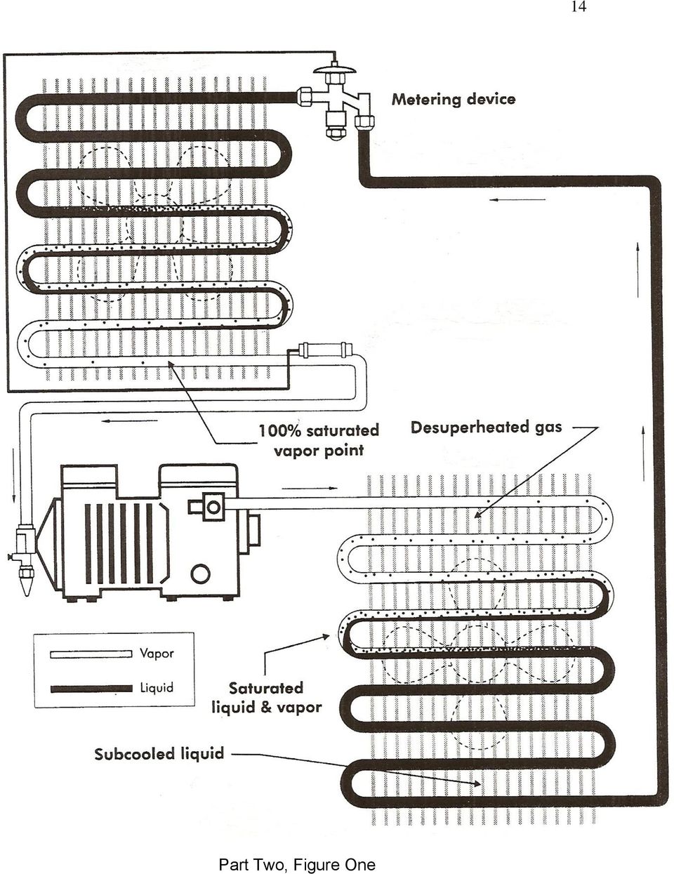
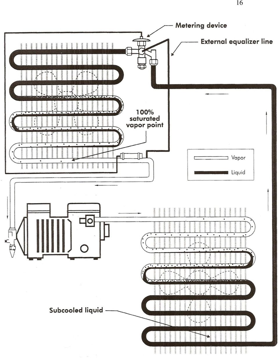
15 15 The simplest way to understand evaporator superheat measurements is to say that if you could place a thermistor or thermocouple device at the point we re identifying as the End of evaporator (which would be just a few inches away, and closer to the compressor, from the sensing bulb of the thermostatic expansion valve), we would be measuring the necessary temperature to calculate superheat. And, if we could install a Schrader Valve at this same point, we could, at the same time we re taking the temperature at the end of the evaporator, use our gauges to measure a pressure. With these two measurement accomplished, we could then effectively measure evaporator superheat. What s that you say? Installing a Schrader Valve at that point would be a great deal of work just to be able to take simultaneous and true pressure and temperature measurements? Well, we would agree with that. The idea of recovering the refrigerant from the system just to install an access valve, then evacuating and installing a new drier does seem like a lot of work just to be able to make a superheat evaluation. But there s another way.take a look at Figure Two. This illustration looks a lot like the one we showed in Figure One, but there is an important difference. Note the External Equalizer Line that runs from the body of the thermostatic expansion valve to a point just downstream of the TXV sensing bulb. If you re working on commercial refrigeration systems, it s a good bet that rather than an externally equalized valve system like the one we showed in Figure One, you ll find an externally equalized system being employed.

16 16
17 17 Consider the reasons an externally equalized valve would be required in a commercial refrigeration system: 1. Anytime there are distributors feeding an evaporator. 2. When the pressure drop in an evaporator causes a temperature drop of two degrees in coils that operate above 0-degrees F. 3. When the pressure drop in an evaporator causes a temperature drop of one degree in coils that operate below 0-degrees F. Or, to put it simply, the majority of commercial refrigeration systems, whether it s a walk-in cooler (large coil, needing a distribution tube into several inlets) or walk-in freezer (low-temp operation, large coil), or an ice machine (very low temperature coil), distribution tubes are employed. For a view of a typical multiple-distribution tube, externally equalized TXV installation, see Figure Three. Part Two, Figure Three What this drawing shows is that since the external equalizer line is connected directly to the suction line just a couple of inches downstream from the point at
 or walk-in freezer (low-temp")
18 18 which the sensing bulb of the valve is located, there is, essentially, going to be a connection directly to the refrigeration system at the very point we need to take a gauge reading. That being the case, it would be much simpler to install a Schrader Tee (maybe, as it often happens, one is already there check the system closely). Often, an external equalizer line is installed with a flare nut on the equalizer tube and a male flare fitting installed on the suction line itself. If this is the situation you find, then installing a tee (if it isn t already there) would involve the simple process of initiating a pumpdown of the system. Once the valve is installed and the external equalizer line is reconnected, allow the system to run for 10 to 15 minutes so it will reach equilibrium. Then, you can read your evaporator pressure at that point, while simultaneously taking a temperature reading. One other point to remember if you have a system with a long history of problems and you re planning on replacing the TXV, use an externally equalized one even if the original is an internally equalized model. It s OK to replace an internally equalized valve with an externally equalized one, though you can t make the switch-out the other way around. With all that said about being able to get a reading of both temperature and pressure at the proper location, let s look at an example: If you were working on an R-134a system on a walk-in cooler that showed an evaporator outlet temperature of 30-degrees F and a low side pressure reading of 20 PSIG, you could figure the superheat out by simply converting the pressure you read to a temperature. When consulting a temperature/pressure
 would involve the simple process of initiating a pumpdown of the system.")
19 19 chart (such as the one shown at the end of this handbook segment), you would find that a 20 PSIG reading would convert to a temperature of 23-degrees. Then, all you have to do is the simple arithmetic of subtracting 23 from 30, and you will have found that the evaporator temperature in our example was 7-degrees F. This is an interesting example to consider when understanding the evaporator superheat measurement process since one of the general rules of thumb is that when a commercial refrigeration system is operating with an evaporator coil temperature between 0 and 40-degrees F, the suggested superheat setting is 6 to 8-degrees F. When you put this factor together with the idea that you re trying to achieve approximately 40-degrees F box temperature in a walk-in cooler, and that means that the coil temperature would be approximately 15-degrees cooler than that (25-degrees F).and that converting 25-degrees to a pressure on an R-134a T/P chart would bring you relatively close to that 30-degree example we presented.well, you get the idea. This is a pretty common situation in walk-in coolers. What s that? Another question? What about that process of taking a pressure reading at the compressor, then factoring in a suction line pressure loss to compensate before converting your pressure to a temperature? Well, that process is fairly well-documented, and often used by technicians but it should be used only on air-conditioning systems, not on walk-in coolers and other commercial refrigeration equipment.

20 20 By the way, what often happens if a technician doesn t understand the idea of evaporator superheat (and they ve been told about the magic numbers of 6 to 8-degrees superheat), and they take a pressure reading at the compressor access valve instead of at the evaporator outlet? They get what is referred to as a fictitious superheat value. Due to pressure drop in the suction line, the same system we used as an example could have a pressure reading of near 15 PSIG. Which, when converted to a temperature would show up to be just about 15-degrees. And, with this converted temperature used in the simple arithmetic process, the false superheat calculation that would result would be 15-degrees which would mean that the technician, knowing the magic numbers of 6 to 8-degrees, might think that the adjustment of the TXV needs to be throttled down so as to drop the superheat to the correct level. Of course, the end result of all this is that the evaporator would wind up being starved for refrigerant, the efficiency of the refrigeration system would drop, and the compressor that depends on a cool suction gas would operate at a higher-than-normal temperature. So, the system would experience unnecessarily long run cycles and the life of the compressor would be shortened. All because of a false superheat calculation. The situation we just described sounds all too familiar.unfortunately, it s common to find this basic mistake being committed by a technician. But, it can be prevented by providing a simple training overview on the subject of evaporator superheat in a commercial refrigeration system. Coming up in Part Two, we ll look at the concept of total superheat and also subcooling.

21 Part Two, Figure Four 21
22 22 PART THREE TOTAL SUPERHEAT AND SUBCOOLING In the Part Two, our focus was on the very specific subject of Evaporator Superheat and what a technician needs to understand about it in order to properly evaluate (troubleshoot) a commercial refrigeration system. Beyond the issue of Evaporator Superheat is what s referred to as Total Superheat. A technician troubleshooting a commercial refrigeration system such as that found in a walk-in cooler or reach-in refrigerator needs to understand both types of superheat. And along with that, there s the subject of subcooling. We ll cover both subjects in this segment. Total superheat, which is often referred to as compressor superheat, differs from evaporator superheat in a very fundamental way. Total superheat is all the superheat on the low pressure side of the refrigeration system, beginning at the 100% total saturation point, and not ending until the suction line connection on the compressor. Evaporator superheat is measured only from the 100% saturation point in the evaporator (which is usually about 90% of the way through the coil) to the end of the evaporator, not including the suction line leading to the compressor. One way to think about total superheat coming into play on a TXV refrigeration system is in regard to the system operating on a light heat load, meaning that the TXV will lose control over maintaining the proper amount of evaporator superheat. This is something that could show up if you have a large capacity walk-in freezer, for example, that has a small amount of food stored in it.
23 Part Three, Figure One 23
24 24 Whatever the situation, measuring total superheat in a commercial refrigeration system can be accomplished. Then if necessary, adjusting the TXV is a straightforward process. To make sure you have a complete understanding of the total superheat concept, go back to Figure One and focus on the low pressure side of the system only. In the evaporator, you ll note the 100% saturation point shown very near the end of the coil. If you trace down from this point to a point on the suction line that would be, in reality about six inches away from the compressor, you re getting the picture of total superheat. And, the process of measuring this superheat is accomplished through two steps: One, is to take an accurate temperature measurement at the point about six inches away from the compressor. The reason you want to be careful about this point is that you don t want residual heat from the compressor skewing the information about the actual temperature of the suction line. The second step is to attach a gauge and get a pressure reading at the low side access valve on the compressor. Once you ve converted the pressure reading you got to a temperature by using a temperature/pressure chart, all that s required is to do the simple math and subtract the calculated temperature from the measured temperature to figure your superheat. One point we want to stress about this process is that of getting an accurate temperature reading of the suction line. Not only do you have to be careful about selecting the test point, you also need to prevent the influence of ambient temperatures on your reading. Holding a pocket thermometer up to the suction line to get as much contact as possible and then wrapping some Armaflex
25 25 insulation around the tubing isn t going to provide the information you need. For a small investment, you can get an accessory that connects to any good digital meter capable of reading temperature, and clamps on tightly to the suction line. With this type of sensing device you ll get an accurate temperature reading and without an accurate temperature reading, your superheat information will be incorrect. Here are some of the reasons you may get a lower-than-normal total superheat reading in a refrigeration system: 1. Dirty Coil. This is number one in the hit parade due to poor maintenance. 2. Low Air Flow Over The Coil. This one usually occurs due to an evaporator fan replacement in which the improper motor was used. So do some checking on the service history of the unit to find out if the not cooling enough complaint goes back to the last service call in which the evaporator fan motor was replaced. 3. Defrost Circuit Malfunction Causing Evaporator Icing: Something like a defrost termination thermostat kicking the heating element or hot gas defrost system off too soon could be the culprit here. Also, check to make sure that the defrost time on the timer mechanism is properly set. 4. End Of The Refrigeration Cycle: If the unit is about to shut off, you may experience a low superheat reading. 5. Low Refrigerant Charge: You ll note that we saved this one for last. The reason? This is the conclusion that most average service organizations jump to without even considering the first four causes we listed. The point
26 26 is check the other things before assuming a low charge. Most of the systems you check will be overcharged because many technicians don t consider the other four possible causes of lower-than-normal superheat. In most cases, manufacturers will prefer that their equipment operate with a minimum of 20-Degrees of total superheat, and, in general, that s a good rule of thumb to follow. Some manufacturers may even say that as superheat somewhere between 20 and 30 degrees is OK, as long as the unit is achieving its intended box temperature. However, if you measure a system that is experiencing, let s say 27-degrees of total superheat, and the complaint is not cooling enough you may have two tasks to accomplish. One would be to adjust the TXV back so the superheat drops closer to the 20-degree mark, then, doublecheck to make sure that the air flow over the coil is correct and that the system isn t overcharged because somebody didn t consider the other factors we mentioned in our list. SUBCOOLING Beyond the issue of superheat in a refrigeration system and determining whether or not the charge is correct, there s subcooling to consider. Like superheat, subcooling has two categories condenser subcooling and total subcooling. To understand either concept, consider where subcooling begins in a refrigeration system. (See Figure Two)
27 Part Three, Figure Two 27
28 28 Focusing this time on the high pressure side of the system, trace the discharge line from the compressor and note that the condition of the refrigerant is a vapor. As it proceeds through the condenser, it begins to change in state to a liquid, and there is a point at which the change is complete; where the refrigerant is now totally a liquid. It s at this point at which subcooling begins. It s commonly referred to as the 100% saturated liquid point in the condenser. To measure subcooling from a fundamental perspective, you need to follow the same kind of temperature and pressure measurement comparisons that apply to superheat. By taking a pressure measurement on the discharge of the compressor, then taking a temperature measurement at the end of the condenser, you ll have the two pieces of information you need, one of which has to be converted. Using T/P chart, convert the pressure reading from your gauge to a temperature, then subtract the temperature you read from that to calculate subcooling. Manufacturers often recommend that their equipment operate with a condenser subcooling of 10 degrees. Figure Three shows you the location to focus on when calculating condenser subcooling in a system. With a device capable of providing an accurate temperature reading, attach a sensor to the end of the condenser. In our example, we re showing a reading of 95-degrees.
29 Part Three, Figure Three 29
30 30 Another method of determining subcooling is known as total subcooling. In this situation, your temperature measurement isn t accomplished at a point near the end of the condenser coil, but instead a couple of inches away from the point of entry into the TXV. Figure Four shows you an illustration of measuring obtaining the temperature factor in a total subcooling measurement. Here are some numbers you can use as an example of calculating condenser subcooling: Let s say that you re working on an R-22 system and you ve measured the discharge pressure at 211 PSIG. Once you convert the pressure you read to a temperature, your condenser subcooling calculation would look like this: = 10 degrees If you consult a T/P chart like the one shown at the end of this segment, you ll note that at 211 PSIG, R-22 has a temperature of 105 degrees F. On smaller commercial refrigeration systems, focusing on condenser superheat is usually the best procedure to follow because when the total subcooling process is used, it sometimes gets complicated due to having to figure pressure drop into the equation. From an overall perspective, through, when understanding condenser subcooling and the superheat process we discussed in Parts 1 and 2, troubleshooting and servicing commercial refrigeration systems can be accomplished in a straightforward and efficient manner.
31 Part Three, Figure Four 31
32 Part Three, Figure Five 32
33 33 PART FOUR ALTERNATE EXPANSION DEVICES IN COMMERCIAL REFRIGERATION EQUIPMENT There s no doubt that the competent commercial refrigeration service technician needs a firm understanding of the standard TXV (Thermostatic Expansion Valve) since, after all, it s the most commonly used metering device in things like reach-in refrigerators, walk-in coolers and ice machines. Beyond the standard TXV though, are other metering devices that are used in specific applications. One example of this would be the AEV (Automatic Expansion Valve). Another example of an alternative metering device in commercial equipment and one that is growing in popularity.is the EEV (Electronic Expansion Valve). In this segment of Technical Update, we ll take a look at these two types of valves, and discuss how they re similar, yet different from, the TEV. We ll begin with an illustration of the Automatic Expansion Valve shown in Figure One. As you look at the details of this valve and its method of operation, one of the first things you notice is that it doesn t use a sensing bulb like a TEV does. (However, that doesn t mean that the AEV doesn t adjust to the heat load on the coil.more on that in a moment.) Instead, the valve uses an adjustment spring and screw assembly to regulate diaphragm pressure, and thereby regulate the flow of refrigerant into the evaporator coil. In our example here, we re showing the operating conditions for a typical R-12 system (yes, you ll still find a lot of older R-12 systems out there in this day and age) and the pressures you would
34 34 expect to find relative to the temperatures we ve listed. The situation we re presenting here, we ll describe as a normal load. Part Four, Figure One One of the key factors to understand about the AEV and how it adjusts for a heat load change is that it actually acts in reverse of a TEV. When the heat load on the coil goes up the suction pressure in the system begins to rise. This causes the AEV to throttle the refrigerant by closing enough to maintain the proper suction pressure (its set point). The end result of this action by the valve is that the coil is slightly starved for refrigerant. Figure Two shows you a slight increase in heat load on our system.
35 35 Part Four, Figure Two As you can see here, the temperature listings on the right side of the coil have changed as a result of the increase in air temperature from 50 to 55- degrees. But, it s important to note that in each case, the valve is, in fact, adjusted to maintain the 31 PSIG or 33-degrees shown in Figure One. The only real difference here is that the valve is responding to the increased air temperature, and will eventually, through the process of the throttling we described, handle that increase in load and get the pressure and temperature back where it needs to be. Likewise, in the event that the heat load over the coil drops, the AEV will react by opening up to increase the suction pressure up to the necessary level. (See Figure Three)
36 36 Part Four, Figure Three So while it s correct to say that the AEV operates in reverse of the TEV, and that s a difference between the two valves because while the AEV does modulate refrigerant flow but doesn t control superheat, it s also correct to say that there are similarities. Both valves allow more or less refrigerant into the evaporator in response to a load change, and they also both require a receiver to store the excess refrigerant when it s not needed due to a low load. As far as application of the AEV, it s best used in a situation where the load is somewhat constant, such as a water cooler. The main advantage of an AEV in this type of application is that it will prevent freezing while at the same time allowing the water to be chilled as cold as possible.
37 37 And now, a bit about the EEV. The electronic expansion valve is gaining popularity in many commercial refrigeration applications because it is more accurate at controlling refrigerant flow into the evaporator in response to a heat load change. The basic idea behind the valve and its controlling sensor is shown in Figure Four. Part Four, Figure Four As you can see here, the valve and sensor operate on a 24-volt control system that is created by a step-down transformer. The sensor itself is an NTC thermistor, which means that in response to a higher temperature, the resistance decreases, while in response to a lower temperature, the resistance increases. With the NTC thermistor wired in series with both a thermostat and bimetal/resistance heater-type valve, this refrigerant flow system can be stopped and sealed due to the closed valve when the thermostat is open. However, in a complete circuit, the thermistor can offer precise control of the valve body. This is due to the fact that the thermistor is very small in mass, and is not just attached
38 38 to a tube, but is positioned down inside of it. Figure Five shows you a valve that is responding to an increase in heat load. Part Four, Figure Five In this situation, you ll note that we re describing the process of vapor refrigerant coming in direct contact with the thermistor. The result of a vapor contact of the thermsitor is that its temperature goes up. And, in accordance with the fundamental concept behind an NTC device, the resistance of the thermistor goes down. In turn, this allows an increase in current flow through the 24-volt circuit to the valve. The increased current flow causes the valve to open up more and allow more refrigerant to enter the evaporator. This increase of refrigerant flow, in the same way that the increase of refrigerant flow from a mechanical TEV does, serves to handle the increase in load and keep the coil at its proper operating temperature. This is also accomplished in the event that the heat load drops. (See Figure Six)
39 39 Part Four, Figure Six In this situation, we re illustrating the concept that the heat load over the evaporator coil has dropped. In the case of either a reach-in refrigerator or walkin cooler or freezer, this occurs commonly when the cabinet door is not being opened frequently. With the drop in heat load, there will be a small amount of liquid refrigerant that begins to travel down the suction line. This is due to the fact that the refrigerant didn t have enough work to do and didn t all change from a liquid to a vapor in the evaporator coil. When the liquid refrigerant contacts the NTC thermistor (remember, it s quite small in mass so the refrigerant can handle it) it causes the temperature of the thermistor to go down. The end result of this drop in temperature is that the device increases in resistance, which means that there will be less current flow to the valve. This causes the valve to close down and decrease the amount of refrigerant flowing into the coil. And, once the decrease in refrigerant flow allows all the refrigerant in the coil to boil off, that means that vapor will once again be the condition of the refrigerant as it contacts the sensor. And, with vapor being the contact, the
40 40 temperature of the sensor goes up again, causing the valve to open up and allow more refrigerant flow into the evaporator. And, of course, what follows then, is that there will soon be liquid refrigerant contacting the sensor and cooling it down, which will cause it to increase in temperature and restrict the current flow to the valve so it will again throttle down to restrict the flow of refrigerant into the evaporator. The thing to remember about this modulation of refrigerant flow by the valve is that there is not a wide swing in temperature. The operation of the EEV system is constantly fine-tuning the adjustment of the refrigerant flow into the coil. The end result, as we mentioned earlier, is a more precise control system than that of a standard TEV. And, another advantage of the EEV over the TEV is that there are no problems with improper positioning of a sensing tube, nor is there a build-up of corrosion that will hinder the ability of the valve to get the message regarding a load change in the evaporator. All in all, the AEV and the EEV accomplish the same task as the standard TEV that you re used to seeing on commercial refrigerant equipment, but they get it done in a different way. Whatever the situation, a technician who has been afforded the opportunity to study the simplicity of the AEV and the technology of the EEV should have no problem troubleshooting and servicing a refrigeration system that uses them.
41 41 PART FIVE REPLACING A THERMOSTATIC EXPANSION VALVE In Parts 1,2, 3 and 4, our focus has been on the details regarding the operation and adjustments of TEV s AEV s and EEV s. In this segment, we re going to take things a short step beyond the idea of proper testing and adjustment. We say a short step, because replacement of a sealed system component that serves as a metering device is really just a short step beyond understanding how it operates and how to set it properly. However, in the commercial appliance arena, there have been countless instances of a poorly accomplished sealed system component, which always leads to a nightmare when it comes to correcting those situations. A quality service organization should always be prepared to inherit a situation in which your only viable option will be a major repair in regard to a metering device meaning replacement of the valve, either because an improper replacement was used, or the work wasn t done properly. As far as making sure you have the right valve for the job, if you can determine that the original in still in place, then this part of the service task is easy. If it s a Sporlan, Parker, or another manufacturer s valve that is Part #... whatever, all you have to do is look it up in the manufacturer s product listings and match your existing part number with either the same or replacement number that they recommend. Also, even if you re changing from one manufacturer to another due to an availability situation, you re often able to be
42 42 sure of an exact match because of cross-referencing material that is available to you. But, what if you re not sure whether or not the valve that s presently in place is the original, or the numbers you have just don t match up? Well, it s pretty simple. All you have do know is some basic facts about your equipment to make the right choice. You need to know. 1. The BTU capacity of the system. 2. The type of refrigerant used. 3. The evaporator temperature. 4. The pressure drop across the valve. 5. The liquid temperature entering the valve. At first blush, the list above may give you pause because it looks like some of those factors are things that are engineers are supposed to deal with, not technicians. However, they re simple facts that can be understood with a simple approach to research and understanding of the refrigeration system you re servicing. In regard the #1, this is simply the tonnage rating of the system. Often the best place to look for this information is on the condensing unit of the system. The BTU/hr capacity of the unit will often be one of the pieces of information on the equipment tag, along with the second factor you need to know.which refrigerant is being used. We need to say that often, this information isn t going to be easy to come by. You may need to spend a fair amount of time just accessing
43 43 the condensing unit so you can get a look at the equipment tag, and when you do find it, you may wind up practically standing on your head with your Mag Lite, trying to see past the dirt and grime to find the information you need. But, as we ve said, these are the kinds of things that set a quality service organization apart from the average service company. Remembering the simple rule that there are 12,000 BTU s in one ton of refrigeration capacity is your first step in identifying which thermostatic expansion valve you ll need for a system. Manufacturers such as Sporlan or Parker provide selection tables of their replacement valves that list their products by tonnage ratings. In smaller systems such as a reach-in refrigerator, you may need a valve that is rated only for 6,000 BTU s (One-half Ton) or even a 3,000 BTU (Onequarter Ton) of capacity. Another factor to keep in mind here about the refrigerant in the system is that you may want to use this service opportunity to use a replacement refrigerant. Since one of the things you would have to do to convert a system is to use a different expansion valve anyway, consider the idea of making the conversion to a refrigerant that will be a better fit for your customer. If it s a system that s using R-12 for example, or if it s one of those blends that were the only thing available at the time as a replacement, the equipment is a good candidate for a complete changeover. With the first two factors considered, we can move on to the third on our list, which is understanding evaporator temperature. There are a couple of ways you can approach this information. The first is to understand the simple rule that in a
44 44 walk-in or reach in unit, the actual coil temperature will be approximately 15- degrees cooler than the design temperature of the box. So, as an example, if you know that you re working with a walk-in cooler that is supposed to maintain 40- degrees, then your actual coil temperature is going to be 25-degrees. Another way to approach this is to recall some of the simple facts about lowpressure controls in commercial refrigeration systems. Since it s common to find this type of control used as a temperature control system, consulting the cut-in and cut-out temperature settings can give you a fair amount of information about the evaporator temperature. Figure One shows you some low-pressure control settings for a variety of refrigerants. Part Five, Figure One With an understanding of cut-in and cut-out temperatures, you only need to consult a temperature/pressure chart to accomplish the conversion you need.
45 45 Remember, a T/P chart can be used on two ways: First it can tell you what your refrigerant pressure will be at a give temperature, and second, it will tell you what your temperature will be when your refrigerant is at a certain pressure. So, consult any available information regarding the low-pressure control and consult a T/P chart to figure out what your coil temperature is likely to be. Once you have this fundamental information in hand, you can begin your search for the proper replacement valve in a manufacturer s catalog, which is where you ll begin to find the other information necessary regarding pressure drop and liquid temperatures entering the valve. Another point to understand while consulting manufacturer s information is the correct power element. The power element section of the TEV is the sensing bulb section, and manufacturers will provide you with information relative to the kind of charge in the bulb whether it s a combination of liquid and vapor or liquid only. And, with the information about the bulb charge and the five factors we listed previously covered, you can begin the repair while keeping other things you need to consider in mind. There s the idea of positioning the valve to think about. In some cases, it may require some piping changes in order to be sure that the installation won t be harder than it should be due to the routing of tubing etc And, you also need to be sure that the type of valve equalization in a match. If the original design called for a valve that is internally equalized, then an internally-equalized valve should be used. If the original equipment was equipped with an externally equalized system, then a valve that has an external equalizer port must be used.
46 46 By the way, you can tell if the person who was there ahead of you and replaced a TEV but didn t do it right because they didn t understand the idea of internal vs. external equalization systems. Sometimes, believe it or not, they ll install an externally equalized valve in an internally equalized system and simply cap off the external equalization port on the valve. Or, they ll ignore the externally equalization requirement for a system by installing an internally equalized valve and simply getting rid of the external equalized tube. In either case, their approach is very wrong. So, when you re in the position of coming along behind a service company that didn t do satisfactory work, look for signs of these incorrect modifications. (For more information on the difference between internally and externally TEV s review the information we covered earlier where we described the fundamental operation of a TEV.) To complete your installation, you may need to consider some fundamental safety issues regarding brazing. It s a good idea to wrap the valve in a heat-absorbing material while you solder the fitting connections. And, in consideration of the installation of the sensing bulb, follow the general rule of avoiding placing it on the bottom of the tube. In many cases, manufacturers recommend that the best position for the sensing bulb on piping that is 7/8 or larger is at the 4 or 8 O clock position. On smaller tubes, positioning the sensing bulb on either side is the best rule to follow. And the last consideration for the sensing bulb is to be sure that you use two clamps to make sure that there will be good thermal contact between the bulb and tubing. Once you ve followed the
47 47 steps to make sure you re using the proper valve and have followed good installation procedures, allowing the system to run for 15-minutes or so before adjusting the superheat is a good rule of thumb to follow.
48 48 PART SIX MISUNDERSTOOD DEVICES IN COMMERCIAL REFRIGERATION SYSTEMS Now that we ve provided information on the fundamentals of commercial refrigeration equipment operation, we ll move on to discussing some of the system accessories that are used. No doubt, there a quite a few more devices to understand in, say, the refrigeration system of a walk-in cooler as opposed to that of a domestic refrigerator or room air conditioner. But, taking a proactive approach to understanding system accessories can make the entire system easier to understand. With that thought in mind, we ll discuss a few of those refrigeration system accessories that can sometimes be a source of confusion for technicians. We ll begin with a suction line accumulator such as the one we re showing in Figure One. Like any refrigeration system, the compressor in a commercial piece of equipment is designed to pump vapor, not liquid. And in a perfect world, that s all that would ever get into the suction line of the refrigeration system, causing the compressor to be protected from liquid slugging. However, there are such things as a dirty evaporator coil that would prevent the refrigerant from changing totally from a liquid to a vapor, and when that happens we need to protect the compressor. An accumulator is, in essence, nothing more than a storage tank on the low-pressure side of the system. Domestic refrigerator evaporators have them, and they appear as a segment of the evaporator. Room air conditioners also have them, but they appear as a separate item in the piping of the suction
49 49 line. The room A/C accumulator appears more like those that you ll find in commercial refrigeration systems, but there s still another step up. Part Six, Figure One As you can see in our illustration, in addition to the flow of refrigerant into the accumulator and an outlet at the top showing vapor flow to the compressor, there are a couple of additions to this particular example. Note that there is what s referred to as a heater coil wrapped around the body of the accumulator and that the condition of the refrigerant is this coil is identified as Hot Gas. The place where the Hot Gas comes from, of course, is
50 50 from the condenser of the system. In commercial applications, manufacturers often allow a pass of the discharge line of the compressor to be fastened to the accumulator body. This heat exchanger (much like the heat exchanger that is made up of the capillary tube fastened to the suction line in a domestic refrigerator) ensures that any liquid refrigerant in the suction line will have some work to do because of the heat being introduced, and completely change in state to a vapor. Another feature found on commercial equipment accumulators but not on domestic systems such as room A/C s is the oil return line located at the bottom of the accumulator. Remember, in any refrigeration system there is a certain amount of oil that travels with the refrigerant, and in commercial equipment, this is going to be a higher volume of oil found traveling in a refrigerator or freezer. Because of that, commercial refrigeration system suction accumulators are often equipped with an oil return line that allows easy flow of oil back into the crankcase of the compressor. Getting it directly into the crankcase is much more efficient that trying to get oil to flow into the suction side of the compressor, then be dealt with through the suction valves in a piston compressor or the rotary vane of a rotary-type compressor. And now on to another misunderstood accessory, the receiver. In some of the smaller refrigeration systems such as those in reach-in refrigerators or soda vending machines, the receiver will have an inlet at the top and an outlet at the bottom. In larger units, however, the receiver can appear
51 51 differently because is uses a dip tube design, such as the one we re showing in Figure Two. Part Six, Figure Two In this illustration, we re showing the receiver in a horizontal position, which is a common method of positioning by some manufacturers. In some cases, however, the receiver isn t horizontal, instead it s a vertical mount, such as we re showing in Figure Three. Whatever the position, the purpose of the receiver is to act as a storage tank on the high-pressure side of the system. In TXV systems, for example, we have to put that extra refrigerant that we re not using in a low heat load situation somewhere, and the somewhere is the receiver. Another use of the receiver on a commercial refrigeration system is to allow an automatic system pumpdown or for a manual pumpdown of refrigerant during a service procedure.
52 52 Part Six, Figure Three One other variable you might see relative to receivers in commercial equipment is that they may be equipped with a sight glass so you can check the liquid refrigerant level. And speaking of sight glasses, we re showing a typical one in Figure Four. Before blended refrigerants that have a tendency to show their bubble point in the liquid line of the refrigeration system, the general wisdom regarding this accessory was that you should never see any bubbles at all in it, and if you did, it meant that the refrigeration system was undercharged and needed some gas. Well, we ve talked about service organizations that jump to the conclusion
53 53 that every time a walk-in, reach-in or ice machine isn t working right, the answer is to dump in some gas. Not always true. Part Six, Figure Four In a situation in which there is a high heat load on a system, you ll likely see bubbles in the sight glass on an initial start-up and probably even for several minutes after that. Also, a restriction in the liquid line before the sight glass is sure to create bubbles. And, since a sight glass is often used in conjunction with a filter-drier on the liquid line (which can become restricted with contaminants) a restricted system is sometimes mis-diagnosed as a system undercharge, when in fact, the solution to the problem is to solve the restriction situation. When a technician overcharges a system with a receiver to a certain extent, the only indication is a slightly higher-than normal pressure on both the high and low pressure sides of the system. In severe overcharge situations,
54 54 however, the entire receiver can be full of liquid. The bottom line on this situation is that if a technician understands the concepts of superheat and subcooling we discussed in previous segments, then they won t be mis-lead by bubbles in the sight glass and jump to the conclusion that they have to add refrigerant. Another situation in which bubbles can occur in the sight glass is in the event of a sudden change in heat load in the middle of a cycle. Bringing in a shipment of food products that need to be frozen or chilled and loading them into a walk-in or display case is a good example of this situation. You also need to consider the possibility that there has been a change in a head pressure control system that could dump hot gas into the receiver to build head pressure up to a point where it s supposed to be. One example of this would be a low ambient control system on a condenser fan motor. If the condensing unit is located outside in a cold temperature, the low ambient control would break the circuit to the condenser fan motor to ensure that the high side pressure would stay up where it s supposed to, maintaining a proper differential between the high and low pressure sides of the system. (After all, if the high pressure and low-pressure side of a refrigeration system are too close together, then the refrigeration process won t be accomplished.) At the beginning of this head pressure rise due to stopping the condenser fan motor, there may be bubbles in the sight glass. And, of course another use for the sight glass is to check on the possibility that there is moisture in the system. Manufacturers use a variety of colors to determine if a system is wet or dry (green, yellow, etc ) so you need to check the color code on the sight glass itself to determine whether or not there is
55 55 moisture in the system. This can be difficult in older systems since the colors printed on the sight glass body tend to fade. In the event that you can t determine whether or not there is moisture in the system, monitor the high side pressure closely. If, without the introduction of any heat load changes, the high side pressure tends to fluctuate, that would be an indicator of non-condensibles in a system. And, if there are non-condensibles (air) in a system, that means that there is also moisture present. This situation usually occurs due to improper service procedures in which the technician doesn t take the time to purge the hoses on their gauge set before adding refrigerant (which they likely didn t have to add in the first place), and the end result is the introduction of noncondensibles into the system along with the added refrigerant. In a situation like this, your only quality service solution is to recover the refrigerant, install a new filter-drier on the liquid line and also add a drier on the suction line, evacuate to a proper level using a micron gauge and re-charge the system.
56 56 PART SEVEN MORE ON MISUNDERSTOOD DEVICES IN COMMERCIAL REFRIGERATION SYSTEMS In Part Six, our focus was on a few of the common refrigeration system accessories found in commercial equipment such as walk-in s reach-in s or display cases. In this segment, we ll pick up where we left off by talking about commercial equipment filter-driers. It s more common to find a filter-drier on both the liquid line and suction line in commercial systems. This is largely due to the fact that there are more sealed system repairs done in the commercial arena.major repairs that are the result of a compressor burnout.which is the reason the suction line filter-drier shows up more often. As far as the basic construction of either one, Figure One shows you what they look like on the inside. Part Seven, Figure One
57 57 One thing you ll note about this illustration is that it shows an arrow that points out the direction of flow through the drier assembly. This is a simple, yet very important point to remember about any filter-drier. When the refrigerant enters the assembly in the proper direction, it is allowed to free-flow through before being forced through a more dense material at the outlet side of the drier. If, however, the drier is installed backwards, the refrigerant hits the more dense material first, and the result is a restriction of flow. Of course, if you restrict the flow of refrigerant in any way, then provide an area for free flow, what you re simulating is a metering device of some sort, then a kind-of evaporator. Which means that a filter-drier that is installed backwards will be acting like a little evaporator.cool to the touch, or maybe even frosting a bit. (By the way, from a troubleshooting perspective, if a liquid line drier starts to fill up with moisture and debris, it will also be cool to the touch because it is restricting refrigerant flow, so keep that in mind too. The drier doesn t just have to be installed backwards to show the cool to the touch restriction problem.) And, now on to the suction line filter drier. In order for you to get an understanding of how it compares to a liquid line filter-drier, we re showing both of them in Figure Two. The one on the left is the suction line drier, and you ll note when you look closely that it has two service ports on it that allow you to connect your gauges. Unfortunately, many service technicians see these service ports as nothing more than a convenient place to connect their gauges so they can dump in some gas while servicing the system. Well, that s not how an above-average service
58 58 organization looks upon these two connections on the suction line drier. They know that the two ports are there so they can check for pressure drop across the drier. Part Seven, Figure Two Here s the simple story on suction line driers Most often, a suction line filter-drier is installed on a system in the event of a major repair, such as a compressor burnout. The reason for the addition of the suction line drier is to filter the vapor refrigerant and catch an acid that may be remaining, along with any solids. When the repair is first accomplished, the flow through the drier should be without restriction. However, soon after the system has operated for a while, the suction line drier, depending on how much acid and other contaminants are in the system, can begin to clog up. How do you know? By checking first on the inlet side of the drier for an operating pressure, then
59 59 check on the outlet side of the drier. If the pressure drop is less than 2 PSIG, then the flow through the drier is OK. If, however, you get a pressure drop of more than 2 PSIG, it s time to shut the system down, isolate the compressor, recover all the refrigerant, and install a new set of filter driers. The reasoning behind this is that the suction line drier is doing exactly what you expect it to do catch contaminants and protect the new compressor. If the pressure drop becomes too great, however, the refrigerant flow to the new compressor will be compromised. Remember, in any vapor compression system that uses a piston compressor, the compressor depends on a free flow of cool refrigerant coming back down the suction line to help keep it cool. If that flow is restricted, then the overall temperature and discharge temperature of the compressor will be higher than normal, leading to a repeat compressor failure in the equipment. MUFFLERS. A muffler is another accessory you ll see on commercial refrigeration systems. If you re familiar with room A/C refrigeration system servicing, you ve seen some version of one. Figure Three shows you the type commonly found on commercial equipment. Like the muffler you may have seen on room air conditioners, this type is commonly found on the discharge line of the compressor, and it serves the same purpose as the ones used on domestic systems to reduce compressor noise. However, on commercial equipment, there s one more caveat to keep in mind. In
60 60 some cases, if a system is large, it may have a muffler on the suction side of the compressor as well. Sometimes mistaken for a suction line filter-drier without access valves, it will be located fairly close to the compressor. Part Seven, Figure Three CRANKCASE HEATERS. If you ve had any experience with servicing heat pump systems in residential or light commercial applications, you ve likely seen a crankcase heater. It s an accessory that is designed to keep a compressor crankcase warm in order to prevent the migration of liquid refrigerant into the compressor on an off cycle. So, what that means is that whenever the compressor is off, the crankcase heater should be on. Figure Four shows you a situation in which a hermetic compressor is fitted with an external crankcase heater. Other situations in which you ll find an external crankcase heater (in both hermetic and semi-hermetic compressors) is when the condensing unit of the refrigeration system for the walk-in, ice machine, reach-in, or whatever, is located
61 61 in a cold environment such as just outside the kitchen. Another factor to keep in mind about crankcase heaters is that they can be in the form of something other than an external mount. In some cases (such as newer equipment), the crankcase heater is an integral part of the compressor assembly. Part Seven, Figure Four In a well that is built into the compressor, the crankcase heater is inserted and the wiring is the only thing showing exiting the compressor case. Which means that if you re replacing a compressor with an external heater with one that has an internal heater, all you have to do is hook up the appropriate wiring so the new heater will operate in the same way the original one did.
62 62 And, when it comes to the wiring of a crankcase heater system, a transformer is sometimes used to control its operation. Figure Five shows you a simplified schematic of a crankcase heater control system. Part Seven, Figure Five In this segmented diagram, we re showing the compressor, along with an accompanying outdoor fan motor, and we re controlling the operation of both components with a set of normally open contact points. On the secondary side of the step-down transformer symbol that makes up the body of the diagram itself, we re showing the symbol for a contactor coil, which is controlled by a simple switch. In most cases, this switch is a temperature-controlled device (like a simple thermostat on a refrigerator) that calls for cooling.
63 63 On a call for cooling the switch is closed, providing a 24-volt circuit to the contactor coil. When the coil is energized, the normally open contact points close and compressor and condenser fan motor operate. But, the real story behind this diagram is what happens when the temperature-operated switch in the system is satisfied and the compressor and condenser fan motor turn off. Another set of contact points (shown as C3 on the diagram) are identified as being normally closed. And, you ll note that they are wired in series with a component identified as CCH, which will be energized in an off-cycle, but then de-energized when the compressor is operating. This is the most common method of controlling the crankcase heater in a commercial refrigeration system. However, in some situations in newer equipment, there may be some reason the manufacturer has chosen to keep the crankcase heater on when the compressor is running below a certain operating temperature. In these cases, you ll likely find a thermistor and printed circuit board type of control system that tells the crankcase heater when to be on and off.
64 64 PART EIGHT STILL MORE MISUNDERSTOOD DEVICES IN COMMERCIAL REFRIGERATION SYSTEMS In the last two segments, we discussed refrigeration system accumulators and receivers, sight glasses, suction and liquid line filter-driers, and crankcase heaters. Quite an extensive list of refrigeration system accessories, but there are a few more to cover. In this segment, we ll discuss two types of valves that are designed to control the refrigeration system pressures in the event of a temperature changes. One of these is the EPR Valve, and the other is the CPR Valve. First, the Evaporator Pressure Regulator Valve. The EPR valve is located on the suction line of the refrigeration system and refrigerant flows into it from the evaporator, then on into the compressor. The basic idea behind the operation of the EPR valve is to modulate the flow of refrigerant, thereby maintaining the correct pressure in the evaporator. As you know, temperatures affect refrigeration pressures, and if the temperature of a coil goes too low, then the pressure of the system could also drop to a lower-thandesired level. Figure One shows you an illustration of the EPR valve. One of the applications of an EPR valve is a chilled water system, which you won t see much of in restaurant equipment, but it helps to know this so you can gain a full understanding of the operation of the device. In a chilled water system, the critical factor is to prevent freeze-up, so a drop in coil temperature below a certain level is a critical factor in the proper operation of the system. So,
65 65 the EPR Valve, since it s piped in series with the refrigerant flow from the evaporator, can sense a drop in pressure, then adjust to slow the flow of refrigerant, which in turn keeps the pressure in the evaporator up to a proper level. All of which, as we said, keeps the evaporator temperature correct. Part Eight, Figure One In some cases, you may find an EPR valve referred to as a hold-back valve since that is what it really does. holds back the flow of refrigerant. The basic design of the valve is that it consists of a bellows that is regulated by a spring pressure (adjustable. In the event that the pressure in the evaporator
66 66 drops below what it s supposed to be, the spring pressure serves to control the position of a seat disk, allowing either an increase of decrease in refrigerant flow. This is often critical during a start-up of a refrigeration system. When there is a high heat load on a start-up, the valve will remain wide open to allow maximum refrigerant flow, then will modulate down slightly when necessary as the heat load drops, and it will maintain the lower rate of flow until the system cycles off. On a new cycle, the valve will again open wide to allow maximum flow. If you find yourself working on a commercial refrigeration system that has multiple evaporator coils, it s likely that you ll see EPR Valves in use. Figure Two gives you an illustration of this application. Let s say that you re dealing with a combination walk-in cooler/freezer (sort of like a great big domestic refrigerator) that has to maintain a 40-degree environment for things like vegetables, but in the freezer section, it needs to be near zero for ice cream, etc In that situation, you will often find two different evaporator coils, one compressor, and one refrigerant being metered to both coils in order to accomplish the refrigeration process. Common sense tells us that in order to maintain these two very different cabinet temperatures, the coil temperatures will be different, which would result in different coil temperatures. And, this would be a problem for the refrigeration system overall because the refrigerant would have a tendency to migrate to the lower-pressure coil, starving the higher-pressure one. The solution, is to use an EPR Valve on each of the coils in the system. (Our illustration shows four separate coils, but the same concept applies to only two coils.)
67 67 Part Eight, Figure Two As you can see, no matter what the varying pressures would be on the individual coils, the suction line pressure leading back to the compressor is always going to be maintained at 15 PSIG. This would be the case no matter what the individual evaporator pressure would be, either above or below 15 PSIG.
68 68 When adjusting an EPR Valve, you need to know what the design temperature of the cabinet is supposed to be, then apply the rule of thumb that the actual coil temperature would be 15-degrees cooler than that number. For example, if you had a coil in a cabinet that was supposed to be 40-degrees, then the actual coil temperature would be 25-degrees. That would mean you could use a temperature/pressure chart to plot what the refrigerant pressure was supposed to be, put your gauges on the system while it was operating, then adjust the spring pressure in the valve until the evaporator coil pressure was correct. In most cases, this process is accomplished (and doesn t need to be modified) at the time the system is installed. The problem, though, is that sometimes, an average service organization doesn t know that they re supposed to leave the EPR valve alone, and they try adjusting it to solve a complaint of not cooling enough.when in reality the complaint is related to something simple like a dirty condenser coil. So keep in mind that if you re following up on previous unsatisfactory service by another company, look closely to see if the EPR valves have been tampered with. And, now, on to the CPR (Crankcase Pressure Regulator) Valve. This valve, shown in Figure Three, looks very similar to the EPR valve. Like an EPR Valve, it has a means to adjust a spring pressure and control the flow of refrigerant through an opening, and it also has an inlet and an outlet. Look closely, though at the indicators that show the path of refrigerant flow, and you can see that when it s piped into a system, it can be identified as a CPR Valve. While both valves are located on the suction line of the refrigeration system, their
69 69 inlet and outlet piping connections are reversed. And another tip-off that you re looking at a CPR Valve rather than EPR Valve is that it s going to be located closer to the compressor. In the situation in which an EPR Valve is used, it is located much closer to the evaporator coil. Part Eight, Figure Three The function of a CPR Valve differs from an EPR in that its job is to protect the compressor in the event of what s known as a hot pull-down. For example, if
70 70 a customer loads a reach-in with a lot of hot product, then there will be a severe heat load on the system until that product is cooled down. In these situations, the refrigerant returning to the compressor will be much more dense than under normal operating conditions. And, since a refrigeration system compressor is a constant volume pump, it won t know it is being overloaded, and the end result could be a higher-than-normal current draw. Figure Four shows you an illustration of a hot pulldown and what the CPR Valve is designed to do. Part Eight, Figure Four
71 71 In this situation, we re showing a box that is experience a higher-thannormal return air temperature, which is causing the low-side pressure to be higher than it should be. For example, if this was a low-temperature display case for frozen items, the return air temperature would likely be near 10-degrees, which wouldn t have an effect on the pressure. However, with our high heat load, the low side pressure is way up, and could cause the compressor to run for an extended period of time at an amperage draw that could damage it. The answer is the CPR Valve. With the valve adjusted to throttle the higher pressure in the suction line, the actual pressure of the refrigerant delivered to the compressor will be lower, and the end result will be a normal current draw. Which means, of course, that in order to adjust a CPR Valve, you re not going to be using your gauges this time, only a clamp-on ammeter. To begin either that adjustment process, or to check the operation of this valve during a preventative maintenance procedure, determine what the current draw of the compressor is supposed to be by checking the compressor tag or the equipment manufacturer s equipment manual. Keep in mind that the compressor should not operate at a current draw of more than 10% of its rated capacity during a hot pull-down. For example, if the rated current draw of the compressor was 20 amps, then you should not be exceeding 22 amps under a higher-thannormal heat load in the box. If you experience a current draw of more than 10%, adjust the valve until your ammeter shows a safe level.
72 72 Understanding this process and the operation of the CPR valve is an important factor in advising your commercial customer about the value of preventive maintenance. In the event that a CPR Valve is not adjusted properly, the end result could be a compressor failure. Often, in situations in which your customer tells you that they have had more than one compressor replacement in a piece of equipment, check to make sure the CPR Valve is properly adjusted.
73 73 PART NINE THE FUNDAMENTALS OF COMMERCIAL REFRIGERATION EQUIPMENT ELECTRICAL SYSTEMS Up until now, our focus has been on the fundamentals of commercial refrigeration systems and some of the commonly misunderstood devices (accessories, actually) that are used to maximize the cooling capacity of things such as walk-in coolers and freezers, reach-ins, or ice machines. And our point in discussing those devices was that, since they are commonly misunderstood, technicians often mis-diagnose problems with commercial refrigeration systems and wind up replacing parts that don t need replacing. Well, the problem of misdiagnosis and unnecessary part replacement isn t limited to the refrigeration side of commercial equipment servicing. Electrical mis-diagnosis is just as common, and the underlying reason for it is the same as it is for refrigeration system service error.a misunderstanding of how certain devices are supposed to work. So, the question is, how does an above-average service organization approach this problem? It s simple, really.they make sure the technicians faced with this challenge have the tools they need to avoid those misdiagnoses. And the place to begin providing those tools is with a simplified schematic diagram, such as the one we re showing in Figure One. In this illustration, we ve simplified a typical diagram for a walk-in cooler that uses a remote condensing unit. In the process of simplifying it, we re showing only the motors themselves with no special start devices or capacitors, and we re showing a simplified control system that is electrical in nature.
74 74 Part Nine, Figure One In many cases, pressure-sensing devices are used to control commercial refrigeration systems, and we ll get to those but first we ll focus on the electrically-controlled system in order to make it as easy as possible for technicians who are used to seeing thermostats on things like domestic refrigerators and freezers. Starting at the top of the diagram, we ll explain the symbols and labeling.
75 75 1. First, in understanding any electrical system, the power source must be identified because that is the basis for tracing all electrical circuits, and ultimately accomplishing troubleshooting and diagnosis. The identifiers L1 and L2 represent the fact that this is a 240-volt single-phase power supply. We know it s not a 120-volt system, which would have either shown L1 and N as the identifiers, or would have indicated the voltage as being 120 in the labeling. 2. CFM, shown in a circle represents the Condenser Fan Motor. In most cases, this type of motor is a PSC-type, meaning it uses a run capacitor wired in series with the start winding (yes, we said that right, it s not a typo we ll get more into that detail later) in order to promote a more efficient operation. But, as we mentioned, we re simplifying this diagram as much as possible to explain the fundamental components. 3. COMP which is shown directly below the condenser fan motor, is, of course, the system compressor. Since we have a bit more space with this symbol, we re showing some of the actual electrical construction of a motor by representing the windings within the circle. Either type of symbol, lettering only inside a circle or schematic symbols, are standard industry practices for identifying components.
76 76 4. On the top line of our ladder diagram you ll see the identifiers C1 and C2 which represent one segment of a contactor. These normally open contact points will only close when the other segment of the contactor (which we ll discuss shortly) is energized. These are the types of contact points that will become blackened with a carbon build-up due to arcing. Often, inexperienced technicians note the pitting and discoloration and think that they need to file the contact points in order to promote a good connection when they close. And, when they take this approach to preventive maintenance, they wind up ruining a contactor. The contact points are coated with a silver or silver oxide material that is designed to carry electrical current without sustaining damage. But, that doesn t mean that the material won t discolor. And, what the filing does is actually scrape off the thin silver surface, which shortens the life of a contactor. So the rule here is don t file the contact points, but if they re damaged to the point where they re pitted, the contactor needs to be replaced. 5. The EFM is the evaporator fan motor located inside the walk-in cooler cabinet. Up till now, we ve been describing components that are located on the roof or near the building on the ground, but with this symbol, we ve moved into the cabinet. Like condenser fan motors, this one is also usually a PSC motor.
77 77 6. On the same line with the evaporator fan motor, and wired in series with it, you ll note a set of normally open contact points, labeled R1. This represents one segment of a relay that is used to control the operation of the evaporator fan motor. Like the contactor, there s another segment to this relay that we ll discuss shortly. The relay itself is likely going to be located in a control box found on the side of the walk-in cabinet. 7. CCH is shown on the next line down on our ladder, and with this symbol we ve moved back outside the building. This symbol and identifier represents a crankcase heater that is either attached to or integrated into the compressor. The purpose of this device, as its name indicates, is to keep the compressor crankcase warm. With the compressor sitting outside, refrigerant can migrate to the crankcase in lower ambient temperature situation when the compressor is cycled off. Which would mean that there would be liquid refrigerant sitting in the compressor crankcase that, on start-up, would cause the oil in the crankcase to foam. To prevent this bearing lubrication problem, the crankcase heater is used to keep the compressor temperature up, thereby preventing the migration of refrigerant. 8. C3 is shown wired in series with the crankcase heater, and you ll note that these are normally closed contact points. Another segment of the contactor, these contact points will remain closed until the contactor coil is energized. So, what we ve identified so far in regard to our contactor is that two sets of
78 78 contact points (C1 and C2) are normally open and one set (C3) is normally closed. 9. The transformer symbol is next. As the heart of the dual-voltage schematic diagram, one winding is shown connected to the L1 and L2 power supply, and a second winding is shown as being a power supply. That s why we refer to it as a step-down transformer. While 240-volts is applied to the primary winding, 24-volts is being created to provide the control circuitry that involves the components shown in the lower segment of the diagram. 10. The letter R shown in a circle is next, and it represents the coil of the control relay, whose contact points are wired in series with the evaporator fan motor and shown on the upper segment of the diagram. There s a correlation between the R shown in the circle below and the R1 contact points. Even though these two identifiers are shown far apart, they represent one component.the evaporator fan relay. With 24-volts applied to the relay coil, the contact points will close and the circuit to the evaporator fan motor will be complete. 11. The letter C is shown below on the next line and it represents the contactor coil. With the coil energized with the 24-volt control voltage in this electrical system, two things will happen. First, the normally closed contacts wired in series with the crankcase heater will open, and second, the normally open
79 79 contact points will close, creating a complete circuit to both the compressor and condenser fan motor. Like our evaporator fan relay, even though the identifiers are shown far apart on the diagram, they represent one component. 12. Of course, what we described in 10 and 11 takes place due to the operation of the thermostat, which is also shown on the lower segment of our diagram. On a call for cooling the thermostat closes, completing the circuit to the coils, which turns off the crankcase heater while at the same time turning on the compressor, condenser fan motor and evaporator fan motor. And, what we ve proven with this brief review of the fundamentals of a schematic diagram is that servicing commercial refrigeration system electrical components is no more complicated that servicing domestic appliances. And we ll continue simplifying and uncomplicating the process of troubleshooting electrical systems in commercial equipment in the next segment.
80 80 PART TEN DETAILS ON THE FUNDAMENTALS OF COMMERCIAL REFRIGERATION ELECTRICAL COMPONENTS In Part Nine, we walked through a simplified schematic diagram in a stepby-step process. The idea of that exercise was to begin to lay a foundation for the development of electrical troubleshooting skills. Another element of that foundation is understanding the specific facts about electrical components such as relays, contactors, bimetal switches and pressure switches.some of the things a technician has to deal with when servicing commercial refrigeration equipment. To get us started on this foundation element, we ll look at a couple of different types of relays you may find in a piece of commercial equipment, and a contactor, all of which we re showing in Figure One. In this illustration, we re showing a picture of the components as they appear, as well as an electrical illustration of them so we can explain how they operate. First, let s consider the relay shown at the left of the illustration.
81 81 Part Ten, Figure One This is the simplest type of relay you ll see on commercial equipment and it can be used for a variety of tasks such as operating a fan motor or controlling a circuit to a solenoid valve. We say it s the simplest type of relay because it only contains one set of normally closed (N.C.) contacts and one set of normally open (N.O.) contacts. Which means that any circuit that is introduced at terminal #1, will leave either on terminal #2 or #3, depending on what is going on with the relay coil at the moment. The coil, which is often operated on a step-down voltage circuit (although it may also be operated on line voltage) is shown without any terminal markings. In some cases this may be the case, while in other cases, a particular relay manufacturer may assign numbers to the coil connections also.
82 82 Whatever the case, troubleshooting this type of relay is fundamentally nothing more than using an ohmmeter to check three things: 1. Resistance of the coil. 2. Continuity between 1 and 3 when there is no voltage applied to the coil. 3. Continuity between 1 and 2 when there is voltage applied to the coil. We want to point out that we were very specific in using the terms resistance and continuity. While some technicians lump the two terms together under the same definition, they are two very different concepts. When checking a load something that does work when electrical energy is applied to it the term resistance applies. When checking a switch.something that does no work but either allows or interrupts current flow in a circuit the term continuity applies. Which means that in a situation in which a technician finds a fan motor that isn t running and this type of relay is used to control its operation, some simple tests of the relay could identify or eliminate it as the source of the problem. Testing, for example, at the coil terminals to see if voltage is being applied. If so, the next step is to determine if the current that is entering on terminal #1 is leaving on terminal #2 (as it should be if the coil is energized). If the answer to the first question was yes (voltage applied to the coil) and the answer to the next question was no (current leaving on terminal #2), then we just found out that the
83 83 reason the fan motor isn t operating is because the control relay isn t doing its job and allowing current flow through the fan motor circuit. If we were to get a no (no voltage at the relay coil) result on our first check, we would have to find out why there was no voltage to the relay coil rather than why the relay switch contacts aren t allowing current flow. You might, for example, find a set of timer contacts or a bimetal switch wired in series with the relay coil, so they could be the source of the problem. Or, in the case of using a step-down voltage for control, the transformer itself could be the reason the fan motor isn t operating. Another factor to consider relative to this type of relay is the N.C. set of contact points. They may be used to control the operation of a solenoid valve that redirects refrigerant flow in a hot gas defrost system, or to control a liquid line solenoid in a refrigeration system equipped with a pumpdown feature. Whatever the use of the N.C. terminals, the troubleshooting procedure is the same as working with the N.O. contact points. If voltage is applied to the coil, then the switching contacts should change from their at rest position to the opposite position. Moving on the relay shown in the center of our illustration.. This relay could be used as a replacement for the first relay. After all, a set of contact points is a set of contact points, and a coil is a coil. It doesn t matter whether or not you use all the contact connections in a given relay. So, if the coil
84 84 voltage was a match between the two relays, you could use terminals #1 and #2 for a normally closed circuit and terminals #1 and #3 for a normally open circuit. While it s true that we ve reversed some numbers in comparing the two relays (in our first example, 1 to 3 is normally open while 1 to 2 is normally closed) that doesn t matter as long as you understand what the relay is supposed to do and how it s wired into the circuit from a schematic standpoint. Often referred to as a series relay with the last number being an 0, a 1 or a 2, this type of relay is popular with equipment manufacturers because it s available in coil voltages of 24, 120 or 240. And, often, it s used in exactly the same manner as the first relay, which means that often a lot of the terminals are not even used. And, another factor for you to consider relative to this type of relay is that there is no correlation whatsoever between the 1,2, 3 set of contact points and the 4,5,6 set. Which means that a manufacturer may decide to use that second set of contact points for an entirely different purpose. Actually, this type of relay could be used to control the operation of four loads, if two of them were to be operated when the coil of the relay was energized and two of them were to be operated when the coil of the relay was de-energized. From a troubleshooting/service perspective, dealing with this type of relay, no matter how many loads it controls or how many terminals are not being used, it s the same as for the first relay. The coil should show some resistance when checked with an ohmmeter (usually fairly low around 12 to 20 ohms) and the contact points should show either continuity or infinity, depending on their Normal position and whether or not the coil is energized.
85 85 And, now on to the last component in Figure One, which is often considered to be the simplest of the three. A contactor functions in the same manner as a relay, using contact points and a coil, but there is no N.C./N.O. issue to consider. The contact points of a contactor, such as the one in our drawing, are always Normally Open, closing when the coil is energized. One of the differences between a contactor and a relay is that while the contact points of the relay are not visible, the contact points of a contactor are. Which sometimes leads to problems.. Since the contact points of a contactor are exposed and a technician can actually see them make and break when the coil is energized, then de-energized, it s tempting to want to clean the contact points because they look burnt. Well, the do look burnt because, to a degree, they are. Whenever two contact points come together to carry current across their surfaces, there will be some spark and arc, which will lead to a build-up on the contact surfaces. However, just because the contact points of a contactor look like they re burnt, they shouldn t be cleaned with a file or emery cloth. The reason they shouldn t is because cleaning them will remove the very thin silver coating on the contact point surface, and they will fail altogether very soon after they ve been cleaned. The best way to evaluate a contactor that is being used to control the operation of a high-current draw load, such as compressor, is to do simple voltage drop test across the contact points. Check the voltage coming into the contactor at L1, L2, and if, applicable because you re
86 86 working on a three-phase unit, L3 (the Line side of the contactor) and one other line connections. Once you ve read and recorded that voltage, move down to the Terminal side of the contactor and read voltage between any two of the connections. If the voltage drop is only a couple of volts, then the contactor is OK. If the voltage drop is excessive, (usually more than 5 volts) then the contactor should be replaced. Another way to check a contactor is to disconnect the Line and Terminal wiring connections, then energize the coil with the appropriate voltage. If when checking from L1 to T1, L2 to T2 and L3 to T3, the reading on your ohmmeter is less than one-ohm resistance, the contactor is OK. If the resistance exceeds one ohm, the contactor should be replaced. And now that we ve looked at the fundamental applications of electrical components in commercial equipment. relays and contactors. We ll continue with some fundamental facts about in this segment with a look at circuit protective devices, control devices. The simplest of all circuit protective devices is the fuse, and in the same way that they re used in domestic appliances, plug-type and cartridge fuses are used in commercial applications. In some cases, fuses are protecting the branch circuit that feeds the equipment, and in some cases you ll find fuses built into the equipment itself. Plug fuses, such as the example shown in Figure Two, can often be visually inspected to see if they re blown or not.
87 87 Part Ten, Figure Two In a situation in which there is a dead short in the equipment, for example, the fuse will blow in such a way that the window shows a blackened element and it will be obvious that the fuse has blown. In other instances, though, the plug type fuse can open and not appear to be blown, so technicians should always double-check a fuse with an ohmmeter, even if it looks OK. In the case of a cartridge fuse such as the one we re showing in Figure Three, (more like the ones found in equipment disconnect boxes) there s often virtually no visual evidence that the fuse has blown and an ohmmeter test is always in order.unless you re doing some hot circuit testing.
88 88 Part Ten, Figure Three In the case of troubleshooting a hot electrical circuit to find the source of a problem, checking first on the Line Side (power in) of a set of fuses, say in a single-phase, 240-volt circuit that employs an L1 and L2, then checking on the Load Side (power out) of those same fuses for the same voltage will tell you whether or not a fuse has blown. In a three-phase system, you ll need to make checks not only from L1 to L2, but also from one of those hot legs to L3 in order to establish power coming into the equipment or the circuit within the equipment that is being protected. Then, you need to repeat the tests on the Load sides of all three fuses in order to determine whether or not there s an open fuse. In some cases, you can employ the electrical fundamental concept of reading voltage across an open switch when testing fuses. In the same way that you might check across the terminals of a refrigerator cold control to see if the contact points are open or closed, you can check across the Line Side and Load Side of a fuse. If you read voltage when testing Line and Load at a fuse, it means a couple of things. First, it tells you that the fuse is open. Second, it also tells you that the load (such as a compressor) that is being protected by that fuse
89 89 has an unbroken winding. It doesn t tell you that everything is OK with that motor, but it does tell you that if that motor has an overload protector wired in series with the motor windings, that particular overload has not opened. For an example of what we re describing here, see the wiring diagram in Figure Four. Part Ten, Figure Four In this case we have a simple circuit for a motor. It s a simple centrifugal switch type motor such as you ll find in an old, top-loading washing machine. If we were to identify the power source as L1 and L2, a check with a voltmeter directly at the beginning of the circuit would show the voltage applied. let s say 240-volts. Now, if we were to add a fuse onto each leg of power, then check at both the inlet and outlet side of those fuses and get the same voltage reading, we would prove that both fuses are OK. However, we could also prove that the
90 90 overload in this motor wasn t open, or that the centrifugal switch was closed, and that at least one of the motor windings wasn t broken. And we could do that by checking across the Line and Load sides of one fuse. Consider this: If we designated the top line in our drawing as L1 and the lower power supply line as L2, and if the fuse in L1 was open, we could prove all the things we mentioned above by making one test with a voltmeter. With one lead of the meter attached to the Line Side of L1, it would be connected directly to the L1 side of the line. With the other lead of the meter connected to the Load Side of the open fuse, it would eventually wind up being connected to the L2 side of the line. Follow, for example, from L1, on through the run winding of the motor, then through the heater wire and bimetal disc of the overload. Where does it take you when you trace that circuit in its entirety? The answer, of course, is all the way back to L2. And, that is exactly where one lead of your meter would be reading to all the way back to L2 if the L1 fuse was open. Of course, if the L1 fuse wasn t open, and you where checking on both the Line Side and Load Side of that fuse, then you wouldn t get a voltage reading because your meter wouldn t be reading the potential difference that exists between the two hot legs of power. Which, by the way, means that you could also use this as a preliminary test that a fuse was OK and not blown. After all, if the fuse wasn t blown, then putting your meter leads on either side of the fuse would be the same thing as putting your leads onto one wire, an action that will always show no voltage because you re not providing an opportunity to read potential difference.
91 91 We also want to point out that in the commercial equipment arena, overloads are used in more than just a line-duty application such as we re showing here. In some case an overload protector is designed as what s referred to as a Pilot Duty Overload. In this case, the overload protector wouldn t be wired in series with the motor winding, or whatever load it is protecting. Instead, it would be wired in series with a particular coil within a contactor or relay, and, in the event of a circuit overload or short in the control circuit, the overload would open and break the circuit to the coil, which would in turn, open the relay or contactor contacts and stop the motor. Some other factors to consider about overload protectors in commercial equipment is that in addition to the bimetal type shown in our diagram, there are other styles. Some overloads, for example, may monitor temperature rather than current draw directly. Or, equipment may be using an electronic overload, which is simply a thermistor that senses temperature. In addition to the thermistor in the overload assembly itself, there may be a transistor (a component of the electronic control board) that amplifies the signal. Another protective device found both protecting commercial equipment without and within is the circuit breaker. Basically there are three different types of circuit breakers. 1. The Magnetic Type Breaker: This breaker responds instantly to an excess of current flow and opens, breaking the circuit. A small electromagnet is used to
92 92 actuate the breaker mechanism when an over current situation occurs. When there s a situation in which the current draw is higher than the rating of the breaker, enough magnetism in created by the electromagnet to move the armature segment of the breaker, and open the circuit. 2. The Thermal Type Breaker: This type of breaker combines both the theory describe above for magnetic type breakers, and adds the element of sensing temperature. In many cases, this type of breaker is the one you ll find for general use both protecting circuits to equipment, and within the equipment, protecting a certain component. Within this breaker is a small overload that actuates a bimetallic strip, causing it to open on a slight time delay in the event that temperature is the only issue. However, if there is a large overload or short in the circuit, then the magnetic trip device described above trips, and this breaks the circuit instantly. 3. The GFCI Breaker: The Ground Fault Circuit Interrupter breaker is designed to be used in hazardous locations where moisture is present and people need to be afforded extra protection in case of a circuit malfunction. The GFCI is also a thermal-magnetic breaker, but it also has an additional internal circuit that is wired to the neutral connection. This segment of the breaker can detect a current leak exceeding 5 milliamperes, then break the circuit immediately.
93 93 For more information on electrical components in commercial equipment, and specific troubleshooting procedures relative to them, as well as more detail on commercial refrigeration system servicing, look for Commercial Refrigeration Equipment Servicing Part 2. For information on training DVD s relative to TXV refrigeration systems, testing compressor motor windings, potential relays and start capacitors, and servicing semi-hermetic compressors, visit
Troubleshooting HVAC/R systems using refrigerant superheat and subcooling
 Troubleshooting HVAC/R systems using refrigerant superheat and subcooling Application Note Troubleshooting and servicing refrigeration and air conditioning systems can be a challenging process for both
Refrigeration Basics 101. By: Eric Nelson
 Refrigeration Basics 101 By: Eric Nelson Basics Refrigeration is the removal of heat from a material or space, so that it s temperature is lower than that of it s surroundings. When refrigerant absorbs
Any Service Technician Can Fix It A Good Service Technician Can Figure Out What s Wrong With It.
 I Dave s Statement If the thermostat calls for cooling, and the furnace fan is running properly, and the coil airflow is adequate, and the condenser fan is running properly, and the condenser airflow is
It will be available soon as an 8.5 X 11 paperback. For easier navigation through the e book, use the table of contents.
 The System Evaluation Manual and Chiller Evaluation Manual have been revised and combined into this new book; the Air Conditioning and Refrigeration System Evaluation Guide. It will be available soon as
Geothermal Alliance of Illinois. TXVs Theory and Fundamentals John Haug Senior Application Engineer Emerson Climate Technologies - Flow Controls
 Geothermal Alliance of Illinois TXVs Theory and Fundamentals John Haug Senior Application Engineer Emerson Climate Technologies - Flow Controls Thermal Expansion Valve Topics Anatomy Operation Terms &
Why and How we Use Capacity Control
 Why and How we Use Capacity Control On refrigeration and air conditioning applications where the load may vary over a wide range, due to lighting, occupancy, product loading, ambient weather variations,
Table V. Troubleshooting Checklist for Refrigeration Systems. Air or non-condensable gas in system. Inlet water warm.
 Table V Troubleshooting Checklist for Refrigeration Systems TROUBLE POSSIBLE CAUSE CORRECTIVE MEASURE High condensing pressure. Low condensing pressure. Air or non-condensable gas in system. Inlet water
How To Design A Refrigeration System
 AIRAH Refrigeration (in HVAC) Back to Basics For the First Time Terms of Reference What this session is NOT about Detailed Refrigeration Design Detailed analysis of various Refrigants properties Comparison
Characteristics of Evaporators
 Characteristics of Evaporators Roger D. Holder, CM, MSME 10-28-2003 Heat or Energy In this paper, we will discuss the characteristics of an evaporator coil. The variance of the operational condenses of
Automobile Air Conditioning Primer
 Automobile Air Conditioning Primer An air conditioner is basically a refrigerator without the insulated box. It uses the evaporation of a refrigerant, like Freon, to provide cooling. The mechanics of the
Table Z. Troubleshooting Chart for Air Conditioners. Cause
 Troubleshooting Chart for Air Conditioners Type of Unit Complaint Cause With open-type compressor Electric motor will not start Power failure Check circuit for power source Compressor stuck Locate cause
Troubleshooting an Air Conditioning system. R D Holder Eng. Roger D Holder MSME
 Troubleshooting an Air Conditioning system R D Holder Eng. Roger D Holder MSME Troubleshooting of an air conditioning system is a step by step procedure. I have found that a 4 step procedure is the best
DESIGN STANDARDS SECTION 23 60 00
 PART 1 - GENERAL 1.01 Work included: A. Piping, tubing and fittings. B. Piping specialties. C. Special duty valves. D. Refrigerants. E. Chillers. F. Refrigerant monitors. 1.02 General requirements: A.
How To Understand Evaporator
 SECTION 5 COMMERCIAL REFRIGERATION UNIT 21 EVAPORATORS AND THE REFRIGERATION SYSTEM UNIT OBJECTIVES After studying this unit, the reader should be able to Define high-, medium-, and low-temperature refrigeration.
POLICY BULLETIN Tecumseh Compressor Company Compressor Group
 to Bulk Milk Coolers and Other System Page 1 of 5 Overall reliability can be enhanced if there exists a complete understanding of the features, system design, installation requirements, processing, charging
Refrigerant Changeover Guidelines R-22 to R-407C. Leading the Industry with Environmentally Responsible Refrigerant Solutions
 Refrigerant Changeover Guidelines R-22 to R-407C Leading the Industry with Environmentally Responsible Refrigerant Solutions Copeland does not CFC advocate the wholesale changeover of HCFC HCFC refrigerants
Refrigerant Changeover Guidelines R-22 to R-407C. Leading the Industry with Environmentally Responsible Refrigerant Solutions
 Refrigerant Changeover Guidelines R-22 to R-407C Leading the Industry with Environmentally Responsible Refrigerant Solutions Emerson Climate CFC Technologies, Inc. does not advocate the HCFC wholesale
MAXIMUM HEAT LOAD TEMPERATURE TESTING ( Differential Temperature Testing )
") MAXIMUM HEAT LOAD TEMPERATURE TESTING ( Differential Temperature Testing ) The Concept Maximum Heat Load Temperature Testing is a powerful air-conditioning diagnostic and evaluation technique. It is also
MAXIMUM HEAT LOAD TEMPERATURE TESTING ( Differential Temperature Testing ) The Concept Maximum Heat Load Temperature Testing is a powerful air-conditioning diagnostic and evaluation technique. It is also
ASHRAE Boston Chapter Meeting Designing AC Refrigeration Systems Lessons Learned February 11, 2014
 ASHRAE Boston Chapter Meeting Designing AC Refrigeration Systems Lessons Learned February 11, 2014 Explanation of the refrigeration cycle. Compressors. Benefits and operating characteristics. -Reciprocating
Refrigeration and Airconditioning Prof. M. Ramgopal Department of Mechanical Engineering Indian Institute of Technology, Kharagpur
 Refrigeration and Airconditioning Prof. M. Ramgopal Department of Mechanical Engineering Indian Institute of Technology, Kharagpur Lecture No. # 22 Refrigeration System Components: Compressor (Continued)
INSTALLATION INSTRUCTIONS Fan Coil Replacement Coil Kit EBX & EBXX
 Fan Coil Replacement Coil Kit EBX & EBXX These instructions must be read and understood completely before attempting installation. These instructions covers the installation of replacement coil kit into
Refrigeration System Installation & Operation Manual
 Refrigeration System Installation & Operation Manual Manitowoc Foodservice Walk-In Division 2915 Tennessee Avenue North P.O. Box 550 Parsons, TN 38363 Phone: 800-225-9916 www.manitowocfsusa.com 550001058-3
UNDERSTANDING REFRIGERANT TABLES
 Refrigeration Service Engineers Society 1666 Rand Road Des Plaines, Illinois 60016 UNDERSTANDING REFRIGERANT TABLES INTRODUCTION A Mollier diagram is a graphical representation of the properties of a refrigerant,
A brief explanation on how air conditioning works and what terms mean
 A brief explanation on how air conditioning works and what terms mean -presented by- Before we begin, let s explain the air conditioning process. In the most basic of terms, air conditioning simply takes
CONTAMINANT REMOVAL FROM CENTRIFUGAL SYSTEMS
 CONTAMINANT REMOVAL FROM CENTRIFUGAL SYSTEMS BULLETIN 240-10-3 June 2004 Supersedes June 1983 Many centrifugal systems get little maintenance. As a result they operate with the refrigerant highly contaminated
SECTION 15750 PACKAGED ROOFTOP AIR CONDITIONING UNITS
 SECTION 15750 PART 1 - GENERAL 1.01 DESCRIPTION A. Section includes requirements for roof mounted, self-contained units, with electric cooling, and electric or reverse refrigeration cycle (heat pump) heating
SECTION 5 COMMERCIAL REFRIGERATION UNIT 22 CONDENSERS
 SECTION 5 COMMERCIAL REFRIGERATION UNIT 22 CONDENSERS UNIT OBJECTIVES After studying this unit, the reader should be able to explain the purpose of the condenser in a refrigeration system. describe differences
Indoor coil is too warm in cooling mode or too cold in heating mode. Reversing valve or coil thermistor is faulty
 Codes Room Air Conditioner range: Indoor unit alarm s If timer lamp flashes for 1 second on, 1 second off, this indicates pre heating on the coil during heating mode and is not an error. If timer lamp
Heating Ventilation and Air Conditioning Diagnostics for Single Family Homes
 Heating Ventilation and Air Conditioning Diagnostics for Single Family Homes Vincent Pedalino FSL Home Improvements Phoenix, AZ 1 HVAC Basics Ways to improve the performance of existing air conditioning
National Competency Based Skill Training Refrigeration and Air-conditioning Mechanic Logbook
 National Competency Based Skill Training Refrigeration and Air-conditioning Mechanic Logbook Trainee:... Training Provider:... Year:... Trainee Contact no:... Competency Based Skill Training Logbook Introduction
How does solar air conditioning work?
 How does solar air conditioning work? In a conventional air conditioning system; The working fluid arrives at the compressor as a cool, low-pressure gas. The compressor is powered by electricity to squeeze
INSTALLATION INSTRUCTIONS HOT GAS BYPASS SYSTEM DESIGN MANUAL
 INSTALLATION INSTRUCTIONS HOT GAS BYPASS SYSTEM DESIGN MANUAL MODELS: WA/WL44H WA/WLH WA/WL70*H NOTE: Electrical data presented in this manual supersedes any other data f the above listed models. Bard
Heating, Ventilation, Air Conditioning and Refrigeration (HVACR)
") Heating, Ventilation, Air Conditioning and Refrigeration (HVACR) I. Demonstrate safety skills in typical HVACR work situations to NATE Core Installer Knowledge Areas for Technician Excellence for Safety
Heating, Ventilation, Air Conditioning and Refrigeration (HVACR) I. Demonstrate safety skills in typical HVACR work situations to NATE Core Installer Knowledge Areas for Technician Excellence for Safety
Commercial Refrigeration Basics
 Commercial Refrigeration Basics UNI-LINE PRODUCT KNOWLEDGE 2012 Invensys. All Rights Reserved. The names, logos, and taglines identifying the products and services of Invensys are proprietary marks of
Skills Canada National Competition Instructions and Competition Details 38 Refrigeration and Air Conditioning / Post - Secondary May 27-30, 2015 -
 Skills Canada National Competition Instructions and Competition Details / Post - Secondary May 27-30, 2015 - Saskatoon 1. Test Project Details This project is designed to test the range of skills used
REMOTE RACK SYSTEM OWNERS MANUAL INSTALLATION OPERATIONS - MAINTENANCE
 REMOTE RACK SYSTEM OWNERS MANUAL INSTALLATION OPERATIONS - MAINTENANCE 4401 Blue Mound Rd. Fort Worth, TX 76106 Phone: (714) 870-8661 Toll-Free: (800) 833-1106 Fax: (714) 870-6473 www.kairak.com KAIRAK,
GENERAL INFORMATION FOR REPAIR AND MAINTENANCE OF CENTRAL AIR CONDITIONING PLANT ( Direct & Chiller ).
.") GENERAL INFMATION F REPAIR AND MAINTENANCE OF CENTRAL AIR CONDITIONING PLANT ( Direct & Chiller ). Name of sector Refrigeration & Air Conditioning Name of Module REPAIR AND MAINTENANCE OF CENTRAL AIR CONDITIONING
GENERAL INFMATION F REPAIR AND MAINTENANCE OF CENTRAL AIR CONDITIONING PLANT ( Direct & Chiller ). Name of sector Refrigeration & Air Conditioning Name of Module REPAIR AND MAINTENANCE OF CENTRAL AIR CONDITIONING
GLYCOL CHILLER SYSTEM TROUBLESHOOTING 101
 GLYCOL CHILLER SYSTEM TROUBLESHOOTING 101 By Jim VanderGiessen Jr, Pro Refrigeration Inc. There is a good chance your glycol chiller system is often completely forgotten about, until that dreaded day you
SYLLABUS For BASIC TRADE COURSE (360 Hours) On REFRIGERATION AND AIR CONDITIONING
 On REFRIGERATION AND AIR CONDITIONING") SYLLABUS For BASIC TRADE COURSE (360 Hours) On REFRIGERATION AND AIR CONDITIONING INDEX 1. Introduction 3 2. Objectives 3 3. Employment Opportunity 4 4. Course Structure 4 5. Entry Qualification 4 6. List
SYLLABUS For BASIC TRADE COURSE (360 Hours) On REFRIGERATION AND AIR CONDITIONING INDEX 1. Introduction 3 2. Objectives 3 3. Employment Opportunity 4 4. Course Structure 4 5. Entry Qualification 4 6. List
Test Code: 8297 / Version 1
 Blueprint HVAC Maintenance Technology PA Test Code: 8297 / Version 1 Copyright 2014. All Rights Reserved. General Assessment Information HVAC Maintenance Technology PA Blueprint Contents General Assessment
Holdover Plates Transport Refrigeration Systems
 Holdover Plates Transport Refrigeration Systems Hercules Manufacturing Company 800 Bob Posey Street PO Box 497 Henderson, KY 42419-0497 1-800-633-3031 270-826-9501 www.herculesvanbodies.com FAX: 270-826-0439
Installer s Guide 18-AH39D1-13
 18-AH39D1-13 Cased Aluminum "Convertible" Coils 4TXCA018BC3HC** 4TXCA024BC3HC** 4TXCB025BC3HC** 4TXCB026BC3HC** 4TXCB031BC3HC** 4TXCB032BC3HC** ALL phases of this installation must comply with NATIONAL,
SECTION 23 81 03 - PACKAGED ROOFTOP AIR CONDITIONING UNITS NON-CUSTOM
 SECTION 23 81 03 - PACKAGED ROOFTOP AIR CONDITIONING UNITS NON-CUSTOM PART 1 - GENERAL 1.1 SUMMARY A. Section Includes: 1. Packaged rooftop air conditioning unit (5 tons and smaller). 2. Roof curb. 1.2
How To Use A Water Source Heat Pump
 Geothermal Energy Using Water-Source Heat Pumps By VIRSTAR Corporation Geothermal Expertise Since 1978 All information contained herein is the exclusive property of VIRSTAR Corporation, all rights reserved.
HOW HVAC WORKS. How HVAC. Works PAGE 1
 How HVAC Works PAGE 1 Heat - What is it? Heat is more than a physical concept - it is a feeling. Heat is taught to us at a very young age as a danger to be avoided. Yet, have you ever stopped and thought
How much do you know about HVAC? Try testing yourself with the following questions and then take a look at the answers on the following page.
 Demystifying HVAC Test Your HVAC Knowledge By Ron Prager How much do you know about HVAC? Try testing yourself with the following questions and then take a look at the answers on the following page. 1)
Ground-breaking conversion of critical Data Room WaterChiller from R22 to R422D / MO29
 Ground-breaking conversion of critical Data Room WaterChiller from R22 to R422D / MO29 A refrigerant retrofit project, involving the conversion of a large Data Room cooling system from R22 to R422D (DuPont
UA-NJ Air Conditioning & Refrigeration Division Training Curriculum
 UA-NJ Air Conditioning & Refrigeration Division Training Curriculum 1st Year Basic Mathematics for HVAC Using formulas as an expression of logical sequence in solving problems. Measuring using a ruler
Heat Trace Fundamentals. Monte Vander Velde, P.E. President, Interstates Instrumentation
 Heat Trace Fundamentals Monte Vander Velde, P.E. President, Interstates Instrumentation Contents Introduction... 3 Purpose of Heat Trace... 3 Types of Heat Trace... 4 Steam Trace vs. Electric Trace...
System Trouble Shooting Fault Location REFRIGERATION AND AIR CONDITIONING. Fitters notes
 System Trouble Shooting Fault Location REFRIGERATION AND AIR CONDITIONING Fitters notes Contents Page Faults on refrigeration systems, general...3 Fault location without the use of instruments...3 Categorisation...3
Variable Capacity Compressors, a new dimension for refrigeration engineers to explore
 Variable Capacity Compressors, a new dimension for refrigeration engineers to explore By: Marcos G. Schwarz, VCC Group Leader Corporate Research & Development, EMBRACO SA Abstract: This paper presents
REFRIGERATION & AIR CONDITIONING GUIDE
 REFRIGERATION & AIR CONDITIONING GUIDE COMPRESSOR TROUBLESHOOTING GUIDE: Understanding the Cooling Cycle 4/17/2009 A1 Compressor, Inc. Horace Park [Type text] 2 REFRIGERATION & AIR CONDITIONING GUIDE 1.
Engineering Recommendation on: Accumulators Revised 6-17-99 Issued January 10, 1979 Page 1 of 7
 Issued January 10, 1979 Page 1 of 7 Accumulators have long been recognized by the industry as an effective means of maintaining good system balance by storing excess refrigerant as the condenser or evaporator
Thermostatic expansion valves type TR6 REFRIGERATION AND AIR CONDITIONING. Technical leaflet
 Thermostatic expansion valves type REFRIGERATION AND AIR CONDITIONING Technical leaflet Thermostatic expansion valves, type Contents Page Introduction........................................................................................3
HEAT PUMP FREQUENTLY ASKED QUESTIONS HEAT PUMP OUTDOOR UNIT ICED-UP DURING COLD WEATHER:
 HEAT PUMP FREQUENTLY ASKED QUESTIONS HEAT PUMP OUTDOOR UNIT ICED-UP DURING COLD WEATHER: It is normal for a heat pump to have a build up of white frost on the outside coil during cold damp weather. The
543-0032-00, 943-0032-00. User s Manual
 543-0032-00, 943-0032-00 User s Manual 1 Comfort Alert Diagnostics Faster Service And Improved Accuracy The Comfort Alert diagnostics module is a breakthrough innovation for troubleshooting heat pump and
KRAMER ELECTRIC DEFROST EVAPORATORS LPE - LVE - MSE - CSE - HSE - CED - KED INSTALLATION, START-UP AND MAINTENANCE INSTRUCTIONS
 BULLETIN EDEI-812 SEPTEMBER, 1999 NEW KRAMER ELECTRIC DEFROST EVAPORATORS LPE - LVE - MSE - CSE - HSE - CED - KED INSTALLATION, START-UP AND MAINTENANCE INSTRUCTIONS 14230 Lochridge Blvd - Covington, Georgia
Refrigeration Installation 101
 Refrigeration Installation 101 Hundreds of Installations Refrigerated Cases 2 Compressor Racks 3 Condensing Units 4 Walk-in Boxes 5 Some were done very well 6 Some had some issues... 7 8 Some seemingly
PANASONIC TROUBLE SHOOTING GUIDE
 A General Guide To Room Style Products Pipework Pipe sizes and lengths should be as the relevant Technical Guide Both lines should be insulated No line accessories or oil traps should be fitted In cooling
UNIT 2 REFRIGERATION CYCLE
 UNIT 2 REFRIGERATION CYCLE Refrigeration Cycle Structure 2. Introduction Objectives 2.2 Vapour Compression Cycle 2.2. Simple Vapour Compression Refrigeration Cycle 2.2.2 Theoretical Vapour Compression
Air Conditioning 101. STN Presentation AC101
 Air Conditioning 101 What is Refrigeration? Refrigeration is Cooling by the Removal of Heat Heat is Measured In BTU s A BTU is a British Thermal Unit It is the Amount of Heat to Raise One Pound of Water,
PRE-ASSEMBLED REMOTE REFRIGERATION SYSTEMS
 NOR-LAKE, INCORPORATED 727 Second Street P.O. Box 248 Hudson, Wisconsin 54016 800-955-5253 715-386-2323 866-961-5253 Parts 800-388-5253 Service 715-386-4291 FAX www.norlake.com Split-Pak Pre-Assembled
Solenoid Valves and Their Importance in Refrigeration Systems. October 2007
 Solenoid Valves and Their Importance in Refrigeration Systems October 2007 Overview Introduction Solenoid valves play an important role within refrigeration and air conditioning systems, controlling the
Get the FACTS about SEER and Deliver Better Customer Value
 What is SEER? SEER stands for Seasonal Energy Efficiency Ratio. It s a number that describes how well air-conditioning equipment works. A higher SEER means better efficiency and lower energy bills. SEER
New Trends in the Field of Automobile Air Conditioning
 New Trends in the Field of Automobile Air Conditioning E. Janotkova and M. Pavelek Department of Thermomechanics and Environmental Engineering Brno University of Technology, 61669 Brno, Czech Republic
DEFROSTING. Service Engineers Section Technical Bulletin No 3
 Service Engineers Section Technical Bulletin No 3 DEFROSTING 1. INTRODUCTION This bulletin is presented to cover the methods used and problems experienced with defrosting of coils for chill and frozen
D A T A S H E E T. TX6 Thermo Expansion Valves. Alco Controls TX6. Features. Introduction. Construction
 ALCO s series of Thermo -Expansion Valves are designed for air conditioning, chillers, rooftops, close control, A/C transportation, heat pumps, industrial cooling process and refrigeration applications.
Vacuum. How It Relates to Refrigeration And Air Conditioning Service
 Vacuum How It Relates to Refrigeration And Air Conditioning Service Moisture In A Refrigeration System Visible Moisture Water Droplets Uncommon, but it can occur Invisible Moisture Water Vapor Found in
Total Heat Versus Sensible Heat Evaporator Selection Methods & Application
 Total Heat Versus Sensible Heat Evaporator Selection Methods & Application Scope The purpose of this paper is to provide specifying engineers, purchasers and users of evaporators in industrial refrigeration
LOBOY 16 AIR CONDITIONERS
 INSTRUCTION MANUAL FOR: LOBOY 16 AIR CONDITIONERS McLean Midwest Corp. dba: McLean Cooling Technology 11611 Business Park Blvd. N Champlin, MN 55316 Tel: 763-323-8200 Fax: 763-576-3200 www.mcleancoolingtech.com
Evaporator Coil Installation Instructions
 Part # 96654008 July 2010 Evaporator Coil Installation Instructions A-Coil Page 4 Multi-position A-Coil Page 4-7 Slab Coil Page 5 Horizontal A-Coil Top Connection Page 5 Horizontal A-Coil Side Connection
INSTALLATION AND MAINTENANCE INSTRUCTIONS 4AC16LT SERIES. Split System Air Conditioner. Save these instructions for future reference WARNING
 INSTALLATION AND MAINTENANCE INSTRUCTIONS 4AC16LT SERIES Split System Air Conditioner Save these instructions for future reference WARNING The equipment covered in this manual is to be installed by trained
CENTRAL HEAT PUMP AND AIR CONDITIONER INSTALLATION
 Technology Fact Sheet CENTRAL HEAT PUMP AND AIR CONDITIONER INSTALLATION Buildings for the 21st Century Buildings that are more energy-efficient, comfortable, and affordable that s the goal of DOE s Office
ice 3 FLUID TO FLUID HEAT PUMP
 ice 3 FLUID TO FLUID HEAT PUMP SUBMITTAL DATA (888) 530-7713 P O Box 5, Wentworth, H 03282 Rev.3 (5-30-14) ice 3, IC-2040 Fluid-to-Fluid R-410a Heat Pump Engineering Guide Specifications General otes:
an ISO 9001: 2008 Registered Company
 PERFORMANCE AUTOMOTIVE an ISO 9001: 2008 Registered Company AIR CONDITIONING THEBasics 18865 Goll St San Antonio, TX 78266 PH 210.654.7171 FAX 210.654.3113 1.800.TO.COOL.U (862-6658) www.vintageair.com
MAC-120HE-01 Air-Cooled Chiller
 MAC-120HE-01 Air-Cooled Chiller 10 Ton / 120,000 BTUH Air-Cooled Chiller 208/230-1-50/60 1 HVAC Guide Specifications Air-Cooled Liquid Chiller Nominal Size: 10 Tons Multiaqua Model Number: MAC-120HE-01
AIR CONDITIONER INSTALLATION MANUAL
 INSTALLATION MANUAL AIR CONDITIONER Please read this installation manual completely before installing the product. Installation work must be performed in accordance with the national wiring standards by
Troubleshooting Your Refrigerator
 Troubleshooting Your Refrigerator With conscientious care, a refrigerator will perform for years with little or no repairs. Refrigerators are categorized according to the way frost is removed from them.
Glossary of Heating, Ventilation and Air Conditioning Terms
 Glossary of Heating, Ventilation and Air Conditioning Terms Air Change: Unlike re-circulated air, this is the total air required to completely replace the air in a room or building. Air Conditioner: Equipment
CLIMATE CONTROL SYSTEM OPERATION, DIAGNOSIS, AND REPAIR
 CLIMATE CONTROL SYSTEM OPERATION, DIAGNOSIS, AND REPAIR Welcome to Climate Control System Operation, Diagnosis, and Repair, which is the final training course in the Electrical training sequence. When
DIABLO VALLEY COLLEGE CATALOG 2015-2016
 HEATING, VENTILATION, AIR CONDITIONING, REFRIGERATION - HVACR Tish Young, Dean Physical Sciences and Engineering Division Physical Sciences Building, Room 263 Possible career opportunities Upon successful
Condensing unit type EPSILON-ECHOS LE Technical information manual
 Condensing unit type EPSILON-ECHOS LE Technical information manual 2 > EPSILON ECHOS Water chiller > EPSILON ECHOS /HP Reversible heat pump > EPSILON ECHOS /ST Water chiller with storage tank and pumps
SECTION 11 78 13 MORTUARY REFRIGERATORS
 PART 1 - GENERAL 1.1 DESCRIPTION SECTION 11 78 13 MORTUARY REFRIGERATORS SPEC WRITER NOTE: Delete between //---// if not applicable to project. Also delete any other item or paragraph not applicable in
Measurement And Application of Performance Characteristics Of A Free Piston Stirling Cooler
 Purdue University Purdue e-pubs International Refrigeration and Air Conditioning Conference School of Mechanical Engineering 00 Measurement And Application of Performance Characteristics Of A Free Piston
SYLLABUS FOR SIX MONTHS - FULL TIME CERTIFICATE COURSE IN REFRIGERATION AND AIR-CONDITIONING. Effective From :- UNDER DEVELOPMENT.
 SYLLABUS FOR SIX MONTHS - FULL TIME CERTIFICATE COURSE IN REFRIGERATION AND AIR-CONDITIONING Effective From :- UNDER DEVELOPMENT Prepared by: Curriculum development cell Institute of Research Development
1932 Lexington Houston, Texas 77098-4220 (713) 524-4877. Recommendations for installation of cooling systems
 524-4877. Recommendations for installation of cooling systems") 1932 Lexington Houston, Texas 77098-4220 (713) 524-4877 The purpose for this information is to provide a better understanding of the HVAC equipment, components, designs, and installations, of HVAC system
1932 Lexington Houston, Texas 77098-4220 (713) 524-4877 The purpose for this information is to provide a better understanding of the HVAC equipment, components, designs, and installations, of HVAC system
NO-FROST CUSTOMER SUPPORT INFORMATION INFORMATION ON THE NO-FROST TECHNOLOGY WHITE GOODS
 INFORMATION INFORMATION ON THE TECHNOLOGY The -Frost refrigerators are different from the other static refrigerators in terms of their operational system. In normal refrigerators, in the freezing section,the
Scroll Compressor Development for Air-Source Heat Pump Water Heater Applications
 Purdue University Purdue e-pubs International Refrigeration and Air Conditioning Conference School of Mechanical Engineering 2008 Scroll Compressor Development for Air-Source Heat Pump Water Heater Applications
M SERIES REFRIGERANT COIL MODULE REFRIGERANT COILS for R-22, R-407C, R-410A
 Bulletin 20-20.2 / July 2012 M SERIES REFRIGERANT COIL MODULE REFRIGERANT COILS for R-22, R-407C, R-410A ➀ ➁ ➂ Model Number Key M 2430 C L 1 - A - ➀ Unit Type M=Modular Nominal Capacity 2430=24000 to 30000
Heating, Ventilation, and Air Conditioning (HVAC)
") Job Ready Assessment Blueprint Heating, Ventilation, and Air Conditioning (HVAC) Test Code: 3045 / Version: 01 Copyright 2005. All Rights Reserved. General Assessment Information Heating, Ventilation,
Job Ready Assessment Blueprint Heating, Ventilation, and Air Conditioning (HVAC) Test Code: 3045 / Version: 01 Copyright 2005. All Rights Reserved. General Assessment Information Heating, Ventilation,
Rusty Walker, Corporate Trainer Hill PHOENIX
 Refrigeration 101 Rusty Walker, Corporate Trainer Hill PHOENIX Compressor Basic Refrigeration Cycle Evaporator Condenser / Receiver Expansion Device Vapor Compression Cycle Cooling by the removal of heat
SERVICE GUIDELINES HCFC R22 TO HFC REFRIGERANT BLENDS
 SERVICE GUIDELINES HCFC R22 TO HFC REFRIGERANT BLENDS 2009 Tecumseh Products Company. All rights reserved. Page 1 of 8 Refrigerant R22 is widely used for residential and commercial air conditioning, as
NSN 4120-01-21 4-3692
 *TM 9-4120-388-14 TECHNICAL MANUAL Operator s, Unit, Direct Support, And General Support Maintenance Manual AIR CONDITIONER, VERTICAL, COMPACT, 18,000 BTU/HR 208 VOLT, 3 PHASE, 50/60 HERTZ NSN 4120-01-21
A.Y. McDonald Mfg. Co. Troubleshooting Submersible and Jet Pumps
 A.Y. McDonald Mfg. Co. Troubleshooting Submersible and Jet Pumps Troubleshooting Submersible Pumps Fuse overload or circuit breaker trips when motor is started 1. Incorrect line voltage. Check the line
Ground Source Heat Pumps The Fundamentals. Southington, Connecticut 860 628 4622 John F. Sima III P.E.
 Ground Source Heat Pumps The Fundamentals Southington, Connecticut 860 628 4622 John F. Sima III P.E. Winter/Spring 2010 Ground Source Heat Pumps The Fundamentals TOPICS: Heat Pump Terminology Basic Physics
Heat Pump Water Heater IOM Manual
 Heat Pump Water Heater IOM Manual Installation Operation & Maintenance This manual is intended as an aid to qualified service personnel for proper installation, operation and maintenance of the heat pump
01-3 6820-11 6820-11 AIR CONDITIONER GENERAL 1. SPECIFICATIONS AIR CONDITIONER REXTON 2010.01
 682011 013 GENERAL 1. SPECIFICATIONS 682011 014 682011 2. REPAIR INSTRUCTIONS 1) Precautions for Working with R134a R12 refrigerant and R134a refrigerant are not compatible. These refrigerants must never
How To Defrost A Truck
 DOLE REFRIGERATING COMPANY 1420 Higgs Road Lewisburg, Tennessee 37091 Phone (931) 359-6211 1-800-251-8990 www.doleref.com SEQUENTIAL DEFROST SERVICE MANUAL June 2002 1 SEQUENTIAL DEFROST Table of Contents
evo+ Installation, Service & Troubleshooting DUCTLESS SYSTEM
 evo+ DUCTLESS SYSTEM Installation, Service & Troubleshooting Models: GWH09AB-A3DNA2B GWH12AB-A3DNA2B GWH09AB-D3DNA2D GWH12AB-D3DNA2D GWH18AB-D3DNA2D GWH24AB-D3DNA2D Table of Contents Safety Precautions
D A T A S H E E T. TX3 Thermo Expansion Valves. Alco Controls TX3. Features. Introduction. Description of bulb charges
 ALCO s TX3 series of Thermo -Expansion Valves are designed for air conditioning, heat pumps and commercial refrigeration applications. The TX3 is ideal for those applications requiring hermetic / compact