Holdover Plates Transport Refrigeration Systems
|
|
|
- Marsha Houston
- 8 years ago
- Views:
Transcription
1 Holdover Plates Transport Refrigeration Systems Hercules Manufacturing Company 800 Bob Posey Street PO Box 497 Henderson, KY FAX: Hercules Manufacturing Company, Henderson, KY

2 The Refrigeration Cycle Continuous Refrigeration can be accomplished by several different processes, but the most popular process is the Vapor Compression System. In a compression system, there are two existing pressures: the evaporating or low pressure, and the condensing or high pressure. The refrigerant acts as the transportation medium between the evaporator and the condenser. 2.

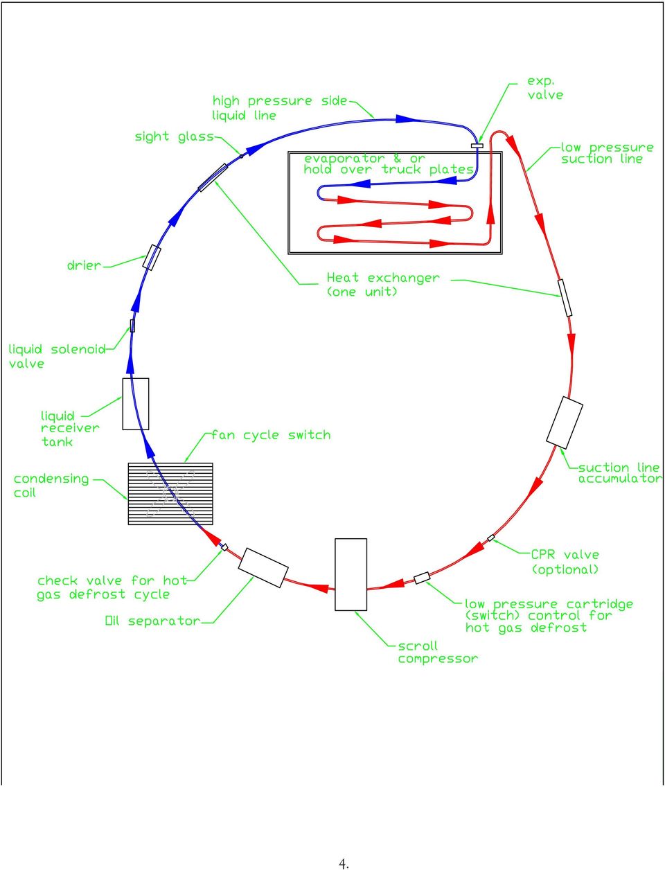
3 What Is The Refrigeration Cycle? Basic Cycle Operation 1. High pressure liquid refrigerant is fed from the condenser through the liquid line and the filter-drier to the metering device. 2. The high pressure side is separated from the low-pressure side using a thermostatic expansion valve (TEV). 3. The TEV controls the quantity of liquid refrigerant entering the evaporator. It causes the pressure of the refrigerant to the low side to be reduced. In reducing the low side pressure, the refrigerant reaches its boiling point and begins to vaporize. 4. The low pressure, low temperature refrigerant passes through the evaporator coil and heat flows through the walls of the tubing into the refrigerant to continue the boiling action until the refrigerant is completely vaporized. 5. The refrigerant is superheated to ensure there is no liquid fed through the compressor. As the refrigerant vapor flows through the compressor it is converted from a low pressure vapor to a hot, high pressure vapor and is forced out the compressor s discharge valve. 6. After leaving the compressor, the hot high pressure vapor enters the condensing coils and is air-cooled. The vapor returns to liquid state and the process repeats. 3.

4 4.
5 5.
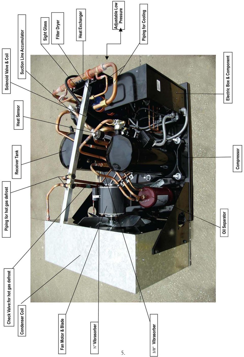
6 Refrigeration Components Compressor Oil Separator Check Valve For Hot Gas Defrost Air Cooled Condensing Coil Fan Cycle Switch High Pressure Control Switch Liquid Receiver Tank Liquid Solenoid Valve Drier Heat Exchanger Sight Glass Thermostatic Expansion Valve Evaporator (Plates) CPR Valve Suction Line Accumulator Cartridge Low Pressure (Switch) Control For Hot Gas Defrost Hot Gas By-Pass Valve (Low Temp) Adjustable Low Pressure Control Page 7-8 Page 9 Page 10 Page 11 Page 12 Page 13 Page 14 Page 15 Page 16 Page 17 Page 18 Page 19 Page 20 Page 21 Page 22 Page 23 Page 24 Page 25 Other Components and Illustrations Reverse Phase Relay & Timer Start & Run Capacitors Basic System Operation, Special Conditions & Maintenance Plates Manual Defrost Hot Gas Auto Defrost Blower System Impact of Ice & Frost Build-up Driver Tutorial Trouble Shooting Guide Page 26 Page 27 Page Page 30 Page Page 34 Page 35 Page

7 Compressor The compressor has two functions in the refrigeration cycle. It removes refrigerant vapor from the evaporator and reduces the pressure in the evaporator to a point where the required temperature can be maintained. Also, the compressor raises the pressure of the refrigerant vapor to a high enough level that it can be changed into liquid as it flows through the condenser. Scroll Compressor Protection 1. Temperature Operated Disk (TOD) A bi-metallic disk that senses compressor discharge temperature and opens at 270 degrees F Internal Pressure Relief (IPR): Opens at approximately 400+/-50 psi differential between high and low side pressures Floating Seal: Separates the high side from the low side. Also prevents the compressor from drawing into a deep vacuum and damaging (shorting) the Fusite electrical terminal. 4. Internal Motor Protection: An inherent protector sensing both internal temperatures and amperages. 7.
 A bi-metallic disk that senses compressor discharge temperature and opens at 270 degrees F. 1 2 3 2.")
8 Compressor - Key Components 1. Discharge Plenum 2. Upper Shell 3. Fixed Scroll 4. Orbiting Scroll 5. Crankcase 6. Stator Winding Eccentric Shaft 8. Lower Bearing Ring 6 9. Lower Bearing 10. Thrust Washer Magnet 12. Oil Tube 13. Shell Rotor 15. Stator Counterweight 17. Electric Terminal Terminal Cover 19. Suction Baffle 20. Slider Block 21. Separator Plate Discharge Tube 23. Check Valve 8.

9 Oil Separators An oil separator is a separation chamber for oil and discharge gas. It is installed on the discharge line between the compressor and the condenser. By using baffles and reducing the gas velocity, the oil is separated from refrigerant and returned to the crankcase of the compressor by means of a float valve and connecting tube. 9.

10 Hot Gas Defrost Check Valve (Sporlan ORD-4-20 Head Pressure Control Valve) ORD - The ORD valve is a pressure differential valve that responds to changes in the pressure difference across the valve. The valve designation stands for (Opens on Rise of Differential pressure.) Therefore, the ORD is dependent on some other control valve or action for its operation. (When defrost system is initiated, liquid line solenoid valves on plate, one is energized, the other valve de-energized, check valve responds to changes in pressure differential.) This will allow the hot gas out of compressor to bypass the condenser and circulate though the piping of one selected plate, melting any frost accumulation. Returning hot gas will now circulate through the condenser and back to the other plates for cooling. 10.
 This will allow the hot gas out of compressor to bypass the condenser and circulate though the piping of one selected plate, melting any frost accumulation.")
11 Air Cooled Condenser The condenser reverses the evaporator process. It changes high temperature, high pressure refrigerant vapor into refrigerant liquid. To drop the temperature of the vapor, an external device must be used to extract heat. Some systems are water-cooled and others are air-cooled. A watercooled system can be more desirable if low cost condensing water is available. To cool the refrigerant cold water is fed through the condensing coils to absorb heat. The condensed refrigerant liquid exits the system by way of a refrigerant liquid line. In this application an air-cooled system is used. It is easier to install, inexpensive and require no water. Furthermore, there is no risk of water freezing in colder, ambient temperatures. To cool the refrigerant, a fan blows over the condensing coils. The air absorbs the heat and becomes warmer, but the refrigerant successively becomes cooler in each row as it rejects more heat and returns to liquid state. Normally the condenser fan, if located so that it discharges on the compressor, will provide satisfactory cooling. For proper cooling, the fan must discharge air directly against the compressor. 11.

12 Fan Cycle Switch Condensing Temperature Control Condensing temperature must be controlled to maintain condensing pressure to guarantee proper system operation. The condensing temperature must be controlled so that liquid subcooling and liquid line flash gas can be maintained, adequate pressure at the inlet side of the thermo valve to obtain sufficient pressure drop across the valve port is provided, and systems with hot gas defrost can operate properly. Condensing temperature is controlled by fan-cycling and head-pressure regulator valves. To maintain air-cooled pressures in lower ambient conditions, a condenser fan pressure control may be used. The control acts to break the circuit to the condenser fan on a drop in condensing pressure and high pressure control, this is often described as a reverse-acting high pressure control. Fan cycle switch in this case is hard piped with the following non-adjustable settings: Cut-out Cut-in or - 10 psig or - 10 psig Fan Cycling Control Part # (Note: there is a difference between the High Pressure Control and the Fan Cycle Switch. The two differences are the spade orientation and the P/N) 12.

13 High Pressure Control Switch High Pressure Cutout Part # The high pressure safety switch is installed (in Condenser box) inside electric box next to the fan cycle switch as a precaution to shut off compressor motor when discharge pressure reaches 440 PSI to avoid damage to compressor. (Note: there is a difference between the High Pressure Control and the Fan Cycle Switch. The two differences are the spade orientation and the P/N) 13.

14 Liquid Receiver Tank A receiver is primarily a liquid storage tank for refrigerant which is not in circulation. All air cooled units equipped with expansion valves require a separate receiver to allow for the wide swings in ambient temperatures. In order to provide space to store the refrigerant charge when maintenance is required on the system, the receiver should be large enough to hold the entire refrigerant charge. A valve at the receiver outlet is required in order to pump the refrigerant charge into the receiver, an operation commonly called pumping the system down. 14.

15 Liquid Solenoid Valve A solenoid valve is an electrically controlled refrigerant flow control valve. It does not modulate; it is either open or closed. A solenoid valve is made up of a body, a plunger with an iron core that seats the valve orifice and an electrical solenoid coil. There are two types, normally open and normally closed. In this application, it is normally closed. The solenoid valve is closed when the coil is de-energized and the plunger is seated. Solenoid valves are used to trap the liquid refrigerant in the receiver tank and also for pump down purposes when servicing system. Direct acting Solenoid Valve operation, the plunger is mechanically connected to the needle valve. When the coil is energized, the plunger pulling the needle off the orifice is raised into the center of the coil. Solenoid valves are also used on Hot Gas Auto Defrost Systems, two on each plate, one normally open and the other normally closed. Normally closed valve must be energized or magnetized to open during system evacuation or pump down. 15.

16 Filter-Drier Filter-driers are used to protect the compressor from contamination, particularly moisture, left in the system at the time of installation and keeps the system free of impurities during operation, such as motor burn byproducts. 16.

17 Heat Exchangers Heat Exchangers are specifically designed for application on refrigeration systems to transfer heat Between liquid refrigerant leaving the condenser on the high pressure side of the system and refrigerant vapor leaving the evaporator on the low pressure side of the system. Heat transfer may be desirable for several reasons: To raise the vapor temperature to prevent frosting or condensation on the suction line. To evaporate any remaining liquid in the vapor stream to prevent possible compressor damage. To subcool the liquid to prevent flash gas in the liquid line. To increase system refrigerating capacity. Refrigerant vapor flows through the inner tube in a counterflow direction to the liquid refrigerant flowing in the annuls between the inner and outer tube. This counterflow path provides the greatest temperature difference between the two refrigerant streams to yield optimum heat transfer. To further maximize heat exchanger performance with minimum size, the inner tube is convulted to impart turbulence to both refrigerant flows while the straight through design helps maintain low refrigerant pressure drops. 17.

18 Sight Glass & Hermetic Moisture Indicators The HMI was designed to provide an accurate method of determining the moisture content of a system s refrigerant. Unique 3% high accuracy moisture indicator. Refrigerant level indicator. IF IT S NOT BLUE, IT S NOT DRY! (NOT NECESSARILY TRUE) 18.

19 Thermostatic Expansion Valves THERMOSTATIC EXPANSION VALVES: The most commonly used device for controlling the flow of refrigerant is the thermostatic expansion valve. Temperature of the vapor leaving the evaporator controls the flow leaving the expansion valve. The flow is controlled by a needle and diaphragm in the valve. The diaphragm is subject to three forces: evaporator pressure, the superheat spring and pressure exerted by the charge in the thermal bulb. As the refrigerant is in the evaporator, it is evaporating at its saturation temperature and pressure. As long as the thermal bulb is exposed to a higher temperature than the refrigerant in the evaporator the valve remains open. The superheat spring valve is fixed to close whenever the net difference between the bulb pressure and the evaporator pressure is less than the superheat setting. As the temperature of the refrigerant gas leaving the evaporator rises (an increase in superheat) the pressure exerted by the bulb increases and, in turn, the flow increases through the expansion valve. Alternately, when the superheat decreases (evaporator temperature of gas leaving is decreased) the thermal bulb pressure decreases as well and the flow through the expansion valve is reduced. Inlet Evaporator Pressure Superheat Spring Outlet Thermal Bulb (missing) Cross-Section of Thermostatic Expansion Valve Setting SUPERHEAT for Expansion Valves: Having the proper setting for the expansion valve is very important for the operation of the plates. In order to give the maximum performance without refrigerant flooding back on the compressor, the superheat of the system must be set. To set the SUPERHEAT for a one or multiple plate circuit, on a medium or low temperature truck body. 1. Measure the temperature at the outlet of the expansion valve 1/2 line. 2. Measure the temperature at bulb on suction line. 3. Adjust each expansion valve at the low end or bottom space of pull down to where there is only 5 degrees F to 10 degrees F temperature difference between the outlet of the expansion valve and at the expansion valve bulb. (At low end or bottom of pull down) when plates are near freezing. Example: valve 5 degrees F, bulb 10 degrees F. Temperature difference is 5 degrees F; this would be a good setting. Note: In this application and for better performance Hercules uses Sporlan Balanced Port TEV 19.

20 Evaporator (Plates) The evaporator is the main part of the low pressure side of the refrigeration system. In the evaporator, liquid refrigerant boils and evaporates. As the liquid refrigerant changes to vapor, the heat is absorbed in the evaporator and freezes the eutectic solution to desired temperature. 20.

21 Suction Line Accumulator A suction accumulator is used to prevent liquid flood-back. It intercepts liquid refrigerant before it can reach the compressor crank case. It is located in the compressor suction line between the compressor and the evaporator. Prevents Compressor Damage Due to Sudden Return of Liquid Refrigerant Through the Suction Line When a system sends a slug of oil and refrigerant to the accumulator, oil must be returned to the crankcase at a fast enough rate to prevent bearing damage. At the same time liquid refrigerant must be metered back slowly enough to prevent valve or other compressor damage. 21.
22 CPR Valve The Crankcase Pressure Regulator Valve (CPR Valve) regulates suction pressure at the compressor to prevent overloading on the compressor motor. The valve setting is determined by a pressure spring and the valve modulates from fully open to fully closed in response to the outlet pressure. Located between the evaporator and the condenser, the CPR valve is normally used to prevent motor overloading during pull-down cycle. Service: Since the CPR valve is hermetic, it cannot be disassembled for inspection and cleaning, and usually must be replaced if it becomes inoperative. Failure of a CPR valve to operate can be caused by foreign material inside the valve. It is possible this material can be dislodged by opening the adjustment screw all the way with the system running. If this does not correct the malfunction, the valve should be removed and replaced with a new CPR. (For better performance the CPR valve is not recommended for use in conjunction with hot gas defrost and not necessary for a scroll compressor. ) 22.
23 Cartridge Low Pressure (Switch) Control for Hot Gas Defrost - Opens on Pressure Fall The Safety Low Pressure Switch ( psi) is activated during Hot Gas operation to allow the minimum suction pressure within the performance window of the compressor. Upon start up of Defrost, operational adjustable Low Pressure Switch (set at 25 to 30 psi) will be disabled while this safety switch will be activated to allow compressor to operate (A) During low ambient conditions (B) Plates not completely depleted (C) Used only on medium temperature system SLP /- 5 PSI 23.
24 Hot Gas Discharge By-Pass Valve (DBV) (Low Temp) DBV is used on low -plates blower equipped with Hot Gas Defrost Check Valve (head pressure control valve) to adapt compressor capacity to actual evaporator load by supplying a replacement capacity in the form of Hot Gas. The pressure setting of the DVB (10-11#) must be lower than the check valve setting (20#) for each valve to function properly. DBV with external equalizer is installed in a bypass line between the high and low pressure sides of the refrigeration system and is designed for direct Hot Gas injection into the suction line. DBV responds to changes in down-stream of suction pressure. When the evaporating pressure is above the valve setting, the valve remains closed. As the suction pressure drops below the valve setting, the valve responds and begins to open. As with all modulating type valves, the amount of opening is proportional to the change in the variable being controlled - in this case the suction pressure. As the suction pressure continues to drop, the valve continues to open until the limit of the valve stroke is reached. 24.
25 Low Pressure Control The low pressure control is used to protect the motor. It operates by cutting a circuit when the evaporating pressure becomes too low, causing the assembly to contract and the contacts to open. When this happens, the motor in the compressor shuts off. There are also dual controls available with one switch that cuts out on either high or low pressure. 25.
26 Reverse Phase Relay (& Timer) (Used on 3 Phase Motors Only) Located in the Condenser Box inside electrical box. This Phase sensitive control provides an isolated contact closure to protect 3 phase compressor motor from incorrect rotation. 26.
27 Start & Run Capacitor Normally used on single phase motors where system design requires high starting torque & to improve run efficiency. Located in condenser box & inside electrical box & possibly on motor housing. Capacitor must be discharged before testing with OHM meter with capacitor testing capabilities. No resistance indicates faulty or damaged capacitor. The PTC Start Assistance The PTC (Positive Temperature Coefficient) resistor is used for applications where high starting torque is not required. The PTC resistor is connected in parallel with the run capacitor, placing it in series with the start winding. The PTC has a low resistance when it is cold. When the motor starts, the low resistance causes a large current to flow through the resistor. The current drawn by the resistor is out of phase with the current drawn by the motor windings, and this provides the torque to start. As soon as the resistor draws current, it begins to heat, and the positive temperature effect of the resistor causes it to rapidly increase its resistance. By the time the motor reaches full speed, very little current is drawn. Run Capacitors Run capacitors are used on compressors to improve efficiency, raise the motor s power factor, and lower noise. Run capacitors are continuously in the operating circuit and are normally of the metallized film type. They are manufactured in oval or round cans. Start Capacitor Run Capacitor 27.
28 Basic Systems Operations Special Conditions & Maintenance Eutectic cold plate passive refrigeration systems are designed to provide consistent uniform temperature throughout the load space during the delivery day. This is accomplished by freezing eutectic plates with an electrically controlled and operated condenser unit during off delivery time. Components consist of holdover plate assemblies mounted across the front wall, ceiling and side walls to minimize load space taken up by the unit. Adequate plug-in time (10-12 hours) is essential to insure that all plates are totally frozen to allow maximum holdover times for route delivery. **NOTE**: Plates are designed with a specific eutectic temperature in cooling. Extreme freeze is called subcooled. A plate is only designed to go 10 degrees F below the plate specifications. COLD AMBIENT CONDITIONS: Medium temperature systems that operate in colder than desired body operating temperatures may experience lower body/product temperatures. Some occasions could result in frozen product. The conditions that may lead to product temperature problems usually occur when plate systems are operated on electric power and product is loaded at or near proper temperature and body is exposed to low ambient temperatures for longer than overnight. Normally this would be a weekend or a period of several days. A partially loaded body may contribute to the problem, as product will freeze faster due to a smaller product mass. The ONLY positive method to prevent product freezing is to load trucks just prior to beginning of the delivery day or to add an auxiliary heating system. However, again, product freezing MAY occur if ambient temperatures remain below critical product temperatures and allow body temperature to drop below critical temperature during multiple door openings. Auxiliary electric heaters are available for product freeze prevention/reduction and may be wired directly to the refrigeration power receptacle. The heater thermostat should be set slightly above product freezing temperature. RECOMMENDED OPERATING PROCEDURES: The following operation procedure guidelines are essential to maximize refrigeration system performance and extend component life: 1. Always insure that unit master control switches are OFF before connecting or disconnecting 220vac AC electrical power. 2. Insure that all plates are relatively free of frost and ice buildup (see defrosting procedure). 3. Insure that all product loaded is at proper temperature. 28.
29 Basic Systems Operations Special Conditions & Maintenance 4. Insure that product stacking allows for proper air circulation. 5. Check all door seals for leaks. 6. Open doors only as necessary to load or remove product and minimize door open times. 7. Fans on blower units are activated with door switches and should stop when any door is opened and run when all doors are closed and thermostat is satisfied. 8. Dust and dirt accumulations on condenser coils should be removed when buildup occurs or every 30 days during hot weather. This will dramatically enhance pull-down times and extend compressor life. The following suggestions may reduce product freeze damage in many instances: 1. When extended periods of colder ambient temperature exist, plug system into electrical power, but do not turn on condenser unit. This will allow fans to operate only on blower systems and circulate air in body. 2. Set fan thermostat on blower systems close to desired body temperatures to allow air circulation for longer periods. However, be aware that fans will shut down as body temperature drops below thermostat setting. 29.
30 Plates Manual Defrost WHY DEFROST PLATES: The purpose of any defrosting procedure is to maximize the ability of the holdover plate to absorb heat and thus improve the system to maintain body temperatures. SOME FACTORS that affect frost formation and the need to defrost are: 1) Climate conditions. 2) Temperatures of holdover plates. 3) Operational conditions relating to door open frequency and open time duration. 4) Equipment conditions caused by poor gaskets allowing air to leak into the body. 5) Moisture buildup on Product. A GENERAL RULE OF THUMB. Any accumulation of ice on plates will severely affect cooling capacity. Be AWARE when the accumulation becomes about ¼ to 3/8 thick or more and be ALARMED when accumulation becomes ½ thick. Ice buildup of ¾ or more can cause severe damage to product and plates. Plates frosted to the ceiling, wall or each other have lost a minimum of half their ability to absorb heat. Major structural damage will occur over several days, as ice accumulation can jack the plates off the wall or ceiling. This accumulation may occur in several days. HOW TO DEFROST PLATES Preferred Defrost Method: Use of HOT water (up to 140 degrees F) is the most efficient method of defrosting, as it is very quick and will minimize the thawing of the holdover plate. This requires less time for holdover plate refreeze and body temperature recovery. Water spray header lines are incorporated into the Dole blower system to help simplify defrosting. Water enters through a hose connection near the roadside condenser section and is piped to these header lines above the plates. It is then distributed evenly over the plate surfaces. After defrost water cascades over the plates, slush is eliminated from the system through drain holes in the front pan of the body. Collapsible neoprene tubing (Kazoos) prevents air infiltration when these holes are in use as drains. First Alternate Method: Use of readily available COLD water will also defrost the holdover plates, however, much longer time is required and additional holdover plate thawing will occur. Second Alternate Method: Leave the body doors open and allow ambient air to circulate over the plates. However, this method takes considerably more time and additional plate refreeze and body temperature recovery time. 30
31 Hot Gas Auto Defrost and Blower System (with Dole Controller) Overview. This Econo-Cel Blower Unit has three cold plates, three propeller fans, and electric controls for 12 volt DC & 220 VAC for fan operation. The Unit is rated 112,030 BTU holdover capacity with +18 degrees F eutectic. When matched with an air-cooled condensing unit it can provide cooling all day for a refrigerated delivery truck. The condensing unit is plugged into 220 VAC supply overnight to freeze the eutectic plates for the next day s service. Until now this unit was defrosted once or twice a week using a water hose connection to shower the plate surface with water. Now, a hot-gas defrost feature has been added to make defrost completely automatic. Each plate will be defrosted once every 3 days using computerized controls. Details. This system utilizes the heat from the refrigeration that usually goes out the air cooled condenser to defrost the cold plate. The same tubing in the cold plate that freezes the solution is used to thaw the frost and ice on the plate. There are 12 volt DC solenoid valves in the Econo-Cel package that control the flow of refrigerant for freezing or defrosting. While one plate is being defrosted the other plates are being frozen. Normal defrost time is 120 minutes, and during this time ALL the cooling performance is focused on 2 plates while 1 plate is being defrosted. The condensing unit will have an additional gas pressure regulated check valve. 31.
32 Hot Gas Auto Defrost and Blower System (continued) Hot gas defrost operation is controlled by a computerized unit that will control the defrost schedule for Cold Plates. The controller is programmed by the factory, thus there is no setting required from the user and/or service personnel. Controller is wired to: 12vdc from the vehicle battery A dry contact relay in the condensing unit, to initiate defrost upon plug in and to activate hot gas defrost 12 volt solenoids. OPERATION: Length of defrosting: The controller will sense when the truck is plugged in from the dry contact closure. The first time used it will defrost for two hours and then switch the defrost off. It will defrost for two hours and then switch the defrost off. If during the two hours, the truck is unplugged (or if there is a power failure), it will keep track of the available time and try to defrost for a total cumulative period of 2 hours within the first four hours after it is first plugged in. After the four actual hours expire there will be no more defrost allowed until the next day. NOTE: While a plate is defrosting, all other plates are being refrigerated. Example 1: The truck is plugged in at 6pm. From 6 until 10pm 2 hours will be spent in defrost. If there is no power failure or unplugging, then defrost is done at 8pm. Example 2: The truck is plugged in at 6pm. There is a power failure from 7 to 8pm. Defrost is done at 9pm. Example 3: The truck is plugged in at 6pm. The truck is unplugged at 6:30pm for tire changing. The truck is plugged back in at 9pm the same night. There is only ½ hour of defrost this evening. Example 4: The truck is plugged in at 6pm and unplugged at 10pm for servicing. The truck is plugged back in at 1am the following morning. There are 2 hours defrost from 6 to 8 pm. The event from 10pm to 1am is ignored. There is no more defrost until after the next work shift. 32.
33 Hot Gas Auto Defrost and Blower System (continued) Sequential operation: After a defrost period is completed and the truck is left unplugged for a work shift, the next defrost bank (or plate) will be selected and defrosted. The controller senses the time the truck is unplugged in order to learn when the next defrost is needed and thus learns to ignore most power failures. If the 12vdc is removed (i.e. truck battery is removed) from the controller and then reapplied, the controller goes back to start and may start to defrost the first bank (plate). The controller is factory programmed and will keep the program for years in the internal EEPROM. The controller works without knowing the actual time of day or day of the week; there is no programming required from the user. The controller learns from the driver s habits. Trucks with 24 volt starting: controller must be connected to the battery that has the negative connected to the chassis. Special programming can be provided by the factory (Dole Refrigerating Co.). Other functional details: There is no on/off switch There is an automatic reset circuit breaker to protect the solenoid wiring in case of short circuits. There is no installer or operator programming or settings required. There is no opportunity for someone to interrupt proper defrosting. 33.
34 Impact of Ice & Frost Build UP Accumulation of frost and ice on plates will severely effect cooling capacity. (SEE CHART BELOW). Be AWARE when the accumulation becomes about ¼ to 3/8 thick or more and be ALARMED when the accumulation becomes ½ thick. Ice buildup of ¾ or more can cause severe damage to product and plates. Plates frosted to the ceiling, wall or each other will lose 30% or more of their ability to absorb heat. In addition, major structure damage may occur as the ice can jack the plates off the wall or ceiling. This accumulation may occur in several days. DOLE RERIGERATING COMPANY, Lewisburg, TN, Engineering Department IMPACT OF ICE BUILDUP ON PLATES EFFICIENCY Snow Ice and Hard Ice 34
35 35.
36 Compressor Won t Run Trouble Shooting I. Check power source and make sure power is on all legs. II. Check coil on contactor. III. Check contacts. IV. Check high/low pressure switch in pressure controller. V. Check bump start time delay relay. VI. Check discharge line heat switch. VII. Unit out of refrigerant. Check gauges. Lack of pressure indicates system is out of refrigerant. Find leak and repair, evacuate and charge. VIII. Check CPR valve adjustment (if supplied). IX. Check phase reversing relay. Replace if necessary. X. Check liquid line solenoid valve coil. XI. Check fan cycle switch if supplied. XII. Check start and run capacitor (single phase only). Q. Compressor and condenser fan are cycling? A. Check pressure with gauges and check sight glass. Low pressure and bubbles in sight glass will be an indication of refrigerant leak. Repair leak, evacuate, system and charge (replace filter/drier if needed). Q. What is a normal head pressure on medium and low temperature system? A. Head pressure varies depending on ambient temperature. The hotter the ambient temperature, equate to higher head pressure. (head pressure will vary between 270# to 325#). Head pressure will decline as temperature of plates become colder. When plates are frozen head pressure could be as low as 225#. Head pressure on a system with hot gas defrost is 170#, while low pressure (suction side) could be as low as 15# depending on settings of pressure controller. (Medium temperature low pressure setting should not go below 15#). Normal suction pressure on a low temperature unit could go as low as 5#. 36
37 Trouble Shooting (continued) Plate Suspected of Not Performing Properly 1.Check solution eutectic having leaked out of the holdover plate. This will show up on the plate s exterior surface as well as on the floor or the adjacent wall. 2. Refrigerant Leak in the tubing inside the plate; the outer surface will exhibit a large bulge in the plate sides. Contact Dole Refrigeration for replacement and/or repair. Remove and replace upon arrival of the repaired plate. 3. Malfunctioning of the expansion valve. A malfunctioning expansion valve is usually caused by moisture collecting in the form of ice on the valve seat, or bulb not properly secured to the suction line with cork tape or an improperly adjusted valve can give similar results. 4. Pump down system, clean expansion valve filter, evacuate and charge. BLOWER UNIT FAN continues to run when door is open. 1. Check door switch re-alignment and/or replace if switch is damaged. 2. Check thermostat for proper operation. 3. Check for short in circuit. BLOWER THERMOSTAT SETTING Keep the thermostat adjusted to attain desired temperature in body. The function of the thermostat is to start and stop the blower fans only. It has NO CONTROL over the operation of the condensing unit. FAN MOTORS Blower fan motors are brushless. No maintenance required. 37.
38 38.
Why and How we Use Capacity Control
 Why and How we Use Capacity Control On refrigeration and air conditioning applications where the load may vary over a wide range, due to lighting, occupancy, product loading, ambient weather variations,
Refrigeration Basics 101. By: Eric Nelson
 Refrigeration Basics 101 By: Eric Nelson Basics Refrigeration is the removal of heat from a material or space, so that it s temperature is lower than that of it s surroundings. When refrigerant absorbs
Table Z. Troubleshooting Chart for Air Conditioners. Cause
 Troubleshooting Chart for Air Conditioners Type of Unit Complaint Cause With open-type compressor Electric motor will not start Power failure Check circuit for power source Compressor stuck Locate cause
How To Defrost A Truck
 DOLE REFRIGERATING COMPANY 1420 Higgs Road Lewisburg, Tennessee 37091 Phone (931) 359-6211 1-800-251-8990 www.doleref.com SEQUENTIAL DEFROST SERVICE MANUAL June 2002 1 SEQUENTIAL DEFROST Table of Contents
Table V. Troubleshooting Checklist for Refrigeration Systems. Air or non-condensable gas in system. Inlet water warm.
 Table V Troubleshooting Checklist for Refrigeration Systems TROUBLE POSSIBLE CAUSE CORRECTIVE MEASURE High condensing pressure. Low condensing pressure. Air or non-condensable gas in system. Inlet water
How To Understand Evaporator
 SECTION 5 COMMERCIAL REFRIGERATION UNIT 21 EVAPORATORS AND THE REFRIGERATION SYSTEM UNIT OBJECTIVES After studying this unit, the reader should be able to Define high-, medium-, and low-temperature refrigeration.
Heating, Ventilation, Air Conditioning and Refrigeration (HVACR)
") Heating, Ventilation, Air Conditioning and Refrigeration (HVACR) I. Demonstrate safety skills in typical HVACR work situations to NATE Core Installer Knowledge Areas for Technician Excellence for Safety
Heating, Ventilation, Air Conditioning and Refrigeration (HVACR) I. Demonstrate safety skills in typical HVACR work situations to NATE Core Installer Knowledge Areas for Technician Excellence for Safety
SECTION 5 COMMERCIAL REFRIGERATION UNIT 22 CONDENSERS
 SECTION 5 COMMERCIAL REFRIGERATION UNIT 22 CONDENSERS UNIT OBJECTIVES After studying this unit, the reader should be able to explain the purpose of the condenser in a refrigeration system. describe differences
543-0032-00, 943-0032-00. User s Manual
 543-0032-00, 943-0032-00 User s Manual 1 Comfort Alert Diagnostics Faster Service And Improved Accuracy The Comfort Alert diagnostics module is a breakthrough innovation for troubleshooting heat pump and
Any Service Technician Can Fix It A Good Service Technician Can Figure Out What s Wrong With It.
 I Dave s Statement If the thermostat calls for cooling, and the furnace fan is running properly, and the coil airflow is adequate, and the condenser fan is running properly, and the condenser airflow is
DESIGN STANDARDS SECTION 23 60 00
 PART 1 - GENERAL 1.01 Work included: A. Piping, tubing and fittings. B. Piping specialties. C. Special duty valves. D. Refrigerants. E. Chillers. F. Refrigerant monitors. 1.02 General requirements: A.
Service manual. Website: www.andico.com.au CAUTION - BEFORE SERVICING THE UNIT, READ THE SAFETY - PRECAUTIONS IN THIS MANUAL.
 Website: www.andico.com.au Service manual CAUTION - BEFORE SERVICING THE UNIT, READ THE SAFETY - PRECAUTIONS IN THIS MANUAL. - ONLY FOR AUTHORISED SERVICE PERSONNEL. MODELS: MPK1-09CR-QB8 MPK1-12ER-QB6
Refrigerant Changeover Guidelines R-22 to R-407C. Leading the Industry with Environmentally Responsible Refrigerant Solutions
 Refrigerant Changeover Guidelines R-22 to R-407C Leading the Industry with Environmentally Responsible Refrigerant Solutions Copeland does not CFC advocate the wholesale changeover of HCFC HCFC refrigerants
HEAT PUMP FREQUENTLY ASKED QUESTIONS HEAT PUMP OUTDOOR UNIT ICED-UP DURING COLD WEATHER:
 HEAT PUMP FREQUENTLY ASKED QUESTIONS HEAT PUMP OUTDOOR UNIT ICED-UP DURING COLD WEATHER: It is normal for a heat pump to have a build up of white frost on the outside coil during cold damp weather. The
DEFROSTING. Service Engineers Section Technical Bulletin No 3
 Service Engineers Section Technical Bulletin No 3 DEFROSTING 1. INTRODUCTION This bulletin is presented to cover the methods used and problems experienced with defrosting of coils for chill and frozen
SYLLABUS For BASIC TRADE COURSE (360 Hours) On REFRIGERATION AND AIR CONDITIONING
 On REFRIGERATION AND AIR CONDITIONING") SYLLABUS For BASIC TRADE COURSE (360 Hours) On REFRIGERATION AND AIR CONDITIONING INDEX 1. Introduction 3 2. Objectives 3 3. Employment Opportunity 4 4. Course Structure 4 5. Entry Qualification 4 6. List
SYLLABUS For BASIC TRADE COURSE (360 Hours) On REFRIGERATION AND AIR CONDITIONING INDEX 1. Introduction 3 2. Objectives 3 3. Employment Opportunity 4 4. Course Structure 4 5. Entry Qualification 4 6. List
POLICY BULLETIN Tecumseh Compressor Company Compressor Group
 to Bulk Milk Coolers and Other System Page 1 of 5 Overall reliability can be enhanced if there exists a complete understanding of the features, system design, installation requirements, processing, charging
It will be available soon as an 8.5 X 11 paperback. For easier navigation through the e book, use the table of contents.
 The System Evaluation Manual and Chiller Evaluation Manual have been revised and combined into this new book; the Air Conditioning and Refrigeration System Evaluation Guide. It will be available soon as
Refrigerant Changeover Guidelines R-22 to R-407C. Leading the Industry with Environmentally Responsible Refrigerant Solutions
 Refrigerant Changeover Guidelines R-22 to R-407C Leading the Industry with Environmentally Responsible Refrigerant Solutions Emerson Climate CFC Technologies, Inc. does not advocate the HCFC wholesale
Troubleshooting HVAC/R systems using refrigerant superheat and subcooling
 Troubleshooting HVAC/R systems using refrigerant superheat and subcooling Application Note Troubleshooting and servicing refrigeration and air conditioning systems can be a challenging process for both
COMPRESSOR REPLACEMENT PROCEDURE
 COMPRESSOR REPLACEMENT PROCEDURE Bard Manufacturing Company Bryan, Ohio 43506 Since 1914...Moving ahead just as planned Manual No.: 2100-003E Supersedes 2100-003D File: Volume I, Tab 1 Date: 06-25-02 Copyright
INSTALLATION INSTRUCTIONS HOT GAS BYPASS SYSTEM DESIGN MANUAL
 INSTALLATION INSTRUCTIONS HOT GAS BYPASS SYSTEM DESIGN MANUAL MODELS: WA/WL44H WA/WLH WA/WL70*H NOTE: Electrical data presented in this manual supersedes any other data f the above listed models. Bard
National Competency Based Skill Training Refrigeration and Air-conditioning Mechanic Logbook
 National Competency Based Skill Training Refrigeration and Air-conditioning Mechanic Logbook Trainee:... Training Provider:... Year:... Trainee Contact no:... Competency Based Skill Training Logbook Introduction
Automobile Air Conditioning Primer
 Automobile Air Conditioning Primer An air conditioner is basically a refrigerator without the insulated box. It uses the evaporation of a refrigerant, like Freon, to provide cooling. The mechanics of the
Solenoid Valves and Their Importance in Refrigeration Systems. October 2007
 Solenoid Valves and Their Importance in Refrigeration Systems October 2007 Overview Introduction Solenoid valves play an important role within refrigeration and air conditioning systems, controlling the
SECTION 15750 PACKAGED ROOFTOP AIR CONDITIONING UNITS
 SECTION 15750 PART 1 - GENERAL 1.01 DESCRIPTION A. Section includes requirements for roof mounted, self-contained units, with electric cooling, and electric or reverse refrigeration cycle (heat pump) heating
PC1130 Electric Air Compressor
 Senco Products Inc. 8485 Broadwell Road Cincinnati, Ohio 45244 PC1130 Electric Air Compressor Operating Instructions 2006 by Senco Products, Inc. Warnings for the safe use of this tool are included in
Heat Pump Water Heater IOM Manual
 Heat Pump Water Heater IOM Manual Installation Operation & Maintenance This manual is intended as an aid to qualified service personnel for proper installation, operation and maintenance of the heat pump
MP-4000 Alarm List (Software version 2.4.3 or later)
") Service Bulletin SUBJECT: MP4000 Alarm s BULLETIN: C 100 DATE: June 19, 2013 ALARM LIST Where it is possible the alarm number is kept the same as for MP-3000. MP-3000 holds alarm number from 0 to 127.
Service Bulletin SUBJECT: MP4000 Alarm s BULLETIN: C 100 DATE: June 19, 2013 ALARM LIST Where it is possible the alarm number is kept the same as for MP-3000. MP-3000 holds alarm number from 0 to 127.
Oil and Coolant Circulating Heating System. Model - OCSM
 Oil and Coolant Circulating Heating System Model - OCSM Installation & Operation Manual 216280-000 REV 2 Identifying Your System The HOTSTART heating system is designed to heat fluids for use in marine
CDS TROUBLESHOOTING SECTION I. VACUUM. 1.0. Weak vacuum at wand. Gauge reads normal (10hg to 14hg)
") CDS TROUBLESHOOTING SECTION I. VACUUM 1.0. Weak vacuum at wand. Gauge reads normal (10hg to 14hg) 1.1. Clogged hoses or wand tube. Disconnect hoses and carefully check for an obstruction. 1.2. Excessive
CDS TROUBLESHOOTING SECTION I. VACUUM 1.0. Weak vacuum at wand. Gauge reads normal (10hg to 14hg) 1.1. Clogged hoses or wand tube. Disconnect hoses and carefully check for an obstruction. 1.2. Excessive
ENGINE COOLING SYSTEM
 ENGINE COOLING SYSTEM 1988 Toyota Celica 1987-88 TOYOTA Engine Cooling Systems Celica DESCRIPTION The basic liquid cooling system consists of a radiator, water pump, thermostat, cooling fan, pressure cap,
ON-VEHICLE INSPECTION
 Sight Glass I11244 ONVEHICLE INSPECTION 1. INSPECT REFRIGERANT VOLUME Observe the sight glass on the liquid tube. AC3 AC22F05 Test conditions: Running engine at 1,500 rpm Blower speed control switch: HI
PRE-ASSEMBLED REMOTE REFRIGERATION SYSTEMS
 NOR-LAKE, INCORPORATED 727 Second Street P.O. Box 248 Hudson, Wisconsin 54016 800-955-5253 715-386-2323 866-961-5253 Parts 800-388-5253 Service 715-386-4291 FAX www.norlake.com Split-Pak Pre-Assembled
Air Conditioning Sign-Off Sheet
 Air Conditioning Sign-Off Sheet Printed Technician Name Address Social Security Number Telephone Number City State Zip Code Install Or Verify The Accuracy Of An Air Conditioner s Installation The candidate
Geothermal Alliance of Illinois. TXVs Theory and Fundamentals John Haug Senior Application Engineer Emerson Climate Technologies - Flow Controls
 Geothermal Alliance of Illinois TXVs Theory and Fundamentals John Haug Senior Application Engineer Emerson Climate Technologies - Flow Controls Thermal Expansion Valve Topics Anatomy Operation Terms &
Skills Canada National Competition Instructions and Competition Details 38 Refrigeration and Air Conditioning / Post - Secondary May 27-30, 2015 -
 Skills Canada National Competition Instructions and Competition Details / Post - Secondary May 27-30, 2015 - Saskatoon 1. Test Project Details This project is designed to test the range of skills used
System Trouble Shooting Fault Location REFRIGERATION AND AIR CONDITIONING. Fitters notes
 System Trouble Shooting Fault Location REFRIGERATION AND AIR CONDITIONING Fitters notes Contents Page Faults on refrigeration systems, general...3 Fault location without the use of instruments...3 Categorisation...3
ASHRAE Boston Chapter Meeting Designing AC Refrigeration Systems Lessons Learned February 11, 2014
 ASHRAE Boston Chapter Meeting Designing AC Refrigeration Systems Lessons Learned February 11, 2014 Explanation of the refrigeration cycle. Compressors. Benefits and operating characteristics. -Reciprocating
Characteristics of Evaporators
 Characteristics of Evaporators Roger D. Holder, CM, MSME 10-28-2003 Heat or Energy In this paper, we will discuss the characteristics of an evaporator coil. The variance of the operational condenses of
SECTION 23 81 03 - PACKAGED ROOFTOP AIR CONDITIONING UNITS NON-CUSTOM
 SECTION 23 81 03 - PACKAGED ROOFTOP AIR CONDITIONING UNITS NON-CUSTOM PART 1 - GENERAL 1.1 SUMMARY A. Section Includes: 1. Packaged rooftop air conditioning unit (5 tons and smaller). 2. Roof curb. 1.2
PROAIR Water-Cooled Air Conditioner. CR43WC Model INSTRUCTION MANUAL. Rev. E 2013 Pentair Technical Products P/N 10-1008-167
 PROAIR Water-Cooled Air Conditioner CR43WC Model INSTRUCTION MANUAL Rev. E 2013 Pentair Technical Products P/N 10-1008-167 87976466 TABLE OF CONTENTS HANDLING & TESTING THE AIR CONDITIONER...3 INSTALLATION
CONTAMINANT REMOVAL FROM CENTRIFUGAL SYSTEMS
 CONTAMINANT REMOVAL FROM CENTRIFUGAL SYSTEMS BULLETIN 240-10-3 June 2004 Supersedes June 1983 Many centrifugal systems get little maintenance. As a result they operate with the refrigerant highly contaminated
Dealer Sales & Service Guide
 Analog Models w/thermostat or Timerstat Heat Siphon Not Starting 1 BREAKER TRIPPED - Check Breaker Box for correct size breaker Breakers: EX; Domestic model 2.25hp (20amp) 3.25hp (40amp) 5hp (50amp) check
COMMERCIAL HVAC CHILLER EQUIPMENT. Air-Cooled Chillers
 COMMERCIAL HVAC CHILLER EQUIPMENT Air-Cooled Chillers Technical Development Programs (TDP) are modules of technical training on HVAC theory, system design, equipment selection and application topics. They
Flushing and Cleaning the A/C System
 Flushing and Cleaning the A/C System Once an AC system has been contaminated or has suffered a failure, the most important part of the AC service to restore the cooling performance to the system = FLUSHING
Refrigeration and Airconditioning Prof. M. Ramgopal Department of Mechanical Engineering Indian Institute of Technology, Kharagpur
 Refrigeration and Airconditioning Prof. M. Ramgopal Department of Mechanical Engineering Indian Institute of Technology, Kharagpur Lecture No. # 22 Refrigeration System Components: Compressor (Continued)
MACS Recommended Service Procedures
 MACS Recommended Service Procedures Initial Customer Contact It is important to obtain information from the customer identifying the problem and any previous servicing history prior to attempting repair
MAC-120HE-01 Air-Cooled Chiller
 MAC-120HE-01 Air-Cooled Chiller 10 Ton / 120,000 BTUH Air-Cooled Chiller 208/230-1-50/60 1 HVAC Guide Specifications Air-Cooled Liquid Chiller Nominal Size: 10 Tons Multiaqua Model Number: MAC-120HE-01
SWIMMING POOL HEAT PUMP
 SWIMMING POOL HEAT PUMP Installation & User Manual Model HP40B HP50B HP65B Hayward Pool Products Canada, Inc. T: 1-888-238-7665 www.haywardpool.ca CONTENT I. Application 4 II. Features 4 III. Technical
LOBOY 16 AIR CONDITIONERS
 INSTRUCTION MANUAL FOR: LOBOY 16 AIR CONDITIONERS McLean Midwest Corp. dba: McLean Cooling Technology 11611 Business Park Blvd. N Champlin, MN 55316 Tel: 763-323-8200 Fax: 763-576-3200 www.mcleancoolingtech.com
REFRIGERATED TYPE COMPRESSED AIR DRYERS INSTRUCTION MANUAL. For Sales & Service please contact:
 7610.478.16 8/99 INSTRUCTION MANUAL Models 8005, 8010, 8015 For Sales & Service please contact: CENTRAIR Air Systems & Supplies Phone: 705-722-5747 Fax: 705-722-5458 Email: sales@centrair.ca Website: www.centrair.ca
NO-FROST CUSTOMER SUPPORT INFORMATION INFORMATION ON THE NO-FROST TECHNOLOGY WHITE GOODS
 INFORMATION INFORMATION ON THE TECHNOLOGY The -Frost refrigerators are different from the other static refrigerators in terms of their operational system. In normal refrigerators, in the freezing section,the
01-3 6820-11 6820-11 AIR CONDITIONER GENERAL 1. SPECIFICATIONS AIR CONDITIONER REXTON 2010.01
 682011 013 GENERAL 1. SPECIFICATIONS 682011 014 682011 2. REPAIR INSTRUCTIONS 1) Precautions for Working with R134a R12 refrigerant and R134a refrigerant are not compatible. These refrigerants must never
CARING FOR YOUR WATER HEATER
 http://waterheatertimer.org/troubleshoot-rheem-tankless-water-heater.html Water Heater Inspections CARING FOR YOUR WATER HEATER Venting System (Direct Vent Only) The venting system should be inspected
MAXIMUM HEAT LOAD TEMPERATURE TESTING ( Differential Temperature Testing )
") MAXIMUM HEAT LOAD TEMPERATURE TESTING ( Differential Temperature Testing ) The Concept Maximum Heat Load Temperature Testing is a powerful air-conditioning diagnostic and evaluation technique. It is also
MAXIMUM HEAT LOAD TEMPERATURE TESTING ( Differential Temperature Testing ) The Concept Maximum Heat Load Temperature Testing is a powerful air-conditioning diagnostic and evaluation technique. It is also
Engineering Recommendation on: Accumulators Revised 6-17-99 Issued January 10, 1979 Page 1 of 7
 Issued January 10, 1979 Page 1 of 7 Accumulators have long been recognized by the industry as an effective means of maintaining good system balance by storing excess refrigerant as the condenser or evaporator
Training Syllabus to Instruct/Prepare for the ASE Transit Bus HVAC Test
 APTA STANDARDS DEVELOPMENT PROGRAM RECOMMENDED PRACTICE American Public Transportation Association 1666 K Street, NW, Washington, DC, 20006-1215 APTA BTS-BMT-RP-001-10 Approved October, 2010 APTA Bus Maintenance
Technical Training Associates Presents. Commercial Refrigeration Equipment Servicing Part 1
 Technical Training Associates Presents Commercial Refrigeration Equipment Servicing Part 1 By Jim Johnson A Practical Approach To The Fundamentals Of Walk-Ins, Reach-In and, Display Cases: Restaurant,
HVAC SYSTEM (HEATER, VENTILATOR, AND A/C)
") HVAC SYSTEM (HEATER, VENTILATOR, AND A/C) HEATER SYSTEM 1. Heater System A: GENERAL A semi-center type integrated air conditioning unit is used, where a high performance heater core and an evaporator core
HVAC SYSTEM (HEATER, VENTILATOR, AND A/C) HEATER SYSTEM 1. Heater System A: GENERAL A semi-center type integrated air conditioning unit is used, where a high performance heater core and an evaporator core
specializing in AIR CONDITIONING, PARTS AND SYSTEMS for your classic vehicle PERFECT FIT IN-DASH HEAT/ COOL/ DEFROST 1967-72 CHEVROLET PICKUP
 specializing in AIR CONDITIONING, PARTS AND SYSTEMS for your classic vehicle PERFECT FIT IN-DASH HEAT/ COOL/ DEFROST 1967-72 CHEVROLET PICKUP CONTROL & OPERATING INSTRUCTIONS The controls on your new Perfect
REFRIGERATION & AIR CONDITIONING GUIDE
 REFRIGERATION & AIR CONDITIONING GUIDE COMPRESSOR TROUBLESHOOTING GUIDE: Understanding the Cooling Cycle 4/17/2009 A1 Compressor, Inc. Horace Park [Type text] 2 REFRIGERATION & AIR CONDITIONING GUIDE 1.
How To Design A Refrigeration System
 AIRAH Refrigeration (in HVAC) Back to Basics For the First Time Terms of Reference What this session is NOT about Detailed Refrigeration Design Detailed analysis of various Refrigants properties Comparison
User s Information/Installation Instructions
 Outdoor Heat Pump User s Information/Installation Instructions 13 SEER R-410A High Efficiency Split System These units have been designed and tested for capacity and effi ciency in accordance with A.R.I.
Indoor coil is too warm in cooling mode or too cold in heating mode. Reversing valve or coil thermistor is faulty
 Codes Room Air Conditioner range: Indoor unit alarm s If timer lamp flashes for 1 second on, 1 second off, this indicates pre heating on the coil during heating mode and is not an error. If timer lamp
Single Zone LCD Thermostat Operating Instructions
 Fan Cool Furnace *Heat Pump or Heat Strip On/Off F Single Zone LCD Thermostat Operating Instructions MODEL 3313192.XXX Cool/Furnace 3313193.XXX Cool/Furnace/Heat Pump 3313194.XXX Cool/Furnace/Heat Strip
SECTION 23 00 01 HEATING, VENTILATION AND AIR CONDITIONING EQUIPMENT
 SECTION 23 00 01 HEATING, VENTILATION AND AIR CONDITIONING EQUIPMENT PART 1 - GENERAL 1.1 DESCRIPTION A. The Work specified in this Section consists of designing, furnishing and installing factory-assembled
HEATER, AIR CONDITIONING AND VENTILATION
 55-1 GROUP 55 HEATER, AIR CONDITIONING AND VENTILATION CONTENTS GENERAL DESCRIPTION 55-2 HEATER AND AIR CONDITIONING SYSTEM 55-4 HEATER CONTROL 55-6 A/C-ECU 55-7 A/C COMPRESSOR 55-9 CONDENSER 55-9 DUCT
New Trends in the Field of Automobile Air Conditioning
 New Trends in the Field of Automobile Air Conditioning E. Janotkova and M. Pavelek Department of Thermomechanics and Environmental Engineering Brno University of Technology, 61669 Brno, Czech Republic
HVAC-02, Air Conditioning Troubleshooting and Repair
 HVAC-02, Air Conditioning Troubleshooting and Introduction Since I'm constantly receiving questions on 944 air conditioning systems, I figured it's time to come up with come helpful troubleshooting tips.
PC1131 Electric Air Compressor
 Senco Products Inc. 8485 Broadwell Road Cincinnati, Ohio 45244 PC1131 Electric Air Compressor Operating Instructions 2006 by Senco Products, Inc. Warnings for the safe use of this tool are included in
HOW HVAC WORKS. How HVAC. Works PAGE 1
 How HVAC Works PAGE 1 Heat - What is it? Heat is more than a physical concept - it is a feeling. Heat is taught to us at a very young age as a danger to be avoided. Yet, have you ever stopped and thought
How much do you know about HVAC? Try testing yourself with the following questions and then take a look at the answers on the following page.
 Demystifying HVAC Test Your HVAC Knowledge By Ron Prager How much do you know about HVAC? Try testing yourself with the following questions and then take a look at the answers on the following page. 1)
Programmable Thermostat MODEL 3312026.XXX With Dehumidify 3312024.XXX With Out Dehumidify
 Comfort Control Center 2 Thermostat Operating Instructions Programmable Thermostat MODEL 3312026.XXX With Dehumidify 3312024.XXX With Out Dehumidify TABLE OF CONTENTS About your new thermostat Features...2
How To Clean Water From An Ammonia Refrigeration System
 Water Contamination and Water Removal in Industrial Ammonia Refrigeration Systems By Ray Ficker, PE Effects of Water Contamination Water contamination in an industrial ammonia refrigeration system can
Basic Technology Series
 Basic Technology Series Fundamentals of Car Air Conditioning 2007 Air Conditioning #003 The Rear Cooler Construction Fan Fan Filter Figure A : Trunk Figure B : Overhead Dual Air-Conditioner In This Issue
Transport Air Conditioning TRANSPORT AIR CONDITIONING OPERATOR S MANUAL. for SPLIT SYSTEM. Bus Air Conditioning Units.
 R Transport Air Conditioning TRANSPORT AIR CONDITIONING OPERATOR S MANUAL for SPLIT SYSTEM Bus Air Conditioning Units T--326 Rev -- OPERATOR S MANUAL BUS AIR CONDITIONING UNITS GEN IV & GEN V CONTENTS
Glossary of Heating, Ventilation and Air Conditioning Terms
 Glossary of Heating, Ventilation and Air Conditioning Terms Air Change: Unlike re-circulated air, this is the total air required to completely replace the air in a room or building. Air Conditioner: Equipment
SERVICE MANUAL FOR 6535 SERIES TWO TON HIGH EFFICIENCY PACKAGED HEAT PUMPS
 SERVICE MANUAL FOR 6535 SERIES TWO TON HIGH EFFICIENCY PACKAGED HEAT PUMPS TABLE OF CONTENTS 1. Warnings...2 2. Accessibility Of Appliance...3 3. Unit Dimensions And Specifications...3 4. Unit Specifications
Chapter 7 Hydraulic System Troubleshooting
 Chapter 7 Hydraulic System Troubleshooting General The following troubleshooting information is provided as a general guide to identify, locate and correct problems that may be experienced with the hydraulic
Refrigeration System Installation & Operation Manual
 Refrigeration System Installation & Operation Manual Manitowoc Foodservice Walk-In Division 2915 Tennessee Avenue North P.O. Box 550 Parsons, TN 38363 Phone: 800-225-9916 www.manitowocfsusa.com 550001058-3
INSTALLATION INSTRUCTIONS Fan Coil Replacement Coil Kit EBX & EBXX
 Fan Coil Replacement Coil Kit EBX & EBXX These instructions must be read and understood completely before attempting installation. These instructions covers the installation of replacement coil kit into
Owners Manual 2009 PRICE LIST DRYMAXTM. Compressed Air Treatment Products. Refrigerated Air Dryers
 3177 Ridgeway Ct. Commerce Twp., MI 48390 248-624-6300 248-624-0622 FAX Owners Manual 2009 PRICE LIST Compressed Air Treatment Products DRYMAXTM Refrigerated Air Dryers ENERGY SAVING RECYCLING REFRIGERANT
Failure code manual. content
 Failure code manual content 一 wall split AC series 2 二 floor standing AC series. 4 三 portable AC series.. 5 四 dehumidifer 6 五 DC inverter single split series...7 六 DC inverter multi-split series 10 1 一
Air Conditioner Maintenance
 Central air conditioning systems are wonderful features of many homes in the US. In hot and humid climates it s hard to imagine living without AC, although this convenience has been common in only the
GENERAL INFORMATION FOR REPAIR AND MAINTENANCE OF CENTRAL AIR CONDITIONING PLANT ( Direct & Chiller ).
.") GENERAL INFMATION F REPAIR AND MAINTENANCE OF CENTRAL AIR CONDITIONING PLANT ( Direct & Chiller ). Name of sector Refrigeration & Air Conditioning Name of Module REPAIR AND MAINTENANCE OF CENTRAL AIR CONDITIONING
GENERAL INFMATION F REPAIR AND MAINTENANCE OF CENTRAL AIR CONDITIONING PLANT ( Direct & Chiller ). Name of sector Refrigeration & Air Conditioning Name of Module REPAIR AND MAINTENANCE OF CENTRAL AIR CONDITIONING
Air Conditioning 101. STN Presentation AC101
 Air Conditioning 101 What is Refrigeration? Refrigeration is Cooling by the Removal of Heat Heat is Measured In BTU s A BTU is a British Thermal Unit It is the Amount of Heat to Raise One Pound of Water,
SYLLABUS FOR SIX MONTHS - FULL TIME CERTIFICATE COURSE IN REFRIGERATION AND AIR-CONDITIONING. Effective From :- UNDER DEVELOPMENT.
 SYLLABUS FOR SIX MONTHS - FULL TIME CERTIFICATE COURSE IN REFRIGERATION AND AIR-CONDITIONING Effective From :- UNDER DEVELOPMENT Prepared by: Curriculum development cell Institute of Research Development
Refrigerant Changeover Guidelines HCFC R-22 to HFC R-404A/R-507. Leading the Industry with Environmentally Responsible Refrigerant Solutions
 Refrigerant Changeover Guidelines HCFC R-22 to HFC R-404A/R-507 Leading the Industry with Environmentally Responsible Refrigerant Solutions Copeland does not advocate the wholesale changeover of HCFCs
Evaluate, Clean, and Tune Guidance
 Evaluate, Clean, and Tune Guidance The Evaluate, Clean and Tune (ECT) process serves three essential purposes in the Weatherization Assistance Program (WAP). The first is to evaluate the existing system
REMOTE RACK SYSTEM OWNERS MANUAL INSTALLATION OPERATIONS - MAINTENANCE
 REMOTE RACK SYSTEM OWNERS MANUAL INSTALLATION OPERATIONS - MAINTENANCE 4401 Blue Mound Rd. Fort Worth, TX 76106 Phone: (714) 870-8661 Toll-Free: (800) 833-1106 Fax: (714) 870-6473 www.kairak.com KAIRAK,
heating 3 & cooling heating and cooling 2010 PulteGroup, Inc. All Rights Reserved.
 3 & cooling 17 heating 2010 PulteGroup, Inc. All Rights Reserved. condensation The line that drains condensed moisture away from your heating and/or cooling unit needs periodic maintenance. Air conditioning
Troubleshooting an Air Conditioning system. R D Holder Eng. Roger D Holder MSME
 Troubleshooting an Air Conditioning system R D Holder Eng. Roger D Holder MSME Troubleshooting of an air conditioning system is a step by step procedure. I have found that a 4 step procedure is the best
Troubleshooting Your Refrigerator
 Troubleshooting Your Refrigerator With conscientious care, a refrigerator will perform for years with little or no repairs. Refrigerators are categorized according to the way frost is removed from them.
T15 AIR CONDITIONER INSTRUCTION MANUAL FOR: McLean Thermal 11611 Business Park Blvd. N Champlin, MN 55316 Tel: 763-323-8200 Fax: 763-576-3200
 INSTRUCTION MANUAL FOR: T15 AIR CONDITIONER McLean Thermal 11611 Business Park Blvd. N Champlin, MN 55316 Tel: 763-323-8200 Fax: 763-576-3200 www.mcleanthermal.com INSTRUCTION MANUAL TABLE OF CONTENTS
Trouble Shooting. Pump
 Trouble Shooting Pump Trouble Possible Cause Remedy Oil leaking in the area of water pump crankshaft Worn crankshaft seal, bad bearing, grooved shaft, or failure of retainer o-ring. Excessive play on crankshaft
How does solar air conditioning work?
 How does solar air conditioning work? In a conventional air conditioning system; The working fluid arrives at the compressor as a cool, low-pressure gas. The compressor is powered by electricity to squeeze
Central Air Conditioning Plants
 Central Air Conditioning Plants In our department, these plants (Air cooled or water cooled) are commonly available above 10 TR up to 100 TR. These types of plants are more suitable for large installations
Air Conditioning System
 Air Conditioning System 1 Chonan Technical Service Training Center Chonan Technical Service Training Center 2 Objectives To understand the components of air conditioning system. To understand the control
T-SERIES Air Conditioners. T70, 3 Ton and 5 Ton Models INSTRUCTION MANUAL. Rev. H 2013 Pentair Equipment Protection P/N 10-1008-177
 T-SERIES Air Conditioners T70, 3 Ton and 5 Ton Models INSTRUCTION MANUAL Rev. H 2013 Pentair Equipment Protection P/N 10-1008-177 88043249 TABLE OF CONTENTS RECEIVING THE AIR CONDITIONER...3 HANDLING AND