3D Printing LESSON PLAN PHYSICS 8,11: OPTICS
|
|
|
- Charlotte Allen
- 10 years ago
- Views:
Transcription
1 INVESTIGATE RATIONALE Optics is commonly taught through the use of commercial optics kits that usually include a basic set of 2-4 geometric lenses (such as double convex or double concave). These lenses are often usually pre-mounted with the focal distances already indicated. The problem with such a kit is students never learn how to these factors has on the focal length. result, students will be able to: ent shapes, dimensions, and materials. As a Students are more engaged when they are able to use a 3D printer to develop their own optics equipment, in comparison to using commercial optics kits. As a result, students will not only develop a deeper understanding of optics but will also have gained the tools necessary to explore further questions as a result of the hands-on nature of the work. creation of new tasks, previously inconceivable. (

2 INVESTIGATE CONTEXT Vocabulary: Refraction Converging Lens Diverging Lens Optical Density Focal Point Focal Distance Background Knowledge/Key Ideas: Light moves through a vacuum at a speed of 3.0 x 10 8 This change in the speed of light also causes light to change directions when it travels from one material to another. This is known as refraction. The tendancy second. For a lens, light travels through air and enters the lens and is then refracted. If light rays are refracted so that they converge at a point behind the lens otherwise known as the focal point the lens is a converging lens. Double convex lenses are converging lenses. If light rays are refracted so that they diverge that is, light rays spread away from each other and do not meet up at a point behind the lens the lens is a diverging lens. Double concave lenses are diverging lenses. would make sense that the focal length of a lens would change depending on the material making up the lens. length if the lens where made wider or thinner, longer or shorter, or surface of the lens were made more or less curved? curvature on the focal length of a converging lens.

3 INVESTIGATE LEARNING OUTCOMES BC Science 8 Physical Science: Optics PLO C1: Demonstrate knowledge of the behaviour of waves - describe how waves are refracted when passing from one medium to another. PLO C2: Explain the properties of visible light - identify and describe the properties of visible light - demonstrate how visible light is refracted (e.g. bending of rays, diverging and converging lenses). Processes of Science BC Physics 11 Wave Motion and Geometrical Optics PLO B3: Analyse situations in which light is refracted - identify a lens as converging (convex) or diverging (concave) - conduct an experiment to determine the focal length of a convex lens. Skills, Methods, and Nature of Physics PLO A2: Apply the skills and methods of physics - systematically gather and organize data from experiements - produce and interpret graphs - verify relationships - use models to solve a variety of problems PLO A3: Represent and interpret information in graphic form PLO A4: Use models to explain how systems operate investigative procedures and research

4 DESIGN + MAKE 3DP Why are we designing lenses? order to do so, we need to accurately design lenses of varying radii of curvature and determine their focal lengths. What needs to be designed? 5 lenses. The minimum radius of curvature is 25mm, and each lens must have a radius of curvature that is at least 20mm smaller or larger than any other lens in their set. Also, the width of these lenses will be 30mm. How are we going to design the lenses? STEP 1: Use AutoCAD 123D to draw out a mold of the lens STEP 2: 3D print the lens molds STEP 3: Cast the lenses using gel wax.

5 DESIGN + MAKE 3DP: MODELING Instructions for designing a lens with 40mm radius of curvature: STEP 1: Using AutoCAD 123D 1. Open Autodesk 123D design software on your computer. 2. If you are using a 3 button mouse to control the cursor, know that the clicking the left button will allow you to select items, clicking and holding the scroll button will allow you to pan from side-to-side or up-and-down, and clicking and holding the right button will allow you to rotate the view side-to-side or up-and-down. Using the scroll feature or the scroll button will allow you to zoom-in and zoom-out. Unless otherwise stated, anytime we say click in our instructions indicates a click of the left button on the mouse. 3. Take a look at the screen view. Make sure the units indicated in the Units box on the lower right hand side of the screen says mm (millimetres). Change units to mm if not currently in mm. cursor to select the top view 5. Use the scroll wheel to zoom-out and click and hold on the scroll wheel to pan the view so that you are looking at the centre of the grid. Drawing the well 6. Move the cursor to the buttons at the top of your screen. Click on the Sketch icon and move to select Sketch Circle. 7. Before sketching the circle, you must click on the grid. Click on the grid, and click anywhere on the grid to indicate the centre of your circle. 8. Move your mouse until a diameter of 80mm is reached, click the left button, and then click on the Exit Sketch icon (the green box with the check mark) to complete the circle sketch. Alternatively, you can enter the circle diameter of 80mm by using the keypad on your keyboard, pressing enter once to lock in the dimension, and pressing ener a second time to exit sketch. 9. Move to the top of the screen and click on the Sketch icon. Select Polyline.

6 DESIGN + MAKE 3DP: MODELING 10. Click on the circle before you beginning drawing the line. NOTE: if you are modifying an object, you must click to select your object before starting any function so that the program knows that you are modifying the object and not starting a new one. Therefore, in this case, click on the circle before sketching to indicate that you are adding the line to the sketch and not drawing a separate unrelated line. 11. From the point on the circle that is directly to the right of the centre point or the circle, count 3 vertical grid lines to the left. Then, move up this vertical grid line and count 3 horizontal grid lines above the point where the circle intersects with this vertical gridline. Click this point to indicate the start of your polyline. Note: each grid line represents 5mm. 12. Move your cursor down the vertical gridline and click on the point that is 3 horizontal grid lines below the point where the circle meets the vertical gridline. Click on the Exit Sketch box to complete the line. 13. Click to select your object. You ll notice a square icon appears close to where you clicked on the circle. Hover over the box with your cursor and other options appear. Click on the Mirror icon. 14. Notice that a box titled Sketch Entities and a box titled Mirror Line appear. Make sure the Sketch Entities box is the one that is selected. Click on the circle to indicate that the circle is the object to be mirrored. 15. Click on the Mirror Line box. Click on the vertical line to select this to be your mirror. Click on the exit sketch box to complete mirror function. 16. Move to the top of the screen and click on the Sketch icon. Select Trim feature. 17. Click to select your object. Move the cursor over the curve you want to remove and click on the curve to remove it. 18. Click on the Exit Sketch icon when you have removed the curves so that a double convex object remains. This space represents the well you will pour the gel-wax into to create your lens.

7 DESIGN + MAKE 3DP: MODELING Making the rim of the mold 19. Move the cursor to the buttons at the top of your screen. Click on the Sketch icon and move to select Sketch Circle. 20. Click to select the lens well. Then, use the same point as the centre of your new circle. 21. Click the centre point and create a circle that is 83mm in diameter. Click Exit Sketch icon when done. 22. Click to select the 83mm circle you just created and perform the mirror function again. 23. Move the cursor to the buttons at the top of your screen. Click on the Sketch icon and move to select Trim. 24. Click to select your object and trim the curves like last time. What remains is a double convex within a larger double convex the space between will become the walls to the lens. Making the handles distance and hit enter. e line. This time, move the line slightly to the left. Using the 28. Move the cursor to the buttons at the top of your screen. Click on the Sketch icon and move to select Polyline. 29. Click to select the object. Using the Polyline function, draw straight lines to connect the ends of the 2 lines you created using the 30. Move the cursor to the buttons at the top of your screen. Click on the Sketch icon and move to select Trim. 31. Click to select the object. Use the Trim function to remove all the lines such that you are left with the following sketch. You should see a well that is surrounded by 2 identical rims that are mirror images of each other.

8 DESIGN + MAKE 3DP: MODELING Going to 3D with a 2D sketch 32. Move the cursor over the left rim so that the entire rim glows green. Click to select the left rim. 33. Holding down the Shift key, click to select the right rim as well. 34. Select the Extrude function. Using the keypad, enter 1.5mm. 35. You now have a 3D lens mold. We now need to separate the rims so that it will be easier to remove the molds once they are cast. 36. Move the cursor to the buttons at the top of your screen. Click on the Modify icon and move to select Split Solid. 37. Click to select the object as the Body to Split. 38. Click on the box that says Splitting Entity. Click to select the centre vertical line and hit enter. The 2 rims should now be split apart. 39. Click to select the right rim. Select the Move function, and click and hold on the arrow pointing to the right (this will move the rim to the right). Using a keypad, enter 3.0mm. 40. To modify the curvature of the lens molds, change the diameter of the circle you are drawing to create the well. That the radius is half the diameter of a circle; therefore, if you were to create another lens with a 60mm radius of curvature, you would need to sketch a circle with a 120mm diameter. When creating the rim, remember that the larger circle will be 3mm larger in diameter compared to the circle creating the well. 41. To modify the depth of the lens mold, change the value that is entered when using the Extrude function when going to 3D with a 2D sketch. 42. To modify the width of the lens mold, change the where the centre polyline line is drawn when creating the well.

9 DESIGN + MAKE: Designing a lens with 40mm radius of curvature, steps 3 to 22 (click on each image to enlarge)

10 DESIGN + MAKE: Designing a lens with 40mm radius of curvature, steps 22 to 39 (click on each image to enlarge)

11 DESIGN + MAKE 3DP: PRINTING STEP 2: 3D print the lens molds 1. On your computer, open Tinkerine Suite software. Insert SD card into computer Click the Settings button and click the down arrow to display all the options. For this alls: 3; Speed: Click the Slice button to start slicing the object. d. 6. Remove SD card from the computer. 7. Turn on Tinkerine 3D printer and insert into the printer control panel. 8. Click on knob, scroll down to Print from SD, and click on knob again. begin until the hotend is warm enough. 4 4 click on images to enlarge watch a video of the molds being printed 5

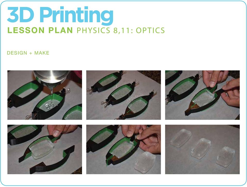
12 DESIGN + MAKE 3DP: CASTING STEP 3: Cast the lenses using gel wax. Before casting, you will need 2 binder clips for each mold, painter s tape, a sheet of parchment paper, and gel wax 1. Preheat oven to 230 F (110 C). 2. Cut some gel wax and place in a small, metal sauce pan or any other oven safe container. 3. Put pan/container in the oven and wait until gel wax has completed melted. 4. While waiting for the gel wax to melt, apply painter s tape to the inside of your molds. The painter s tape will make it easier for the lens to be removed from the molds later on. 5. Join the molds together by using binder clips to fasten the ends. Place completed mold on parchment paper. 6. When the gel wax has melted completely, take pan out of the oven and pour wax into the molds. 7. Let cool for 10 minutes. 8. When it looks like the wax has settled, unfasten the clips and gently peel the molds away from the gel. You should be left with a clear lens. 9. Clean up: instead of washing out any leftover wax, let the wax cool in the container and peel wax from container when cooled. Save wax for future use.

13 DESIGN + MAKE
14 EVALUATE STUDENT HANDOUT Optics Investigation Purpose: Materials: Ray boxes Rulers 5 gel wax lenses of varying curvature (NOTE: lenses should each have a radius of curvature that is at least 20mm larger or smaller than the other lenses to be tested). Procedure: 1. Set up the equipment as in Figure 1. The zero line of the ruler should line up with the imaginary centre line of the lens. towards lens. Observe where the beams of light converge after the light passes through the lens. This point is the focal point. 3. In table 1, record the measurement along the ruler as to how far the focal point is from the zero line. This is the focal length. ent radius of curvature. Repeat steps 1-3. Continue switching out lenses until all your lenses have been tested.

15 EVALUATE STUDENT HANDOUT Data Table 1 Radius of Curvature Focal Length Plots On a sheet of graph paper, plot a graph. The radius of curvature is displayed on the x-axis and the focal e plotted. Analysis 2. With reference to your graph, predict the focal length of a gel wax lens with a radius of curvature of: (a) 15mm, (b) 95mm, and (c) 105mm 3. A gel-wax lens of unknown radius of curvature is tested and the focal length is measured at 2.7cm. What is the radius of curvature of the lens? 4. After light beams pass through your gel-wax lens, the light beams may not be as sharp as before (that is, they may tend to spread out more). What is the cause of this spreading?

16 ADAPT APPLICATION Compound microscopes use a system of 2 or more lenses to magnify objects. Refer to the following instructions on how to build and modify your own microscope (click this link), and use what you have learned from this lesson to design and cast the necessary lenses. FUTURE STUDY Using what you have learned from this lesson, design and cast your own lenses to test the following: 1. What happens to light rays as they pass through double concave lenses or lenses that are asymmetrical such as concavo-convex and plano-concave lenses? 2. Compared to gel-wax lenses, would the focal length be longer or shorter if the lenses were made of Jell-O or Ice? 3. How would focal length change if the width of each gel-wax lens were made shorter or longer?

SpaceClaim Introduction Training Session. A SpaceClaim Support Document
 SpaceClaim Introduction Training Session A SpaceClaim Support Document In this class we will walk through the basic tools used to create and modify models in SpaceClaim. Introduction We will focus on:
Geometric Optics Converging Lenses and Mirrors Physics Lab IV
 Objective Geometric Optics Converging Lenses and Mirrors Physics Lab IV In this set of lab exercises, the basic properties geometric optics concerning converging lenses and mirrors will be explored. The
Getting Started in Tinkercad
 Getting Started in Tinkercad By Bonnie Roskes, 3DVinci Tinkercad is a fun, easy to use, web-based 3D design application. You don t need any design experience - Tinkercad can be used by anyone. In fact,
Lesson 29: Lenses. Double Concave. Double Convex. Planoconcave. Planoconvex. Convex meniscus. Concave meniscus
 Lesson 29: Lenses Remembering the basics of mirrors puts you half ways towards fully understanding lenses as well. The same sort of rules apply, just with a few modifications. Keep in mind that for an
What s New V 11. Preferences: Parameters: Layout/ Modifications: Reverse mouse scroll wheel zoom direction
 What s New V 11 Preferences: Reverse mouse scroll wheel zoom direction Assign mouse scroll wheel Middle Button as Fine tune Pricing Method (Manufacturing/Design) Display- Display Long Name Parameters:
MARS STUDENT IMAGING PROJECT
 MARS STUDENT IMAGING PROJECT Data Analysis Practice Guide Mars Education Program Arizona State University Data Analysis Practice Guide This set of activities is designed to help you organize data you collect
waves rays Consider rays of light from an object being reflected by a plane mirror (the rays are diverging): mirror object
: mirror object") PHYS1000 Optics 1 Optics Light and its interaction with lenses and mirrors. We assume that we can ignore the wave properties of light. waves rays We represent the light as rays, and ignore diffraction.
PHYS1000 Optics 1 Optics Light and its interaction with lenses and mirrors. We assume that we can ignore the wave properties of light. waves rays We represent the light as rays, and ignore diffraction.
Reflection and Refraction
 Equipment Reflection and Refraction Acrylic block set, plane-concave-convex universal mirror, cork board, cork board stand, pins, flashlight, protractor, ruler, mirror worksheet, rectangular block worksheet,
Create a Poster Using Publisher
 Contents 1. Introduction 1. Starting Publisher 2. Create a Poster Template 5. Aligning your images and text 7. Apply a background 12. Add text to your poster 14. Add pictures to your poster 17. Add graphs
Procedure: Geometrical Optics. Theory Refer to your Lab Manual, pages 291 294. Equipment Needed
 Theory Refer to your Lab Manual, pages 291 294. Geometrical Optics Equipment Needed Light Source Ray Table and Base Three-surface Mirror Convex Lens Ruler Optics Bench Cylindrical Lens Concave Lens Rhombus
Introduction to Autodesk Inventor for F1 in Schools
 F1 in Schools race car Introduction to Autodesk Inventor for F1 in Schools In this course you will be introduced to Autodesk Inventor, which is the centerpiece of Autodesk s Digital Prototyping strategy
TABLE OF CONTENTS. INTRODUCTION... 5 Advance Concrete... 5 Where to find information?... 6 INSTALLATION... 7 STARTING ADVANCE CONCRETE...
 Starting Guide TABLE OF CONTENTS INTRODUCTION... 5 Advance Concrete... 5 Where to find information?... 6 INSTALLATION... 7 STARTING ADVANCE CONCRETE... 7 ADVANCE CONCRETE USER INTERFACE... 7 Other important
Introduction to Autodesk Inventor for F1 in Schools
 Introduction to Autodesk Inventor for F1 in Schools F1 in Schools Race Car In this course you will be introduced to Autodesk Inventor, which is the centerpiece of Autodesk s digital prototyping strategy
Convex Mirrors. Ray Diagram for Convex Mirror
 Convex Mirrors Center of curvature and focal point both located behind mirror The image for a convex mirror is always virtual and upright compared to the object A convex mirror will reflect a set of parallel
AP Physics B Ch. 23 and Ch. 24 Geometric Optics and Wave Nature of Light
 AP Physics B Ch. 23 and Ch. 24 Geometric Optics and Wave Nature of Light Name: Period: Date: MULTIPLE CHOICE. Choose the one alternative that best completes the statement or answers the question. 1) Reflection,
 Edinburgh COLLEGE of ART ARCHITECTURE 3D Modelling in AutoCAD - tutorial exercise The screen The graphics area This is the part of the screen in which the drawing will be created. The command prompt area
Chapter 36 - Lenses. A PowerPoint Presentation by Paul E. Tippens, Professor of Physics Southern Polytechnic State University
 Chapter 36 - Lenses A PowerPoint Presentation by Paul E. Tippens, Professor of Physics Southern Polytechnic State University 2007 Objectives: After completing this module, you should be able to: Determine
Thin Lenses Drawing Ray Diagrams
 Drawing Ray Diagrams Fig. 1a Fig. 1b In this activity we explore how light refracts as it passes through a thin lens. Eyeglasses have been in use since the 13 th century. In 1610 Galileo used two lenses
2013 Getting Started Guide
 2013 Getting Started Guide The contents of this guide and accompanying exercises were originally created by Nemetschek Vectorworks, Inc. Vectorworks Fundamentals Getting Started Guide Created using: Vectorworks
1051-232 Imaging Systems Laboratory II. Laboratory 4: Basic Lens Design in OSLO April 2 & 4, 2002
 05-232 Imaging Systems Laboratory II Laboratory 4: Basic Lens Design in OSLO April 2 & 4, 2002 Abstract: For designing the optics of an imaging system, one of the main types of tools used today is optical
Basic AutoSketch Manual
 Basic AutoSketch Manual Instruction for students Skf-Manual.doc of 3 Contents BASIC AUTOSKETCH MANUAL... INSTRUCTION FOR STUDENTS... BASIC AUTOSKETCH INSTRUCTION... 3 SCREEN LAYOUT... 3 MENU BAR... 3 FILE
Understand the Sketcher workbench of CATIA V5.
 Chapter 1 Drawing Sketches in Learning Objectives the Sketcher Workbench-I After completing this chapter you will be able to: Understand the Sketcher workbench of CATIA V5. Start a new file in the Part
Basic Optics System OS-8515C
 40 50 30 60 20 70 10 80 0 90 80 10 20 70 T 30 60 40 50 50 40 60 30 C 70 20 80 10 90 90 0 80 10 70 20 60 50 40 30 Instruction Manual with Experiment Guide and Teachers Notes 012-09900B Basic Optics System
Excel -- Creating Charts
 Excel -- Creating Charts The saying goes, A picture is worth a thousand words, and so true. Professional looking charts give visual enhancement to your statistics, fiscal reports or presentation. Excel
SketchUp Instructions
 SketchUp Instructions Every architect needs to know how to use SketchUp! SketchUp is free from Google just Google it and download to your computer. You can do just about anything with it, but it is especially
2) A convex lens is known as a diverging lens and a concave lens is known as a converging lens. Answer: FALSE Diff: 1 Var: 1 Page Ref: Sec.
 A convex lens is known as a diverging lens and a concave lens is known as a converging lens. Answer: FALSE Diff: 1 Var: 1 Page Ref: Sec.") Physics for Scientists and Engineers, 4e (Giancoli) Chapter 33 Lenses and Optical Instruments 33.1 Conceptual Questions 1) State how to draw the three rays for finding the image position due to a thin
Physics for Scientists and Engineers, 4e (Giancoli) Chapter 33 Lenses and Optical Instruments 33.1 Conceptual Questions 1) State how to draw the three rays for finding the image position due to a thin
Light and its effects
 Light and its effects Light and the speed of light Shadows Shadow films Pinhole camera (1) Pinhole camera (2) Reflection of light Image in a plane mirror An image in a plane mirror is: (i) the same size
LIGHT SECTION 6-REFRACTION-BENDING LIGHT From Hands on Science by Linda Poore, 2003.
 LIGHT SECTION 6-REFRACTION-BENDING LIGHT From Hands on Science by Linda Poore, 2003. STANDARDS: Students know an object is seen when light traveling from an object enters our eye. Students will differentiate
Revision problem. Chapter 18 problem 37 page 612. Suppose you point a pinhole camera at a 15m tall tree that is 75m away.
 Revision problem Chapter 18 problem 37 page 612 Suppose you point a pinhole camera at a 15m tall tree that is 75m away. 1 Optical Instruments Thin lens equation Refractive power Cameras The human eye Combining
Lecture 17. Image formation Ray tracing Calculation. Lenses Convex Concave. Mirrors Convex Concave. Optical instruments
 Lecture 17. Image formation Ray tracing Calculation Lenses Convex Concave Mirrors Convex Concave Optical instruments Image formation Laws of refraction and reflection can be used to explain how lenses
EXPERIMENT 6 OPTICS: FOCAL LENGTH OF A LENS
 EXPERIMENT 6 OPTICS: FOCAL LENGTH OF A LENS The following website should be accessed before coming to class. Text reference: pp189-196 Optics Bench a) For convenience of discussion we assume that the light
Guide To Creating Academic Posters Using Microsoft PowerPoint 2010
 Guide To Creating Academic Posters Using Microsoft PowerPoint 2010 INFORMATION SERVICES Version 3.0 July 2011 Table of Contents Section 1 - Introduction... 1 Section 2 - Initial Preparation... 2 2.1 Overall
Science In Action 8 Unit C - Light and Optical Systems. 1.1 The Challenge of light
 1.1 The Challenge of light 1. Pythagoras' thoughts about light were proven wrong because it was impossible to see A. the light beams B. dark objects C. in the dark D. shiny objects 2. Sir Isaac Newton
Linkage 3.2. User s Guide
 Linkage 3.2 User s Guide David Rector Wednesday, April 06, 2016 Table of Contents Table of Contents... 2 Installation... 3 Running the Linkage Program... 3 Simple Mechanism Tutorial... 5 Mouse Operations...
Laws; of Refraction. bends away from the normal. more dense medium bends towards the normal. to another does not bend. It is not
 Science 8 Laws; of Refraction 1. tight that moyes at an angle from a less dense medium to a more dense medium bends towards the normal. (The second medium slows the light down) Note: The angle of refraction,
1. You stand two feet away from a plane mirror. How far is it from you to your image? a. 2.0 ft c. 4.0 ft b. 3.0 ft d. 5.0 ft
 Lenses and Mirrors 1. You stand two feet away from a plane mirror. How far is it from you to your image? a. 2.0 ft c. 4.0 ft b. 3.0 ft d. 5.0 ft 2. Which of the following best describes the image from
SAP2000 Getting Started Tutorial
 SAP2000 Getting Started Tutorial Learn how to define materials, sections, grids, and supports with basic modeling concepts for creating and modifying a concrete bent structure model using a nonprismatic
GUIDELINES FOR PREPARING POSTERS USING POWERPOINT PRESENTATION SOFTWARE
 Society for the Teaching of Psychology (APA Division 2) OFFICE OF TEACHING RESOURCES IN PSYCHOLOGY (OTRP) Department of Psychology, Georgia Southern University, P. O. Box 8041, Statesboro, GA 30460-8041
PowerPoint: Graphics and SmartArt
 PowerPoint: Graphics and SmartArt Contents Inserting Objects... 2 Picture from File... 2 Clip Art... 2 Shapes... 3 SmartArt... 3 WordArt... 3 Formatting Objects... 4 Move a picture, shape, text box, or
Chapter 17: Light and Image Formation
 Chapter 17: Light and Image Formation 1. When light enters a medium with a higher index of refraction it is A. absorbed. B. bent away from the normal. C. bent towards from the normal. D. continues in the
Lesson 26: Reflection & Mirror Diagrams
 Lesson 26: Reflection & Mirror Diagrams The Law of Reflection There is nothing really mysterious about reflection, but some people try to make it more difficult than it really is. All EMR will reflect
Rutgers Analytical Physics 750:228, Spring 2016 ( RUPHY228S16 )
") 1 of 13 2/17/2016 5:28 PM Signed in as Weida Wu, Instructor Help Sign Out Rutgers Analytical Physics 750:228, Spring 2016 ( RUPHY228S16 ) My Courses Course Settings University Physics with Modern Physics,
1 of 13 2/17/2016 5:28 PM Signed in as Weida Wu, Instructor Help Sign Out Rutgers Analytical Physics 750:228, Spring 2016 ( RUPHY228S16 ) My Courses Course Settings University Physics with Modern Physics,
Applying a circular load. Immediate and consolidation settlement. Deformed contours. Query points and query lines. Graph query.
 Quick Start Tutorial 1-1 Quick Start Tutorial This quick start tutorial will cover some of the basic features of Settle3D. A circular load is applied to a single soil layer and settlements are examined.
HOMEWORK 4 with Solutions
 Winter 996 HOMEWORK 4 with Solutions. ind the image of the object for the single concave mirror system shown in ig. (see next pages for worksheets) by: (a) measuring the radius R and calculating the focal
Autodesk Fusion 360 Badge Guide: Design an F1 in Schools Trophy
 Autodesk Fusion 360 Badge Guide: Design an F1 in Schools Trophy Abstract: Gain basic understanding of creating 3D models in Fusion 360 by designing an F1 in Schools trophy. This badge may be claimed by
Introduction to CATIA V5
 Introduction to CATIA V5 Release 16 (A Hands-On Tutorial Approach) Kirstie Plantenberg University of Detroit Mercy SDC PUBLICATIONS Schroff Development Corporation www.schroff.com www.schroff-europe.com
Blender Notes. Introduction to Digital Modelling and Animation in Design Blender Tutorial - week 9 The Game Engine
 Blender Notes Introduction to Digital Modelling and Animation in Design Blender Tutorial - week 9 The Game Engine The Blender Game Engine This week we will have an introduction to the Game Engine build
Creating Drawings in Pro/ENGINEER
 6 Creating Drawings in Pro/ENGINEER This chapter shows you how to bring the cell phone models and the assembly you ve created into the Pro/ENGINEER Drawing mode to create a drawing. A mechanical drawing
SolidWorks Tutorial 4 CANDLESTICK
 SolidWorks Tutorial 4 CANDLESTICK Candlestick In this tutorial you will make a simple container and a candlestick out of sheetmetal. You will learn about working with sheet metal in SolidWorks. We will
Creating a Poster in Powerpoint
 Creating a Poster in Powerpoint January 2013 Contents 1. Starting Powerpoint 2. Setting Size and Orientation 3. Display a Grid 5. Apply a background 7. Add text to your poster 9. Add WordArt to your poster
Technical Drawing Specifications Resource A guide to support VCE Visual Communication Design study design 2013-17
 A guide to support VCE Visual Communication Design study design 2013-17 1 Contents INTRODUCTION The Australian Standards (AS) Key knowledge and skills THREE-DIMENSIONAL DRAWING PARALINE DRAWING Isometric
Using Excel to find Perimeter, Area & Volume
 Using Excel to find Perimeter, Area & Volume Level: LBS 4 V = lwh Goal: To become familiar with Microsoft Excel by entering formulas into a spreadsheet in order to calculate the perimeter, area and volume
Geometrical Optics - Grade 11
 OpenStax-CNX module: m32832 1 Geometrical Optics - Grade 11 Rory Adams Free High School Science Texts Project Mark Horner Heather Williams This work is produced by OpenStax-CNX and licensed under the Creative
3D-GIS in the Cloud USER MANUAL. August, 2014
 3D-GIS in the Cloud USER MANUAL August, 2014 3D GIS in the Cloud User Manual August, 2014 Table of Contents 1. Quick Reference: Navigating and Exploring in the 3D GIS in the Cloud... 2 1.1 Using the Mouse...
Chapter 1. Creating Sketches in. the Sketch Mode-I. Evaluation chapter. Logon to www.cadcim.com for more details. Learning Objectives
 Chapter 1 Creating Sketches in Learning Objectives the Sketch Mode-I After completing this chapter you will be able to: Use various tools to create a geometry. Dimension a sketch. Apply constraints to
Computer Basics: Tackling the mouse, keyboard, and using Windows
 Computer Basics: Tackling the mouse, keyboard, and using Windows Class Description: Interested in learning how to use a computer? Come learn the computer basics at the Muhlenberg Community Library. This
C) D) As object AB is moved from its present position toward the left, the size of the image produced A) decreases B) increases C) remains the same
 D) As object AB is moved from its present position toward the left, the size of the image produced A) decreases B) increases C) remains the same") 1. For a plane mirror, compared to the object distance, the image distance is always A) less B) greater C) the same 2. Which graph best represents the relationship between image distance (di) and object
1. For a plane mirror, compared to the object distance, the image distance is always A) less B) greater C) the same 2. Which graph best represents the relationship between image distance (di) and object
COOL ART WITH MATH & SCIENCE OPTICAL ILLUSIONS CREATIVE ACTIVITIES THAT MAKE MATH & SCIENCE FUN FOR KIDS! A NDERS HANSON AND ELISSA MANN
 CHECKERBOARD HOW-TO LIBRARY COOL ART WITH MATH & SCIENCE OPTICAL ILLUSIONS CREATIVE ACTIVITIES THAT MAKE MATH & SCIENCE FUN FOR KIDS! A NDERS HANSON AND ELISSA MANN C O O L A R T W I T H M A T H & S C
Lesson 7 - Creating Animation II
 Lesson 7 - Creating Animation II A. Motion-Tweened Animation With motion tweening, you can easily create motion effects for the objects in your Flash movies. Kites flying, balls bouncing, rocks rolling
2. More Use of the Mouse in Windows 7
 65 2. More Use of the Mouse in Windows 7 The mouse has become an essential part of the computer. But it is actually a relatively new addition. The mouse did not become a standard part of the PC until Windows
10. THERM DRAWING TIPS
 10. THERM DRAWING TIPS 10.1. Drawing Tips The THERM User's Manual describes in detail how to draw cross-sections in THERM. This section of the NFRC Simualation Training Manual presents some additional
Pro/ENGINEER Wildfire 5.0 Introduction to Surface Modeling
 Introduction Several advanced surface types are available as listed below. Variable Section Sweep Boundary Blend Section to Surfaces Blend Surface to Surface Blend A surface is created by sweeping a single
Creating Smart Models From Scan Data
 Rapidform Tech Tip Creating Smart Models From Scan Data Related Product Version Rapidform XOR3 Goal To create a smart model from scan data. A smart model is a parametric model that uses parameters intelligently
Statgraphics Getting started
 Statgraphics Getting started The aim of this exercise is to introduce you to some of the basic features of the Statgraphics software. Starting Statgraphics 1. Log in to your PC, using the usual procedure
GeoGebra. 10 lessons. Gerrit Stols
 GeoGebra in 10 lessons Gerrit Stols Acknowledgements GeoGebra is dynamic mathematics open source (free) software for learning and teaching mathematics in schools. It was developed by Markus Hohenwarter
Third Grade Light and Optics Assessment
 Third Grade Light and Optics Assessment 1a. Light travels at an amazingly high speed. How fast does it travel? a. 186,000 miles per second b. 186,000 miles per hour 1b. Light travels at an amazingly high
SMART Board Tips & Tricks (version 9.0) Getting Started. SMART Tools vs. SMART Notebook software
 Getting Started. SMART Tools vs. SMART Notebook software") SMART Board Tips & Tricks (version 9.0) Getting Started SMART Tools vs. SMART Notebook software Click the SMART Board icon (in the system tray at the bottom right of your screen) to access the SMART Board
SMART Board Tips & Tricks (version 9.0) Getting Started SMART Tools vs. SMART Notebook software Click the SMART Board icon (in the system tray at the bottom right of your screen) to access the SMART Board
The CAD interface is comprised of two different screens: the graphic/drawing screen and the text screen.
 That CAD Girl J ennifer dib ona Website: www.thatcadgirl.com Email: [email protected] Phone: (919) 417-8351 Fax: (919) 573-0351 Overview of AutoCAD or IntelliCAD with Carlson Software Screens and
USING ADOBE PhotoShop TO MEASURE EarthKAM IMAGES
 USING ADOBE PhotoShop TO MEASURE EarthKAM IMAGES By James H. Nicholson and Ellen Vaughan Charleston County School District CAN DO Project for the EarthKAM Teacher Training Institute Introduction EarthKAM
Getting Started With DraftSight A Guide For AEC Users
 Getting Started With DraftSight A Guide For AEC Users DraftSight.com Facebook.com/DraftSight Welcome to DraftSight a valuable tool for any AEC professional! DraftSight is more than a free, professional-grade
How to make a line graph using Excel 2007
 How to make a line graph using Excel 2007 Format your data sheet Make sure you have a title and each column of data has a title. If you are entering data by hand, use time or the independent variable in
Experiment 3 Lenses and Images
 Experiment 3 Lenses and Images Who shall teach thee, unless it be thine own eyes? Euripides (480?-406? BC) OBJECTIVES To examine the nature and location of images formed by es. THEORY Lenses are frequently
Lesson Four 3D Modeling
 Lesson Four 3D Modeling In this lesson you will learn how to: Easily Rotate the UCS to model in different planes Model lines in a method similar to drawing isometrics Create 3D Router Lines Automatically
Convert between units of area and determine the scale factor of two similar figures.
 CHAPTER 5 Units of Area c GOAL Convert between units of area and determine the scale factor of two. You will need a ruler centimetre grid paper a protractor a calculator Learn about the Math The area of
9/16 Optics 1 /11 GEOMETRIC OPTICS
 9/6 Optics / GEOMETRIC OPTICS PURPOSE: To review the basics of geometric optics and to observe the function of some simple and compound optical devices. APPARATUS: Optical bench, lenses, mirror, target
MET 306 Activity 6. Using Pro/MFG Milling Operations Creo 2.0. Machining a Mast Step
 Using Pro/MFG Milling Operations Creo 2.0 Machining a Mast Step If the Trim option is grayed out when trimming the mill volume, Save (making sure the.asm file is going to the correct subdirectory), Exit
Grazing incidence wavefront sensing and verification of X-ray optics performance
 Grazing incidence wavefront sensing and verification of X-ray optics performance Timo T. Saha, Scott Rohrbach, and William W. Zhang, NASA Goddard Space Flight Center, Greenbelt, Md 20771 Evaluation of
Flash MX 2004 Animation Lesson
 Flash MX 2004 Animation Lesson By Tonia Malone Technology & Learning Services 14-102 Lesson Opening a document To open an existing document: 1. Select File > Open. 2. In the Open dialog box, navigate to
Light and Sound. Pupil Booklet
 Duncanrig Secondary School East Kilbride S2 Physics Elective Light and Sound Name: Pupil Booklet Class: SCN 3-11a - By exploring the refraction of light when passed through different materials, lenses
SDC. Schroff Development Corporation WWW.SDCACAD.COM PUBLICATIONS. MultiMedia CD by Jack Zecher
 MultiMedia CD by Jack Zecher An audioi/visual presentation of the tutorial exercises SDC PUBLICATIONS Schroff Development Corporation WWW.SDCACAD.COM AutoCAD 2002 Tutorial 2-1 Lesson 2 Geometric Construction
IES <Virtual Environment> Tutorial. ModelIT (Version 6.0)
") IES Tutorial ModelIT (Version 6.0) 1 Introduction: ModelIT Tutorial This document shows you how to use ModelIT, IES s 3D building geometry modelling tool. The tutorial is intended
IES Tutorial ModelIT (Version 6.0) 1 Introduction: ModelIT Tutorial This document shows you how to use ModelIT, IES s 3D building geometry modelling tool. The tutorial is intended
Chapter 9. Editing Features. Learning Objectives
 Chapter 9 Editing Features Learning Objectives After completing this chapter, you will be able to: Edit features. Edit sketches of the sketch based features. Edit the sketch plane of the sketch based features.
DISCLAIMER. This document was prepared as an account of work sponsored by an agency of the United States
 DISCLAIMER This document was prepared as an account of work sponsored by an agency of the United States Government. Neither the United States Government nor the University of California nor any of their
Tutorial for Tracker and Supporting Software By David Chandler
 Tutorial for Tracker and Supporting Software By David Chandler I use a number of free, open source programs to do video analysis. 1. Avidemux, to exerpt the video clip, read the video properties, and save
7.2. Focusing devices: Unit 7.2. context. Lenses and curved mirrors. Lenses. The language of optics
 context 7.2 Unit 7.2 ocusing devices: Lenses and curved mirrors Light rays often need to be controlled and ed to produce s in optical instruments such as microscopes, cameras and binoculars, and to change
ArchiCAD Tutorial Getting started. Dr. Benny Raphael Dept. of Building National University of Singapore (NUS)
") ArchiCAD Tutorial Getting started Dr. Benny Raphael Dept. of Building National University of Singapore (NUS) Launch ArchiCAD You can either create a new project or open an existing (previously saved) project.
ArchiCAD Tutorial Getting started Dr. Benny Raphael Dept. of Building National University of Singapore (NUS) Launch ArchiCAD You can either create a new project or open an existing (previously saved) project.
2014 Simplify3D. Quick Start Guide
 Quick Start Guide Preparation Installing Simplify3D Software 3 The Configuration Assistant 4 The Interface Layout 5 3D Printing Workflow Import Process Settings Preview Print! Import 7 Process Settings
4. CAMERA ADJUSTMENTS
 4. CAMERA ADJUSTMENTS Only by the possibility of displacing lens and rear standard all advantages of a view camera are fully utilized. These displacements serve for control of perspective, positioning
Creating Your Own 3D Models
 14 Creating Your Own 3D Models DAZ 3D has an extensive growing library of 3D models, but there are times that you may not find what you want or you may just want to create your own model. In either case
Creating a Poster in PowerPoint 2010. A. Set Up Your Poster
 View the Best Practices in Poster Design located at http://www.emich.edu/training/poster before you begin creating a poster. Then in PowerPoint: (A) set up the poster size and orientation, (B) add and
SolidWorks Tutorial 3 MAGNETIC BLOCK
 SolidWorks Tutorial 3 MAGNETIC BLOCK Magnetic Block In this exercise you will make a magnetic block. To do so, you will create a few parts, which you will assemble. You will learn the following new applications
Adobe Illustrator CS5 Part 1: Introduction to Illustrator
 CALIFORNIA STATE UNIVERSITY, LOS ANGELES INFORMATION TECHNOLOGY SERVICES Adobe Illustrator CS5 Part 1: Introduction to Illustrator Summer 2011, Version 1.0 Table of Contents Introduction...2 Downloading
CNC MILLING. University for Applied Arts, Vienna Studio Prof. Lynn Compiled by Nathalie Rinne With special thanks to David Erdman
 CNC MILLING GL Form Manufacturing Lab, photo: Stefan Hörner University for Applied Arts, Vienna Studio Prof. Lynn Compiled by Nathalie Rinne With special thanks to David Erdman Rules & Safety guidlines:
An introduction to 3D draughting & solid modelling using AutoCAD
 An introduction to 3D draughting & solid modelling using AutoCAD Faculty of Technology University of Plymouth Drake Circus Plymouth PL4 8AA These notes are to be used in conjunction with the AutoCAD software
Lenses and Telescopes
 A. Using single lenses to form images Lenses and Telescopes The simplest variety of telescope uses a single lens. The image is formed at the focus of the telescope, which is simply the focal plane of the
16 Circles and Cylinders
 16 Circles and Cylinders 16.1 Introduction to Circles In this section we consider the circle, looking at drawing circles and at the lines that split circles into different parts. A chord joins any two
Physics 202 Problems - Week 8 Worked Problems Chapter 25: 7, 23, 36, 62, 72
 Physics 202 Problems - Week 8 Worked Problems Chapter 25: 7, 23, 36, 62, 72 Problem 25.7) A light beam traveling in the negative z direction has a magnetic field B = (2.32 10 9 T )ˆx + ( 4.02 10 9 T )ŷ
NDSU Technology Learning & Media Center
 1 NDSU Technology Learning & Media Center QBB 150C 231-5130 www.ndsu.edu/its/tlmc Creating a Large Format Poster (Plot) Using PowerPoint 2013 Posters should be designed and created in a manner that best
How to build text and objects in the Titler
 How to build text and objects in the Titler You can use the Titler in Adobe Premiere Pro to create text and geometric objects. There are three methods for creating text, each capable of producing either
Interactive Voting System. www.ivsystem.nl. IVS-Basic IVS-Professional 4.4
 Interactive Voting System www.ivsystem.nl IVS-Basic IVS-Professional 4.4 Manual IVS-Basic 4.4 IVS-Professional 4.4 1213 Interactive Voting System The Interactive Voting System (IVS ) is an interactive