ARCHITECTURAL PRECAST CONCRETE ANCHORS
|
|
|
- Kristina Higgins
- 7 years ago
- Views:
Transcription


1 ARCHITECTURAL PRECAST CONCRETE ANCHORS FIXINOX BELGIUM / FRANCE / GULF AND MIDDLE EAST
2 INDEX 1. GENERAL DESCRIPTION OF THE FIXI 3D SYSTEM HANGER FIXI 3D (LOAD BEARING) HORIZONTAL LOAD CONNECTIONS AND CAVITY ADJUSTMENT WIND LOAD RESTRAINT ANCHOR LAYOUT AND IMPLEMENTING DIMENSIONS PARAPET ANCHORS PARAPET ANCHORS FIX BA...17 QUALITY FEATURES ARE : Simple and quick on site installation Dry fixing (cast in plate in the concrete structure not necessary) Adjustable in all directions EOTA approved All load bearing parts are manufactured in Stainless steel grade 316 (0 corrosion risk ) Cost factor improves with larger cavity thanks to less metal involved Heavy load bearing custom sized angles and concrete corbels are spared Reduced thermal bridging (thermal conductivity of stainless steel is 1/3 of normal steel conductivity+ 4 or 6 punctual fixings only for more than 15 square meters. BEWARE : OUR SOLUTIONS ARE CUSTOM MADE INFORMATION REQUESTED FOR QUOTATION Drawing of façade front view Number and size or precast panel Support specification (thickness of in situ concrete wall and floor or dimensions of metal beam) Cavity dimensions 1
 1 COMPRESSION ANCHOR (3) DOWEL")
 4 LOAD BEARING SUPPORTS WWW.FIXINOX.")
3 1. GENERAL DESCRIPTION OF THE FIXI 3D SYSTEM LOAD BEARING (1 & 2) 1 COMPRESSION ANCHOR (3) DOWEL RESTRAINT (5) 2 RESTRAINT ANCHOR COMPRESSION + TENSION (4) 4 LOAD BEARING SUPPORTS 2

4 2. HANGER FIXI 3D (LOAD BEARING) LOAD CAPACITY (kn) COLOR INDEX 5,0 8,0 11,5 16,0 22,0 27,0 1 1b 2 34,0 56,0 The hangers FIXI3D are the load bearing adjustable fixings. They are proposed on complete set or as spare items. Spare items as follows: a)upper section made of 316 sheets (1 to 5),b) assembly adjustable component (6), c) cast in insert (7) Each item of the hanger is painted of a special color in accordance with load capacity (see chart) For each load capacity 5 shapes of upper section are available. While the dimensions of the assembly component and of the insert are unique per load capacity. 2b TO 5 ARE UPPER UNIT 1 Single facing Hanger 2 Single Attika (Floor) Hanger 3 Dual forked facing Hanger 4 Dual straight facing Hanger 5 Dual Attika (Floor) Hanger 6 Assembly component 7 Cast in insert (Lower unit) 3
5 A B FIXI 3D SINGLE UPPER PART ARTICLES 04IM001 AND 04M010 HANGER COMPLETE HANGER ALONE OR UPPER UNIT LOAD CAPACITY (kn) CAVITY MINIMUM CONCRETEPANEL THICKNESS MINIMUM CONCRETE SUPPORT THICKNESS 04IM001-5,0 04MO10-5,0 5, IM001-8,0 04MO10-8,0 8, IM001-11,5 04MO10-11,5 11, IM001-16,0 A 04MO10-16,0 16, IM001-22,0 04MO10-22,0 22, IM001-27,0 04MO10-27,0 27, IM001-34,0 04MO10-34,0 34, IM001-56,0 B 04MO10-56,0 56, A B FIXI 3D SINGLE UPPER PART ARTICLES 04IM002 AND 04M015 04IM002-5,0 04MO15-5,0 5, IM002-8,0 04MO15-8,0 8, IM002-11,5 04MO15-11,5 11, IM002-16,0 A 04MO15-16,0 16, IM002-22,0 04MO15-22,0 22, IM002-27,0 04MO15-27,0 27, IM002-34,0 04MO15-34,0 34, IM002-56,0 B 04MO15-56,0 56,
6 TYPE SIZE AND NUMBER OF ANCHORING BOLTS ARE DESIGNED ACCORDING TO CONCRETE STRENGTH AND THICKNESS FIXI 3D DUAL UPPER UNIT (TWISTED) ARTICLES 04IM003 AND 04M020 HANGER COMPLETE HANGER ALONE OR UPPER UNIT LOAD CAPACITY (kn) MINIMUM CAVITY MINIMUM PANEL THICKNESS MINIMUM CONCRETE SUPPORT THICKNESS 04IM003-22,0 04MO20-22,0 22, IM003-27,0 04MO20-27,0 27, IM003-34,0 04MO20-34,0 34, FIXI 3D SINGLE UPPER PART (STRAIGHT) ARTICLES 04IM005 AND 04M026 04IM005-22,0 04MO26-22,0 22, IM005-27,0 04MO26-27,0 27, IM005-34,0 04MO26-34,0 34, IM005-56,0 04MO26-56,0 56, FIXI 3D DUAL UPPER UNIT ROOF TYPE (STRAIGHT) ARTICLES 04IM006 AND 04M027 04IM006-22,0 04MO27-22,0 22, IM006-27,0 04MO27-27,0 27, IM006-34,0 04MO27-34,0 34, IM006-56,0 04MO27-56,0 56,
7 ASSEMBLY COMPONENT 1 threaded rod,1 pin,1 nut and 1 square washer M THREAD THREADED ROD REF LOAD BEARING GRADE (kn) M THREAD PIN DIAMETER 04M035-5,0 5,0 M M035-8,0 8,0 M M035-11,5 11,5 M M035-16,0 16,0 M M035-22,0 22,0 M M035-27,0 27,0 M M035-34,0 34,0 M M035-56,0 56,0 M20 36 duplex INSERT The lower unit offers lateral adjustment. It includes one stainless steel bracket and a polystyrene former. The insert is sent to the precast panel fabricator. INSERT (LOWER UNIT) REF LOAD BEARING GRADE (kn) PANEL THICKNESS 04i030-5,0 5, i030-8,0 8, i030-11,5 11, i030-16,0 16, i030-22,0 22, i030-27,0 27, i030-34,0 34, i030-56,0 56,
8 REINFORCEMENT BARS The reinforcement loops and bars are in mild steel and are introduced by the precast fabricator through the insert. They avoid concrete cracking U SHAPED REINFORCEMENT BAR REINFORCEMENT BAR LOAD BEARING GRADE (kn) TOTAL LENGTH L 1 db1 ds1 TOTAL LENGTH L 2 ds2 L 3 h 5, Ø Ø , Ø Ø , Ø Ø , Ø Ø , Ø Ø , Ø Ø , Ø Ø , Ø Ø REQUIRED REINFORCEMENT min Lower unit (polystyrene) 2 U shaped bar 3 Reinforcement bar dmin

9 3. HORIZONTAL LOAD CONNECTIONS AND CAVITY ADJUSTMENT SPACER BOLT the support. It includes a threaded rod welded to a square stainless steel sheet. They consist of a threadhed rod and a welded square plate. The plate distributes the stresses on the concrete. The threaded rod is inserted into the precast panel in a plastic sleeve (Art N 04i031-xy). The nut allows easy adjustment of the depth of the cavity. The plastic sleeve is placed into the precast panel during manufacture, however it can be placed also in the in situ concrete wall. OTHER LENGTH ON REQUEST 1 Spacer bolt - Part no. 04M031 - M.. - L 2 Plastic sleeve - Part no. 04I031-M loads as a result of selfweight and wind forces. Tensile forces can not be taken. The use of the plastic sleeve is possible in the precast unit as well as in the insitu concrete wall. 8
 5,0 8,0 11,5 16,0 22,0 27,0 34,0 56,0 Standard compressive load in the spacer bolt (kn) 6,53 10,45 15,02 19,41 26,69 30,73 38,70 63,74 56,0 M30 34,0 M24 27,0 22,0 M20 16,0 M16")
10 Spacer selection is linked to the supported pressure and to the cavity. The supported pressure is linked to the load capacity according chart below with minimal thickness Ep. HANGER LOAD GRADE (kn) 5,0 8,0 11,5 16,0 22,0 27,0 34,0 56,0 Standard compressive load in the spacer bolt (kn) 6,53 10,45 15,02 19,41 26,69 30,73 38,70 63,74 56,0 M30 34,0 M24 27,0 22,0 M20 16,0 M16 11,5 M12 8,0 M10 5,0 Ep NON SHRINKING GROOT DOWEL RESTRAINT Vertical pinning secures two superposed panels by means of the sealed pin in the edge of the two plates. They usually consist of: edge of the upper plate inner diameter 12, 16, 20; lower plate. For dia 12 and 16 pins inner cross section is 22x47 mm; For dia 20 inner cross section is 35x60 mm; the cylindrical sleeve (single pinning); 9
.")
11 3.2 WIND LOAD RESTRAINT ANCHOR The choice of a category of wind load restraint anchor wich is generally located at the bottom of a plate is directly related to the in situ erection conditions. FLAT WIND LOAD RESTRAINT ANCHOR The flat wind load restraint anchor comprises a plate having an oval button hole, a cylindric hole and a round bar welded on the rear (in situ wall side). It is fixed to the in situ wall by means of an xpansion bolt through the oval hole. A hex head screw passes through the cylindric hole and is fixed to the facing precast panel by means of a socket. The diameter of the round welded bar is equal to the height of the screw head. ARTICLE REF M THREAD WIND LOAD (kn) 04IM070 M10 1,8 04IM070 M12 3,0 04IM070 M16 4,2 TOOTHED C CHANNELS WIND LOAD RESTRAINT ANCHOR The principle of anchoring "wind" by C channels is to connect 2 channels with a hook Bracket welded seals on the respective sides of the structure and the with a toothed anchor plate inside the ventiladed space, the two channels being mutually orthogonal. The adjustable connection, in position and lenght, can be done in different ways, all parts being always stainless steel. And the connection setting is carried out by means of two plates held in the rack rails by notches or hammer screw fixed to the plate by welding. 10
12 TOOTHED ANCHOR AS TENSILE- AND COMPRESSIVE-SECURE CONNECTION TOOTHED ANCHOR WITH WELDED ON HOOK-HEAD SCREW POS LOAD RATING 8,0 kn (TENSILE/COMPRESSIVE FORCE) LOAD RATING 12,0 kn (TENSILE/COMPRESSIVE FORCE) 1 C-channel, type 40/25/150 Part no. 07FTA Hook-head bolt M16x40, type 40/22, Part no. 07FTB with toothed plate 30x30x4mm 3 Toothed anchor 35x6mm (max. e = 90mm)* or 35x8mm with welded on hook-head screw, Parti no. 03HKFP-800-L L = e max. e = 220 mm* C-channel, type 38/17/150 Part no. 07FTA Hook-head bolt M16x50, type 50/30, Part no. 07FTB with toothed plate 30x30x4mm Toothed anchor 35x8mm (max. e = 90mm)* or 35x10mm with welded on hook-head screw, Part no. 03HKFP-1200-L L = e a r 100 mm 150 mm * for bigger e-values the permitted pressure values must be reduced if necessary - only on request! 11
13 4. LAYOUT AND IMPLEMENTING DIMENSIONS LAYOUT OF SPACER BOLT + WIND LOAD RESTRAINT ANCHOR Spacer bolt M diameter is related to load grade of panel hanger. Ep is the precast panel thickness. M12 M16 M20 M24 EP AR L/4 ar mm ar L L/4 ar SPACER BOLT mm ar L 12
14 EYEBOLT (ASSEMBLY COMPONENT) The thickness of the concrete panel (Ep) and the minimum thickness of the cavity (Ev) must be combined with the type of selected upper unit. The minimum values of these dimensions are given with the description of the unit page 7, 8 and 9. H1 dimension and the minimum length (L) of the assembly components (eye pin) are given in the table in the chart. CAVITY EV Capacity ,5 single 0,8 single 11,5 single 16,0 single 22,0 single 22,0 double straight 22,0 double twisted 27,0 simple 27,0 double straight 27,0 double twisted 34,0 simple 34,0 double straight 34,0 double twisted 56,0 simple 56,0 double straight L H L H L H L H L H L H L H L H L H L H L H L H L H L H L H
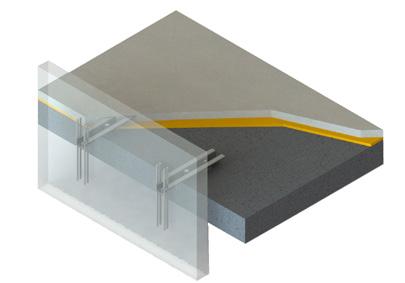
15 FORM AIDS, PROPOSAL FOR FACING PANEL ANCHOR A D D I 3 2 C A Side form on gable-end of facing panel unit 3 Reinforcement bar (see page 8) C Form base D Wooden cover I Insert 2 U shaped reinforcement bar (2 pieces) (see page 8) the wooden cover (C). The wooden cover must be at least as wide as the recess plug. The lower unit is similary to be protected against soiling. replaced by a stable section running continuously between the side forms comprising a wooden or steel cross-section. 14
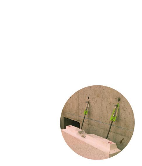
16 5. PARAPET ANCHORS Parapet anchor, with adjustement screw, standard unit, Part no. 04BA203- Md -L Parapet anchor, with adjustement screw, roof unit, Part no. 04BA205- Md -L 15
17 Parapet anchors allow fixing of concrete facades in parapet and roof areas. They absorb moments resulting from self-weight as well as wind pressure and suction. Parapet anchors are adjustable into 3 dimensions further anchorage and fixing gear, e.g.; additional tensile or compression anchors are not necessary. At least two parapet anchors are to be arranged per facing unit. Statically determined dimensions are preferred. To absorb the length changes of the completed unit resulting from temperature influences, a damper strip (5 mm polystyrene) is laid next to the parapet anchor. This damper strip is useless when the anchor is not in bedded in the concrete of the floor. PART NO. BA L BA L BA L BA L BA L BA L BA L BA L BA L BA L BA L BA L adm. MD kncm , ,5 I mm h mm b1 mm b2 mm , S mm d min mm REINFORCEMENT BARS ds mm I1 mm OTHER MEASUREMENTS a min mm t b mm e mm d L mm Other load ratings available on request. 16
18 6. PARAPET ANCHORS FIX BA DESIGN BASIC RULES OMEGA BA Parapet Anchors are dimensioned according to present standards and rules. Basic rules: Partial safety factor: G = 1.35 (dead load) Q = 1.50 (live load) The required OMEGA BA is chosen by calculating the bending moment, Md and the shear load, V at bearing point, A. ADDITIONNAL CHECK Check for serviceability At cases, additional verifications have to be taken into account: situations. CALCULATION OF LOADS Applied Loads A k (kn.m -1 ) Overload G k (kn.m -1 ) Weight of the parapet panel H k (kn.m -1 ) Point Load W k (kn.m -2 ) Wind load on the parapet panel Resultant Load and support reaction M d (knm) Calculation value for bending moment V d (kn) Calculation value for shear load N d (kn) Calculation value for normal load E d (kn) Calculation value for traction support reaction D d (kn) Calculation value for compression support reaction H k A k G k W k M d, A A N d, A E d D d V d, A 17
19 6.2 PARAPET ANCHORS FIX BA CALCULATION NOTE Shear Load V d = γ G G k + γ Q A k Normal Load N d = γ Q H k + γ Q W k Lever arms: w = e + 0,5f + 50mm e = distance between parapet and the edge of the slab f = thickness of parapet panel h W = centre of the parapet panel top of the slab h H = point load position (Note: point load may be applied at the upper edge of parapet) top of the slab Bending moment The largest bending moment on the parapet corbel occurs on the front support point: M d = γ G (A k + G k ) w +γ Q H k h H + γ Q W k h W M d,adm = M d /n With n = numbers of parapet anchors per panel, n > 2 SETTING UP PRESCRIPTIONS OMEGA BA Repartition OMEGA BA have to be set depending on the element gravity center so that it guarantee an equal stress for both OMEGA. OMEGA gathering may be possible under conditions. Horizontal Stress If the horizontal stress cannot be undertaken by the friction between the profile and the bearing area, the installation of toothed plates can solve this issue. OMEGAFIX Installation and adjustment Adjustment at the bearing area is made by use of appropriate wedges. Wide between OMEGA BA and the slab must be filled with a shrinkage compensated bearing mortar. 18
 info@fixinox.")
20 21 rue Jean-Pierre Timbaud Paris Île-de-France agency - Tel : +33 (0) North, East, South-East, international : +33 (0) Fax : +32 (0) Z.I. de Jumet Première rue, Jumet (Charleroi) info@fixinox.be FIXINOX HAS CONTRIBUTED TO EXCEPTIONAL SITES Hôpital Rothschild PARIS Boulevard Central DUBAI Rue Yves Kermen BOULOGNE BILLANCOURT The Lofts DUBAI
Diameter. Swift Lift Round Recess Plug. Note: The diameter of the narrow recess plug is the same as the diameter of the round recess plug.
 P-5 The P-5 is hot forged from carbon steel. The formed head provis spherical seating that the Lifting Eye engages, while a disc-shaped foot is embedd in the concrete. Due to its being a forged part, the
HORIZONTAL INSTALLATION
 THERMO/SOLAR Žiar s.r.o. MANUAL FOR INSTALLATION PV SUPPORTING FRAMES HORIZONTAL INSTALLATION Technical alternation reserved A1410 1 12/2014 CONTENT ORD.NO. PAGE Mounting information 3 Mounting, flat roof
DESIGN OF SLABS. 3) Based on support or boundary condition: Simply supported, Cantilever slab,
 Based on support or boundary condition: Simply supported, Cantilever slab,") DESIGN OF SLABS Dr. G. P. Chandradhara Professor of Civil Engineering S. J. College of Engineering Mysore 1. GENERAL A slab is a flat two dimensional planar structural element having thickness small compared
DESIGN OF SLABS Dr. G. P. Chandradhara Professor of Civil Engineering S. J. College of Engineering Mysore 1. GENERAL A slab is a flat two dimensional planar structural element having thickness small compared
Installation guide for the SafeLine type anchorage device. Tested in compliance with EN 795: 1996. No.: SE-...
 Installation guide for the SafeLine type anchorage device Tested in compliance with EN 795: 1996 No.: SE-... Version: 09.10.2008 SE 67 Subject to technical alterations! Contents 1. General information
Technical handbook Panel Anchoring System
 1 Basic principles of sandwich panels 3 Design conditions 4 Basic placement of anchors and pins 9 Large elements (muliple rows) 10 Small elements (two rows) 10 Turned elements 10 Slender elements 10 Cantilevering
It's large enough to handle most welding job shop projects, yet small enough to make it a worth while home-workshop tool
 It's large enough to handle most welding job shop projects, yet small enough to make it a worth while home-workshop tool H Craft Print Project No. 272 ERE'S a metal bender that will enable you to bend
Page 1 of 18 28.4.2008 Sven Alexander Last revised 1.3.2010. SB-Produksjon STATICAL CALCULATIONS FOR BCC 250
 Page 1 of 18 CONTENT PART 1 BASIC ASSUMPTIONS PAGE 1.1 General 1. Standards 1.3 Loads 1. Qualities PART ANCHORAGE OF THE UNITS.1 Beam unit equilibrium 3. Beam unit anchorage in front..1 Check of capacity..
SECTION 26 05 49 VIBRATION AND SEISMIC CONTROLS FOR ELECTRICAL SYSTEMS
 SECTION 26 05 49 VIBRATION AND SEISMIC CONTROLS FOR ELECTRICAL SYSTEMS PART 1 - GENERAL 1.1 SUMMARY A. This Section includes seismic restraints and other earthquake-damage-reduction measures for electrical
MultiPost-AP anchorage device
 MultiPost-AP anchorage device MultiPost anchorage point Type 1 Fixing on reinforced concrete with large, 360 rotating stainless steel lifting eye for the simultaneous securing of max. 2 persons. This can
Owner's Manual & Assembly Instructions
 Owner's Manual & Assembly Instructions PM01 BASE KIT Model No. FDN1014 717090311 CAUTION: SOME PARTS HAVE SHARP EDGES. CARE MUST BE TAKEN WHEN HANDLING THE VARIOUS PIECES TO AVOID A MISHAP. FOR SAFETY
Removable Aluminium posts
 Post Solent Sail Shades Ltd 120 Billington Gardens Hedge End Southampton SO30 2RT Tel/Fax: 01489 788243 www.solentsailshades.co.uk Email: info@solentsailshades.co.uk Removable Aluminium posts Single Pole
C O N V E Y O R C O M P O N E N T S C H A I N S B E L T S B E A R I N G S
 C O N V E Y O R C O M P O N E N T S C H A I N S B E L T S B E A R I N G S January 2009 Issue 6 Valu Guide Brackets The Ultimate in Adjustability and Cost Savings Valu Guide brackets are part of a family
Permanent Stainless Steel Anchorage Point for Concrete, Solid Masonry and Steel Constructions
 ABS-Lock X / X - SR Permanent Stainless Steel Anchorage Point for Concrete, Solid Masonry and Steel Constructions The ABS-Lock X system was developed to provide both a secure single anchorage point for
The following sketches show the plans of the two cases of one-way slabs. The spanning direction in each case is shown by the double headed arrow.
 9.2 One-way Slabs This section covers the following topics. Introduction Analysis and Design 9.2.1 Introduction Slabs are an important structural component where prestressing is applied. With increase
Wisconsin Building Products Evaluation
 Safety & Buildings Division 201 West Washington Avenue P.O. Box 2658 Madison, WI 53701-2658 Evaluation # 200813-O Wisconsin Building Products Evaluation Material Best Management Standards for Foundation
PRESENTATION ON REPAIR AND REHABILITATION OF BUILDINGS DAMAGED IN EARTHQUAKE. By H P Gupta & D K Gupta
 PRESENTATION ON REPAIR AND REHABILITATION OF BUILDINGS DAMAGED IN EARTHQUAKE By H P Gupta & D K Gupta DIFFERENT TYPES OF DAMAGES 1.Minor cracks 0.5 to 5 mm wide in load or non-load bearing walls 2.Major
Aluminium systems profile selection
 Aluminium systems profile selection The purpose of this document is to summarise the way that aluminium profile selection should be made, based on the strength requirements for each application. Curtain
TECHNICAL SPECIFICATION SERIES 8000 PRECAST CONCRETE
 TECHNICAL SPECIFICATION SERIES 8000 PRECAST CONCRETE TECHNICAL SPECIFICATION PART 8000 - PRECAST CONCRETE TABLE OF CONTENTS Item Number Page 8100 PRECAST CONCRETE CONSTRUCTION - GENERAL 8-3 8101 General
Connection Solutions
 Connection Solutions DESIGN BUILD SYSTEM Connection Solutions for Cold formed Steel Construction Complies with; AS/NZS 4600:2005 AISI S100:2007 AS/NZ 1397 ASTM A653 DESIGN & BUILD SYSTEM FRAMECAD Construction
Guide rail bracket (for adjustable heads)
") (for adjustable heads) Part. 209 40 ø,5 ø10,5 2 2,5 115 15 42 5 11 37 72 4 70 Code 209 / 0754 MATERIALS: Bracket made out of reinforced polyamide black colour. FEATURES: To be used with heads Part.221,
(for adjustable heads) Part. 209 40 ø,5 ø10,5 2 2,5 115 15 42 5 11 37 72 4 70 Code 209 / 0754 MATERIALS: Bracket made out of reinforced polyamide black colour. FEATURES: To be used with heads Part.221,
UNIVERSAL RAILING, STEEL
 RAILINGS Page Universal Railing, steel 108-109 Large Module Railing, steel 110-111 Allround Railing, aluminium 112-113 Module Railing, aluminium 114-115 Standard Type Railing, aluminium 116-117 107 UNIVERSAL
Detailing of Reinforcment in Concrete Structures
 Chapter 8 Detailing of Reinforcment in Concrete Structures 8.1 Scope Provisions of Sec. 8.1 and 8.2 of Chapter 8 shall apply for detailing of reinforcement in reinforced concrete members, in general. For
HVU with HAS/HAS-E rod adhesive anchor
 HVU with HAS/HAS-E rod HVU with HAS/HAS-E rod adhesive anchor Mortar system Benefits Hilti HVU foil capsule HAS HAS-R HAS-HCR rod - suitable for non-cracked concrete C 20/25 to C 50/60 - high loading capacity
K. D. FRAME ASSEMBLY FOR CLOSED STEEL STUD WALLS...Ins 10. FRAME INSTALLATION DETAILS FOR CLOSED STEEL STUD WALLS...Ins 11
 K. D. FRAME ASSEMBLY FOR MASONRY WALLS...........................Ins 2 FRAME INSTALLATION DETAILS FOR MASONRY WALLS......................Ins 3 INSTALLING EXISTING MASONRY WALL ANCHORS IN FRAME..................Ins
SECTION 02845 GUARDRAILS
 SECTION 02845 GUARDRAILS PART 1 - GENERAL 1.01 SCOPE OF WORK A. Furnish all labor, materials, equipment and incidentals necessary and repair, replace or install all types of guardrails as specified herein
PERIMETER FLASHING. Table of Contents
 FM Global Property Loss Prevention Data Sheets 1-49 February 1985 Revised September 2000 Page1of25 PERIMETER FLASHING Table of Contents Page 1.0 SCOPE... 3 1.1 Changes... 3 2.0 LOSS PREVENTION RECOMMENDATIONS...
HUS-A 6 / HUS-H 6 / HUS-I 6 / HUS-P 6 Screw anchor in precast prestressed hollow core slabs
 HUS-A 6 / HUS-H 6 / HUS-I 6 / HUS-P 6 Screw anchor in precast Anchor version HUS-A 6 Screw with hex head HUS-H 6 Screw with hex head HUS-I 6 Screw with hex head Benefits - Quick and easy setting - Low
Nuffield and Middleweight Leyland Tractor - 11 inch - Double Clutch Overhaul Part 1 - Clutch Removal and Dismantling
 Nuffield and Middleweight Leyland Tractor - 11 inch - Double Clutch Overhaul Part 1 - Clutch Removal and Dismantling Due to the many different configurations of cabed and non-cabed tractors this article
PART E SPECIFICATIONS
 PART E SPECIFICATIONS Page 1 of 5 PART E - SPECIFICATIONS GENERAL E1. APPLICABLE SPECIFICATIONS, STANDARD DETAILS AND DRAWINGS E1.1 The City of Winnipeg Works and Operations Division Standard Construction
SLAB DESIGN. Introduction ACI318 Code provides two design procedures for slab systems:
 Reading Assignment SLAB DESIGN Chapter 9 of Text and, Chapter 13 of ACI318-02 Introduction ACI318 Code provides two design procedures for slab systems: 13.6.1 Direct Design Method (DDM) For slab systems
1. Lay out 2 pieces of 7/8" tubing and mark for bending as shown. Remember that the bend is in the shaded area as shown below in Figure 1.
 MINI BIKE PLANS Page 1 INTRODUCTION Before starting to build your Mini-Bike, be sure that you have all the parts shown on the material list. You will note that tubing has been used in the construction.
Schlüter -KERDI-BOARD Substrate, structural panel, bonded waterproofing
 Substrate, structural panel, bonded waterproofing The universal substrate for tiles Perfect covering No matter whether you work with mosaics or large format tiles, an absolutely level substrate with straight
BUILD A TABLETOP LOOM
 BUILD A TABLETOP LOOM From 1" x 2" stock (actual 3/4" x 1"1/2) cut: 4 pieces 15" long 4 pieces 5"1/2 long Use the above to make 2 frames for the front and back of the loom. From 1" x 4" stock (actual 3/4"
Chapter 2 Basis of design and materials
 Chapter 2 Basis of design and materials 2.1 Structural action It is necessary to start a design by deciding on the type and layout of structure to be used. Tentative sizes must be allocated to each structural
Lathe Milling Attachment
 Lathe Milling Attachment By L C. MASON BY CLEVERLY stacking cold-rolled flat stock together, T-slots and slide for this lathe milling attachment are made without costly machinery. In fact, only two tools,
DESIGN OF SLABS. Department of Structures and Materials Engineering Faculty of Civil and Environmental Engineering University Tun Hussein Onn Malaysia
 DESIGN OF SLABS Department of Structures and Materials Engineering Faculty of Civil and Environmental Engineering University Tun Hussein Onn Malaysia Introduction Types of Slab Slabs are plate elements
Residential Deck Safety, Construction, and Repair
 Juneau Permit Center, 4 th Floor Marine View Center, (907)586-0770 This handout is designed to help you build your deck to comply with the 2006 International Residential Building code as modified by the
MGB Chrome Bumper Conversion
 MGB Chrome Bumper Conversion Installation Instructions For 1974 1/2-1980 MGB This kit requires cutting, welding, and painting. Professional installation recommended. Note: Every MGB body is slightly different
SHOP NOTES METAL SHAPER FOR YOUR SHOP
 SHOP NOTES METAL SHAPER FOR YOUR SHOP A METAL SHAPER is indispensable for certain machining operations where flat surfaces must be produced within very close limits, such as machining flats on castings,
TECHNICAL MANUAL AWNINGS STELA, JASMINA, ISABELA, LAURA
 TECHNICAL MANUAL AWNINGS STELA, JASMINA, ISABELA, LAURA EN MARKISE Contents - Awnings CE product marking 4 Jasmina awning without load-bearing profile 5 Basic technical specification 6 Stela awning with
HUS-V Screw anchor. HUS-V Screw anchor. Basic loading data (for a single anchor) Mean ultimate resistance
 Mean ultimate resistance") HUS-V Screw anchor Anchor version HUS-V 8 / 10 Carbon steel concrete screw with hexagonal head Benefits - High productivity less drilling and fewer operations than with conventional anchors - Technical
HUS-V Screw anchor Anchor version HUS-V 8 / 10 Carbon steel concrete screw with hexagonal head Benefits - High productivity less drilling and fewer operations than with conventional anchors - Technical
STRUCTURAL CONCEPT FOR LIGHT GAUGE STEEL FRAME SYSTEM
 Chapter 9 STRUCTURAL CONCEPT FOR LIGHT GAUGE STEEL FRAME SYSTEM 9.1 BACKGROUND Steel is widely used in the construction of multi-storey buildings. However, steel construction is seldom used and is traditionally
Chapter 36 - STRAW BALE CONSTRUCTION SECTION 3601 - PURPOSE. SECTION 3602 - SCOPE. SECTION 3603 - DEFINITIONS.
 Austin City Code - Volume II TITLE 25 LAND DEVELOPMENT\CHAPTER 25-12 TECHNICAL CODES\ARTICLE 1: UNIFORM BUILDING CODE\25-12-3 LOCAL AMENDMENTS TO THE BUILDING CODE Chapter 36 - STRAW BALE CONSTRUCTION
CONCRETE FLOOR SLAB & CASTING BED CONSTRUCTION
 CONCRETE FLOOR SLAB & CASTING BED CONSTRUCTION General 7 www.meadowburke.com 877-518-7665 MB1109 CONCRETE FLOOR SLAB AND CASTING BED CONSTRUCTION Quality Construction Begins at Ground Level Everything
I BEAM TRACK INSTALLATION
 PDQ 0/700 FESTOON SYSTEM INSTALLATION AND MAINTENANCE INSTRUCTIONS INTRODUCTION The PDQ Festoon System was designed to run on one of three sizes of I-beams: S x., S8 x 8. and S x.. System trolleys must
1997 Uniform Administrative Code Amendment for Earthen Material and Straw Bale Structures Tucson/Pima County, Arizona
 for Earthen Material and Straw Bale Structures SECTION 70 - GENERAL "APPENDIX CHAPTER 7 - EARTHEN MATERIAL STRUCTURES 70. Purpose. The purpose of this chapter is to establish minimum standards of safety
Speed-Mat Rectangle Cutter
 Speed-Mat Rectangle Cutter 1 Honeycomb baseboard. 2 Left hold down. 14 3 Bottom hold down. 4 4 Left / right rule. 8 5 8 5 Left / right rule pointer. 1 6 Top / bottom rule. 7 Top / bottom rule pointer.
Technical Notes 3B - Brick Masonry Section Properties May 1993
 Technical Notes 3B - Brick Masonry Section Properties May 1993 Abstract: This Technical Notes is a design aid for the Building Code Requirements for Masonry Structures (ACI 530/ASCE 5/TMS 402-92) and Specifications
Formwork Direct International Ltd Phone No +44 (0151) 532 0179 Fax no +44 (0151) 523 8330 E-Mail: sales@formworkdirect.co.
 532 0179 Fax no +44 (0151) 523 8330 E-Mail: sales@formworkdirect.co.") Tie Rod & Formwork s well as containing our comprehensive range of Formwork Tie Sytems; this section also covers our market leading Rapidobat Column Former. Exclusive also to Formwork Direct are innovations
Tie Rod & Formwork s well as containing our comprehensive range of Formwork Tie Sytems; this section also covers our market leading Rapidobat Column Former. Exclusive also to Formwork Direct are innovations
Superform Products Ltd.
 TYPICAL CORNER REINFORCING NOTE : SEE ENGINEERED REBAR SCHEDULES SUPPLIED BY THE MANUFACTURER STEEL REINFORCEMENT WALL CORNER 90 Copyright 2012 Sept. 2012 5.1.1 Rebar Spacing 6" 12" Max. Load LB./FT. 2000
RATCHET RELEASE SHACKLE
 RATCHET RELEASE SHACKLE INNOVATIVE PILING EQUIPMENT HYDRAULIC PILING HAMMERS EURO RATCHET RELEASE SHACKLE FOR STEEL ERECTION OPERATORS INSTRUCTIONS & SPARE PARTS LIST EXCAVATOR MOUNTED VIBRATORS EXCAVATOR
Index 20010 Series Prestressed Florida-I Beams (Rev. 07/12)
") Index 20010 Series Prestressed Florida-I Beams (Rev. 07/12) Design Criteria AASHTO LRFD Bridge Design Specifications, 6th Edition; Structures Detailing Manual (SDM); Structures Design Guidelines (SDG)
Index 20010 Series Prestressed Florida-I Beams (Rev. 07/12) Design Criteria AASHTO LRFD Bridge Design Specifications, 6th Edition; Structures Detailing Manual (SDM); Structures Design Guidelines (SDG)
8 EXTRA LIGHT GRC SANDWICH ELEMENTS FOR ROOFING IN INDUSTRIAL BUILDINGS
 8 EXTRA LIGHT GRC SANDWICH ELEMENTS FOR ROOFING IN INDUSTRIAL BUILDINGS MARICA DELLA BELLA and DIEGO CIAN Precompressi Centro Nord S.p.A., Italy SUMMARY: Secondary roofing elements, complementary to the
OWNER S MANUAL Table Tennis Table Patent Pending
 OWNER S MANUAL Table Tennis Table Patent Pending Be sure to write your model number and serial number here for future reference. You can find these numbers printed on the bottom of the table. MODEL # T8179
Two most common lock nut groups: 1-Prevailing Torque Type Lock Nuts:
 Two most common lock nut groups: 1. PREVAILING TORQUE a design feature of the lock nut produces friction between threads of mated components thereby increasing the force needed to tighten as well as loosen
Pole Lathe and Shave Horse Design
 Pole Lathe and Shave Horse Design These pictures and accompanying words are Copyright Michael Hughes February 2002. They are not to be re-produced, in part or whole, without permission from the author.
KIRÁLY TRADING KFT H-1151 Budapest Mogyoród útja 12-14 tel: 061307-3801 Email_pzoli@kiralytrading.hu. Clamps Clamping devices
 04000 Clamps Clamping devices 23000 22000 21000 20000 09000 08000 07000 06000 05000 04000 03000 02000 01000 297 04010 Adjustable straps Tempered steel 1.1191 Black oxide finish nlm 04010-101 Suitable thrust
How to secure your property after a disaster
 How to secure your property after a disaster The Red Guide to Recovery HOuse secured properly Board-Up of Windows, Doors and Roof Hole. Lot secured with Perimeter Fencing. Fires, floods, tornadoes, hurricanes,
Machine devices, jig devices
 Machine devices, jig devices 853 K0697 Rolled thread studs DIN 6379 Material: Tempered steel. KIPP Rolled thread studs DIN 6379 Order No. D L B1 B2 Approx. weight g Surface finish: Thread rolled. Class
Chapter. Restoration of Damaged Structures
 5 Chapter Restoration of Damaged Structures Bringing back a damaged structure to its pre-earthquake state and original strength is called restoration. This is the first step of building rehabilitation.
Saferand easierinstallation
 EN 85-07 Saferand easierinstallation IföSigninstallationsystem andifösignbuilt-incistern www.ifosanitar.com/sign Aneffectivesolution withmanyadvantages. Ifö Sign installation system makes life a little
LEGACY REPORT ER-5110. www.icc-es.org. ICC Evaluation Service, Inc. Reissued November 1, 2003. Legacy report on the 1997 Uniform Building Code
 LEGACY REPORT Reissued November 1, 2003 ICC Evaluation Service, Inc. www.icc-es.org Business/Regional Office # 5360 Workman Mill Road, Whittier, California 90601 # (562) 699-0543 Regional Office # 900
INSTRUCTIONS FOR USE
 2/2013 ANCHOR BOLTS INSTRUCTIONS FOR USE - Threaded rebars ATP, AHP, AJP - Threaded high strength steel bolts ALP-L, ALP-P, AMP ATP AHP ALP-L ALP-P AMP Eurocode design according to EN1993-1-8 (2005) &
Design Manual to BS8110
 Design Manual to BS8110 February 2010 195 195 195 280 280 195 195 195 195 195 195 280 280 195 195 195 The specialist team at LinkStudPSR Limited have created this comprehensive Design Manual, to assist
WI LEY Blackwell. Multi-storey Precast Concrete Framed Structures. Colin K. Jolly MSc, PhD, CEng, MICE, FIStructE
 Multi-storey Precast Concrete Framed Structures Kim S. Elliott BTech, PhD, CEng, MICE Colin K. Jolly MSc, PhD, CEng, MICE, FIStructE WI LEY Blackwell Contents Preface Notation Precast Concepts, History
STEWART GILL CONVEYORS Ltd
 STEWART GILL CONVEYORS Ltd 550M STS SYSTEM overhead - inverted - side mounted - floor mounted - SPECIALISTS IN OVERHEAD CONVEYOR SYSTEMS 2 Index About 550M STS... 3 Track... 4 Track Supports... 5 Bends...
Pipe Clamps and Accessories
 Products 4.0 Products 4.1 Connection options to pipe clamps with Triple-Thread Connector NT 3G (M16, M10, M8) 4.2 Connection options to pipe clamps with Triple-Thread Connector NT 3G (3/8", M12, M10) 4.3
TECHNICAL SPECIFICATION FOR HIGH TENSION LINE HARDWARE AND ACCESSORIES FOR ACSR PANTHER & WOLF CONDUCTOR
 TECHNICAL SPECIFICATION FOR HIGH TENSION LINE HARDWARE AND ACCESSORIES FOR ACSR PANTHER & WOLF CONDUCTOR 1.1.0 SCOPE : This specification covers design, manufacture, testing at manufacture s works before
FORM DESIGN. easy to work with, and generally available.
 Forms play a major role in concrete construction. They give the plastic concrete its shape and hold it until it hardens. Forms protect the concrete, assist in curing it, and support any reinforcing rods
Internal Strap Assemblies (Box Vehicles)
") Commercial Body Fittings LOAD Internal Strap Assemblies (Box Vehicles) Part No. Working Buckle Webbing End Fitting Wgt. (kg) Length (mtr) CARG3309B 2.75 Overcentre 50mm Hook/Hook 0.59 CARG3312B 3.66 Overcentre
Commercial Body Fittings LOAD Internal Strap Assemblies (Box Vehicles) Part No. Working Buckle Webbing End Fitting Wgt. (kg) Length (mtr) CARG3309B 2.75 Overcentre 50mm Hook/Hook 0.59 CARG3312B 3.66 Overcentre
TFL CUSTOM FIREPLACES WITH MASONRY BRICK LININGS. standard INSTALLATION SPECIFICATION INTO TIMBER FRAMING
 6.CW.1A TFL CUSTOM FIREPLACES WITH MASONRY BRICK LININGS wood or gas standard INSTALLATION SPECIFICATION INTO TIMBER FRAMING The Fireplace Ltd is able to design and fabricate custom brick open masonry
Hilti KWIK HUS-EZ I (KH-EZ I) Internally Threaded Carbon Steel Screw Anchor
 Internally Threaded Carbon Steel Screw Anchor") Hilti KWIK HUS-EZ I (KH-EZ I) Internally Threaded Carbon Steel Screw Anchor Supplement to Hilti North American Product Technical Guide Volume 2: Anchor Fastening Technical Guide 2011 Edition 3.3. KWIK
Hilti KWIK HUS-EZ I (KH-EZ I) Internally Threaded Carbon Steel Screw Anchor Supplement to Hilti North American Product Technical Guide Volume 2: Anchor Fastening Technical Guide 2011 Edition 3.3. KWIK
Awning Instructions. Standard Manual 1.5m to 4.5m
 Awning Instructions Standard Manual 1.5m to 4.5m English Standard Manual Instructions Contents Warning 1.5m 3.0m Awnings 4 x Expansion bolts (2 per bracket)** 2 x brackets 1 x Awning 1 x Winder handle
Premier & Deluxe 3-Season Room Sliding Glass Door
 DTSSGD-11 Premier & Deluxe 3-Season Room Sliding Glass Door Installation Instructions Screen Door Seal Left Side Track Top Track Assembly Right Side Track Right Side Trim Sliding Glass Door Sliding Screen
DESIGN OF PRESTRESSED BARRIER CABLE SYSTEMS
 8601 North Black Canyon Highway Suite 103 Phoenix, AZ 8501 For Professionals Engaged in Post-Tensioning Design Issue 14 December 004 DESIGN OF PRESTRESSED BARRIER CABLE SYSTEMS by James D. Rogers 1 1.0
VITOSOL r 200-T SP2A. VITOSOL 200-T Type SP2A
 Technical Data Manual Model Nos. and pricing: see Price List Vacuum tube collector based on the heat pipe principle For the utilisation of solar energy VITOSOL r 200-T SP2A Product may not be exactly as
MONDOATHENS BASKETBALL SET (Reference PK110)
") MONDOATHENS BASKETBALL SET (Reference PK110) DESCRIPTION The MONDOATHENS backstop unit is mainly designed for multi-sports pavilions and installations where the highest-level basketball competitions are
MONDOATHENS BASKETBALL SET (Reference PK110) DESCRIPTION The MONDOATHENS backstop unit is mainly designed for multi-sports pavilions and installations where the highest-level basketball competitions are
Worldwide network in over 40 countries.
 Worldwide network in over 40 countries. April 2012 56 rue de Neuilly 93136 Noisy le Sec Cedex - France Tel : +33 (0)1 49 42 72 95 Fax : +33 (0)1 48 44 00 02 E-mail : contact@ptc.fayat.com PTC s vibrodrivers
Mechanical arms, belts and sheets
 Car parks Mechanical arms, belts and sheets DETAIL ARM CAR PARK (mm) 5000 Platen 100x5mm Iron sheets 4mm 5000 485 2100 Belts type C 120x50x2 mm 4915 5400 Hot dipped galvanized UNE-EN ISO 1461 or black
SECTION 15140 - PIPE HANGERS AND SUPPORTS
 Part I - GENERAL 1.01 SECTION INCLUDES A. The work covered under this section consists of the furnishing of all necessary labor, supervision, materials, equipment, and services to completely execute the
PC-Concrete Injectable Concrete Anchoring and Repair System
 PC-Concrete Injectable Concrete Anchoring and Repair System DESCRIPTION: PC-Concrete is a two component (1:1 ratio), 100% solids, high modulus, structural epoxy paste. PC-Concrete is a solvent free, no
TZ WEDGE ANCHOR FOR CRACKED AND UNCRACKED CONCRETE
 SECTION 2.2 PAGE 1 / 9 l DESCRIPTION UCAN TZ torque controlled mechanical expansion wedge anchors have a Category 1 classification. They are used to resist static, wind and seismic tension and shear loads
CAST IRON THE BASICS. Heatline - Cast Iron Radiators SMOOTH FLAT FILE TO REMOVE ANY SWARF. ONE TIME. ASSEMBLY. JOINTS SHOULD BE TIGHTENED.
 CAST IRON THE BASICS 1. DO NOT LIFT ON YOUR OWN. 2. ONLY LIFT THE RADIATOR VERTICALLY. 3. DO NOT LIFT MORE THAN 8/10 SECTIONS AT ANY ONE TIME. 4. POSITION THE RADIATOR BEFORE FINAL ASSEMBLY. 5. THIS PRODUCT
How to build a Pizza Oven in 4 days
 How to build a Pizza Oven in 4 days Preparation day (slab) 1. Foundation 1500 deep x 1300 wide x 75mm deep Required 20 bags cement pre mix. If you already have a concrete base, you save this prep day DAY
BSF and BCC beam connections
 No. 2512 Norwegian member of European Organisation for Technical Approvals, EOTA, and European Union of Agrément, UEAtc Issued: 11.09.2007 Revised: Valid until: 11.09.2012 Page: 1 of 5 BSF and BCC beam
Chapter 3 Pre-Installation, Foundations and Piers
 Chapter 3 Pre-Installation, Foundations and Piers 3-1 Pre-Installation Establishes the minimum requirements for the siting, design, materials, access, and installation of manufactured dwellings, accessory
Integrated Manhole Ladder System
 Application: This innovative product has been designed to provide safe access and egress to precast concrete manholes and inspection chambers. It can also be used within any other underground concrete
Telescoping Post Indicator Wall Post KENNEDY VALVE ISO 9000 ISO 14001
 Telescoping Post Indicator Wall Post KENNEDY VALVE ISO 9000 ISO 14001 Telescoping Post Indicator 2945 A 1" SQUARE STEM 9" MAX. = 10" MIN. = 7" FIELD ADJUSTMENT INSTRUCTIONS 1. Remove the top section from
Hanson Building Products. precast basement solutions
 Hanson Building Products precast basement solutions Hanson Building Products Basement Systems Add an extra dimension and combine the inherent flexible, structural and waterproof properties of concrete
HUS-HR, CR Screw anchor, stainless steel
 HUS-HR, CR Screw anchor, Anchor version HUS-HR 6 / 8 / 10 / 14 Stainless steel concrete Screw with hexagonal head HUS-CR 10 Stainless steel concrete screw with countersunk head Benefits - High productivity
City of Tucson and Pima County Arizona Building Code Appendix Chapter 72 Straw-Bale Structures
 City of Tucson and Pima County Arizona Building Code Appendix Chapter 72 Straw-Bale Structures SECTION 7201 - PURPOSE The purpose of this appendix chapter is to establish minimum prescriptive standards
7. Installation. installation 7.1.1. CAST-IN WINDOW SYSTEM 7.1. INSTALLATION OF WINDOW MAIN FRAME
 7. Installation Window involves the fixing of window frame at an earlier construction stage and subsequent of the window sashes. This is a highly workmanship dependent process. Only trained and approved
INSTRUCTIONS: LocknCharge Laptop Carts
 INSTRUCTIONS: LocknCharge Laptop Carts www.lockncharge.com Extra Tools required: Hammer, Philips head screwdriver, medium adjustable spanner. (Allen key supplied) (Panel colours for illustration purposes
50AI01oe 02/15. Labko GRP cesspools. Instructions for installation, operation and maintenance
 02/15 Labko GRP cesspools Instructions for installation, operation and maintenance Reliable solutions Wastewater treatment systems Contents 1 LABKO CESSPOOLS... 3 1.1 GENERAL... 3 1.2 IMPORTANT TO KNOW
SPIRAL STAIR KIT INSTALLATION MANUAL
 SPIRAL STAIR KIT INSTALLATION MANUAL Effective January 1, 2014 If you have any questions, please call the location that your Stair Kit was purchased from: Broomall, Pennsylvania 1-800-52-7427 Ontario,
Chapter 5 Bridge Deck Slabs. Bridge Engineering 1
 Chapter 5 Bridge Deck Slabs Bridge Engineering 1 Basic types of bridge decks In-situ reinforced concrete deck- (most common type) Pre-cast concrete deck (minimize the use of local labor) Open steel grid
Rating when used as a weight carrying hitch without spring bars:
 BOLT-TOGETHER WEIGHT DISTRIBUTING HITCH SYSTEM Rating when used as a weight distributing hitch with spring bars: Part Number 48051 4805 48053 48054 Max Tongue Weight 550 Ibs. 750 Ibs. 1000 Ibs. 1400 lbs.
How To Test A Wrap N Drain X Dampproofing System
 National Research Council Canada Institute for Research in Construction Conseil national de recherches Canada Institut de recherche en construction CCMC 13094-R &&0& EVALUATION DIVISION 07111 REPORT Issued
CNC Tool Storage Solutions
 Solutions CNC TOOL STORAGE SOLUTIONS Thanks to the flexibility of the CNC line, your tools will be protected during regular handling, transportation and storage. The Rousseau CNC tool rack distinguishes
EUROPEAN ORGANISATION FOR TECHNICAL APPROVALS
 E TA TECHNICAL REPORT Design of Bonded Anchors TR 29 Edition June 27 EUROPEAN ORGANISATION FOR TECHNICAL APPROVALS TABLE OF CONTENTS Design method for bonded anchors Introduction..4 1 Scope...2 1.1 Type