Index Series Prestressed Florida-I Beams (Rev. 07/12)
|
|
|
- Oscar Dickerson
- 9 years ago
- Views:
Transcription
1 Index Series Prestressed Florida-I Beams (Rev. 07/12) Design Criteria AASHTO LRFD Bridge Design Specifications, 6th Edition; Structures Detailing Manual (SDM); Structures Design Guidelines (SDG) Design Assumptions and Limitations Index is the lead standard for the Prestressed Florida-I Beam standard series which includes Indexes through Use this standard with Indexes 20005, 20036, 20045, 20054, 20063, 20072, 20078, 20084, 20096, 20199, 20510, and or These standards must be supplemented with project specific information including a Table of Beam Variables, Strand Pattern Details and a Strand Debonding Legend which must be completed and included in the Structures Plans. These standards and the supplemental project specific information that is included in the plans provide sufficient information to permit beam fabrication without the submittal of shop drawings. Data tables for associated Indexes 20005, 20199, 20510, and or must also be completed and included in the plans. The use of End Diaphragms is not preferred on simple span, pretensioned, Florida-I Beam structures. In lieu of End Diaphragms, the preferred detail is a Thickened Slab End at all locations of slab discontinuity. Where End Diaphragms are required by design or for widening projects, partial depth diaphragms are preferred. See SDM Chapter 15 for suggested details. Except for widening projects where special details may be required, squared beam ends are preferred on all Florida-I Beam structures. The prestressed beams in these Standard Drawings are generally assumed to act as simple spans under both Dead Load and Live Load even where the deck is detailed to be continuous across the intermediate supports or back-to-back diaphragms are present. For detailing purposes, Prestressed Florida-I Beams are assumed to be erected plumb. When the total initial tensioning force of the fully bonded strands required by design exceeds the values shown below, shield additional strands at the end of the beam when possible. The end reinforcement may only be redesigned to accommodate an increased vertical splitting force when approved by the State Structures Design Office. If approval is granted, Index and the appropriate Standard Detail Drawings must then be modified for inclusion in the contract documents and signed and sealed by the EOR. To limit vertical splitting forces in the webs of beams, the maximum prestress force at the beam ends from fully bonded strands must be limited to the following: 175

2 Index No. Beam Type Max. Bonded Prestress Force Last Revision Date Florida-I Kips 07/01/ Florida-I Kips 07/01/ Florida-I Kips 07/01/ Florida-I Kips 07/01/ Florida-I Kips 07/01/ Florida-I Kips 07/01/ Florida-I Kips 07/01/ Florida-I Kips 07/01/10 Do not apply losses when calculating the Bonded Prestress Force. Embedded Bearing Plates are required for all beams. If the beam grade exceeds 2%, provide Beveled Bearing Plates at each end of the beam as shown in Index or Index Prestressed Beam Suppliers typically utilize side forms for casting which are not easily or economically modified. If modifications to beam cross-sections are required for any reason other than haunched sections, maintain profile dimensions of the form. For example: To thicken the web, increase the spacing between side forms. To increase the beam height, increase the thickness of the top flange. In any case, do not reduce the standard thickness of either the top or bottom flange. See additional instructions in the SDG. Plan Content Requirements In the Structures Plans: Complete the following "FLORIDA-I BEAM - TABLE OF BEAM VARIABLES" and include it in the plans. Use additional sheets when the actual number of beams or strand patterns exceeds the capacity of a single plan sheet using the standard table. Supplemental details and modifications are permitted if special conditions require dimensions, details or notes. However, the "FLORIDA-I BEAM - TABLE OF BEAM VARIABLES" itself should not be modified. See Introduction I.3 for more information regarding use of Data Tables. Report elastic and time dependent shortening effects (DIM R) at mid-height of the 120 days. The average of the calculated values for the top and bottom of the beam may be used. Show strands in the outermost positions of the two lowest rows to support Bars D. Round Angle Φ up to the nearest degree. Specify shear stirrup spacing V1 for Bars 5K to the nearest inch. Prepare a Framing Plan for bridges meeting the criteria stated in the SDM. When diaphragms are required by design, show them on the Framing Plan. Tabulate insert locations with respect to the beam ends and beam faces. Include length 176

3 adjustments for beams placed on grade and for elastic and time dependent shortening effects. See SDM Chapter 15 for preferred diaphragm and reinforcing details. For bridge widenings where beam ends are encased in full height diaphragms and the diaphragms are to be extended, modify Index and the appropriate Index associated with the specific beam height and include them in the plans as follows: Modify the Design Standards in accordance with Method 1, Method 2 or Method 3 as defined in the Terms Of Use for the Borderless DGNs provided in the Design Standards ebooklet. Remove all notes, call-outs and details regarding cutting the strands and coating the ends of the beams with epoxy. Insert all notes, call-outs and details to ensure proper placement of Bars 4L as shown in the 2010 Design Standards Interim Dated 01/01/10 (Effective Date: July 1, 2010). Detail the number of bars, bar locations and bar bending diagrams 177

4 178

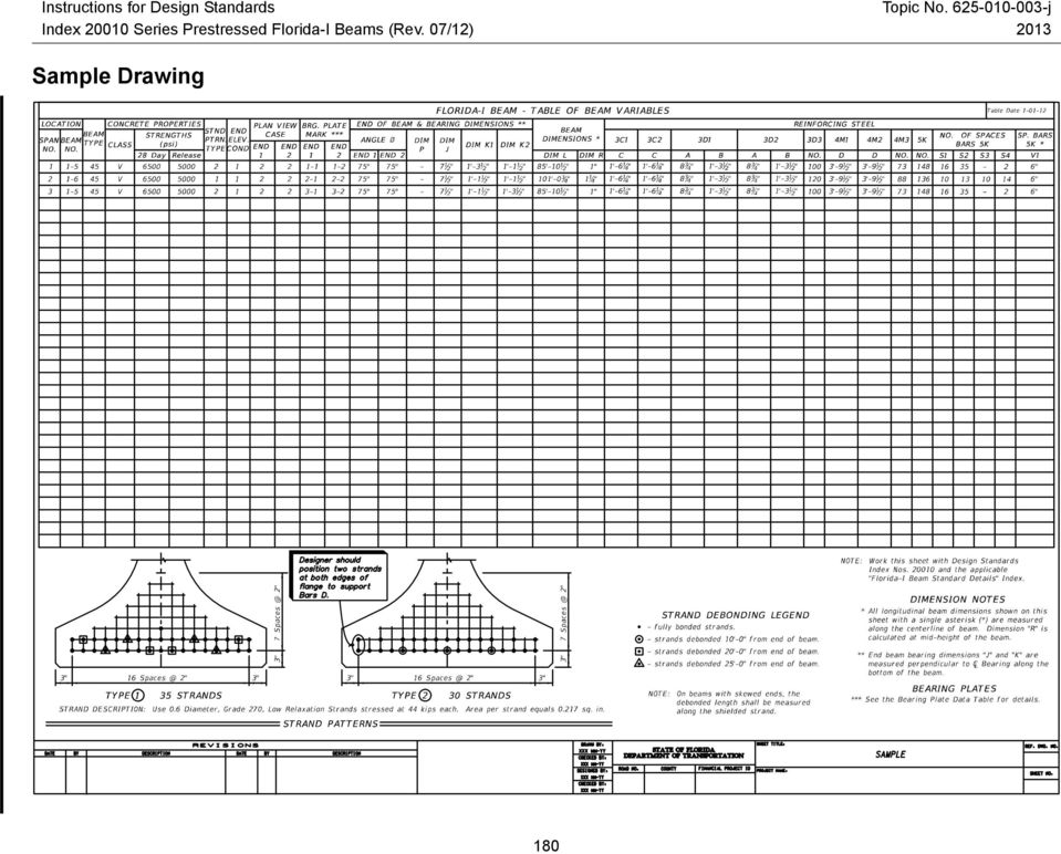
5 Payment Item number Item description Unit Measure AAA Prestressed Beams: Florida-I Beam LF Example Problem The following example shows the data required for completion of a Florida-I Beam Table of Beam Variables. The example assumes a three span bridge with Florida-I 45 Beams designed for the following conditions: Live Load: HL-93 No intermediate Diaphragms Stay-in-Place Metal Forms: Allowance of 20 PSF non-composite dead load over the projected plan area of the forms (this includes the unit weight of metal forms and the concrete required to fill the form flutes). Environment (Superstructure): Moderately Aggressive Bridge Characteristics: Length: 276 ft. Width: 51'-1" (out-to-out) Clear Roadway: 48 ft. Superstructure: Three simple spans of prestressed concrete beams with 8-inch composite deck slab (plus ½" sacrificial deck thickness) Span: 87'-0", 102'-0", 87'-0" Sidewalk: None Horizontal Alignment: Straight Vertical Alignment: 0.00% Grade Skew Angle: 15 degrees (Right) Beam Design: Beam: Florida-I 45 Beam Spacing: 11'-3", 87' Span (5 Beams) 9'-0", 102' Span (6 Beams) Design Span Length: 84'-6" (Spans 1 & 3) 99'-8" (Span 2) 179
.")
6 Sample Drawing 180
7 Design Aids Max Beam Span (ft.) FIB 96" FIB 84" FIB 78" FIB 72" FIB 63" FIB 54" FIB 45" FIB 36" 208 Florida I Beam Estimated Maximum Span Lengths *Moderately Aggressive Environment, FDOT Limits with 8.5 ksi Concrete ' 8' 10' 12' Florida I 96 Beam Florida I 84 Beam Florida I 78 Beam Florida I 72 Beam Florida I 63 Beam Florida I 54 Beam Florida I 45 Beam Florida I 36 Beam *Chart Design Assumptions: interior beam design moderately aggressive corrosive conditions beam concrete strength: 8.5 final 6.0 release deck concrete strength: 4.5 final 6 beams in bridge section 2~32" F Shape barriers applied and distributed evenly over all beams 8 inch composite bridge deck with additional non structural 1/2" sacrificial surface 20 psf S I P form weight applied 1 inch structural build up applied (min. required for 2% cross slope) 0.1 kip/lf applied per beam for additional misc. dead loads including build up HL 93 Live Load applied FDOT Standard splitting/bursting reinforcement used All revised FDOT 2009 SDG criteria regarding splitting, debonding, and stress limits are followed Spans shown are bearing to bearing 0.6~270K Low Lax Strands used Beam Spacing (ft.) 181

8 FIB 96" 208 Florida I Beam Estimated Maximum Span Lengths *Extremely Aggressive Environment, FDOT Limits with 8.5 ksi Concrete 195 Florida I 96 Beam Florida I 84 Beam Florida I 78 Beam Max Beam Span (ft.) FIB 84" FIB 78" FIB 72" FIB 63" FIB 54" FIB 45" FIB 36" ' 8' 10' 12' Florida I 72 Beam Florida I 63 Beam Florida I 54 Beam Florida I 45 Beam Florida I 36 Beam *Chart Design Assumptions: interior beam design extremely aggressive corrosive conditions beam concrete strength: 8.5 final 6.0 release deck concrete strength: 4.5 final 6 beams in bridge section 2~32" F Shape barriers applied and distributed evenly over all beams 8 inch composite bridge deck with additional non structural 1/2" sacrificial surface 20 psf S I P form weight applied 1 inch structural build up applied (min. required for 2% cross slope) 0.1 kip/lf applied per beam for additional misc. dead loads including build up HL 93 Live Load applied FDOT Standard splitting/bursting reinforcement used All revised FDOT 2009 SDG criteria regarding splitting, debonding, and stress limits are followed Spans shown are bearing to bearing 0.6~270K Low Lax Strands used Beam Spacing (ft.) 182

9 FIB-36 SECTION PROPERTIES Area (in. 2 ) Perimeter (in.) Ixx (in. 4 ) 127,545 Iyy (in. 4 ) 81,070 yt (in.) yb (in.) FIB-45 SECTION PROPERTIES Area (in. 2 ) Perimeter (in.) Ixx (in. 4 ) 226,581 Iyy (in. 4 ) 81,327 yt (in.) yb (in.) FIB-54 SECTION PROPERTIES Area (in. 2 ) Perimeter (in.) Ixx (in. 4 ) 359,929 Iyy (in. 4 ) 81,584 yt (in.) yb (in.)
 932.58 Perimeter (in.) 242.57 Ixx (in. 4 ) 359,929 Iyy (in.")
10 FIB-63 SECTION PROPERTIES Area (in. 2 ) Perimeter (in.) Ixx (in. 4 ) 530,313 Iyy (in. 4 ) 81,842 yt (in.) yb (in.) FIB-72 SECTION PROPERTIES Area (in. 2 ) 1, Perimeter (in.) Ixx (in. 4 ) 740,416 Iyy (in. 4 ) 82,099 yt (in.) yb (in.) FIB-78 SECTION PROPERTIES Area (in. 2 ) 1, Perimeter (in.) Ixx (in. 4 ) 903,861 Iyy (in. 4 ) 82,270 yt (in.) yb (in.)
 1,100.58 Perimeter (in.) 290.57 Ixx (in. 4 ) 903,861 Iyy (in.")
11 FIB-84 SECTION PROPERTIES Area (in. 2 ) 1, Perimeter (in.) Ixx (in. 4 ) x 10 6 Iyy (in. 4 ) 82,442 yt (in.) yb (in.) FIB-96 SECTION PROPERTIES Area (in. 2 ) 1, Perimeter (in.) Ixx (in. 4 ) x 10 6 Iyy (in. 4 ) 82,785 yt (in.) yb (in.)
 326.57 Ixx (in. 4 ) 1.515 x 10 6 Iyy (in. 4 ) 82,785 yt (in.) 53.")
Prestressed Concrete I-Beam and TxGirder Haunch Design Guide
 Prestressed Concrete I-Beam and TxGirder Haunch Design Guide Components of the Haunch Camber: Camber is the upward deflection in the beam after release of the prestressing strands due to the eccentricity
Reinforced Concrete Slab Design Using the Empirical Method
 Reinforced Concrete Slab Design Using the Empirical Method BridgeSight Solutions for the AASHTO LRFD Bridge Design Specifications BridgeSight Software TM Creators of effective and reliable solutions for
Detailing of Reinforcment in Concrete Structures
 Chapter 8 Detailing of Reinforcment in Concrete Structures 8.1 Scope Provisions of Sec. 8.1 and 8.2 of Chapter 8 shall apply for detailing of reinforcement in reinforced concrete members, in general. For
APPENDIX H DESIGN CRITERIA FOR NCHRP 12-79 PROJECT NEW BRIDGE DESIGNS
 APPENDIX H DESIGN CRITERIA FOR NCHRP 12-79 PROJECT NEW BRIDGE DESIGNS This appendix summarizes the criteria applied for the design of new hypothetical bridges considered in NCHRP 12-79 s Task 7 parametric
FOUNDATION DESIGN. Instructional Materials Complementing FEMA 451, Design Examples
 FOUNDATION DESIGN Proportioning elements for: Transfer of seismic forces Strength and stiffness Shallow and deep foundations Elastic and plastic analysis Foundation Design 14-1 Load Path and Transfer to
PENNDOT e-notification
 PENNDOT e-notification Bureau of Project Delivery Bridge Design and Technology Division BRADD No. 036 October 18, 2013 Release of BRADD Version 3.2.0.0 The next release of PennDOT's Bridge Automated Design
TABLE OF CONTENTS. Roof Decks 172 B, BA, BV Deck N, NA Deck. Form Decks 174.6 FD,.6 FDV Deck 1.0 FD, 1.0 FDV Deck 1.5 FD Deck 2.0 FD Deck 3.
 Pages identified with the NMBS Logo as shown above, have been produced by NMBS to assist specifiers and consumers in the application of New Millennium Building Systems Deck products. Pages identified with
A transverse strip of the deck is assumed to support the truck axle loads. Shear and fatigue of the reinforcement need not be investigated.
 Design Step 4 Design Step 4.1 DECK SLAB DESIGN In addition to designing the deck for dead and live loads at the strength limit state, the AASHTO-LRFD specifications require checking the deck for vehicular
TECHNICAL SPECIFICATION SERIES 8000 PRECAST CONCRETE
 TECHNICAL SPECIFICATION SERIES 8000 PRECAST CONCRETE TECHNICAL SPECIFICATION PART 8000 - PRECAST CONCRETE TABLE OF CONTENTS Item Number Page 8100 PRECAST CONCRETE CONSTRUCTION - GENERAL 8-3 8101 General
Challenging Skew: Higgins Road Steel I-Girder Bridge over I-90 OTEC 2015 - October 27, 2015 Session 26
 2014 HDR Architecture, 2014 2014 HDR, HDR, Inc., all all rights reserved. Challenging Skew: Higgins Road Steel I-Girder Bridge over I-90 OTEC 2015 - October 27, 2015 Session 26 Brandon Chavel, PhD, P.E.,
FOOTING DESIGN EXAMPLE
 County: Any Design: BRG Date: 10/007 Hwy: Any Ck Dsn: BRG Date: 10/007 FOOTING DESIGN EXAMPLE Design: Based on AASHTO LRFD 007 Specifications, TxDOT LRFD Bridge Design Manual, and TxDOT Project 0-4371
Safe & Sound Bridge Terminology
 Safe & Sound Bridge Terminology Abutment A retaining wall supporting the ends of a bridge, and, in general, retaining or supporting the approach embankment. Approach The part of the bridge that carries
Draft Table of Contents. Building Code Requirements for Structural Concrete and Commentary ACI 318-14
 Draft Table of Contents Building Code Requirements for Structural Concrete and Commentary ACI 318-14 BUILDING CODE REQUIREMENTS FOR STRUCTURAL CONCRETE (ACI 318 14) Chapter 1 General 1.1 Scope of ACI 318
1997 Uniform Administrative Code Amendment for Earthen Material and Straw Bale Structures Tucson/Pima County, Arizona
 for Earthen Material and Straw Bale Structures SECTION 70 - GENERAL "APPENDIX CHAPTER 7 - EARTHEN MATERIAL STRUCTURES 70. Purpose. The purpose of this chapter is to establish minimum standards of safety
Two-Way Post-Tensioned Design
 Page 1 of 9 The following example illustrates the design methods presented in ACI 318-05 and IBC 2003. Unless otherwise noted, all referenced table, figure, and equation numbers are from these books. The
Long-term serviceability of the structure Minimal maintenance requirements Economical construction Improved aesthetics and safety considerations
 Design Step 7.1 INTEGRAL ABUTMENT DESIGN General considerations and common practices Integral abutments are used to eliminate expansion joints at the end of a bridge. They often result in Jointless Bridges
Steel joists and joist girders are
 THE STEEL CONFERENCE Hints on Using Joists Efficiently By Tim Holtermann, S.E., P.E.; Drew Potts, P.E.; Bob Sellers, P.E.; and Walt Worthley, P.E. Proper coordination between structural engineers and joist
Formwork for Concrete
 UNIVERSITY OF WASHINGTON DEPARTMENT OF CONSTRUCTION MANAGEMENT CM 420 TEMPORARY STRUCTURES Winter Quarter 2007 Professor Kamran M. Nemati Formwork for Concrete Horizontal Formwork Design and Formwork Design
Design of reinforced concrete columns. Type of columns. Failure of reinforced concrete columns. Short column. Long column
 Design of reinforced concrete columns Type of columns Failure of reinforced concrete columns Short column Column fails in concrete crushed and bursting. Outward pressure break horizontal ties and bend
Residential Decks. Planning and Development Services Department
 Building Safety Division 8500 Santa Fe Drive Overland Park, KS 66212 (913) 895-6225 Fax (913) 895-5016 Email: [email protected] Planning and Development Services Department Residential Decks
AISI CHEMICAL COMPOSITION LIMITS: Nonresulphurized Carbon Steels
 AISI CHEMICAL COMPOSITION LIMITS: Nonresulphurized Carbon Steels AISI No. 1008 1010 1012 1015 1016 1017 1018 1019 1020 1021 1022 1023 1024 10 1026 1027 1029 10 1035 1036 1037 1038 1039 10 1041 1042 1043
DESIGN OF PRESTRESSED BARRIER CABLE SYSTEMS
 8601 North Black Canyon Highway Suite 103 Phoenix, AZ 8501 For Professionals Engaged in Post-Tensioning Design Issue 14 December 004 DESIGN OF PRESTRESSED BARRIER CABLE SYSTEMS by James D. Rogers 1 1.0
Overhang Bracket Loading. Deck Issues: Design Perspective
 Deck Issues: Design Perspective Overhang Bracket Loading Deck overhangs and screed rails are generally supported on cantilever brackets during the deck pour These brackets produce an overturning couple
US 51 Ohio River Bridge Engineering and Environmental Study
 US 51 Ohio River Bridge Engineering and Environmental Study ITEM NOS. 1-100.00 & 1-1140.00 Prepared by: Michael Baker Jr., Inc. 9750 Ormsby Station Rd Louisville, KY 40223 August 16, 2013 Table of Contents
How To Design A Post Tensioned Deck For A Building
 SAMUEL ÁVILA STRUCTURAL OPTION FACULTY CONSULTANT: THOMAS BOOTHBY UNIVERSITY OF CENTRAL FLORIDA S ACADEMIC VILLAGES ORLANDO, FL THESIS PROPOSAL EXECUTIVE SUMMARY DECEMBER 12, 2005 Introduction: The University
CONTRACT SPECIFICATIONS - SEISMIC ISOLATION BEARINGS
 CONTRACT SPECIFICATIONS - SEISMIC ISOLATION BEARINGS 1.0 DESIGN 1.1 Scope of Work 1.1.1 This work shall consist of furnishing Isolation Bearings and installing Isolation Bearing Assemblies at the locations
Chapter 3 Pre-Installation, Foundations and Piers
 Chapter 3 Pre-Installation, Foundations and Piers 3-1 Pre-Installation Establishes the minimum requirements for the siting, design, materials, access, and installation of manufactured dwellings, accessory
Design of Steel Structures Prof. S.R.Satish Kumar and Prof. A.R.Santha Kumar. Fig. 7.21 some of the trusses that are used in steel bridges
 7.7 Truss bridges Fig. 7.21 some of the trusses that are used in steel bridges Truss Girders, lattice girders or open web girders are efficient and economical structural systems, since the members experience
Residential Deck Safety, Construction, and Repair
 Juneau Permit Center, 4 th Floor Marine View Center, (907)586-0770 This handout is designed to help you build your deck to comply with the 2006 International Residential Building code as modified by the
PART 1 GENERAL 1.1 SECTION INCLUDES
 J-1 Section 09110 Long Form Specification INTERIOR METAL STUD FRAMING This section includes lightweight, usually 0.036 inch (0.9 mm) thick or lighter, non-axial load bearing metal stud framing including
Tension Development and Lap Splice Lengths of Reinforcing Bars under ACI 318-02
 ENGINEERING DATA REPORT NUMBER 51 Tension Development and Lap Splice Lengths of Reinforcing Bars under ACI 318-02 A SERVICE OF THE CONCRETE REINFORCING STEEL INSTITUTE Introduction Section 1.2.1 in the
Quality Control and Quality Assurance Guide
 Quality Control and Quality Assurance Guide Bridge Division, Design Section October 2013 Table of Contents Chapter 1 About this Guide... 3 Chapter 2 Goals and Objectives... 5 Chapter 3 Participants...
PRESTRESSED CONCRETE. Introduction REINFORCED CONCRETE CHAPTER SPRING 2004. Reinforced Concrete Design. Fifth Edition. By Dr. Ibrahim.
 CHAPTER REINFORCED CONCRETE Reinforced Concrete Design A Fundamental Approach - Fifth Edition Fifth Edition PRESTRESSED CONCRETE A. J. Clark School of Engineering Department of Civil and Environmental
3.1 Historical Considerations
 3. Recommended Scope of Bridge improvements 3.1 Historical Considerations In the fall of 2000, an outside consultant, Fraser Design, suggested that the existing 4 th St. Bridge is potentially eligible
Optimum proportions for the design of suspension bridge
 Journal of Civil Engineering (IEB), 34 (1) (26) 1-14 Optimum proportions for the design of suspension bridge Tanvir Manzur and Alamgir Habib Department of Civil Engineering Bangladesh University of Engineering
Section 5A: Guide to Designing with AAC
 Section 5A: Guide to Designing with AAC 5A.1 Introduction... 3 5A.3 Hebel Reinforced AAC Panels... 4 5A.4 Hebel AAC Panel Design Properties... 6 5A.5 Hebel AAC Floor and Roof Panel Spans... 6 5A.6 Deflection...
Chapter 5 Bridge Deck Slabs. Bridge Engineering 1
 Chapter 5 Bridge Deck Slabs Bridge Engineering 1 Basic types of bridge decks In-situ reinforced concrete deck- (most common type) Pre-cast concrete deck (minimize the use of local labor) Open steel grid
FEBRUARY 2014 LRFD BRIDGE DESIGN 4-1
 FEBRUARY 2014 LRFD BRIDGE DESIGN 4-1 4. STRUCTURAL ANALYSIS AND EVALUATION The analysis of bridges and structures is a mixture of science and engineering judgment. In most cases, use simple models with
SLAB DESIGN EXAMPLE. Deck Design (AASHTO LRFD 9.7.1) TYPICAL SECTION. County: Any Hwy: Any Design: BRG Date: 7/2010
 TYPICAL SECTION. County: Any Hwy: Any Design: BRG Date: 7/2010") County: Any Hwy: Any Design: BRG Date: 7/2010 SLAB DESIGN EXAMPLE Design example is in accordance with the AASHTO LRFD Bridge Design Specifications, 5th Ed. (2010) as prescribed by TxDOT Bridge Design
County: Any Hwy: Any Design: BRG Date: 7/2010 SLAB DESIGN EXAMPLE Design example is in accordance with the AASHTO LRFD Bridge Design Specifications, 5th Ed. (2010) as prescribed by TxDOT Bridge Design
REINFORCED CONCRETE. Reinforced Concrete Design. A Fundamental Approach - Fifth Edition. Walls are generally used to provide lateral support for:
 HANDOUT REINFORCED CONCRETE Reinforced Concrete Design A Fundamental Approach - Fifth Edition RETAINING WALLS Fifth Edition A. J. Clark School of Engineering Department of Civil and Environmental Engineering
AASHTOWare Bridge Design and Rating Training. STL8 Single Span Steel 3D Example (BrDR 6.6)
") AASHTOWare Bridge Design and Rating Training STL8 Single Span Steel 3D Example (BrDR 6.6) Last Modified: 4/28/2015 STL8-1 AASHTOWare BrDR 6.5 AASHTOWare Bridge Design and Rating Training STL8 Single Span
AASHTOWare Bridge Design and Rating Training STL8 Single Span Steel 3D Example (BrDR 6.6) Last Modified: 4/28/2015 STL8-1 AASHTOWare BrDR 6.5 AASHTOWare Bridge Design and Rating Training STL8 Single Span
DESIGN OF SLABS. 3) Based on support or boundary condition: Simply supported, Cantilever slab,
 Based on support or boundary condition: Simply supported, Cantilever slab,") DESIGN OF SLABS Dr. G. P. Chandradhara Professor of Civil Engineering S. J. College of Engineering Mysore 1. GENERAL A slab is a flat two dimensional planar structural element having thickness small compared
DESIGN OF SLABS Dr. G. P. Chandradhara Professor of Civil Engineering S. J. College of Engineering Mysore 1. GENERAL A slab is a flat two dimensional planar structural element having thickness small compared
Technical Notes 3B - Brick Masonry Section Properties May 1993
 Technical Notes 3B - Brick Masonry Section Properties May 1993 Abstract: This Technical Notes is a design aid for the Building Code Requirements for Masonry Structures (ACI 530/ASCE 5/TMS 402-92) and Specifications
4.3.5 - Breakaway Walls
 4.3.5 - Breakaway Walls Elevation of a structure on a properly designed foundation reduces the potential for water damage from flooding. When the space below the lowest elevated floor is maintained free
Materials. Estimating Steel. Players. Materials. Shop Drawings. Detailing Process. Standard shapes. Fabricated members, Built-up sections
 Materials Standard shapes W sections, C channels, Structural T, Angles, Pipes, Tubes, Rods and Plates Fabricated members, Built-up sections Adding plates to beam flanges, Stiffeners to beam webs Built
POST AND FRAME STRUCTURES (Pole Barns)
") POST AND FRAME STRUCTURES (Pole Barns) Post and frame structures. The following requirements serve as minimum standards for post and frame structures within all of the following structural limitations:
POST AND FRAME STRUCTURES (Pole Barns) Post and frame structures. The following requirements serve as minimum standards for post and frame structures within all of the following structural limitations:
The minimum reinforcement for the stem wall is the placement of:
 PolySteel creates an ideal insulated stem wall for concrete slabs that can make this part of your project easier and faster, in addition to making your finished project more energy-efficient. Figures 3.20
The following sketches show the plans of the two cases of one-way slabs. The spanning direction in each case is shown by the double headed arrow.
 9.2 One-way Slabs This section covers the following topics. Introduction Analysis and Design 9.2.1 Introduction Slabs are an important structural component where prestressing is applied. With increase
CHAPTER 9 LONG TERM MONITORING AT THE ROUTE 351 BRIDGE
 CHAPTER 9 LONG TERM MONITORING AT THE ROUTE 351 BRIDGE 9.1 INTRODUCTION An important reason that composite piles have not gained wide acceptance in the civil engineering practice is the lack of a long
SEISMIC DESIGN. Various building codes consider the following categories for the analysis and design for earthquake loading:
 SEISMIC DESIGN Various building codes consider the following categories for the analysis and design for earthquake loading: 1. Seismic Performance Category (SPC), varies from A to E, depending on how the
Remote Monitoring of Soil Pressures on Bridge Footings
 More Info at Open Access Database www.ndt.net/?id=18252 Remote Monitoring of Soil Pressures on Bridge Footings Michael DAVIDSON 1, Zhihui ZHU 2, Issam HARIK 3, Charlie SUN 4, Kevin SANDEFUR 5 1 Bridge
Bridge Type Selection
 Bridge Type Selection The major consideration for bridge type selection for bridges on the State Aid system is initial cost. Future maintenance costs, construction time, and location are considered when
IN-SERVICE PERFORMANCE AND BEHAVIOR CHARACTERIZATION OF THE HYBRID COMPOSITE BRIDGE SYSTEM A CASE STUDY
 IN-SERVICE PERFORMANCE AND BEHAVIOR CHARACTERIZATION OF THE HYBRID COMPOSITE BRIDGE SYSTEM A CASE STUDY John M. Civitillo University of Virginia, USA Devin K. Harris University of Virginia, USA Amir Gheitasi
Section A Roof Truss
 Section A Roof Truss Truss Types Wisconsin Truss, Inc. can build a variety of truss types, pictured below are some common examples. Common Bobtail Scissor Mono Studio Dual Slope Cathedral Tray Vault Parallel
BRIDGE DESIGN SPECIFICATIONS APRIL 2000 SECTION 9 - PRESTRESSED CONCRETE
 SECTION 9 - PRESTRESSED CONCRETE Part A General Requirements and Materials 9.1 APPLICATION 9.1.1 General The specifications of this section are intended for design of prestressed concrete bridge members.
ABSTRACT 1. INTRODUCTION 2. DESCRIPTION OF THE SEGMENTAL BEAM
 Ninth LACCEI Latin American and Caribbean Conference (LACCEI 11), Engineering for a Smart Planet, Innovation, Information Technology and Computational Tools for Sustainable Development, August 3-, 11,
The Impact of Market Demands on Residential Post-Tensioned Foundation Design: An Ethical Dilemma
 The Impact of Market Demands on Residential Post-Tensioned Foundation Design: An Ethical Dilemma Bart B. Barrett, B.S., P.E.1 Kerry S. Lee, M.B.A., P.E., M. ASCE2 Erik L. Nelson, Ph.D., P.E., M. ASCE3
Joist. Reinforcement. Draft 12/7/02
 Joist Reinforcement Draft 12/7/02 1 JOIST REINFORCING The purpose of this CSD Design Aid is to provide procedures and suggested details for the reinforcement of open web steel joists. There are three basic
MEMORANDUM. 1509 West Swann Avenue, Suite 225 Tampa, Florida 33606 Phone (813) 258-8818 Fax (813) 258-8525
 258-8818 Fax (813) 258-8525") 1509 West Swann Avenue, Suite 225 Tampa, Florida 33606 Phone (813) 258-8818 Fax (813) 258-8525 To: From: Date: Subject: Mr. Thomas Gibson, City of St. Petersburg Jeffrey D. Malyszek, PE and Deborah C.
1509 West Swann Avenue, Suite 225 Tampa, Florida 33606 Phone (813) 258-8818 Fax (813) 258-8525 To: From: Date: Subject: Mr. Thomas Gibson, City of St. Petersburg Jeffrey D. Malyszek, PE and Deborah C.
Page 1 of 18 28.4.2008 Sven Alexander Last revised 1.3.2010. SB-Produksjon STATICAL CALCULATIONS FOR BCC 250
 Page 1 of 18 CONTENT PART 1 BASIC ASSUMPTIONS PAGE 1.1 General 1. Standards 1.3 Loads 1. Qualities PART ANCHORAGE OF THE UNITS.1 Beam unit equilibrium 3. Beam unit anchorage in front..1 Check of capacity..
Chapter 8. Flexural Analysis of T-Beams
 Chapter 8. Flexural Analysis of T-s 8.1. Reading Assignments Text Chapter 3.7; ACI 318, Section 8.10. 8.2. Occurrence and Configuration of T-s Common construction type.- used in conjunction with either
SECTION 5 ANALYSIS OF CONTINUOUS SPANS DEVELOPED BY THE PTI EDC-130 EDUCATION COMMITTEE LEAD AUTHOR: BRYAN ALLRED
 SECTION 5 ANALYSIS OF CONTINUOUS SPANS DEVELOPED BY THE PTI EDC-130 EDUCATION COMMITTEE LEAD AUTHOR: BRYAN ALLRED NOTE: MOMENT DIAGRAM CONVENTION In PT design, it is preferable to draw moment diagrams
HURRICANE MITIGATION RETROFITS FOR EXISTING SITE-BUILT SINGLE FAMILY RESIDENTIAL STRUCTURES
 HURRICANE MITIGATION RETROFITS FOR EXISTING SITE-BUILT SINGLE FAMILY RESIDENTIAL STRUCTURES 101 Retrofits Required. Pursuant to Section 553.844 553.884, Florida Statutes, strengthening of existing site-built,
Full Depth Precast Concrete Highway Bridge Decks
 NOVEMBER 2007 STRUCTURES AND MATERIALS TEST LABORATORY Full Depth Precast Concrete Highway Bridge Decks BY PROF. M.G. OLIVA PROF. L.C. BANK Prof. J.S. Russell CIVIL ENGINEERING COLLEGE OF ENGINEERING UNIVERSITY
Hunter College school of Social Work Thesis Proposal
 Fall 2009 Hunter College school of Social Work Thesis Proposal To analyze how energy efficiency can be implemented using facade and green roof redesign. It ties structural engineering concepts with existing
High Strain Dynamic Load Testing of Drilled Shafts
 Supplemental Technical Specification for High Strain Dynamic Load Testing of Drilled Shafts SCDOT Designation: SC-M-712 (9/15) September 3, 2015 1.0 GENERAL This work shall consist of performing high-strain
Reinforced Concrete Design Project Five Story Office Building
 Reinforced Concrete Design Project Five Story Office Building Andrew Bartolini December 7, 2012 Designer 1 Partner: Shannon Warchol CE 40270: Reinforced Concrete Design Bartolini 2 Table of Contents Abstract...3
Requirements for Building Application Submission
 THE DEVELOPMENT CONTROL AND PLANNING BOARD P O Box 597 Phone: 869 465-2277 Bladen Commercial Development Fax: 869 465-5842 Basseterre, St. Kitts Email: [email protected] To: Architects, Designers
CONSTRUCTION DETAILS & LOAD DESIGN CHARTS
 Office and Production 126 New Pace Rd., PO Box 279 Newcomerstown, OH 43832 1-800-446-2188, Fax: 740-498-4184 www.buildwithsips.com CONSTRUCTION DETAILS & LOAD DESIGN CHARTS Table of Contents Description
City of Tucson and Pima County Arizona Building Code Appendix Chapter 72 Straw-Bale Structures
 City of Tucson and Pima County Arizona Building Code Appendix Chapter 72 Straw-Bale Structures SECTION 7201 - PURPOSE The purpose of this appendix chapter is to establish minimum prescriptive standards
Diameter. Swift Lift Round Recess Plug. Note: The diameter of the narrow recess plug is the same as the diameter of the round recess plug.
 P-5 The P-5 is hot forged from carbon steel. The formed head provis spherical seating that the Lifting Eye engages, while a disc-shaped foot is embedd in the concrete. Due to its being a forged part, the
SPECIFICATIONS FOR PRECAST MODULAR BLOCK RETAINING WALL SYSTEM (revised 11/5/13)
") Page 1 of 7 STONE STRONG SYSTEMS SPECIFICATIONS FOR PRECAST MODULAR BLOCK RETAINING WALL SYSTEM (revised ) PART 1: GENERAL 1.01 Description A. Work includes furnishing and installing precast modular blocks
Page 1 of 7 STONE STRONG SYSTEMS SPECIFICATIONS FOR PRECAST MODULAR BLOCK RETAINING WALL SYSTEM (revised ) PART 1: GENERAL 1.01 Description A. Work includes furnishing and installing precast modular blocks
Evaluation of Bridge Performance and Rating through Nondestructive
 Evaluation of Bridge Performance and Rating through Nondestructive Load Testing Final Report Prepared by: Andrew Jeffrey, Sergio F. Breña, and Scott A.Civjan University of Massachusetts Amherst Department
EAST LYME HIGH SCHOOL
 Overview: 1971 N 1966 GYM 1966 CLASSROOM WING 1966 AUD. 1971 GYM 1998 1998 POOL EAST LYME HIGH SCHOOL Original 1966 Building: The original East Lyme High School was constructed in 1966 and was composed
Structural Performance of Highway Bridges under Given Foundation Settlements
 ASEE 2014 Zone I Conference, April 3-5, 2014, University of Bridgeport, Bridgeport, CT, USA. Structural Performance of Highway Bridges under Given Foundation Settlements Zhan Su*; Qian Wang, PhD, PE, Assistant
REPAIR AND STRENGTHENING OF HISTORICAL CONCRETE BRIDGE OVER VENTA RIVER IN LATVIA
 1 REPAIR AND STRENGTHENING OF HISTORICAL CONCRETE BRIDGE OVER VENTA RIVER IN LATVIA Verners Straupe, M.sc.eng., Rudolfs Gruberts, dipl. eng. JS Celuprojekts, Murjanu St. 7a, Riga, LV 1024, Latvia e-mail:
TXDOT ENGINEERING SOFTWARE SUPPORT INFORMATION. Prestressed Concrete Girder SUPERstructure Design and Analysis Program (PGSuper TM )
") Last Update: June 21, 2016 TXDOT ENGINEERING SOFTWARE SUPPORT INFORMATION Prestressed Concrete Girder SUPERstructure Design and Analysis Program (PGSuper TM ) This document provides end-user support information
Last Update: June 21, 2016 TXDOT ENGINEERING SOFTWARE SUPPORT INFORMATION Prestressed Concrete Girder SUPERstructure Design and Analysis Program (PGSuper TM ) This document provides end-user support information
4B-2. 2. The stiffness of the floor and roof diaphragms. 3. The relative flexural and shear stiffness of the shear walls and of connections.
 Shear Walls Buildings that use shear walls as the lateral force-resisting system can be designed to provide a safe, serviceable, and economical solution for wind and earthquake resistance. Shear walls
Introduction...COMB-2 Design Considerations and Examples...COMB-3
 SECTION DIRECTORY General Information Introduction...COMB-2 Design Considerations and Examples...COMB-3 Combination Assembly Recommendations and Limitations Composite Configurations...COMB-4 Typical Sealant
June 2007 CHAPTER 7 - CULVERTS 7.0 CHAPTER 7 - CULVERTS 7.1 GENERAL
 7.0 7.1 GENERAL For the purpose of this manual, culverts are defined as structures that are completely surrounded by soil and located below the surface of the roadway parallel to the general direction
PCI BIG BEAM COMPETITION
 PCI BIG BEAM COMPETITION Official Rules for the PCI Engineering Design Competition Academic Year 2015-16 PROGRAM The PCI Student Education Committee is inviting entries from students to participate in
Chapter. Earthquake Damage: Types, Process, Categories
 3 Chapter Earthquake Damage: Types, Process, Categories Earthquakes leave behind a trail of damage and destruction. People s lives are affected by the loss of loved ones, destruction of property, economic
NCMA TEK CONCRETE MASONRY FOUNDATION WALL DETAILS. TEK 5-3A Details (2003)
") NCMA TEK National Concrete Masonry Association an information series from the national authority on concrete masonry technology CONCRETE MASONRY FOUNDATION WALL DETAILS TEK 5-3A Details (2003) Keywords:
NCMA TEK National Concrete Masonry Association an information series from the national authority on concrete masonry technology CONCRETE MASONRY FOUNDATION WALL DETAILS TEK 5-3A Details (2003) Keywords:
[TECHNICAL REPORT I:]
![[TECHNICAL REPORT I:]](/thumbs/26/8259375.jpg "[TECHNICAL REPORT I:]") [Helios Plaza] Houston, Texas Structural Option Adviser: Dr. Linda Hanagan [TECHNICAL REPORT I:] Structural Concepts & Existing Conditions Table of Contents Executive Summary... 2 Introduction... 3 Structural
[Helios Plaza] Houston, Texas Structural Option Adviser: Dr. Linda Hanagan [TECHNICAL REPORT I:] Structural Concepts & Existing Conditions Table of Contents Executive Summary... 2 Introduction... 3 Structural
SECTION 3 DESIGN OF POST TENSIONED COMPONENTS FOR FLEXURE
 SECTION 3 DESIGN OF POST TENSIONED COMPONENTS FOR FLEXURE DEVELOPED BY THE PTI EDC-130 EDUCATION COMMITTEE LEAD AUTHOR: TREY HAMILTON, UNIVERSITY OF FLORIDA NOTE: MOMENT DIAGRAM CONVENTION In PT design,
SUPPLEMENTAL TECHNICAL SPECIFICATIONS BI-DIRECTIONAL STATIC LOAD TESTING OF DRILLED SHAFTS
 July 14, 2015 1.0 GENERAL BI-DIRECTIONAL STATIC LOAD TESTING OF DRILLED SHAFTS This work shall consist of furnishing all materials, equipment, labor, and incidentals necessary for conducting bi-directional
Type of Force 1 Axial (tension / compression) Shear. 3 Bending 4 Torsion 5 Images 6 Symbol (+ -)
 Shear. 3 Bending 4 Torsion 5 Images 6 Symbol (+ -)") Cause: external force P Force vs. Stress Effect: internal stress f 05 Force vs. Stress Copyright G G Schierle, 2001-05 press Esc to end, for next, for previous slide 1 Type of Force 1 Axial (tension /
Cause: external force P Force vs. Stress Effect: internal stress f 05 Force vs. Stress Copyright G G Schierle, 2001-05 press Esc to end, for next, for previous slide 1 Type of Force 1 Axial (tension /
Value Engineering vs. Alternate Designs in Bridge Bidding
 Value Engineering vs. Alternate Designs in Bridge Bidding Compares the advantages and disadvantages of alternate designs and value engineering in bidding of bridges as experienced in the State of Florida.
Bracing Webs in Trusses that have Dissimilar Configurations
 Bracing Webs in Trusses that have Dissimilar Configurations Released April 25, 2006 Issue: Truss Design Drawings (TDD) that are prepared in accordance with ANSI/TPI 1, National Design Standard for Metal
SECTION 15076 CEMENT-MORTAR LINED AND COATED STEEL PIPE
 SECTION 15076 CEMENT-MORTAR LINED AND COATED (CML&C) STEEL PIPE PART 1 GENERAL 1.01 DESCRIPTION This section designates the requirements for steel pipe fabrication, test in shop, installation of steel
Steel and composite bridges in Germany State of the Art
 Steel and composite bridges in Germany State of the Art Univ.-Prof. Dr.-Ing. G. Hanswille Institute for Steel and Composite Structures University of Wuppertal Germany Univ.-Prof. em. Dr.-Ing. Dr. h.c.
SUPER-T. Standardisation and Detailing for. Bridge Girders. Structural Concrete Industries
 Standardisation and Detailing for SUPER-T Bridge Girders Towards National Standardisation of Super-T Bridge Girders Page 1 of 16 Authors NAME: EMPLOYER: POSITION: QUALIFICATIONS: SHORT RESUME: Wolfgang
National Council of Examiners for Engineering and Surveying. Principles and Practice of Engineering Structural Examination
 Structural Effective Beginning with the April 2011 The structural engineering exam is a breadth and exam examination offered in two components on successive days. The 8-hour Vertical Forces (Gravity/Other)
SLAB DESIGN. Introduction ACI318 Code provides two design procedures for slab systems:
 Reading Assignment SLAB DESIGN Chapter 9 of Text and, Chapter 13 of ACI318-02 Introduction ACI318 Code provides two design procedures for slab systems: 13.6.1 Direct Design Method (DDM) For slab systems
Chapter 12 LOADS AND LOAD FACTORS NDOT STRUCTURES MANUAL
 Chapter 12 LOADS AND LOAD FACTORS NDOT STRUCTURES MANUAL September 2008 Table of Contents Section Page 12.1 GENERAL... 12-1 12.1.1 Load Definitions... 12-1 12.1.1.1 Permanent Loads... 12-1 12.1.1.2 Transient
FINAL FAILURE INVESTIGATION WESTCHESTER NORTH LAGOON BRIDGE. Anchorage, Alaska
 FINAL FAILURE INVESTIGATION WESTCHESTER NORTH LAGOON BRIDGE Anchorage, Alaska August 2014 Prepared for: Municipality of Anchorage Project Management and Engineering P.O. Box 196650 Anchorage, Alaska 99519-6650
STANDARD REQUIREMENTS FOR BONDING OR MECHANICAL ATTACHMENT OF INSULATION PANELS AND MECHANICAL ATTACHMENT OF ANCHOR AND/OR BASE SHEETS TO SUBSTRATES
 ROOFING APPLICATION STANDARD (RAS) No. 117 STANDARD REQUIREMENTS FOR BONDING OR MECHANICAL ATTACHMENT OF INSULATION PANELS AND MECHANICAL ATTACHMENT OF ANCHOR AND/OR BASE SHEETS TO SUBSTRATES Scope 1.1.
STRUCTURAL CONCEPT FOR LIGHT GAUGE STEEL FRAME SYSTEM
 Chapter 9 STRUCTURAL CONCEPT FOR LIGHT GAUGE STEEL FRAME SYSTEM 9.1 BACKGROUND Steel is widely used in the construction of multi-storey buildings. However, steel construction is seldom used and is traditionally
PTS HELICAL PIERS INSTALLATION SPECIFICATIONS NOTICE
 FORM A PTS HELICAL PIERS INSTALLATION SPECIFICATIONS NOTICE The following suggested specifications are written as a guide to assist the specifier in writing his own specifications. Specific circumstances