DESIGN OF SLABS. Department of Structures and Materials Engineering Faculty of Civil and Environmental Engineering University Tun Hussein Onn Malaysia
|
|
|
- Derrick Newman
- 7 years ago
- Views:
Transcription
1 DESIGN OF SLABS Department of Structures and Materials Engineering Faculty of Civil and Environmental Engineering University Tun Hussein Onn Malaysia

2 Introduction Types of Slab Slabs are plate elements forming floors and roofs in buildings which normally carry uniformly distributed loads. Slabs may be simply supported or continuous over one or more supports and are classified according to the method of support as follows: Spanning one way between beams or walls Spanning two ways between the support beams or walls Flat slabs carried on columns and edge beams or walls with no interior beams Slabs may be solid of uniform thickness or ribbed with ribs running in one or two directions. Slabs with varying depth are generally not used.

3 Introduction Slab are horizontal plate elements forming floor and roof in building and normally carry lateral actions. Slabs may be solid of uniform thickness or ribbed with ribs running in one or two direction. b L = Span h B = width H = depth or thickness L

4 Introduction Slabs may be simply supported or continuous over one or more supports and are classified according to the method of support: Spanning one way between beams or walls Spanning two ways between the support beams or walls Flat slabs carried on columns and edge beams or walls with no interior beams Type of slab: One-way solid slab: Slabs of uniform thickness bending and reinforced in one direction. Suitable only for relatively short spans. Two-way solid slab: Slabs of uniform thickness bending and reinforced in two directions. Economical for medium spans with intermediate to heavy loads.

5 Introduction Ribbed slabs: Slab cast integrally with a series of closely spaced joist which in turn are supported by a set of beams. Designed as a series of parallel T-beams and economical for medium spans with light to medium live loads. Waffle slabs: A two-way slab reinforced by ribs in two-dimensions. Able to carry heavier loads and span longer than ribbed slabs. Flab slabs: Slabs of uniform thickness bending and reinforced in two directions and supported directly by columns without beams. Flat slabs with drop panel: Flat slab thickness at its column supports with column capitals or drop panels to increase strength and moment-resisting capacity. Suitable for heavily loaded span.

6 Introduction Ribbed slab One-way slab Waffle slab One-way slab two-way slab

7 Introduction Flat slab Flat slab with drop panel two-way slab

8 Introduction This is a band beam and slab construction, where shallow band beams are used to minimise the depth One-way slab

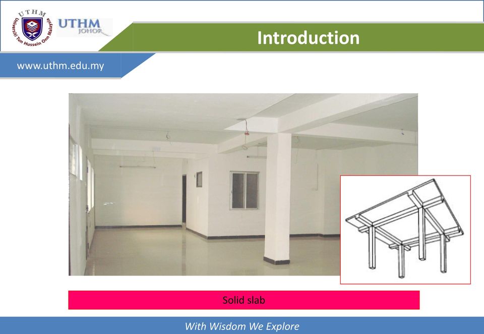
9 Introduction Solid slab
10 Introduction Flat slab without drop panel

11 Introduction Drop panel Flat slab with drop panel

12 Introduction Waffle slab

13 Introduction One-way Ribbed slab

14 Introduction Precast concrete slab

15 Analysis of Slab Slabs may be analysed using the following methods. Elastic analysis covers three techniques: (a) idealization into strips or beams spanning one way or a grid with the strips spanning two ways (b) elastic plate analysis (c) finite element analysis the best method for irregularly shaped slabs or slabs with non-uniform loads For the method of design coefficients use is made of the moment and shear coefficients given in the code, which have been obtained from yield line analysis. The yield line and Hillerborg strip methods are limit design or collapse loads methods.

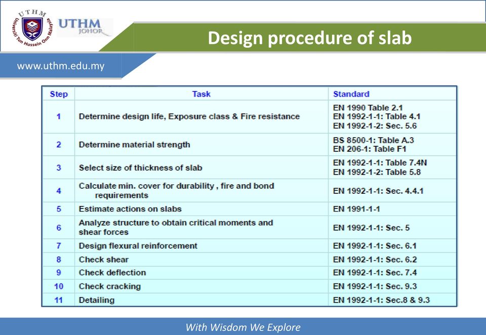
16 Design Procedure RC slab behave primarily as flexural members with the design similar to that for beams. In general, the design of slab become more simpler because compression reinforcement are often not required and the shear stress are usually low except when there are heavy concentrated load. A design procedure for carrying out detail design of slab may be list out as follows;


17 Design procedure of slab
18 v Slab Thickness The selection of slab thickness from structural viewpoint is often dictated by deflection control criteria. In practice, the overall depths of slabs are often fixed in relation to their spans. Span to overall depth ratios of 20 to 30 are generally found to be economical in the case of simply supported and continuous slabs. h L 20 L 30 Beside of that, slab thickness also control by fire resistance as state in EC2-1-2 (Table 5.8).

19 Slab Thickness


20 Design of Flexural Reinforcement
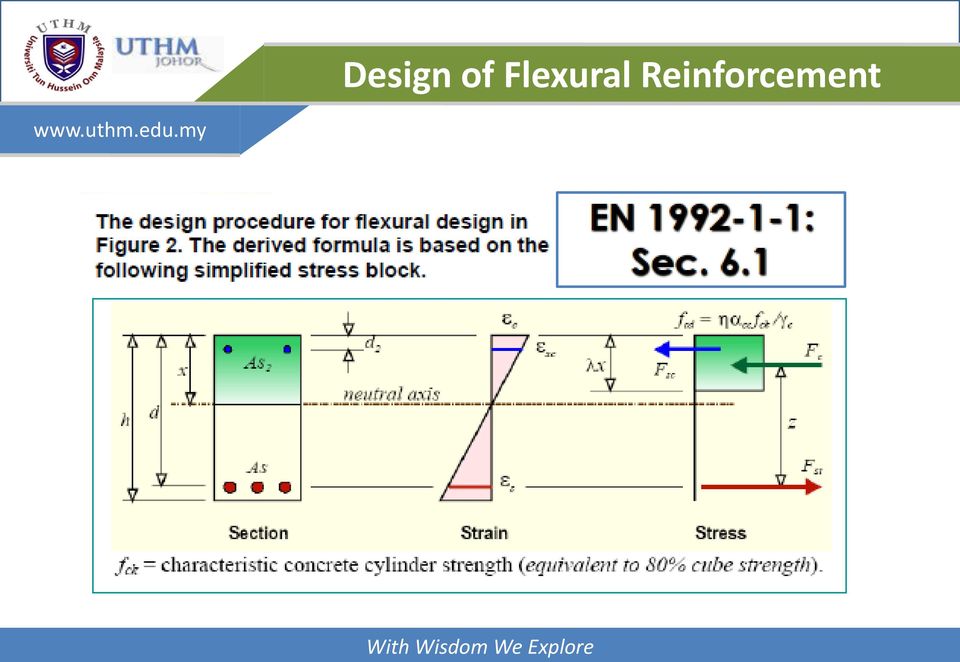
21 Design of Flexural Reinforcement The calculations for flexural reinforcement follow a similar procedure to that use in beam design. 1) Calculate 2) If K K bal (= 0.167), compression reinforcement is not required, and
22 Shear Shear stress in slabs subjected to uniformly distributed loads are generally small. It is not usual for a slab to provide shear reinforcement. It is necessary to ensure that design ultimate shear force, V ed is less than shear strength of the unreinforced section, V Rd,c. V 1/3 Rd ck ], c [0.12k(100 1 f ) bwd [0.035k fck ] bwd 3/ 2 1/ 2 1/ 2 k [1 (200/ d) ] 2. 0 d in mm 1 ( As1 / bwd) 0.02 A s1 = the area of tensile reinforcement that extends (l bd + d) beyond the section considered. b w = the smallest width of the section in tensile area (mm)
23 Deflection Excessive deflection of slabs will cause damage to the ceiling, floor finishes or other architectural finishes. To avoid this, limit are set on the span-depth ratio. These limit are similarly to limit for beams. As a slab is usually a slender member, the restrictions on the span-depth ratio become more important and this can often control the depth of slab required.
24 Cracking To resist cracking of the concrete slabs, EC2 (Sec ) specify details such as minimum area of reinforcement required in a section and limits to the maximum and minimum spacing of bar. The minimum area of principal reinforcement is A s,min = 0.26f ctm b t d/f yk but not less than b t d, where b t is the mean width of the tension zone. The minimum area of secondary reinforcement is 20% A s,min. In areas near support, transverse reinforcement is not necessary where there is no transverse bending moment. The spacing of principal reinforcement bars should not exceed three times the overall depth of slab (3h) or 400 mm whichever is the lesser. For secondary reinforcement the spacing should not exceed 3.5h or 450 mm whichever the lesser. These rules apply for slabs not exceeding 200 mm thick.
25 Design of One-Way Slab Slab are considered as one-way if the main reinforcement is designed only in one direction. This condition occur if the slab supported by two side of beam or walls. If slab supported by four side of beams or walls, the slab is considered oneway if ratio of long span (Ly) to short span (Lx) greater than 2. Otherwise, the slab is state as two-way slab.
26 Design of One-Way Slab One-way slabs carrying predominantly uniform load are designed on the assumption that they consist of a series of rectangular beams 1 m wide spanning between supporting beams or walls. The sections through a simply supported slab and a continuous slab are shown in figure below.
27 One-way simply supported slab Analysis and design of the slab similar to design of simply supported beam as indicate in the previous chapter. For 1m slab width, 2 Moment, wl Shear Force, wl M V max max 8 2 One-way Continuous slab Design of One-Way Slab For continuous slab, moment and shear force can be obtained from Table 3.12: BS 8110 if the following conditions applied. 1.35Gk + 1.5Qk
28 Design of One-Way Slab The area of each bay, i.e. the building width column spacing, exceeds 30 m 2. The ratio of characteristic imposed load to characteristic dead load does not exceed The characteristic imposed load does not exceed 5 kn/m 2 excluding partitions. If the above conditions are not satisfied, the slab can be analyzed using elastic analysis as performed for continuous beams.
29 Design of Two-Way Slab The main reinforcement for two-way slab are designed in two directions which are x-direction and y-direction. This condition occur when the slab are supported at four side of the beams or walls and the ratio of long span to short span is equal or less than 2. Bending moment and shear force of two-way slab are depend on L y /L x ratio and support condition either simply supported or end restraint.
30 Design of Two-Way Slab Two-Way Simply Supported Slab If the slab consist of one panel and end support are not restrained, (the slab and beam are not connected monolithically) the slab are classify as two-way simply supported slab. When simply-supported slabs do not have adequate provision to resist torsion at the corners, and to prevent the corners from lifting, the maximum moments per unit width are given by the following equations: Moment at short span; Moment at long span; M M sx sy Where; α sx, α sy = moment coefficient from Table 3.13 (BS8110:1:1997). n = design load (kn/m 2 ) L x = short span (m) n. L n. L 2. sx x 2 sy. x

31 Design of Two-Way Slab
32 Design of Two-Way Slab Two-Way Restrained Slab If the slabs consist more than one panel or corner of the slab are prevent against lifting it is define as two-way restrained slab. This condition occur when the slabs are connected monolithically with support. The design bending moment of two-way restrained slab can be calculated as follows; Moment at short span, 2 Moment at long span, M. n. L sx sx x M sy n. L sy. x Where; β sx, β sy = moment coefficient from Table 3.14 (BS8110:1:1997) n = design load (kn/m 2 ) L x = short span (m) 2
33 Design of Two-Way Slab
34 Design of Two-Way Slab Bending moment of two-way restrained slab depends on the ratio of L y /L x and continuity of slab edges. There are 9 cases of slab edge continuity that may be exist as shown in figure below. The design shear force of two-way restrained slab can be calculated as follows; Shear force at short span, Shear force at long span, Where; β vx, β vy = moment coefficient from Table 3.15 (BS8110:1:1997) n = design load (kn/m 2 ) L x = short span (m) V. n. L sx vx V. n. L sy vy x x
35 Design of Two-Way Slab Cases of Two- Way restrained slab

36 Design of Two-Way Slab Case 1 Case 2 Case 3 Case 4 Case 5 Case 6 Case 7 Case 8 Case 9
37 Design of Two-Way Slab Case 1 Case 2 Case 3 Case 4 Case 5 Case 6 Case 7 Case 8 Case 9
DESIGN OF SLABS. 3) Based on support or boundary condition: Simply supported, Cantilever slab,
 Based on support or boundary condition: Simply supported, Cantilever slab,") DESIGN OF SLABS Dr. G. P. Chandradhara Professor of Civil Engineering S. J. College of Engineering Mysore 1. GENERAL A slab is a flat two dimensional planar structural element having thickness small compared
DESIGN OF SLABS Dr. G. P. Chandradhara Professor of Civil Engineering S. J. College of Engineering Mysore 1. GENERAL A slab is a flat two dimensional planar structural element having thickness small compared
SLAB DESIGN. Introduction ACI318 Code provides two design procedures for slab systems:
 Reading Assignment SLAB DESIGN Chapter 9 of Text and, Chapter 13 of ACI318-02 Introduction ACI318 Code provides two design procedures for slab systems: 13.6.1 Direct Design Method (DDM) For slab systems
The following sketches show the plans of the two cases of one-way slabs. The spanning direction in each case is shown by the double headed arrow.
 9.2 One-way Slabs This section covers the following topics. Introduction Analysis and Design 9.2.1 Introduction Slabs are an important structural component where prestressing is applied. With increase
9.3 Two-way Slabs (Part I)
") 9.3 Two-way Slabs (Part I) This section covers the following topics. Introduction Analysis and Design Features in Modeling and Analysis Distribution of Moments to Strips 9.3.1 Introduction The slabs are
9.3 Two-way Slabs (Part I) This section covers the following topics. Introduction Analysis and Design Features in Modeling and Analysis Distribution of Moments to Strips 9.3.1 Introduction The slabs are
16. Beam-and-Slab Design
 ENDP311 Structural Concrete Design 16. Beam-and-Slab Design Beam-and-Slab System How does the slab work? L- beams and T- beams Holding beam and slab together University of Western Australia School of Civil
Design Of Reinforced Concrete Structures ii Two-Way Slabs
 1. Inroduction When the ratio (L/S) is less than 2.0, slab is called two-way slab, as shown in the fig. below. Bending will take place in the two directions in a dish-like form. Accordingly, main reinforcement
Draft Table of Contents. Building Code Requirements for Structural Concrete and Commentary ACI 318-14
 Draft Table of Contents Building Code Requirements for Structural Concrete and Commentary ACI 318-14 BUILDING CODE REQUIREMENTS FOR STRUCTURAL CONCRETE (ACI 318 14) Chapter 1 General 1.1 Scope of ACI 318
Chapter 8. Flexural Analysis of T-Beams
 Chapter 8. Flexural Analysis of T-s 8.1. Reading Assignments Text Chapter 3.7; ACI 318, Section 8.10. 8.2. Occurrence and Configuration of T-s Common construction type.- used in conjunction with either
HOW TO DESIGN CONCRETE STRUCTURES Foundations
 HOW TO DESIGN CONCRETE STRUCTURES Foundations Instructions for the Members of BIBM, CEMBUREAU, EFCA and ERMCO: It is the responsibility of the Members (national associations) of BIBM, CEMBUREAU, EFCA and
Floor structures Building constructure 2 REINFORCED CONCRETE FLOOR STRUCTURES
 REINFORCED CONCRETE FLOOR STRUCTURES Structure of RC floors joist structures Floor structures Building constructure 2 slab structures Classification of RC floor structures Floor structures Building constructure
Formwork for Concrete
 UNIVERSITY OF WASHINGTON DEPARTMENT OF CONSTRUCTION MANAGEMENT CM 420 TEMPORARY STRUCTURES Winter Quarter 2007 Professor Kamran M. Nemati Formwork for Concrete Horizontal Formwork Design and Formwork Design
Concrete Design to Eurocode 2
 Concrete Design to Eurocode 2 Jenny Burridge MA CEng MICE MIStructE Head of Structural Engineering Introduction to the Eurocodes Eurocode Eurocode 1 Eurocode 2 Materials Cover Flexure Shear Deflection
SECTION 5 ANALYSIS OF CONTINUOUS SPANS DEVELOPED BY THE PTI EDC-130 EDUCATION COMMITTEE LEAD AUTHOR: BRYAN ALLRED
 SECTION 5 ANALYSIS OF CONTINUOUS SPANS DEVELOPED BY THE PTI EDC-130 EDUCATION COMMITTEE LEAD AUTHOR: BRYAN ALLRED NOTE: MOMENT DIAGRAM CONVENTION In PT design, it is preferable to draw moment diagrams
Reinforced Concrete Design Project Five Story Office Building
 Reinforced Concrete Design Project Five Story Office Building Andrew Bartolini December 7, 2012 Designer 1 Partner: Shannon Warchol CE 40270: Reinforced Concrete Design Bartolini 2 Table of Contents Abstract...3
Technical Notes 3B - Brick Masonry Section Properties May 1993
 Technical Notes 3B - Brick Masonry Section Properties May 1993 Abstract: This Technical Notes is a design aid for the Building Code Requirements for Masonry Structures (ACI 530/ASCE 5/TMS 402-92) and Specifications
FUTURE SLAB. PENETRATIONS and. DEMOLITION of POST-TENSIONED FLOORS
 FUTURE SLAB PENETRATIONS and DEMOLITION of POST-TENSIONED FLOORS 1.0 INTRODUCTION Post-tensioned floor slabs in Australia and South East Asia are now universally regarded as the most cost effective form
Optimum proportions for the design of suspension bridge
 Journal of Civil Engineering (IEB), 34 (1) (26) 1-14 Optimum proportions for the design of suspension bridge Tanvir Manzur and Alamgir Habib Department of Civil Engineering Bangladesh University of Engineering
MECHANICS OF SOLIDS - BEAMS TUTORIAL 1 STRESSES IN BEAMS DUE TO BENDING. On completion of this tutorial you should be able to do the following.
 MECHANICS OF SOLIDS - BEAMS TUTOIAL 1 STESSES IN BEAMS DUE TO BENDING This is the first tutorial on bending of beams designed for anyone wishing to study it at a fairly advanced level. You should judge
SEISMIC DESIGN. Various building codes consider the following categories for the analysis and design for earthquake loading:
 SEISMIC DESIGN Various building codes consider the following categories for the analysis and design for earthquake loading: 1. Seismic Performance Category (SPC), varies from A to E, depending on how the
INTRODUCTION TO BEAMS
 CHAPTER Structural Steel Design LRFD Method INTRODUCTION TO BEAMS Third Edition A. J. Clark School of Engineering Department of Civil and Environmental Engineering Part II Structural Steel Design and Analysis
Design of Steel Structures Prof. S.R.Satish Kumar and Prof. A.R.Santha Kumar
 Problem 1 Design a hand operated overhead crane, which is provided in a shed, whose details are: Capacity of crane = 50 kn Longitudinal spacing of column = 6m Center to center distance of gantry girder
Design of reinforced concrete columns. Type of columns. Failure of reinforced concrete columns. Short column. Long column
 Design of reinforced concrete columns Type of columns Failure of reinforced concrete columns Short column Column fails in concrete crushed and bursting. Outward pressure break horizontal ties and bend
1997 Uniform Administrative Code Amendment for Earthen Material and Straw Bale Structures Tucson/Pima County, Arizona
 for Earthen Material and Straw Bale Structures SECTION 70 - GENERAL "APPENDIX CHAPTER 7 - EARTHEN MATERIAL STRUCTURES 70. Purpose. The purpose of this chapter is to establish minimum standards of safety
Module 5 (Lectures 17 to 19) MAT FOUNDATIONS
 MAT FOUNDATIONS") Module 5 (Lectures 17 to 19) MAT FOUNDATIONS Topics 17.1 INTRODUCTION Rectangular Combined Footing: Trapezoidal Combined Footings: Cantilever Footing: Mat foundation: 17.2 COMMON TYPES OF MAT FOUNDATIONS
Module 5 (Lectures 17 to 19) MAT FOUNDATIONS Topics 17.1 INTRODUCTION Rectangular Combined Footing: Trapezoidal Combined Footings: Cantilever Footing: Mat foundation: 17.2 COMMON TYPES OF MAT FOUNDATIONS
FOUNDATION DESIGN. Instructional Materials Complementing FEMA 451, Design Examples
 FOUNDATION DESIGN Proportioning elements for: Transfer of seismic forces Strength and stiffness Shallow and deep foundations Elastic and plastic analysis Foundation Design 14-1 Load Path and Transfer to
Fire and Concrete Structures
 Fire and Concrete Structures Authors: David N. Bilow, P.E., S.E., Director, Engineered Structures, Portland Cement Association 5420 Old Orchard Road, Skokie, IL 60077,Phone 847-972-9064, email: dbilow@cement.org
Chapter 2 Basis of design and materials
 Chapter 2 Basis of design and materials 2.1 Structural action It is necessary to start a design by deciding on the type and layout of structure to be used. Tentative sizes must be allocated to each structural
Design of prestressed Concrete flat slabs
 Report No. 2 Design of prestressed Concrete flat slabs Joint Structural Division of the South African Institution of Civil Engineering and the Institution of Structural Engineers ISBN 0-620 - 17667-9 The
Aluminium systems profile selection
 Aluminium systems profile selection The purpose of this document is to summarise the way that aluminium profile selection should be made, based on the strength requirements for each application. Curtain
Code of Practice for Structural Use of Concrete 2013
 Code of Practice for Structural Use of Concrete 2013 The Government of the Hong Kong Special Administrative Region Published: February 2013 Prepared by: Buildings Department 12/F-18/F Pioneer Centre 750
Chapter 5 Bridge Deck Slabs. Bridge Engineering 1
 Chapter 5 Bridge Deck Slabs Bridge Engineering 1 Basic types of bridge decks In-situ reinforced concrete deck- (most common type) Pre-cast concrete deck (minimize the use of local labor) Open steel grid
REINFORCED CONCRETE STRUCTURE DESIGN ASSISTANT TOOL FOR BEGINNERS. Kang-Kyu Choi
 REINFORCED CONCRETE STRUCTURE DESIGN ASSISTANT TOOL FOR BEGINNERS by Kang-Kyu Choi A Thesis Presented to the FACULTY OF THE SCHOOL OF ARCHITECTURE UNIVERSITY OF SOUTHERN CALIFORNIA In Partial Fulfillment
Design and Construction of Cantilevered Reinforced Concrete Structures
 Buildings Department Practice Note for Authorized Persons, Registered Structural Engineers and Registered Geotechnical Engineers APP-68 Design and Construction of Cantilevered Reinforced Concrete Structures
Page 1 of 18 28.4.2008 Sven Alexander Last revised 1.3.2010. SB-Produksjon STATICAL CALCULATIONS FOR BCC 250
 Page 1 of 18 CONTENT PART 1 BASIC ASSUMPTIONS PAGE 1.1 General 1. Standards 1.3 Loads 1. Qualities PART ANCHORAGE OF THE UNITS.1 Beam unit equilibrium 3. Beam unit anchorage in front..1 Check of capacity..
Design of Steel Structures Prof. S.R.Satish Kumar and Prof. A.R.Santha Kumar. Fig. 7.21 some of the trusses that are used in steel bridges
 7.7 Truss bridges Fig. 7.21 some of the trusses that are used in steel bridges Truss Girders, lattice girders or open web girders are efficient and economical structural systems, since the members experience
Design guide. Part 1: Structural Design
 Design guide Part 1: Structural Design Design guide Part 1: Structural Design Advantages: Fast Economical Strong Insulating Environmentally friendly Versatile Modernist house supplied by SIPBuild Vernacular
Structural Analysis. EUROCODE 2 Background and Applications
 Dissemination of information for training Brussels, 20-21 October 2011 1 Prof. Dr.-Ing. Manfred Curbach TU Dresden, Institute for Concrete Structures M.Sc. Martin Just TU Dresden, Institute for Concrete
Optimising plate girder design
 Optimising plate girder design NSCC29 R. Abspoel 1 1 Division of structural engineering, Delft University of Technology, Delft, The Netherlands ABSTRACT: In the design of steel plate girders a high degree
Technical Assignment 2 TABLE OF CONTENTS
 2 TABLE OF CONTENTS Executive Summary...3 Introduction..5 Gravity Loads......6 Design Codes......7 Materials..8 Existing Structural System.. 10 Existing Floor System 15 Alternate Floor Framing Systems...17
Numerical modelling of shear connection between concrete slab and sheeting deck
 7th fib International PhD Symposium in Civil Engineering 2008 September 10-13, Universität Stuttgart, Germany Numerical modelling of shear connection between concrete slab and sheeting deck Noémi Seres
Chapter - 3 Design of Rectangular Beams and One-way Slabs
 Rectangular Beams and One-way Slabs Page 1 of 9 Chapter - 3 Design of Rectangular Beams and One-way Slabs 12 h A 12 strip in a simply supported one-way slab h b=12 L Rectangular Beams and One-way Slabs
RC Detailing to Eurocode 2
 RC Detailing to Eurocode 2 Jenny Burridge MA CEng MICE MIStructE Head of Structural Engineering Structural Eurocodes BS EN 1990 (EC0): BS EN 1991 (EC1): Basis of structural design Actions on Structures
SECTION 3 DESIGN OF POST TENSIONED COMPONENTS FOR FLEXURE
 SECTION 3 DESIGN OF POST TENSIONED COMPONENTS FOR FLEXURE DEVELOPED BY THE PTI EDC-130 EDUCATION COMMITTEE LEAD AUTHOR: TREY HAMILTON, UNIVERSITY OF FLORIDA NOTE: MOMENT DIAGRAM CONVENTION In PT design,
Guidelines for the Design of Post-Tensioned Floors
 Guidelines for the Design of Post-Tensioned Floors BY BIJAN O. AALAMI AND JENNIFER D. JURGENS his article presents a set of guidelines intended to T assist designers in routine post-tensioning design,
4B-2. 2. The stiffness of the floor and roof diaphragms. 3. The relative flexural and shear stiffness of the shear walls and of connections.
 Shear Walls Buildings that use shear walls as the lateral force-resisting system can be designed to provide a safe, serviceable, and economical solution for wind and earthquake resistance. Shear walls
Detailing of Reinforcment in Concrete Structures
 Chapter 8 Detailing of Reinforcment in Concrete Structures 8.1 Scope Provisions of Sec. 8.1 and 8.2 of Chapter 8 shall apply for detailing of reinforcement in reinforced concrete members, in general. For
Two-Way Post-Tensioned Design
 Page 1 of 9 The following example illustrates the design methods presented in ACI 318-05 and IBC 2003. Unless otherwise noted, all referenced table, figure, and equation numbers are from these books. The
8 EXTRA LIGHT GRC SANDWICH ELEMENTS FOR ROOFING IN INDUSTRIAL BUILDINGS
 8 EXTRA LIGHT GRC SANDWICH ELEMENTS FOR ROOFING IN INDUSTRIAL BUILDINGS MARICA DELLA BELLA and DIEGO CIAN Precompressi Centro Nord S.p.A., Italy SUMMARY: Secondary roofing elements, complementary to the
Spon Press PRESTRESSED CONCRETE DESIGN EUROCODES. University of Glasgow. Department of Civil Engineering. Prabhakara Bhatt LONDON AND NEW YORK
 PRESTRESSED CONCRETE DESIGN TO EUROCODES Prabhakara Bhatt Department of Civil Engineering University of Glasgow Spon Press an imprint of Taytor & Francfe LONDON AND NEW YORK CONTENTS Preface xix Basic
Section 5A: Guide to Designing with AAC
 Section 5A: Guide to Designing with AAC 5A.1 Introduction... 3 5A.3 Hebel Reinforced AAC Panels... 4 5A.4 Hebel AAC Panel Design Properties... 6 5A.5 Hebel AAC Floor and Roof Panel Spans... 6 5A.6 Deflection...
Preliminary steel concrete composite bridge design charts for Eurocodes
 Preliminary steel concrete composite bridge 90 Rachel Jones Senior Engineer Highways & Transportation Atkins David A Smith Regional Head of Bridge Engineering Highways & Transportation Atkins Abstract
DESIGN OF BLAST RESISTANT BUILDINGS IN AN LNG PROCESSING PLANT
 DESIGN OF BLAST RESISTANT BUILDINGS IN AN LNG PROCESSING PLANT Troy Oliver 1, Mark Rea 2 ABSTRACT: This paper provides an overview of the work undertaken in the design of multiple buildings for one of
SLAB DESIGN EXAMPLE. Deck Design (AASHTO LRFD 9.7.1) TYPICAL SECTION. County: Any Hwy: Any Design: BRG Date: 7/2010
 TYPICAL SECTION. County: Any Hwy: Any Design: BRG Date: 7/2010") County: Any Hwy: Any Design: BRG Date: 7/2010 SLAB DESIGN EXAMPLE Design example is in accordance with the AASHTO LRFD Bridge Design Specifications, 5th Ed. (2010) as prescribed by TxDOT Bridge Design
County: Any Hwy: Any Design: BRG Date: 7/2010 SLAB DESIGN EXAMPLE Design example is in accordance with the AASHTO LRFD Bridge Design Specifications, 5th Ed. (2010) as prescribed by TxDOT Bridge Design
The Impact of Market Demands on Residential Post-Tensioned Foundation Design: An Ethical Dilemma
 The Impact of Market Demands on Residential Post-Tensioned Foundation Design: An Ethical Dilemma Bart B. Barrett, B.S., P.E.1 Kerry S. Lee, M.B.A., P.E., M. ASCE2 Erik L. Nelson, Ph.D., P.E., M. ASCE3
SECTION 3 DESIGN OF POST- TENSIONED COMPONENTS FOR FLEXURE
 SECTION 3 DESIGN OF POST- TENSIONED COMPONENTS FOR FLEXURE DEVELOPED BY THE PTI EDC-130 EDUCATION COMMITTEE LEAD AUTHOR: TREY HAMILTON, UNIVERSITY OF FLORIDA NOTE: MOMENT DIAGRAM CONVENTION In PT design,
Eurocode 4: Design of composite steel and concrete structures
 Eurocode 4: Design of composite steel and concrete structures Dr Stephen Hicks, Manager Structural Systems, Heavy Engineering Research Association, New Zealand Introduction BS EN 1994 (Eurocode 4) is the
Cover. When to Specify Intermediate Precast Concrete Shear Walls. 10.10 Rev 4. White Paper WP004
 Cover Introduction In regard to precast concrete systems, the addition of two new categories of Seismic Force Resisting Systems (SFRS) in IBC 2006 has created some confusion about whether to specify intermediate
Reinforced Concrete Design
 FALL 2013 C C Reinforced Concrete Design CIVL 4135 ii 1 Chapter 1. Introduction 1.1. Reading Assignment Chapter 1 Sections 1.1 through 1.8 of text. 1.2. Introduction In the design and analysis of reinforced
MATERIALS AND MECHANICS OF BENDING
 HAPTER Reinforced oncrete Design Fifth Edition MATERIALS AND MEHANIS OF BENDING A. J. lark School of Engineering Department of ivil and Environmental Engineering Part I oncrete Design and Analysis b FALL
Miss S. S. Nibhorkar 1 1 M. E (Structure) Scholar,
 Scholar,") Volume, Special Issue, ICSTSD Behaviour of Steel Bracing as a Global Retrofitting Technique Miss S. S. Nibhorkar M. E (Structure) Scholar, Civil Engineering Department, G. H. Raisoni College of Engineering
Volume, Special Issue, ICSTSD Behaviour of Steel Bracing as a Global Retrofitting Technique Miss S. S. Nibhorkar M. E (Structure) Scholar, Civil Engineering Department, G. H. Raisoni College of Engineering
METHODS FOR ACHIEVEMENT UNIFORM STRESSES DISTRIBUTION UNDER THE FOUNDATION
 International Journal of Civil Engineering and Technology (IJCIET) Volume 7, Issue 2, March-April 2016, pp. 45-66, Article ID: IJCIET_07_02_004 Available online at http://www.iaeme.com/ijciet/issues.asp?jtype=ijciet&vtype=7&itype=2
ADVANCED SYSTEMS FOR RATIONAL SLAB REINFORCEMENT
 ADVANCED SYSTEMS FOR RATIONAL SLAB REINFORCEMENT CASPER ÅLANDER M. Sc. (Civ. Eng.) Development manager Fundia Reinforcing Abstract This paper deals with rational and fast ways to reinforce concrete slabs.
Analysis and Repair of an Earthquake-Damaged High-rise Building in Santiago, Chile
 Analysis and Repair of an Earthquake-Damaged High-rise Building in Santiago, Chile J. Sherstobitoff Ausenco Sandwell, Vancouver, Canada P. Cajiao AMEC, Vancouver, Canada P. Adebar University of British
Manual for the design of reinforced concrete building structures to EC2
 The Institution of Structural Engineers The Institution of Civil Engineers MARCH 2000 Manual for the design of reinforced concrete building structures to EC2 Published for the Institution of Structural
Concrete Frame Design Manual
 Concrete Frame Design Manual Turkish TS 500-2000 with Turkish Seismic Code 2007 For SAP2000 ISO SAP093011M26 Rev. 0 Version 15 Berkeley, California, USA October 2011 COPYRIGHT Copyright Computers and Structures,
The Analysis of Open Web Steel Joists in Existing Buildings
 PDHonline Course S117 (1 PDH) The Analysis of Open Web Steel Joists in Existing Buildings Instructor: D. Matthew Stuart, P.E., S.E., F.ASCE, F.SEI, SECB, MgtEng 2013 PDH Online PDH Center 5272 Meadow Estates
Approximate Analysis of Statically Indeterminate Structures
 Approximate Analysis of Statically Indeterminate Structures Every successful structure must be capable of reaching stable equilibrium under its applied loads, regardless of structural behavior. Exact analysis
1.054/1.541 Mechanics and Design of Concrete Structures (3-0-9) Outline 1 Introduction / Design Criteria for Reinforced Concrete Structures
 Outline 1 Introduction / Design Criteria for Reinforced Concrete Structures") Prof. Oral Buyukozturk Massachusetts Institute of Technology Outline 1 1.054/1.541 Mechanics and Design of Concrete Structures (3-0-9) Outline 1 Introduction / Design Criteria for Reinforced Concrete Structures
Prof. Oral Buyukozturk Massachusetts Institute of Technology Outline 1 1.054/1.541 Mechanics and Design of Concrete Structures (3-0-9) Outline 1 Introduction / Design Criteria for Reinforced Concrete Structures
Building Construction. Structural Systems 1. Load-bearing wall construction 2. Skeleton framing 3. Combination of the two
 Structural Systems 1. Load-bearing wall construction 2. Skeleton framing 3. Combination of the two Factors governing type selection Economics not necessarily the one that requires the least structural
Seismic Risk Prioritization of RC Public Buildings
 Seismic Risk Prioritization of RC Public Buildings In Turkey H. Sucuoğlu & A. Yakut Middle East Technical University, Ankara, Turkey J. Kubin & A. Özmen Prota Inc, Ankara, Turkey SUMMARY Over the past
EUROPEAN ORGANISATION FOR TECHNICAL APPROVALS
 E TA TECHNICAL REPORT Design of Bonded Anchors TR 29 Edition June 27 EUROPEAN ORGANISATION FOR TECHNICAL APPROVALS TABLE OF CONTENTS Design method for bonded anchors Introduction..4 1 Scope...2 1.1 Type
THE DEVELOPMENT OF DESIGN METHODS FOR REINFORCED AND UNREINFORCED MASONRY BASEMENT WALLS J.J. ROBERTS
 THE DEVELOPMENT OF DESIGN METHODS FOR REINFORCED AND UNREINFORCED MASONRY BASEMENT WALLS J.J. ROBERTS Technical Innovation Consultancy Emeritus Professor of Civil Engineering Kingston University, London.
MECHANICS OF SOLIDS - BEAMS TUTORIAL 2 SHEAR FORCE AND BENDING MOMENTS IN BEAMS
 MECHANICS OF SOLIDS - BEAMS TUTORIAL 2 SHEAR FORCE AND BENDING MOMENTS IN BEAMS This is the second tutorial on bending of beams. You should judge your progress by completing the self assessment exercises.
LEGACY REPORT. www.icc-es.org (800) 423-6587 (562) 699-0543 A Subsidiary of the International Code Council. *Corrected March 2014
 423-6587 (562) 699-0543 A Subsidiary of the International Code Council. *Corrected March 2014") ICC-ES Legacy Report PFC-3700* Issued October 2003 www.icc-es.org (00) 423-57 (52) 99-0543 A Subsidiary of the International Code Council Legacy report on the 1997 Uniform Building Code and the 2000 International
ICC-ES Legacy Report PFC-3700* Issued October 2003 www.icc-es.org (00) 423-57 (52) 99-0543 A Subsidiary of the International Code Council Legacy report on the 1997 Uniform Building Code and the 2000 International
How To Build A Luxury Apartment Complex In London
 Post Tensioning Awards 2009 Project Summary Type of structure Location Architects Structural Engineer Residential with leisure suites including Swimming pool, Cinema, Virtual Golf, Wine Cellars, and Parking
Deflection Calculation of RC Beams: Finite Element Software Versus Design Code Methods
 Deflection Calculation of RC Beams: Finite Element Software Versus Design Code Methods G. Kaklauskas, Vilnius Gediminas Technical University, 1223 Vilnius, Lithuania (gintaris.kaklauskas@st.vtu.lt) V.
609 West Rock Road, Radford,VA 24141 540-633-5000 / (fax) 540-731-3712 RECOMMENDED ATTACHMENTS & CONNECTION DETAILS
 540-731-3712 RECOMMENDED ATTACHMENTS & CONNECTION DETAILS") 609 West Rock Road, Radford,VA 24141 540-633-5000 / (fax) 540-731-3712 RECOMMENDED ATTACHMENTS & CONNECTION DETAILS INDEX OF DRAWINGS SECTION A: A-1 = METAL TRACK TO PANEL ATTACHMENT A-2 = WOOD PLATE TO
609 West Rock Road, Radford,VA 24141 540-633-5000 / (fax) 540-731-3712 RECOMMENDED ATTACHMENTS & CONNECTION DETAILS INDEX OF DRAWINGS SECTION A: A-1 = METAL TRACK TO PANEL ATTACHMENT A-2 = WOOD PLATE TO
POST AND FRAME STRUCTURES (Pole Barns)
") POST AND FRAME STRUCTURES (Pole Barns) Post and frame structures. The following requirements serve as minimum standards for post and frame structures within all of the following structural limitations:
POST AND FRAME STRUCTURES (Pole Barns) Post and frame structures. The following requirements serve as minimum standards for post and frame structures within all of the following structural limitations:
CH. 2 LOADS ON BUILDINGS
 CH. 2 LOADS ON BUILDINGS GRAVITY LOADS Dead loads Vertical loads due to weight of building and any permanent equipment Dead loads of structural elements cannot be readily determined b/c weight depends
4.3.5 - Breakaway Walls
 4.3.5 - Breakaway Walls Elevation of a structure on a properly designed foundation reduces the potential for water damage from flooding. When the space below the lowest elevated floor is maintained free
ANALYSIS FOR BEHAVIOR AND ULTIMATE STRENGTH OF CONCRETE CORBELS WITH HYBRID REINFORCEMENT
 International Journal of Civil Engineering and Technology (IJCIET) Volume 6, Issue 10, Oct 2015, pp. 25-35 Article ID: IJCIET_06_10_003 Available online at http://www.iaeme.com/ijciet/issues.asp?jtype=ijciet&vtype=6&itype=10
Structural use of concrete
 BRITISH STANDARD Incorporating Amendments Nos. 1, 2 and 3 Structural use of concrete Part 1: Code of practice for design and construction ICS 91.080.40 This British Standard, having been prepared under
Structural Integrity Analysis
 Structural Integrity Analysis 1. STRESS CONCENTRATION Igor Kokcharov 1.1 STRESSES AND CONCENTRATORS 1.1.1 Stress An applied external force F causes inner forces in the carrying structure. Inner forces
EVALUATION OF SEISMIC RESPONSE - FACULTY OF LAND RECLAMATION AND ENVIRONMENTAL ENGINEERING -BUCHAREST
 EVALUATION OF SEISMIC RESPONSE - FACULTY OF LAND RECLAMATION AND ENVIRONMENTAL ENGINEERING -BUCHAREST Abstract Camelia SLAVE University of Agronomic Sciences and Veterinary Medicine of Bucharest, 59 Marasti
A transverse strip of the deck is assumed to support the truck axle loads. Shear and fatigue of the reinforcement need not be investigated.
 Design Step 4 Design Step 4.1 DECK SLAB DESIGN In addition to designing the deck for dead and live loads at the strength limit state, the AASHTO-LRFD specifications require checking the deck for vehicular
In-situ Load Testing to Evaluate New Repair Techniques
 In-situ Load Testing to Evaluate New Repair Techniques W.J. Gold 1 and A. Nanni 2 1 Assistant Research Engineer, Univ. of Missouri Rolla, Dept. of Civil Engineering 2 V&M Jones Professor, Univ. of Missouri
Eurocode 3 for Dummies The Opportunities and Traps
 Eurocode 3 for Dummies The Opportunities and Traps a brief guide on element design to EC3 Tim McCarthy Email tim.mccarthy@umist.ac.uk Slides available on the web http://www2.umist.ac.uk/construction/staff/
STEEL BUILDINGS IN EUROPE. Multi-Storey Steel Buildings Part 10: Guidance to developers of software for the design of composite beams
 STEEL BUILDINGS IN EUROPE Multi-Storey Steel Buildings Part 10: Guidance to developers of software for the design of Multi-Storey Steel Buildings Part 10: Guidance to developers of software for the design
4.1 POST-TENSIONED IN BUILDINGS PUBLISHED BY VSL INTERNATIONAL LTD.
 POST-TENSIONED IN BUILDINGS General Objectives in Building Design Applications of Post-Tensioning in Building Structures The VSL Hardware for Use in Buildings Details and Layouts Improving the Constructability
Introduction. Background
 Introduction Welcome to CFS, the comprehensive cold-formed steel component design software. The endless variety of shapes and sizes of cold-formed steel members, combined with the complex failure modes
Design Manual to BS8110
 Design Manual to BS8110 February 2010 195 195 195 280 280 195 195 195 195 195 195 280 280 195 195 195 The specialist team at LinkStudPSR Limited have created this comprehensive Design Manual, to assist
Seismic performance evaluation of an existing school building in Turkey
 CHALLENGE JOURNAL OF STRUCTURAL MECHANICS 1 (4) (2015) 161 167 Seismic performance evaluation of an existing school building in Turkey Hüseyin Bilgin * Department of Civil Engineering, Epoka University,
Timber Frame Construction
 Timber Frame Construction Introduction Design and Detailing What is timber? Failure modes History of timber frame construction Forms of timber frame construction Live and dead loads Wind loads Roof construction
Conceptual design and design examples for multi-storey buildings
 Brussels, 18-20 February 2008 Dissemination of information workshop 1 Conceptual design and design examples for multi-storey buildings Dr.-Ing. Christian Müller Dipl.-Ing. Matthias Oppe RWTH Aachen Overview
5 Steel elements. 5.1 Structural design At present there are two British Standards devoted to the design of strucof tural steel elements:
 5 Steel elements 5.1 Structural design At present there are two British Standards devoted to the design of strucof steelwork tural steel elements: BS 449 The use of structural steel in building. BS 5950
Detailing of Reinforcement in Concrete Structures
 THE CIVIL & STRUCTURAL ENGINEERING PANEL ENGINEERS AUSTRALIA SYDNEY DIVISION 28 August 2012 Detailing of Reinforcement in Concrete Structures R.I. Gilbert Introduction: Detailing is often considered to
REINFORCED CONCRETE. Reinforced Concrete Design. A Fundamental Approach - Fifth Edition. Walls are generally used to provide lateral support for:
 HANDOUT REINFORCED CONCRETE Reinforced Concrete Design A Fundamental Approach - Fifth Edition RETAINING WALLS Fifth Edition A. J. Clark School of Engineering Department of Civil and Environmental Engineering
ETABS. Integrated Building Design Software. Concrete Frame Design Manual. Computers and Structures, Inc. Berkeley, California, USA
 ETABS Integrated Building Design Software Concrete Frame Design Manual Computers and Structures, Inc. Berkeley, California, USA Version 8 January 2002 Copyright The computer program ETABS and all associated
Best Practice in Best Pra ctice in teel constr uction - onstr industrial B uildings esidential Buildings 01 Introduction 02 Key Design Factors
 Best Practice in Steel Construction - Industrial Residential Buildings Contents The Steel Construction Institute (SCI) develops and promotes the effective use of steel in construction. It is an independent,
New approaches in Eurocode 3 efficient global structural design
 New approaches in Eurocode 3 efficient global structural design Part 1: 3D model based analysis using general beam-column FEM Ferenc Papp* and József Szalai ** * Associate Professor, Department of Structural