Lathe Milling Attachment
|
|
|
- Jeffry Richardson
- 9 years ago
- Views:
Transcription
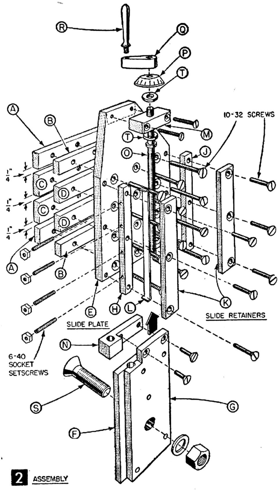
1 Lathe Milling Attachment By L C. MASON BY CLEVERLY stacking cold-rolled flat stock together, T-slots and slide for this lathe milling attachment are made without costly machinery. In fact, only two tools, a drill press and lathe, are needed to make the attachment. Shown mounted on the cross slide of a lathe (Fig. ), the attachment features a swivel base and tilting slide which has T-slots for clamping the work securely in place. Although this attachment was made for a 7-in. Atlas lathe, the overall dimensions could be increased 5% for use with a 9 or 0-in lathe. Start by cutting the stock size cold-rolled flat stock for T-slot pieces A, B, C and D in Fig. 3 to 3-in. lengths. Then lay out and drill the # holes. Pieces A and B, and C and D can be clamped together when drilling so that they will line up properly when assembling later. Next, hacksaw the slide plate E in Fig. 3 to shape and trim up the cut edges with a file. Lay out and scribe lines on the slide plate for locating pieces B and D. Be sure these lines are square with the sides of the slide plate. Clamp the B and D pieces to the slide plate and drill the # holes. Then open the holes with a #9 drill and countersink the holes on the back of the slide plate to sink 0-3 fh screws just below the surface. Tap the # holes in pieces A and C with 0-3 NF threads. Now cut the back plate pieces (F and G in Fig. 3) to length. Since stock size cold rolled Milling attachment in use on 7-in. lathe for milling out parts in the manifold of a model 4-cylinder gas engine. One holding clamp removed for clarity. does not come 3/6 and /6 in. wide, you will have to machine them. Clamp them on the lathe faceplate with a 90 angle block and turn the 3/6-in. piece about /64 in. undersize. Set these pieces aside for the moment, and make up and drill pieces H, J and K in Fig. 3. Note that the ends of piece H are filed to take the brass gib L, which should also be made up at this time. To assemble, first clamp piece J to the back and right side of the slide plate. The top and bottom screws securing piece J will run into the B pieces, so bolt these pieces on the front of the slide plate. Spot drill the slide plate through the #9 holes in piece J, then remove it and drill through with a # drill. Tap 0-3. To be certain of getting piece H parallel with piece J, place piece F between them. Be sure that the gib, piece L, is between pieces H and F also. Clamp piece H to the slide plate and test piece F to see that, it slides up and down smoothly. Then spot drill the slide plate through the holes in piece H and drill and tap as you did for piece J. Assemble the K pieces with the F piece in place. Now, place piece G, the other back plate you machined to /6 in. wide, on piece F between the K pieces. There should be /3 in. clearance on each side between the K pieces. Clamp the G piece in place, and drill the 3/6 in. rivet holes deep enough to spot drill the hole locations on 0 SCIENCE AND MECHANICS

2 the F piece. Then remove the pieces and continue drilling the holes through the F piece. Countersink the rivet holes on the F and G pieces a good /6 in. and fasten with rivets cut from 3/6 in. dia. soft steel rod. Heat rivets red hot before setting. When cool, file or grind flush at both ends. Your next step is to true up the front, or top surfaces of the T-slot pieces A and C so that they will be parallel with part G of the back plate that fastens to the angle on the lathe cross slide. First remove pieces H, J and K on the back of the slide plate. Then permanently fasten T-slot pieces A, B, C and D to the slide plate. File projecting 0-3 screws flush with A and C pieces. Reassemble the riveted back plate to the slide with pieces H, J, K and L. Tighten the screws so that the back plate will not slide. Now clamp the assembly to the lathe faceplate, so that the back plate is against the faceplate and T-slot pieces facing outward. Take a series of light cuts off the surfaces of pieces A and C, which will true up the front and compensate for any difference in the thicknesses of the flat bar stock. For the feed screw, make up piece M in Fig. 3 and fasten to the top of the slide plate with two 0-3 fh screws as in Fig.. Do not drill the ¼-in. hole in piece M at this time. Also make the nut, piece N in Fig. 3, and fasten to the top of piece G with two 0-3 fh screws. Since the holes for the feed screw through pieces M, N and the back plate must be aligned and parallel with the slide ways, clamp the assembly in the upright position on the drill press table so that the front of the slide plate and right side of the slide way is parallel with the drill bit. If the drill press has a tilting table, be sure to square the table with the drill bit first. Using a # drill, bore a hole through piece N and M, and into the back plates about ¼ in. in depth. The hole should land right between the riveted back plates. Remove the # drill, chuck a ¼- in. drill and bore through piece M only. Then, without removing the assembly from its clamped position on the drill press table, take off pieces M and N and bore a 9/3-in. hole 3 5/8 in. deep into the riveted back plates. While you have piece N off tap the # hole with 0-3 threads and reassemble to the back plate. Turn the feed screw, O in Fig. 3, from 3/8-in. steel rod, reducing the thread little by little until you have a shakeless fit with the nut. Note that the other end of the screw is threaded ¼-8 for the handle and dial. Turn the dial, P in Fig. 3, and scribe the graduations on the bevel with a screwcutting tool bit turned sideways in the

3 tool holder set at center height. Twentyfive divisions on the dial will indicate slide movement of.00 in. for each division. A 5-tooth gear fastened on the lathe spindle was used for indexing. Scribe every fifth line (.0) the full width of the bevel. Make the handle pieces Q and R as detailed in Fig. 3, and turn the thrust washers from bronze or brass. Before assembling the feed screw to the slide and back plate, turn the mounting bolt 5 in. (Fig. 3). Use a stock ½-0 hex. nut with the bolt. Then remove the back plate from the slide and bore the ½-in. hole, countersinking the widest of the back plates to the same taper as on the mounting bolt. Try to arrange the work so that the taper on the bolt and back plate can be turned without changing the angle of the lathe compound rest. When assembling the feed screw to bearing block M on the slide plate, place a thrush washer on the feed screw shaft at each side of block M. Then screw on the dial and handle on the feed screw, allowing just enough play for easy turning. With the handle and dial locked together like locknuts, hand solder or braze the handle to the dial. Drill a /6-in. hole through the handle and feed screw and drive a pin through it. Scribe an index mark on the slide plate as on E in Fig. 3. When assembling the mounting bolt to the back plate, file notches in the bolt heads as in Fig. 3. Then, after inserting the bolt in the back plate, raise burrs with a centerpunch at the edge of the hole to fill the filed notch. This will keep the bolt in place and prevent its turning. Now place the back plate in the slide ways, engage the feed screw and work it back and forth a few times to test the slide ways. If the K pieces are too tight, place a paper shim under each for clearance. If too loose, file or grind down the thickness of pieces H and J. Adjust the gib screws for a smooth sliding fit without play. The completed milling attachment mounts on a 3-in. length of 3/8 x 3 x 3-in. angle iron bolted to lathe cross slide in place of the compound rest as in Fig.. The size of this angle iron will vary depending upon the make and: model of the lathe it is to be used with. Regardless of the size of angle iron needed, first face off the two outside surfaces of the angle by clamping it on the lathe face plate with an angle block. Then cut a ¼ in. thick steel plate and rivet it to the inside surface of one leg of the angle as in Fig.. Again clamp the angle to the lathe face plate and bore a hole through the angle and ¼-in. plate large enough to fit on the compound mounting lug on the lathe cross slide. Clamp the angle iron to the lug in the same '

4 way the compound rest was clamped, drilling and tapping needed holes in angle iron, to take the plunger pins and clamp screws used to fasten the compound rest. To drill the ½-in. milling attachment mounting hole in the angle, clamp it so that the vertical face is exactly at right angles to the lathe bed ways and bore with a drill chucked in the lathe headstock. This will place the pivot point of the attachment on the lathe centerline which is advantageous for some types of milling operations. Work to be milled is clamped against the machined surface of the slide as in Fig.. Use ¼ in. squarehead machine bolts with heads placed in T slots for clamping.

5
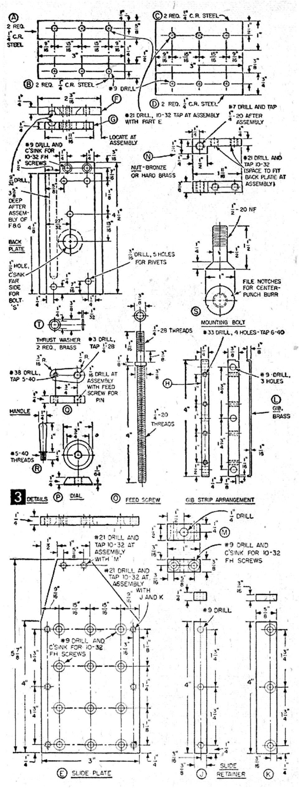
6 No. Req. 4 MATERIALS LIST MILLING ATTACHMENT All Dimensions in Inches Size and Description 3/6 x 5/8 x 4 cold rolled steel ¼ x 3/8 x 4 cold rolled steel ¼ x ½ x 3 cold rolled steel ¼ x 5/8 x 3 cold rolled steel ¼ x ¾ x 3 cold rolled steel ¼ x x 3 cold rolled steel ¼ x ½ x ¼ cold rolled steel ¼ x 3 x 5 7/8 cold rolled steel ¼ x ¼ x 4 /8 cold rolled steel ¼ x ¾ x 4½ cold rolled steel 3/8 x ½ x cold rolled steel dia. x ½ cold rolled steel 3/8 dia. x 8 cold rolled steel 3/8 x 3 x 3 x 3 long angle iron ¼ x x 3 cold rolled steel 3/6 dia. x 7 mild steel rod for rivets 3/8 x ½ x ¾ bronze or hard brass /6 x ¼ x 4½ hard brass 0-3 x 7/8 fh machine screws 0-3 x ¾ fh machine screws 6-40 x 5/8 headless flat-point socket setscrews 6-40 hex. nuts ½-0 hex. nut Use K H and J B A D C Q E F G M P and S 0 and R mounting angle mounting angle N L JUNE, 958

7
SHOP NOTES METAL SHAPER FOR YOUR SHOP
 SHOP NOTES METAL SHAPER FOR YOUR SHOP A METAL SHAPER is indispensable for certain machining operations where flat surfaces must be produced within very close limits, such as machining flats on castings,
The "DAVID" Steam Engine By Alan Marconett Hobbit Engineering HTTP://WWW.HobbitEngineering.com Alan@HobbitEngineering.
 The "DAVID" Steam Engine By Alan Marconett Hobbit Engineering HTTP://WWW.HobbitEngineering.com [email protected] (c) 2/20/03 The David steam engine is a simple oscillating steam engine, many plans
It's large enough to handle most welding job shop projects, yet small enough to make it a worth while home-workshop tool
 It's large enough to handle most welding job shop projects, yet small enough to make it a worth while home-workshop tool H Craft Print Project No. 272 ERE'S a metal bender that will enable you to bend
Make Your Own Gemstone Faceting Machine
 HOBBIES Make Your Own Gemstone Faceting Machine The art of lapidarypolishing stones to best display their qualitiesis an ancient one. With this motor-driven machine, you can do it effortlessly. u By MOODIE
METAL-TURNING LATHE Built from Stock Parts
 by Frank Beatty USING STANDARD PARTS and stock materials that are available almost anywhere, you can build this metalworking lathe with only a few tools. Because of simplification of the assembly in order
Model Marine Engine Requires No Castings
 Model Marine Engine Requires No Castings EXHAUST PORTS No. 29 No. 31 CROSSHEAD-GUIDE BRACKET No. 29 (STEAM PORT) CYLINDER BLOCK R CYLINDER COVERS No.31 CYLINDER SUPPORT No.29 (STEAM PORT) VALVE LINER VENT,
Resharpening Companion
 Resharpening Companion 10950 Correct Angles, Pictures, and Step-By-Step Instructions The Resharpening Companion is meant to be a guide and quick reference to help you resharpen. It is not meant to replace
MGB Chrome Bumper Conversion
 MGB Chrome Bumper Conversion Installation Instructions For 1974 1/2-1980 MGB This kit requires cutting, welding, and painting. Professional installation recommended. Note: Every MGB body is slightly different
The Bonelle Tool and Cutter Grinder
 The Bonelle Tool and Cutter Grinder The grinder was constructed about 1987 and exhibited at the 89th Model Engineering exhibition where it was awarded a bronze medal (see ME Vol164 No 3868 page 273). Subsequently
BUILDINGA 1/10 SCALE FLATBED TRAILER
 VOLUME 1, ISSUE 1 BUILDINGA 1/10 SCALE FLATBED TRAILER BUILT, DESIGNED & WRITTEN BY NATHAN MYERS MATERIALS: FEATURES: While the design was kept simple to allow anyone to be able to build their own trailer,
Building a Small Horizontal Steam Engine
 T Building a Small Horizontal Steam Engine HE small engine described in this article was built by the writer in his spare time about an hour a day for four months and drives the machinery in a small shop.
This little motorcycle has been designed
 MITE CYCLE You'll need only an "A" ration to run this midget motorcycle. by R. G. Fisher The Mite Cycle, with its builder, is shown above. A small one-cylinder engine provides the motive power. This little
RETROFITTING THE X3 MILLING MACHINE (2)
") RETROFITTING THE X3 MILLING MACHINE (2) Dick Stephen continues with the mechanical modifications. Fitting the ball screws The 12mm 2mm pitch supplied by THK ball screws are delivered with the nut fitted
RETROFITTING THE X3 MILLING MACHINE (2) Dick Stephen continues with the mechanical modifications. Fitting the ball screws The 12mm 2mm pitch supplied by THK ball screws are delivered with the nut fitted
STEADYfast Stabilizer Installation Notes Fifth Wheel and Travel Trailers 11/23/13
 STEADYfast Stabilizer Installation Notes Fifth Wheel and Travel Trailers 11/23/13 (See Supplemental Instructions for trailers with heavy duty round footplates and/or Power Leveling Systems) PHONE SUPPORT
How To Make A Spiral Fluted And Wire Wrapped Dagger Handle
 Making A Spiral Fluted and Wire Wrapped Dagger Handle By: Steve Culver, MS Part 1 Making A Spiral Fluted and Wire Wrapped Dagger Handle By: Steve Culver, MS After the rough handle material is drilled through
Gravity Racing Challenge STEM Team Competition Open Class High School Division Car Assembly Plans And Rules
 Gravity Racing Challenge STEM Team Competition Open Class High School Division Car Assembly Plans And Rules 1 Table Of Contents Introduction...Page 3 Floorboard...Page 4 Step One Steering Stop Installation...Page
Slide the new steering column shaft through the steering column from the driver compartment.
 Slide the new steering column shaft through the steering column from the driver compartment. Push the column shaft through the steering column until the machined end is out past the column lower bushing.
Where to order engine kits The displacer cylinder CONTINUED
 By Harry Walton OCUS sunlight on this model engine, and it runs at full speed, fueled by Fthe biggest nuclear reactor in the solar system the sun. Power is ample to drive a midget water pump or spin a
Router Table Plans. www.bobsplans.com
 www.bobsplans.com Router Table Plans Increase the capabilities of your router with this weekend project. Features a sliding fence with EZ-Mount clamps. These clamps are simple to make and grip tightly
Making Clock Wheel & Pinion Cutters
 Making Clock Wheel & Pinion Cutters When making hand made clocks or in repair work an odd size cutter is sometimes needed. Sometimes just one pinion is required and does not justify the cost of a commercial
Pump Skid Fabrication for Magnetic Coupling. Rick Soltis Chief Mechanic City of Bedford
 Pump Skid Fabrication for Magnetic Coupling Rick Soltis Chief Mechanic City of Bedford Contents Magnetic Couplings What They Are, How They Work, Where They re Used Fabrication and Manufacturing of Pump
Hive Top Ventilation Shims
 Hive Top Ventilation Shims When preparing your bee hives for the winter, it is very important to provide for ventilation at the top of the hive. Through out the winter, the bees are expelling a lot of
C O N V E Y O R C O M P O N E N T S C H A I N S B E L T S B E A R I N G S
 C O N V E Y O R C O M P O N E N T S C H A I N S B E L T S B E A R I N G S January 2009 Issue 6 Valu Guide Brackets The Ultimate in Adjustability and Cost Savings Valu Guide brackets are part of a family
KNIFE GRINDER MATERIALS LIST & CONSTRUCTION TIPS by Michael Clerc [email protected]
 KNIFE GRINDER MATERIALS LIST & CONSTRUCTION TIPS by Michael Clerc [email protected] Materials List Minimum tools required: Drill press & Drill bits ("#7", "F", 5 / 16 ", ¼", 17/64", ½", "O", 1") Tap Handle
THE ORIGINAL UNI-LOC PIN INSTALLATION PROCEDURE 321D REV03 5/19/08
 THE ORIGINAL UNI-LO PIN INSTALLATION PROEDURE 321D 03 5/19/08 1 UNI-LO Pins are best installed during the latter stage of finishing the butt. It is suggested to maintain less than.002 run-out in the front
Overview. Milling Machine Fundamentals. Safety. Shop Etiquette. Vehicle Projects Machine Shop
 Overview Milling Machine Fundamentals Wayne Staats, UW-Madison FSAE Safety Shop Etiquette Before Machining Indicating Calculating Feeds and Speeds Machining Maintenance Safety Respect the machines Common
AstroSystems Digital Setting Circles for Zhumell, GSO, Apertura and Astro-Tech
 AstroSystems Digital Setting Circles for Zhumell, GSO, Apertura and Astro-Tech Components 1 Sky Commander Digital Setting Circle Computer 2 Encoders 10,000 step 1 Sky Commander Digital Setting Circle Manual
Dismantling and Reassembly Guide
 Super X3 Mill Dismantling and Reassembly Guide A picture story book to help you dismantle and reassemble your Sieg Super X3 Mill Arc Euro Trade Ltd. 10 Archdale Street, Syston, Leicester, LE7 1NA. Web:
THE HOW AND WHY OF ADJUSTING A DEWALT RADIAL ARM SAW By Roger A. Hill
 THE HOW AND WHY OF ADJUSTING A DEWALT RADIAL ARM SAW By Roger A. Hill This is my 1531. Notice the Mr. Sawdust table and the dust box. The frame is bolted to the cabinet After over 40 years of using and
Black Wolf POCKET BILLIARD TABLE INSTALLATION MANUAL. SERVICE DEPARTMENT P.O. BOX 68 BRISTOL, WI 53104
 Black Wolf TM POCKET BILLIARD TABLE INSTALLATION MANUAL www.brunswickbilliards.com SERVICE DEPARTMENT P.O. BOX 68 BRISTOL, WI 53104 51-905710-000 SEPTEMBER 2010 NOTE: Please use the instructions in this
PREASSEMBLED ELEMENTS FOR LIFTING AND SLIDING DOORS
 SYSTEM COMPONENTS PREASSEMBLED ELEMENTS FOR FIFTING AND SLIDING DOORS s r ood gn i d i l s dna gn i t f i f r o f s t neme l e de l bme s s ae r P PREASSEMBLED ELEMENTS FOR LIFTING AND SLIDING DOORS These
Pole Lathe and Shave Horse Design
 Pole Lathe and Shave Horse Design These pictures and accompanying words are Copyright Michael Hughes February 2002. They are not to be re-produced, in part or whole, without permission from the author.
Twist Drill Grinding Attachment By Steven Skiprat Jackson June 2009
 Twist Drill Grinding Attachment By Steven Skiprat Jackson June 2009 Part 1. About the tool Part 2. Mounting the tool Part 3. Using the tool Part 1. About the tool This little gadget while not a precision
Precision made in Europe. As per DIN 8606. The heart of a system, versatile and expandable.
 1 von 9 Precision made in Europe. As per DIN 8606. The heart of a system, versatile and expandable. Main switch with auto-start protection and emergency off. Precision lathe chuck as per DIN 6386 (Ø 100mm).
Dive Rite 200 & 300 Bar Isolator Manifold Service Manual
 Dive Rite 200 & 300 Bar Isolator Manifold Service Manual Principal Photography and Text by Pete Nawrocky Copyright 2003 Lamartek Inc. D/B/A Dive Rite 0 Warning This manual is only to be used as a guide
ANSI APPROVED 04/11/2014 ANSI APPROVED 08/17/2011. 45 Reaffirmation ANSI APPROVED 02/28/2014. 45 Reaffirmation ANSI APPROVED 05/06/2013
 STANDARDS STATUS REPORT As of November 4, 2015 Note: Dates in RED indicate the last action taken; Highlighted Items Indicate New/Open Items; Grey items have been closed Document TC Status Comments ASME
COLLEGE OF ENGINEERING AND APPLIED SCIENCE MACHINE SHOP TOOLS AND PRACTICES
 COLLEGE OF ENGINEERING AND APPLIED SCIENCE MACHINE SHOP TOOLS AND PRACTICES I. OBJECTIVE To provide an overview and basic knowledge of the University of Wyoming, College of Engineering, equipment, tools,
Chapter 3 Installing Over-the-Post Railing on an L-Shaped Stair
 49 Chapter 3 Installing Over-the-Post Railing on an L-Shaped Stair In this chapter: The Over-the-Post Balustrade System Determining the Rail Centerline Using Rail Bolts Making a Pitch Block Laying Out
I BEAM TRACK INSTALLATION
 PDQ 0/700 FESTOON SYSTEM INSTALLATION AND MAINTENANCE INSTRUCTIONS INTRODUCTION The PDQ Festoon System was designed to run on one of three sizes of I-beams: S x., S8 x 8. and S x.. System trolleys must
www.cornholesupplies.com
 www.cornholesupplies.com How To Build Regulation Cornhole Boards Home of the Original Cornhole Bags and Boards Supply List: 1-4' X 8' Piece of Plywood (pre sanded) 4-2" X 4" X 8' Studs (2 by 4s make sure
TECHNICAL INFORMATION
 TECHNICAL INFORMATION Models No. 2012NB Description 304mm (12") Automatic Thickness Planer CONCEPTION AND MAIN APPLICATIONS * Compact and light weight (27 Kg./59 lbs) automatic thickness planer for easier
3000, 4000, 4100, 7500, 7700
 3000, 4000, 4100, 7500, 7700 Drum & Disc Brake Lathes s Identification READ these instructions before placing unit in service. KEEP these and other materials delivered with the unit in a binder near the
Rebuild Instructions for 70001 and 70010 Transmission
 Rebuild Instructions for 70001 and 70010 Transmission Brinn, Incorporated 1615 Tech Drive Bay City, MI 48706 Telephone 989.686.8920 Fax 989.686.6520 www.brinninc.com Notice Read all instructions before
SPRITE and BIGFOOT DESKTOP CNC MACHINE KIT ASSEMBLY INSTRUCTIONS
 SPRITE and BIGFOOT DESKTOP CNC MACHINE KIT ASSEMBLY INSTRUCTIONS README FIRST: Thank you for purchasing your MyDIYCNC Desktop CNC Machine Kit. We hope this versatile and innovative machine brings you many
FRONT BUMPER INSTALLATION INSTRUCTIONS 2007-2011 DODGE / MERCEDES SPRINTER
 Aluminess Products Inc 9402 Wheatlands Ct. #A Santee, CA 92071 619-449-9930 FRONT BUMPER INSTALLATION INSTRUCTIONS 2007-2011 DODGE / MERCEDES SPRINTER Please read before beginning Stainless steel hardware
BUILD A TABLETOP LOOM
 BUILD A TABLETOP LOOM From 1" x 2" stock (actual 3/4" x 1"1/2) cut: 4 pieces 15" long 4 pieces 5"1/2 long Use the above to make 2 frames for the front and back of the loom. From 1" x 4" stock (actual 3/4"
Model 60L. 2) Click on appropriate Service Notice
 Click on appropriate Service Notice") Service Notices Model 60L 1) Select the Bookmark option 2) Click on appropriate Service Notice Service Notice Numbering and Tracking System The following layout is using a single part number for reference
Service Notices Model 60L 1) Select the Bookmark option 2) Click on appropriate Service Notice Service Notice Numbering and Tracking System The following layout is using a single part number for reference
YUASA MILLING MACHINE ACCESSORIES & TOOLS
 97 HORIZONTAL / VERTICAL 5C COLLET INDEX 550 series 2 YEAR WARRANTY Spindle is manufactured with a taper seat in body frame. Rapid opening and closing is performed with a level collet closer with a leverage
Formula World GT 200 DRAFT COPY WWW.TEAMSPEEDMERCHANT.COM. f200.0.0d
 DRAFT COPY WWW.TEAMSPEEDMERCHANT.COM f200.0.0d 2 Introduction, Supplies and Additional Equipment Congratulations on your purchase of a Speed Merchant Formula World GT 200 competition chassis. This instruction
FTC 2015-2016 DIY Mountain Build Guide
 FTC 2015-2016 DIY Mountain Build Guide Assembly Instructions Check out the DIY2015-2016 Prints and BoM for individual part details. Release 1.0 9/10/15 Page 1 This guide and Bill of Materials are for constructing
Fixturing systems Fixturing systems for measurement technology
 Fixturing systems Fixturing systems for measurement technology Innovations and new additions to range Sets Spannfix Eco complete set The set contains different supports, extension elements and stop units.
Working Drawing and Assemblies. Chapter 10
 Working Drawing and Assemblies Chapter 10 Objectives 1.Define working drawings. 2. Describe how working drawings are used in industry. 3. List the major components of a complete set of working drawings.
How to Build a Poker Table
 How to Build a Poker Table www.pokertablematerials.com 10-Person Poker Table- 96 x 48 These are step by step instructions for building a poker table. The table will measure 48" x 96" and have a 4" wide
INSTRUCTIONS AND PARTS LIST FOR MODEL 70H & 75H HAND-OPERATED HYDRAULIC PRESS
 INSTRUCTIONS AND PARTS LIST FOR MODEL 70H & 75H HAND-OPERATED HYDRAULIC PRESS SETTING UP THE PRESS FOR OPERATION For shipping convenience, the gauge, pump handle, hoist crank, screw nose and base angles
Telescoping Post Indicator Wall Post KENNEDY VALVE ISO 9000 ISO 14001
 Telescoping Post Indicator Wall Post KENNEDY VALVE ISO 9000 ISO 14001 Telescoping Post Indicator 2945 A 1" SQUARE STEM 9" MAX. = 10" MIN. = 7" FIELD ADJUSTMENT INSTRUCTIONS 1. Remove the top section from
American National, Unified Screw Threads
 C h a p t e r 9 American National, Unified Screw Threads In this chapter, you will learn the following to World Class standards:! Why Use Fasteners! The Text Designation for the Unified National Thread!
INSTRUCTION MANUAL AND PARTS LIST MODEL 14-10
 VERTICAL BAND SAWS INSTRUCTION MANUAL AND PARTS LIST MODEL 1-10 DAKE/PARMA WHEN ORDERING PARTS GIVE COMPLETE SERIAL NUMBER OF MACHINE GIVE PART NUMBER AND NAME GIVE AMOUNT REQUIRED Unless the above data
HOW TO MAKE A MOTOR BRACKET
 HOW TO MAKE A MOUNTING BRACKET FOR AN ELECTRIC MOTOR Often, brackets supplied with purchased items (e.g. electric motors or servos) are not ideally suited for fitting into our models or they are not supplied
No. 57 Receiver Sight No. 57 SML Receiver Sight No. 66 Receiver Sight
 No. 57 Receiver Sight No. 57 SML Receiver Sight No. 66 Receiver Sight MOUNTING AND ADJUSTING MOUNTING LYMAN NO 57 RECEIVER SIGHT The No. 57 Sight is designed primarily for rifles with round receivers.
2100 AD 015 0009 Mirror Elevator Ball Nut Replacement Procedure
 2100 AD 015 0009 Mirror Elevator Ball Nut Replacement Procedure Derek Guenther 1/28/2015 Rev. Purpose The purpose of this document is to describe the procedure necessary to replace one of the ball nuts
Assembly Instructions Model 1544 Heart-Of-The-Kitchen Island
 Assembly Instructions Model 1544 Heart-Of-The-Kitchen Island A. These units are Ready-to-Assemble. Catskill uses positive fastening methods such as wood screws and in some places hidden Bastion fasteners.
INSTALLATION INSTRUCTIONS. 6108 Air Spring Kit 2011+ Ford F250 Single Wheel 4WD 2011+ Ford F350 Dually 4WD (2011 F350 Single Wheel 4WD use p/n 6113)
") INSTALLATION INSTRUCTIONS 6108 Air Spring Kit 2011+ Ford F250 Single Wheel 4WD 2011+ Ford F350 Dually 4WD (2011 F350 Single Wheel 4WD use p/n 6113) Thank you for purchasing a quality Hellwig Product. PLEASE
INSTALLATION INSTRUCTIONS 6108 Air Spring Kit 2011+ Ford F250 Single Wheel 4WD 2011+ Ford F350 Dually 4WD (2011 F350 Single Wheel 4WD use p/n 6113) Thank you for purchasing a quality Hellwig Product. PLEASE
Speed-Mat Rectangle Cutter
 Speed-Mat Rectangle Cutter 1 Honeycomb baseboard. 2 Left hold down. 14 3 Bottom hold down. 4 4 Left / right rule. 8 5 8 5 Left / right rule pointer. 1 6 Top / bottom rule. 7 Top / bottom rule pointer.
DTU Animal Cart Programme
 DTU Animal Cart Programme TECHNICAL 21 RELEASE PIPE AND ROLLER DONKEY CART AXLES Development Technology Unit, Department of Engineering, University of Warwick, Coventry, CV4 7AL UK, tel: +44 (0)1203 523523
Modular Locomotive System Instruction Manual for HBK8 George Body Kit
 Modular Locomotive System Instruction Manual for HBK8 George Body Kit Roundhouse Engineering Co. Ltd. Units 6-10 Churchill Business Park. Churchill Road, Wheatley. Doncaster. DN1 2TF. England. Tel. 01302
UNITED STATES CUTTING TOOL INSTITUTE Product Groupings for Standards Activities CUTTING TOOL PRODUCTS
 CUTTING TOOL PRODUCTS 1. BORING ISO 5609 Boring bars for indexable inserts Dimensions ISO 6261 Boring bars (tool holders with cylindrical shank) for indexable inserts Designation JIS B 4128 Boring bars
SERVICE PARTS LIST PAGE 1 OF 6 BASE ASSEMBLY SPECIFY CATALOG NO. AND SERIAL NO. WHEN ORDERING PARTS 12" DUAL BEVEL COMPOUND MITER SAW B27A
 PAGE 1 OF 6 BASE ASSEMBLY 00 0 EXAMPLE: Component Parts (Small #) Are Included When Ordering The Assembly (Large #). SPECIFY CATALOG NO. AND NO. WHEN ORDERING PARTS 1 02-80-0050 Thrust Bearing (1) 2 05-80-0510
Children s Furniture Projects
 This is an excerpt from the book Children s Furniture Projects by Jeff Miller Copyright 2002 by The Taunton Press www.taunton.com CHILD S ROCKER KIDS ARE ALWAYS IN MOTION. It s not easy to get them even
Vinyl Brick Mould Field Installation Instructions All Vinyl and Vinyl Clad Windows
 Vinyl Brick Mould Field Installation Instructions All Vinyl and Vinyl Clad Windows Viewed from the exterior. IMPORTANT: Please read before you begin installation. TABLE OF CONTENTS AND TOOL / MATERIAL
STEERING HANDLEBAR/FRONT WHEEL/ FRONT SHOCK ABSORBER
 14 14 STEERING HANDLEBAR/FRONT WHEEL/ SCHEMATIC DRAWING ------------------------------------------------- 14-1 SERVICE INFORMATION------------------------------------------------ 14-2 TROUBLESHOOTING-----------------------------------------------------
Cedar Cottage Doghouse Plans
 Overlapping cedar shingles add an element of charm to this medium size doghouse. The walls, floor, and trim are constructed of solid cedar, making it naturally weather resistant and provides excellent
Number Wheeler P/N Description Set Rex P/N Notes
 1 607051 Base 1 A050 2 607052 Motor Cover 1 A052 3 600778 Socket Hd Cap Screw (M8x60) 2 4 607053 Scrap Receiver 1 A053 5 607054 Tank Upper Cover 1 A054 6 607055 Oil Pot 1 A055 7 607056 Strainer 1 A056
CAST IRON THE BASICS. Heatline - Cast Iron Radiators SMOOTH FLAT FILE TO REMOVE ANY SWARF. ONE TIME. ASSEMBLY. JOINTS SHOULD BE TIGHTENED.
 CAST IRON THE BASICS 1. DO NOT LIFT ON YOUR OWN. 2. ONLY LIFT THE RADIATOR VERTICALLY. 3. DO NOT LIFT MORE THAN 8/10 SECTIONS AT ANY ONE TIME. 4. POSITION THE RADIATOR BEFORE FINAL ASSEMBLY. 5. THIS PRODUCT
Machine Screws, Dowel Pins and Hardware
 Machine Screws, Dowel Pins and Section Contents Plain Socket Head Screws...Page 13-2 Wire Locking Screws...Page 13-3 Captive Screws...Page 13- Ventilation Screws...Page 13- Shoulder Screws...Page 13-
HONING LATHE DUPLICATOR CUTTERS
 Lay the flat face of the cutter or bit on the flat top surface of the hone with the rest of the cutter overhanging the edge. Rub the cutter or bit up and down the hone (Figure 24-44). Be sure to hold the
Verify caster, camber and toe-in are correct before proceeding.
 If rotating the tie rod end 360 degrees changes the toe-in too much, use the rack tie rod to make smaller adjustments. Put the tie rod end in the steering arm and snug the castle nut before adjusting.
Technical Information
 Technical Information This section of the catalogue provides technical information that will help specify, install and maintain Surelock McGill devices and components. The topics are listed below: Blast
Common Mechanical Engineering Terms
 Common Mechanical Engineering Terms Ball and Detent (n) A simple mechanical arrangement used to hold a moving part in a temporarily fixed position relative to another part. The ball slides within a bored
INSTRUCTIONS THOROUGHLY BEFORE BEGINNING***************
 Bill of Materials: RAC0012 Green Wing Aerodynamic Skirt Kit Item Part Number Description Quantity 1 RMC0218 Gen 2 Trailer Skirt Roadside 1 2 RMC0219 Gen 2 Trailer Skirt Curbside 1 3 RMC0041 Trailer Skirt
1.8 CRANKSHAFT OIL SEALS
 SERIES 60 SERVICE MANUAL 1.8 CRANKSHAFT OIL SEALS An oil seal is fitted between each end of the crankshaft and the bores of the flywheel housing and gear case cover to retain the lubricating oil in the
OWNER S MANUAL Table Tennis Table Patent Pending
 OWNER S MANUAL Table Tennis Table Patent Pending Be sure to write your model number and serial number here for future reference. You can find these numbers printed on the bottom of the table. MODEL # T8179
INSTALLATION INSTRUCTIONS. 6111 Air Spring Kit 2011+ Ford F250/F-350 Single Wheel 2WD 2011+ Ford F350 Dually 2WD IMPORTANT NOTES
 INSTALLATION INSTRUCTIONS 6111 Air Spring Kit 2011+ Ford F250/F-350 Single Wheel 2WD 2011+ Ford F350 Dually 2WD Thank you for purchasing a quality Hellwig Product. PLEASE READ THIS INSTRUCTION SHEET COMPLETELY
INSTALLATION INSTRUCTIONS COMPETITION SERIES COILOVER SUSPENSION SYSTEM 03+ Scion xb
 INSTALLATION INSTRUCTIONS COMPETITION SERIES COILOVER SUSPENSION SYSTEM 03+ Scion xb NOTE: Progress Technology products should only be installed by a qualified licensed mechanic experienced in the installation
SLACK PERFORMANCE KARTS
 SLACK PERFORMANCE KARTS SET UP GUIDE Thank you for purchasing a 2013 Slack Axiom Chassis. Performance Mfg. strives to provide you with the very best chassis and components on the market today. Your satisfaction
TRANS-05, Torque Tube Removal, Rebuilding, and Installation
 TRANS-05, Torque Tube Removal, Rebuilding, and Installation Tools Metric Wrench Set Metric Socket Set Jack Stands (6 minimum) Floor Jack 8mm Cheesehead socket (also referred to as 12 point internal socket
RadianceRail Installation Guide
 RadianceRail Installation Guide Installing RadianceRail with CableRail by Feeney... 2 Installing CableRail by Feeney for RadianceRail... 7 Installing RadianceRail Stairs with CableRail by Feeney... 10
Char-Lynn Spool Valve Hydraulic Motors. Repair Information. W Series Geroler Motors
 Char-Lynn Spool Valve Hydraulic Motors Repair Information W Series Geroler Motors with Parking Brake 004 Nut Key Ring, Retaining Bearing Ring, Retaining Ring, Retaining Washer (Thick), Pressure Washer,
STORAGE, INSTALLATION AND MAINTENANCE PROCEDURES
 GATE VALVE O.S. & Y 1.0 Periodic Inspections 1.1 The valve stem packing should be inspected at least monthly. If the stem packing shows signs of leakage, simply tighten the adjusting nuts to compress the
PRS Y-axis EChain Installation
 PRS Y-axis Energy Chain Installation Page -1- PRS Y-axis EChain Installation This document shows how to install the Energy chain (Echain) on the Y-axis on ShopBot PRS and PRS BT models. Note that the dust
Number Wheeler P/N Description Set Rex P/N Notes 1 603500 Base 1 J001 2 603501 Support, Right 1 J002 3 603502 Support, Left 1 J003 4 600328 Nut (M8)
") 1 603500 Base 1 J001 2 603501 Support, Right 1 J002 3 603502 Support, Left 1 J003 4 600328 Nut (M8) 4 5 600130 Spring Washer (8mm) 4 6 600344 Roll Pin (M6x30) 4 7 600129 Socket Hd Cap Screw (M8x25) 4 8
1 603500 Base 1 J001 2 603501 Support, Right 1 J002 3 603502 Support, Left 1 J003 4 600328 Nut (M8) 4 5 600130 Spring Washer (8mm) 4 6 600344 Roll Pin (M6x30) 4 7 600129 Socket Hd Cap Screw (M8x25) 4 8
Making Soft Jaws for a Bison 3 Jaw Lathe Chuck
 Making Soft Jaws for a Bison 3 Jaw Lathe Chuck By R. G. Sparber Copyleft protects this document. 1 My Bison lathe chuck has served me well for many years. One of its features is the ability to remove the
INTRODUCTION KINGPIN REPLACEMENT
 KINGPIN REPLACEMENT Author: Randy Baumann All information, illustrations and specifications are based on the best information available at the time of publication. The author cannot guarantee the accuracy
Parts#MB003-003 Reverse Gear MAMBA (Monoblock for Cable operated) For 5 speed Trans., '87 to '06 Big Twin models (except '06 Dyna)
 For 5 speed Trans., '87 to '06 Big Twin models (except '06 Dyna)") Installation Instructions Reverse Gear MAMBA (Monoblock for Cable operated) Read and become familiar with these installation instructions before start. Two Piece for H-D 5 Speed Trans., Cable operated
Installation Instructions Reverse Gear MAMBA (Monoblock for Cable operated) Read and become familiar with these installation instructions before start. Two Piece for H-D 5 Speed Trans., Cable operated
Mercedes 722.3 722.4
 96 Mercedes 7. 7. 5 6 7 8 - Clutch K - Brake Band B - Disc Brake B - Wide Planet Pinion 5 - One-Way Clutch F 6 - Clutch K 7 - Brake Band B 8 - Narrow Planet Pinion Int. Band Fwd. Band Rev. Clutch Direct
Mould and Die Standard Parts
 Mould and Die Standard Parts Tampere University of technology - Tuula Höök Mould standard parts can be divided into the following groups: Standard mould set with guide bars, guide sleeves and other guiding
INSTALLATION AND OPERATING INSTRUCTIONS For Model GL1 Gate Locks
 Securitron Magnalock Corp. www.securitron.com ASSA ABLOY, the global leader Tel 800.624.5625 [email protected] in door opening solutions INSTALLATION AND OPERATING INSTRUCTIONS For Model GL1 Gate
VCE VET ENGINEERING STUDIES
 Victorian Certificate of Education 2013 SUPERVISOR TO ATTACH PROCESSING LABEL HERE STUDENT NUMBER Letter Figures Words VCE VET ENGINEERING STUDIES Written examination Section Wednesday 20 November 2013
Original Assembly Guide
 TCT Multipurpose Single Bevel Sliding Compound Mitre Saw Original Assembly Guide Read instructions before assembling this tool. Table of Contents GB Assembly Guide Read instructions before assembling this
How to Build Your Own CornHole Game
 How to Build Your Own CornHole Game DIMENSIONS Here is a diagram with the basic measurements for the Cornhole board game. SUPPLIES 1/2 thick sheet of plywood one 4 x4 or two 2 x4 s 8 long 2 4 s (4) 4 1/2