The Pass Zen Amplifier: 10 Watts of Single-Stage Single-Ended Class A
|
|
|
- Sherman Higgins
- 10 years ago
- Views:
Transcription
1 The Pass Zen Amplifier: 10 Watts of Single-Stage Single-Ended Class A I. "What is the sound of one transistor clapping?" There are two most essential principles to audio amplifier design. The first is simplicity. The second is linearity. Einstein said, "Everything should be made as simple as possible, but no simpler." Simplicity is a common element of the best and most subtle designs. It is preferred for purely aesthetic reasons, but also because fewer elements color the sound less, and lose less information. Many audiophiles, including myself, are willing to sacrifice other areas of performance to achieve the intimacy with the sound available through a simple circuit. An amplifier should be simple, but it also must be linear. Some measure of distortion in an amplifier is unavoidable and forgivable if it is of a less offensive type, but still it is important that the measured distortion performance be reasonably low. The advantage of a simple circuit is lost if the sound is overlaid with an excess of false coloration. Many complex topologies have been justified by high quality of measured performance. By objective criteria, this is a perfectly valid approach. There are many applications where the need for measured precision is important and subjective performance is unimportant. Any application where the performance is crucial to obtaining accurate numbers, such as in an MRI field amplifier, should be judged by objective means. But this is not rocket science; our objective is to make listeners enjoy sound. If we justify this approach by calling it art instead of science, that is perfectly fine, even preferable. Resolving the apparent conflict between simplicity and objective performance is our goal. Commercially available power amplifiers have as many of 7 gain stages in series. The simplest I know of still has 3 stages. This succession of gain stages is essential to build up excess gain that can be used for negative feedback. The feedback is used to correct the performance of the gain stages. Paradoxically, the extra gain is used to correct the extra distortion of the additional gain stages. How simple can we make a circuit and still have it perform well? Obviously an amplifier with a single gain stage will be about as simple as we can topologically create, and we ask the question, "How much performance can we get out of a single gain device?" II. Single Ended Class A Only one approach is available for linear performance from such a simple circuit: Single-Ended Class A. It was the topology in the earliest use of gain devices (tubes, of course), but has not been widely employed in the output stages of solid state power amplifiers due to its energy inefficiency.

2 Single-Ended Class A operation has received increased attention lately, primarily from tube enthusiasts, and recently a number of companies have introduced tube SingleEnded Class A amplifiers. They are characterized by limited power, high cost, and multiple gain stages. I published a 20 watt bipolar Single-Ended Class A design in 1977 in Audio Magazine, and it had four gain stages. Pass Labs has been manufacturing the Aleph series of Single-Ended Class A amplifiers since 1992, and they have three gain stages. I am unaware of other solid state offerings in the US, although I expect that my hegemony will be short-lived, with the imminent appearance other single-ended transistor amplifiers. Simplicity is not the only reason for the use of the single-ended topology. The characteristic of a single-ended gain stage is the most musically natural. Its asymmetry is similar to the compression / rarefaction characteristic of air, where for a given displacement slightly higher pressure is observed on a positive (compression) than on a negative (rarefaction). Air itself is observed to be a single-ended medium, where the pressure can become very high, but never go below 0. The harmonic distortion of such a medium is second harmonic, the least offensive variety. It is occasionally misunderstood that single-ended amplifiers intentionally distort the signal with second harmonic in order to achieve a falsely euphonious character. This is not true. Low distortion is still an important goal, and it is my observation that deliberate injection of second harmonic into a musical signal does not improve the quality of sound. Single-ended amplification is distinct from push-pull designs in that there is only one gain device for each gain stage, and it carries the full signal alone. Linear singleended designs operate only in Class A. In contrast, push-pull designs share the signal between two opposing devices, one concentrating on the positive half, the other the negative half. This positive/negative half of an audio signal is an artifice imposed by the desire to efficiently handle an AC only signal, with no DC component. Most Push-pull Class A designs offer energy efficiency of twice that of most single-ended designs, and they also offer a measure of distortion cancellation. A well matched push-pull pair of gain devices will have lower measured distortion due to cancellation, and will concentrate the harmonic content into third harmonic and other "odd" harmonics, reflecting the symmetry between the plus and minus halves of the waveform. Operation is possible in Class A, Class AB, and Class B modes. The most linear of these is Class A, in which the circuit will dissipate at idle more than twice its rated output. Push-pull circuits have higher efficiency, and they also have an advantage in being able to source current in excess of the idle, or bias, current, by dropping into a lower class of operation. A Push-Pull Class A amplifier idling at a 1 amp bias current can deliver 2 amp peaks before leaving Class A, and can deliver still higher currents considered as a Class AB amplifier, where one half of the amplifier experiences cutoff, and does not carry the signal for a portion of the waveform. By contrast, Single-Ended Class A amplifiers cannot linearly deliver current beyond their bias point,

3 and they generally must dissipate at idle more than 4 times their rated output. Typical efficiency is about 20% maximum. This tremendous inefficiency alone explains why Single-Ended Class A has received limited attention, although careful consideration of possible circuits reveals that efficiencies approaching 50% are possible. In addition, there are ways in which a Single-Ended Class A amplifier can be operated as a push-pull device beyond its bias point, the assumption being that push-pull performance is preferable to clipping. Pass Labs has received one patent and has an application for another reflecting new developments in this area. Figure 1 shows a simple example of a Single-Ended Class A circuit. In this case the gain device is a FET, although the concept applies equally well for a tube for bipolar transistor. The input signal is applied at the gate, and the transistor provides current and voltage gain which appears at the drain. The gain stage is biased by some form of impedance which sources the bias current to the transistor. This impedance might be a resistor, or it might be a constant current source, or it might be some other load, such as a loudspeaker. Because this element carries the DC bias current, it is unlikely that we would want to use a loudspeaker for this, and typically we would want to attach the loudspeaker in parallel with the bias element, in series with a blocking capacitor.

4 If the bias element is a resistor, we see a typical efficiency of about 4%. This means we idle the circuit at 100 watts and have a maximum output of 4 watts. We can dramatically improve the efficiency if we separate bias current from signal current, so that the bias source handles purely DC, and of course our blocking capacitor insures that the speaker sees only the AC portion of the signal. We can achieve this by biasing the circuit with a constant current source and the efficiency climbs to about 20%, or about 5 times better. The constant current source provides only DC current which does not vary with the signal. In addition to the improvement in efficiency, the constant current sources removes power supply noise from the bias and provides an absolutely constant load for the power supply. As a result of this absolutely constant power supply draw, it becomes relatively unimportant what resistance is seen in the power source circuit, and two channels can draw off of one supply without modulating each other's signal. Clearly the use of a constant current source for the bias is justified by the performance over the use of a resistor, although not every single-ended designer agrees. III. Mosfets We have to consider what type of gain device is suitable for this application. Actually the choice is simple: Bipolar devices have too low an input impedance to be useable, and tubes have too little gain to be used in a single stage power amplifier. The only usable device is the power Mosfet, which is a transconductance device like the tube, and has a high input impedance, but operates with enough gain at high enough currents to be driven directly by line-level signal. As a coincidence, the Mosfet happens to be my gain device of choice in general. Even in more complex circuits Bipolar transistors do not have the transconductance characteristic I find desirable, and tubes require a coupling transformer, with its attendant degradation. The use of transformers as a load for a single-ended circuit is very problematic, since the DC current passing through the transformer tends to saturate the core. The solution that has been employed is to use a core with an air gap, wish' the result that the primary and secondary coils become only loosely coupled, with performance suffering even more. Mosfets have not been adequately appreciated for their characteristics in high end audio. I believe this is due to the relatively lackluster sound associated with the commercial offerings to date. This is not the fault of Mosfets, however. Examination of the amplifiers on the market reveal two serious flaws in how Mosfets are being used for amplification. First, nearly all designers simply dropped Mosfets into the same (complex) topologies that were developed for bipolar devices without regard for their special characteristics. This unimaginative use of a new gain device results in a sound that is marginally different than the original bipolar circuit, and not much of an improvement. The Mosfet designs on the market are also Class AB designs. The transfer curve of Mosfets reveals serious nonlinearities at low bias currents, resulting in crossover nonlinearity in push-pull

5 designs. This design flaw makes for a sonic signature that many have referred to as "Mosfet mist", where a loss of detail is apparent. To fully realize the benefits of Mosfet transistors, they must be operated in Class A. So it is not surprising that Mosfets have not found the favor among audiophiles that the devices deserve. I expect this to change in the near future, particularly as Mosfets find their way into single-ended Class A amplifiers. IV. The Circuit. Figure 2 reveals the complete circuit of the amplifier. Q1 is the gain stage, biased by the constant current source of Q2. Dealing first with the current source, we note the circuitry associated with Q2. Q3 is used to regulated the gate drive for Q2. It is fed current (biased) by R6/R7, with C5 used to filter out power supply ripple. As current passes through Q2, it develops a voltage drop across R1, and when this voltage drop reaches about.66 volts (2 amps through Q2/R1), it turns on the junction of Q3, and Q3 then limits the voltage appearing at the gate of Q2 to about 4 volts. This little loop operates to keep the current through Q2 at a constant 2 amps. R3 and R4 are there to add stability to the loop and prevent parasitic oscillation of the Mosfet Q2.

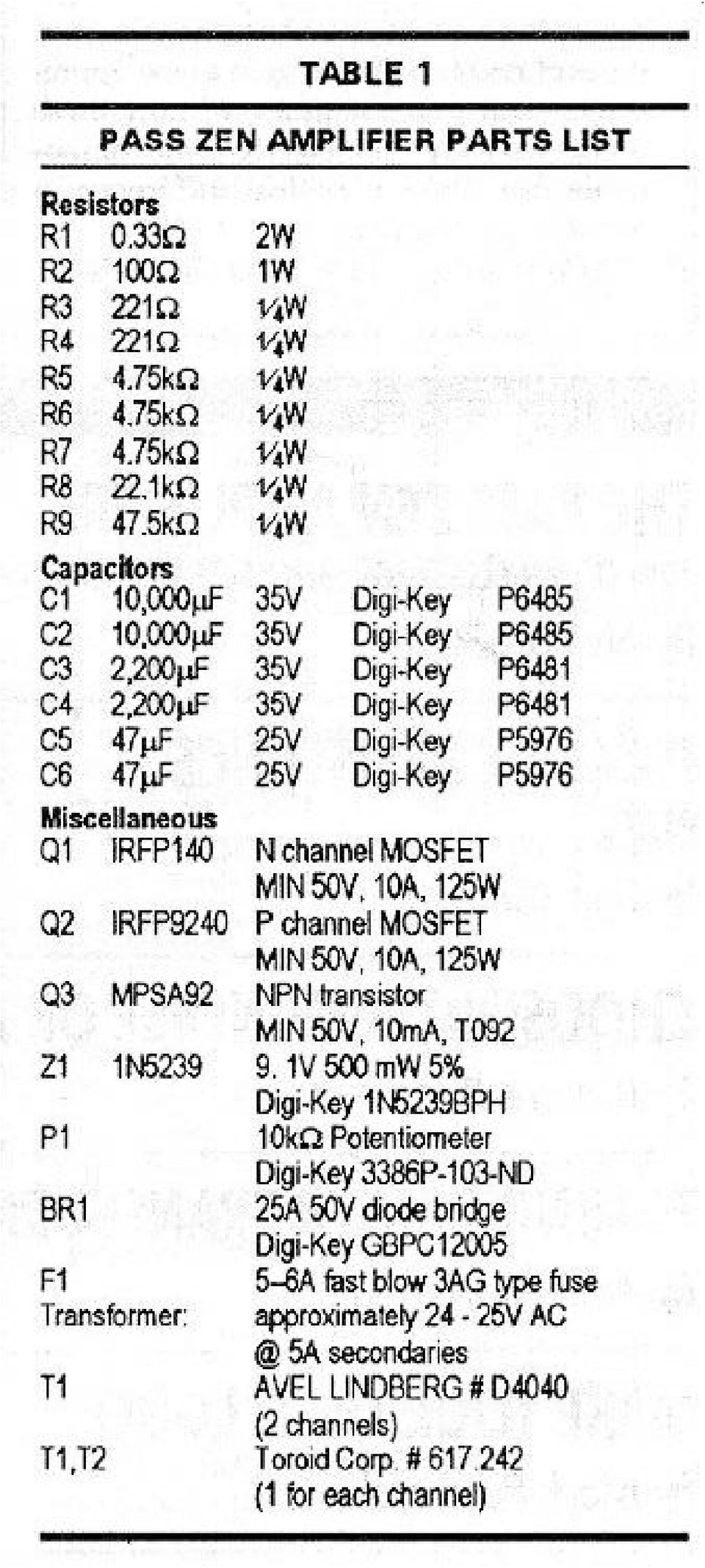
6 This constant 2 amp current is fed to Q1. Resistor R8 and potentiometer P1 form a DC feedback loop which operates the gate of Q1 at about 4 volts and places the Drain potential of Q2 at the midway point of the power supply, or about 17 volts. Input signal passes through C6 and R5 to the gate of Q1, and output signal passes through C3 and C4 in parallel to the loudspeaker. R9 and R2 are there to bleed off DC, but are not particularly essential. Z1 is essential to insure that an input transient cannot exceed the 20 V gate rating of the Mosfet. Fig 3 shows the PC artwork for two channels. The pattern is for single-sided (of course!) construction, but I had boards made with a ground plane on the top side of the board and plated through holes, since the difference in cost is very slight. Note that the output connections appear to be reversed in polarity. Because the topology reverses polarity, the loudspeaker plus terminals should be attached to ground and the minus terminals are attached to the active output of the amplifier. Fig 4. shows the component placement, Fig 5 is the parts list. Note that the transformer T1, the fuse F1 and the diode bridges B1 are not on the PC board. The board connections labels L POWER and R POWER attach to the diode bridge + and -. Part substitutions are certainly possible. The first requirement for the Mosfets is the ability to dissipate 30 watts continuously without failure, which means selecting devices rated at 125 watts

7 or more. The Mosfets must be rated at 50 volts or more, and I suggest that they be rated at continuous drain currents of 10 amps or more. I have chosen International Rectifier parts in this case, and numerous substitutions will meet these requirements on the IR page of the Digikey catalog. A very important element is the heat sink. The sink for each channel must be capable of dissipating 70 watts continuously at a temperature increase of about 25 degrees Centigrade. Less heat sink will shorten the life of the Mosfets. If you find that you can't touch the heat sink in operation, I suggest the use of a fan. The power transformer should source about 25 volts AC at 6 amps or so for each channel. While the actual DC draw is exactly 2 amps per channel, the power factor created by charging the power supply capacitors results in transformer dissipation greater than suggested by the 2 amps. From Fig 5 you can see that the suggested power transformer has a secondary coil for each channel, however it is acceptable to drive both channels from a single secondary and diode bridge.

8

9
10 V. Operation When you have completed the construction, plug it in. If the power supply fuse does not blow, you will be looking for about.66 volts across R1, no DC voltage at the output, and about 17 volts at the drains (center pins) of the Mosfets. With an input signal and an 8 ohm load, adjust P1 for symmetric clipping. Readjust P1 after the amplifier has warmed up. Fig 6 shows the harmonic distortion curve from 10 milliwatts to 20 watts at 1 Khz and 8 ohms. Below 10 watts the distortion is purely second harmonic. Fig 7 shows the distortion at 2 watts across the audio band. Fig 8 shows the frequency response. The amplitude is about.25 db down at 20 Hz and about.5 db down at 20 Khz. The output impedance of the amplifier is approximately 1 ohm, with a damping factor of about 8. There will be loudspeakers that are not suitable loads for this amplifier, either because they need high damping factor, have an impedance below 8 ohms, or require more than 10 watts. At impedances below 8 ohms, the output of the amplifier will not increase, it will drop off. This is because the single-ended design can source only the value of the bias current, and will not operated linearly beyond the bias point. There are quite a few loudspeakers with 8-16 ohm impedances and sensitivities in the db range which are quite suitable. The amplifier is also quite at home as a midrange or tweeter amp, and is particularly good with horn loaded drivers. If you desire to drive 4 ohm loads with twice the power, l suggest simply paralleling the two channels into mono at the input and output terminals. The input impedance is 4.75 Kohms, and the gain is about 8.5 db. This means that the amplifier must be driven by an active source capable of delivering 3.5 volts at 700 microamps. The input characteristic can be adjusted for sources with more voltage and less current by increasing R5, and can be adjusted for sources with more current and less voltage by decreasing R5 in proportion. So how does it sound? With the right loudspeaker, simply wonderful.

11 Inevitably after publishing a project such as this, I receive a large number of inquiries as to how to improve the design How to make it bigger, smaller, better; Use better wire, better capacitors, better connectors. Do I offer kits, parts; Do I sell directly; Will I repair amplifiers? A similar amplifier should be commercially available from dealers of Pass products around the time you read this. Information on products and dealers and white papers on Single-Ended Class A operation can be obtained from: Pass Labs PO Box Foresthill Rd. Foresthill CA fax (530) I don't offer kits, sell directly, or repair. Free advice is sparingly dispensed. By way of improving the amplifier, you are free to use any better part you like. It is highly unlikely that you will ask for a smaller amplifier, and if you desire a larger amplifier, l suggest that you find bigger parts and build it. All the elements here are easily scaleable, and you can either find bigger Mosfets or run the existing ones closer to their limits. I have constructed larger versions of this circuit using industrial Mosfet packages which are rated at 600 watts apiece, and they work fine. The simplicity of the amplifier allows a great tolerance to modification. Unlike most designs, it is not parts-critical, and there is no frequency and feedback stabilizing compensation required. When evaluating parts for a scaled-up version, the dissipation and voltage ratings of the components are the elements which deserve attention. Aside from better capacitors and such are there other ways of making the circuit better? It so happens that there are, and the best of them is the subject of a patent recently granted to Pass

12 Labs. If there is sufficient continued interest in this approach to amplification, perhaps it will form the basis of another article. Copyright 1994 Nelson Pass

TDA2040. 20W Hi-Fi AUDIO POWER AMPLIFIER
 20W Hi-Fi AUDIO POWER AMPLIFIER DESCRIPTION The TDA2040 is a monolithic integrated circuit in Pentawatt package, intended for use as an audio class AB amplifier. Typically it provides 22W output power
MODEL 2202IQ (1991-MSRP $549.00)
") F O R T H E L O V E O F M U S I C F O R T H E L O V E O F M U S I C MODEL 2202IQ (1991-MSRP $549.00) OWNER'S MANUAL AND INSTALLATION GUIDE INTRODUCTION Congratulations on your decision to purchase a LINEAR
F O R T H E L O V E O F M U S I C F O R T H E L O V E O F M U S I C MODEL 2202IQ (1991-MSRP $549.00) OWNER'S MANUAL AND INSTALLATION GUIDE INTRODUCTION Congratulations on your decision to purchase a LINEAR
THE MclNTOSH MC 2100 SOLID STATE STEREO POWER AMPLIFIER
 THE MclNTOSH MC 2100 SOLID STATE STEREO POWER AMPLIFIER Price $1.25 Your MC 2100 stereo amplifier will give you many years of pleasant and satisfactory performance. If you have any questions concerning
Yamaha Power Amplifier. White Paper
 Yamaha Power Amplifier White Paper August 2008 Table of Contents 1. About EEEngine...2 1.1. Introduction...2 1.2. Explanation of different amplifier topologies...2 2. Yamaha technology...5 2.1. Dual mono-amplifier
Pass Laboratories. Aleph 1 Owner's Manual
 Pass Laboratories Aleph 1 Owner's Manual Introduction The Aleph 1 is a single ended Class A audio power amplifier, the most powerful product produced by Pass Laboratories. It combines completely new design
TDA2040. 20W Hi-Fi AUDIO POWER AMPLIFIER
 20W Hi-Fi AUDIO POWER AMPLIFIER DESCRIPTION The TDA2040 is a monolithic integrated circuit in Pentawatt package, intended for use as an audio class AB amplifier. Typically it provides 22W output power
Routinely DIYers opt to make themselves a passive preamp - just an input selector and a volume control.
 The First Watt B1 Buffer Preamp Nelson Pass, June 2008 Side A So here we are in the New Millennium, and thanks to Tom Holman and THX we ve got lots of gain in our electronics. More gain than some of us
Practical Mosfet Testing for Audio
 by Nelson Pass, (c) 2003 Pass Laboratories Introduction The quality of individual parts is a particular concern to audio do-it-yourselfers (henceforth known as DIYers). Many of them lay awake at night
Power Supplies. 1.0 Power Supply Basics. www.learnabout-electronics.org. Module
 Module 1 www.learnabout-electronics.org Power Supplies 1.0 Power Supply Basics What you ll learn in Module 1 Section 1.0 Power Supply Basics. Basic functions of a power supply. Safety aspects of working
Price List - including VAT - Effective October 2015 - US$ Pricing is excluding tax
 PAG 1/8 PREAMPLIFIERS - Class A FET Preamplifier 07X FET Phono Preamplifier 06X The Preamplifier 07X is Coda s flagship preamplifier, offering distortion-free preamplification and unsurpassed sonic performance
11: AUDIO AMPLIFIER I. INTRODUCTION
 11: AUDIO AMPLIFIER I. INTRODUCTION The properties of an amplifying circuit using an op-amp depend primarily on the characteristics of the feedback network rather than on those of the op-amp itself. A
MRF175GU MRF175GV The RF MOSFET Line 200/150W, 500MHz, 28V
 Designed for broadband commercial and military applications using push pull circuits at frequencies to 500 MHz. The high power, high gain and broadband performance of these devices makes possible solid
6.101 Final Project Report Class G Audio Amplifier
 6.101 Final Project Report Class G Audio Amplifier Mark Spatz 4/3/2014 1 1 Introduction For my final project, I designed and built a 150 Watt audio amplifier to replace the underpowered and unreliable
7-41 POWER FACTOR CORRECTION
 POWER FTOR CORRECTION INTRODUCTION Modern electronic equipment can create noise that will cause problems with other equipment on the same supply system. To reduce system disturbances it is therefore essential
ULRASONIC GENERATOR POWER CIRCUITRY. Will it fit on PC board
 ULRASONIC GENERATOR POWER CIRCUITRY Will it fit on PC board MAJOR COMPONENTS HIGH POWER FACTOR RECTIFIER RECTIFIES POWER LINE RAIL SUPPLY SETS VOLTAGE AMPLITUDE INVERTER INVERTS RAIL VOLTAGE FILTER FILTERS
2 X 250Watt Class D Audio Amplifier Board IRS2092 User s Guide
 2 X 250Watt Class D Audio Amplifier Board IRS2092 User s Guide 2004-2013 Sure Electronics Inc. AA-AB32291_Ver1.0 2 X 250Watt Class D Audio Amplifier Board IR2092 Note: Please read this manual carefully
Chapter 19 Operational Amplifiers
 Chapter 19 Operational Amplifiers The operational amplifier, or op-amp, is a basic building block of modern electronics. Op-amps date back to the early days of vacuum tubes, but they only became common
GenTech Practice Questions
 GenTech Practice Questions Basic Electronics Test: This test will assess your knowledge of and ability to apply the principles of Basic Electronics. This test is comprised of 90 questions in the following
Diode Applications. by Kenneth A. Kuhn Sept. 1, 2008. This note illustrates some common applications of diodes.
 by Kenneth A. Kuhn Sept. 1, 2008 This note illustrates some common applications of diodes. Power supply applications A common application for diodes is converting AC to DC. Although half-wave rectification
POWER SUPPLY MODEL XP-15. Instruction Manual ELENCO
 POWER SUPPLY MODEL XP-15 Instruction Manual ELENCO Copyright 2013 by Elenco Electronics, Inc. REV-A 753020 All rights reserved. No part of this book shall be reproduced by any means; electronic, photocopying,
Simple Broadband Solid-State Power Amplifiers
 Simple Broadband Solid-State Power Amplifiers Paul Wade W1GHZ 2014 [email protected] Recently, I was working on some VHF and UHF solid-state power amplifiers using LDMOS devices. These devices only take a
LM 358 Op Amp. If you have small signals and need a more useful reading we could amplify it using the op amp, this is commonly used in sensors.
 LM 358 Op Amp S k i l l L e v e l : I n t e r m e d i a t e OVERVIEW The LM 358 is a duel single supply operational amplifier. As it is a single supply it eliminates the need for a duel power supply, thus
*For stability of the feedback loop, the differential gain must vary as
 ECE137a Lab project 3 You will first be designing and building an op-amp. The op-amp will then be configured as a narrow-band amplifier for amplification of voice signals in a public address system. Part
AW-100 DUAL MONO BALANCED POWER AMPLIFIER. Owner s Manual
 AW-100 DUAL MONO BALANCED POWER AMPLIFIER Owner s Manual WARNING: To reduce risk of fire or electric shock, do not expose this appliance to rain or moisture. Verify line voltage before use. Do not remove
Equivalent Circuit. Operating Characteristics at Ta = 25 C, V CC = ±34V, R L = 8Ω, VG = 40dB, Rg = 600Ω, R L : non-inductive load STK4181V
 Ordering number: 2137B Thick Film Hybrid IC STK4181V AF Power Amplifier (Split Power Supply) (45W + 45W min, THD = 0.08%) Features Pin-compatible with the STK4102II series. The STK4101V series use the
Operational Amplifier - IC 741
 Operational Amplifier - IC 741 Tabish December 2005 Aim: To study the working of an 741 operational amplifier by conducting the following experiments: (a) Input bias current measurement (b) Input offset
ECI1 DUAL MONO INTEGRATED AMPLIFIER
 ECI1 DUAL MONO INTEGRATED AMPLIFIER Owner s Manual WARNING: To reduce risk of fire or electric shock, do not expose this appliance to rain or moisture. Verify line voltage before use. Do not remove cover.
EET272 Worksheet Week 9
 EET272 Worksheet Week 9 answer questions 1-5 in preparation for discussion for the quiz on Monday. Finish the rest of the questions for discussion in class on Wednesday. Question 1 Questions AC s are becoming
Amplifier Teaching Aid
 Amplifier Teaching Aid Table of Contents Amplifier Teaching Aid...1 Preface...1 Introduction...1 Lesson 1 Semiconductor Review...2 Lesson Plan...2 Worksheet No. 1...7 Experiment No. 1...7 Lesson 2 Bipolar
Reading: HH Sections 4.11 4.13, 4.19 4.20 (pgs. 189-212, 222 224)
") 6 OP AMPS II 6 Op Amps II In the previous lab, you explored several applications of op amps. In this exercise, you will look at some of their limitations. You will also examine the op amp integrator and
6 OP AMPS II 6 Op Amps II In the previous lab, you explored several applications of op amps. In this exercise, you will look at some of their limitations. You will also examine the op amp integrator and
LM386 Low Voltage Audio Power Amplifier
 Low Voltage Audio Power Amplifier General Description The LM386 is a power amplifier designed for use in low voltage consumer applications. The gain is internally set to 20 to keep external part count
Amplifier for Small Magnetic and Electric Wideband Receiving Antennas (model AAA-1B)
") Amplifier for Small Magnetic and Electric Wideband Receiving Antennas (model AAA-1B) 1. Description and Specifications Contents 1.1 Description 1.2 1.2 Specifications 1.3 1.3 Tested parameters in production
Amplifier for Small Magnetic and Electric Wideband Receiving Antennas (model AAA-1B) 1. Description and Specifications Contents 1.1 Description 1.2 1.2 Specifications 1.3 1.3 Tested parameters in production
Kit 106. 50 Watt Audio Amplifier
 Kit 106 50 Watt Audio Amplifier T his kit is based on an amazing IC amplifier module from ST Electronics, the TDA7294 It is intended for use as a high quality audio class AB amplifier in hi-fi applications
CS4525 Power Calculator
 1. OVERVIEW CS4525 Power Calculator The CS4525 Power Calculator provides many important application-specific performance numbers for the CS4525 based on user-supplied design parameters. The Power Calculator
Laboratory 4: Feedback and Compensation
 Laboratory 4: Feedback and Compensation To be performed during Week 9 (Oct. 20-24) and Week 10 (Oct. 27-31) Due Week 11 (Nov. 3-7) 1 Pre-Lab This Pre-Lab should be completed before attending your regular
Line Reactors and AC Drives
 Line Reactors and AC Drives Rockwell Automation Mequon Wisconsin Quite often, line and load reactors are installed on AC drives without a solid understanding of why or what the positive and negative consequences
Bridgeless PFC Implementation Using One Cycle Control Technique
 Bridgeless PFC Implementation Using One Cycle Control Technique Bing Lu Center for Power Electronics Systems Virginia Polytechnic Institute and State University 674 Whittemore Hall Blacksburg, VA 24061
Constructing a precision SWR meter and antenna analyzer. Mike Brink HNF, Design Technologist.
 Constructing a precision SWR meter and antenna analyzer. Mike Brink HNF, Design Technologist. Abstract. I have been asked to put together a detailed article on a SWR meter. In this article I will deal
Direct Digital Amplification (DDX ) The Evolution of Digital Amplification
 The Evolution of Digital Amplification") Direct Digital Amplification (DDX ) The Evolution of Digital Amplification Tempo Semiconductor 2013 Table of Contents Table of Contents... 2 Table of Figures... 2 1. DDX Technology Overview... 3 2. Comparison
Direct Digital Amplification (DDX ) The Evolution of Digital Amplification Tempo Semiconductor 2013 Table of Contents Table of Contents... 2 Table of Figures... 2 1. DDX Technology Overview... 3 2. Comparison
Power Amplifiers. Introduction to Power Amplifiers. Amplifiers. Module 5
 Module 5 Amplifiers Introduction to What you ll learn in Module 5. Section 5.0 Introduction to. Understand the Operation of. Section 5.1 Power Transistors & Heat Sinks. Power Transistor Construction. Power
LM1036 Dual DC Operated Tone/Volume/Balance Circuit
 LM1036 Dual DC Operated Tone/Volume/Balance Circuit General Description The LM1036 is a DC controlled tone (bass/treble), volume and balance circuit for stereo applications in car radio, TV and audio systems.
CONSTRUCTING A VARIABLE POWER SUPPLY UNIT
 CONSTRUCTING A VARIABLE POWER SUPPLY UNIT Building a power supply is a good way to put into practice many of the ideas we have been studying about electrical power so far. Most often, power supplies are
Physics 120 Lab 6: Field Effect Transistors - Ohmic region
 Physics 120 Lab 6: Field Effect Transistors - Ohmic region The FET can be used in two extreme ways. One is as a voltage controlled resistance, in the so called "Ohmic" region, for which V DS < V GS - V
unit : mm With heat sink (see Pd Ta characteristics)
") Ordering number: EN1321E Monolithic Linear IC LA4261 3.5 W 2-Channel AF Power Amplifier for Home Stereos and Music Centers Features. Minimum number of external parts required (No input capacitor, bootstrap
Ordering number: EN1321E Monolithic Linear IC LA4261 3.5 W 2-Channel AF Power Amplifier for Home Stereos and Music Centers Features. Minimum number of external parts required (No input capacitor, bootstrap
UNDERSTANDING POWER FACTOR AND INPUT CURRENT HARMONICS IN SWITCHED MODE POWER SUPPLIES
 UNDERSTANDING POWER FACTOR AND INPUT CURRENT HARMONICS IN SWITCHED MODE POWER SUPPLIES WHITE PAPER: TW0062 36 Newburgh Road Hackettstown, NJ 07840 Feb 2009 Alan Gobbi About the Author Alan Gobbi Alan Gobbi
Chapter 12: The Operational Amplifier
 Chapter 12: The Operational Amplifier 12.1: Introduction to Operational Amplifier (Op-Amp) Operational amplifiers (op-amps) are very high gain dc coupled amplifiers with differential inputs; they are used
Yrd. Doç. Dr. Aytaç Gören
 H2 - AC to DC Yrd. Doç. Dr. Aytaç Gören ELK 2018 - Contents W01 Basic Concepts in Electronics W02 AC to DC Conversion W03 Analysis of DC Circuits W04 Transistors and Applications (H-Bridge) W05 Op Amps
Precision Diode Rectifiers
 by Kenneth A. Kuhn March 21, 2013 Precision half-wave rectifiers An operational amplifier can be used to linearize a non-linear function such as the transfer function of a semiconductor diode. The classic
Iron Powder Cores for Switchmode Power Supply Inductors. by: Jim Cox
 HOME APPLICATION NOTES Iron Powder Cores for Switchmode Power Supply Inductors by: Jim Cox Purpose: The purpose of this application note is to cover the properties of iron powder as a magnetic core material
Application Note AN-1135
 Application Note AN-1135 PCB Layout with IR Class D Audio Gate Drivers By Jun Honda, Connie Huang Table of Contents Page Application Note AN-1135... 1 0. Introduction... 2 0-1. PCB and Class D Audio Performance...
6.101 Final Project Proposal Class G Audio Amplifier. Mark Spatz
 6.101 Final Project Proposal Class G Audio Amplifier Mark Spatz 1 1 Introduction For my final project, I will be constructing a 30V audio amplifier capable of delivering about 150 watts into a network
Oscillations and Regenerative Amplification using Negative Resistance Devices
 Oscillations and Regenerative Amplification using Negative Resistance Devices Ramon Vargas Patron [email protected] INICTEL The usual procedure for the production of sustained oscillations in tuned
Electronics. Discrete assembly of an operational amplifier as a transistor circuit. LD Physics Leaflets P4.2.1.1
 Electronics Operational Amplifier Internal design of an operational amplifier LD Physics Leaflets Discrete assembly of an operational amplifier as a transistor circuit P4.2.1.1 Objects of the experiment
= V peak 2 = 0.707V peak
 BASIC ELECTRONICS - RECTIFICATION AND FILTERING PURPOSE Suppose that you wanted to build a simple DC electronic power supply, which operated off of an AC input (e.g., something you might plug into a standard
Zero voltage drop synthetic rectifier
 Zero voltage drop synthetic rectifier Vratislav Michal Brno University of Technology, Dpt of Theoretical and Experimental Electrical Engineering Kolejní 4/2904, 612 00 Brno Czech Republic [email protected],
W a d i a D i g i t a l
 Wadia Decoding Computer Overview A Definition What is a Decoding Computer? The Wadia Decoding Computer is a small form factor digital-to-analog converter with digital pre-amplifier capabilities. It is
Use and Application of Output Limiting Amplifiers (HFA1115, HFA1130, HFA1135)
") Use and Application of Output Limiting Amplifiers (HFA111, HFA110, HFA11) Application Note November 1996 AN96 Introduction Amplifiers with internal voltage clamps, also known as limiting amplifiers, have
Use and Application of Output Limiting Amplifiers (HFA111, HFA110, HFA11) Application Note November 1996 AN96 Introduction Amplifiers with internal voltage clamps, also known as limiting amplifiers, have
Single-Stage High Power Factor Flyback for LED Lighting
 Application Note Stockton Wu AN012 May 2014 Single-Stage High Power Factor Flyback for LED Lighting Abstract The application note illustrates how the single-stage high power factor flyback converter uses
OWNER'S MANUAL HIGH PERFORMANCE AMPLIFIERS
 OWNER'S MANUAL HIGH PERFORMANCE AMPLIFIERS B2 has through years of dedication introduced our line of Ref 0.5 & Anno amplifiers. The B2 line up are made to fullfil our philosophy for amplifiers; A variety
Operating Manual Ver.1.1
 Class B Amplifier (Push-Pull Emitter Follower) Operating Manual Ver.1.1 An ISO 9001 : 2000 company 94-101, Electronic Complex Pardesipura, Indore- 452010, India Tel : 91-731- 2570301/02, 4211100 Fax: 91-731-
Understanding Power Impedance Supply for Optimum Decoupling
 Introduction Noise in power supplies is not only caused by the power supply itself, but also the load s interaction with the power supply (i.e. dynamic loads, switching, etc.). To lower load induced noise,
Transistor Characteristics and Single Transistor Amplifier Sept. 8, 1997
 Physics 623 Transistor Characteristics and Single Transistor Amplifier Sept. 8, 1997 1 Purpose To measure and understand the common emitter transistor characteristic curves. To use the base current gain
unit:mm 3049A-SIP12H 8.4 7.0
 Ordering number:enn1277e Monolithic Linear IC LA4445 5.5W 2-Channel AF Power Amplifier Features Dual channels. Output : 5.5W 2 (typ.) Minimun number of external parts required. Small pop noise at the time
AC/DC Power Supply Reference Design. Advanced SMPS Applications using the dspic DSC SMPS Family
 AC/DC Power Supply Reference Design Advanced SMPS Applications using the dspic DSC SMPS Family dspic30f SMPS Family Excellent for Digital Power Conversion Internal hi-res PWM Internal high speed ADC Internal
100V - 100W DMOS AUDIO AMPLIFIER WITH MUTE/ST-BY THERMAL SHUTDOWN STBY-GND
 TDA7294 100V - 100W DMOS AUDIO AMPLIFIER WITH MUTE/ST-BY VERY HIGH OPERATING VOLTAGE RANGE (±40V) DMOS POWER STAGE HIGH OUTPUT POWER (UP TO 100W MU- SIC POWER) MUTING/STAND-BY FUNCTIONS NO SWITCH ON/OFF
Charger Output AC Ripple Voltage and the affect on VRLA batteries
 TECHNICAL BULLETIN 41-2131 Charger Output AC Ripple Voltage and the affect on VRLA batteries Please Note: The information in this technical bulletin was developed for C&D Dynasty 12 Volt VRLA products.
F(t) Forssell Technologies Inc
 Forssell Technologies Inc") F(t) Forssell Technologies Inc SMP-2Aa Microphone Preamplifier User Manual Forssell Technologies Inc Sandpoint Idaho USA (208) 263-0286 Introduction The Forssell Technologies Inc SMP-2A is a 2 channel,
F(t) Forssell Technologies Inc SMP-2Aa Microphone Preamplifier User Manual Forssell Technologies Inc Sandpoint Idaho USA (208) 263-0286 Introduction The Forssell Technologies Inc SMP-2A is a 2 channel,
Harmonics and Noise in Photovoltaic (PV) Inverter and the Mitigation Strategies
 Inverter and the Mitigation Strategies") Soonwook Hong, Ph. D. Michael Zuercher Martinson Harmonics and Noise in Photovoltaic (PV) Inverter and the Mitigation Strategies 1. Introduction PV inverters use semiconductor devices to transform the
Soonwook Hong, Ph. D. Michael Zuercher Martinson Harmonics and Noise in Photovoltaic (PV) Inverter and the Mitigation Strategies 1. Introduction PV inverters use semiconductor devices to transform the
Content Map For Career & Technology
 Content Strand: Applied Academics CT-ET1-1 analysis of electronic A. Fractions and decimals B. Powers of 10 and engineering notation C. Formula based problem solutions D. Powers and roots E. Linear equations
A Practical Guide to Free Energy Devices
 A Practical Guide to Free Energy Devices Device Patent No 29: Last updated: 7th October 2008 Author: Patrick J. Kelly This is a slightly reworded copy of this patent application which shows a method of
Welcome to this presentation on Driving LEDs Resistors and Linear Drivers, part of OSRAM Opto Semiconductors LED Fundamentals series.
 Welcome to this presentation on Driving LEDs Resistors and Linear Drivers, part of OSRAM Opto Semiconductors LED Fundamentals series. In this presentation we will look at: - Simple resistor based current
LM1084 5A Low Dropout Positive Regulators
 5A Low Dropout Positive Regulators General Description The LM1084 is a series of low dropout voltage positive regulators with a maximum dropout of 1.5 at 5A of load current. It has the same pin-out as
www.jameco.com 1-800-831-4242
 Distributed by: www.jameco.com 1-800-831-4242 The content and copyrights of the attached material are the property of its owner. LF411 Low Offset, Low Drift JFET Input Operational Amplifier General Description
Efficient and reliable operation of LED lighting is dependent on the right choice of current-limiting resistor
 Efficient and reliable operation of LED lighting is dependent on the right choice of current-limiting resistor Phil Ebbert, VP of Engineering, Riedon Inc. Introduction Not all resistors are the same and
1218-75 Watt Audiophile Audio Amplifier
 Description Quasar kit No.1218 is part of a new line of constructions which combined form a full stereo system. The line consists of the following KITS Quasar kit No.1214 6 inputs stereo selector Quasar
Application Note AN-940
 Application Note AN-940 How P-Channel MOSFETs Can Simplify Your Circuit Table of Contents Page 1. Basic Characteristics of P-Channel HEXFET Power MOSFETs...1 2. Grounded Loads...1 3. Totem Pole Switching
ECEN 1400, Introduction to Analog and Digital Electronics
 ECEN 1400, Introduction to Analog and Digital Electronics Lab 4: Power supply 1 INTRODUCTION This lab will span two lab periods. In this lab, you will create the power supply that transforms the AC wall
THE CM500 PROVIDES 5.25 Polymer Enhanced Fiber Woofer A Frequency Response of 52Hz - 20kHz Recommended Amplifier rating of up to 100 watts
 A U D I O SALES TRAINING 2007 THE UP-SIDE OF UPGRADING IKON AUDIO MAIN CHANNEL SPEAKERS BOOKSHELF SPEAKERS Ikon Audio Bookshelf Speakers are designed to provide performance from a small cabinet so they
Op Amp Circuit Collection
 Op Amp Circuit Collection Note: National Semiconductor recommends replacing 2N2920 and 2N3728 matched pairs with LM394 in all application circuits. Section 1 Basic Circuits Inverting Amplifier Difference
OBJECTIVE QUESTIONS IN ANALOG ELECTRONICS
 1. The early effect in a bipolar junction transistor is caused by (a) fast turn-on (c) large collector-base reverse bias (b)fast turn-off (d) large emitter-base forward bias 2. MOSFET can be used as a
The Pearl Phono Stage
 The Pearl Phono Stage (c) 2001, Wayne Colburn, Pass Laboratories Introduction Nelson Pass' Zen amplifiers have generated a tremendous amount of interest over the past seven years. At Pass Labs we enjoy
Module 11: Conducted Emissions
 Module 11: Conducted Emissions 11.1 Overview The term conducted emissions refers to the mechanism that enables electromagnetic energy to be created in an electronic device and coupled to its AC power cord.
Transistor Amplifiers
 Physics 3330 Experiment #7 Fall 1999 Transistor Amplifiers Purpose The aim of this experiment is to develop a bipolar transistor amplifier with a voltage gain of minus 25. The amplifier must accept input
Power Management & Supply. Design Note. Version 1.0, Nov. 2001 DN-EVALMF2ICE2A265-1. CoolSET 35W DVD Power Supply with ICE2A265.
 Version 1.0, Nov. 2001 Design Note DN-EVALMF2ICE2A265-1 CoolSET 35W DVD Power Supply with ICE2A265 Author: Harald Zöllinger Published by Infineon Technologies AG http://www.infineon.com Power Management
Isolated AC Sine Wave Input 3B42 / 3B43 / 3B44 FEATURES APPLICATIONS PRODUCT OVERVIEW FUNCTIONAL BLOCK DIAGRAM
 Isolated AC Sine Wave Input 3B42 / 3B43 / 3B44 FEATURES AC averaging technique used to rectify, amplify, and filter 50 Hz to 400 Hz sine-wave signals. Accepts inputs of between 20 mv to 550 V rms to give
RLC Resonant Circuits
 C esonant Circuits Andrew McHutchon April 20, 203 Capacitors and Inductors There is a lot of inconsistency when it comes to dealing with reactances of complex components. The format followed in this document
Current-Controlled Slew-Rate Adjustable Trapezoidal Waveform Generators for Low- and High-Voltage Applications
 Current-Controlled Slew-Rate Adjustable Trapezoidal Waveform Generators for Low- and High-Voltage Applications Mariusz Jankowski, and Andrzej Napieralski, Senior Member, IEEE Abstract An approach to design
400W MONO/STEREO AMPLIFIER
 400W MONO/STEREO AMPLIFIER Universal, robust and compact are the words to describe this amplifier. Total solder points: 264 Difficulty level: beginner 1 2 3 4 5 advanced K4005B ILLUSTRATED ASSEMBLY MANUAL
Troubleshooting accelerometer installations
 Troubleshooting accelerometer installations Accelerometer based monitoring systems can be tested to verify proper installation and operation. Testing ensures data integrity and can identify most problems.
Inrush Current. Although the concepts stated are universal, this application note was written specifically for Interpoint products.
 INTERPOINT Although the concepts stated are universal, this application note was written specifically for Interpoint products. In today s applications, high surge currents coming from the dc bus are a
Congratulations! Thank you!
 TM-47 ORDERCODE D1370 Congratulations! You have bought a great, innovative product from DAP Audio. The DAP Audio Microphone range brings excitement to any venue. Whether you want simple plug-&-play action
REPORT ON CANDIDATES WORK IN THE CARIBBEAN ADVANCED PROFICIENCY EXAMINATION MAY/JUNE 2008 ELECTRICAL AND ELECTRONIC TECHNOLOGY (TRINIDAD AND TOBAGO)
") CARIBBEAN EXAMINATIONS COUNCIL REPORT ON CANDIDATES WORK IN THE CARIBBEAN ADVANCED PROFICIENCY EXAMINATION MAY/JUNE 2008 ELECTRICAL AND ELECTRONIC TECHNOLOGY (TRINIDAD AND TOBAGO) Copyright 2008 Caribbean
CARIBBEAN EXAMINATIONS COUNCIL REPORT ON CANDIDATES WORK IN THE CARIBBEAN ADVANCED PROFICIENCY EXAMINATION MAY/JUNE 2008 ELECTRICAL AND ELECTRONIC TECHNOLOGY (TRINIDAD AND TOBAGO) Copyright 2008 Caribbean
Creating a Usable Power Supply from a Solar Panel
 Creating a Usable Power Supply from a Solar Panel An exploration in DC- DC converters By Kathleen Ellis Advised by Dr. Derin Sherman Department of Physics, Cornell College November 21, 2012 Introduction
3-Phase Synchronous PWM Controller IC Provides an Integrated Solution for Intel VRM 9.0 Design Guidelines
 3-Phase Synchronous PWM Controller IC Provides an Integrated Solution for Intel VRM 9.0 Design Guidelines Odile Ronat International Rectifier The fundamental reason for the rapid change and growth in information
ELECTRICAL AUDIO EApreq
 ELECTRICAL AUDIO EApreq (Preliminary Info) The EAPreq is a two channel transformer-based microphone preamp/equalizer. The preamp is designed to allow the character of the input transformer to color the
Fundamentals of Microelectronics
 Fundamentals of Microelectronics CH1 Why Microelectronics? CH2 Basic Physics of Semiconductors CH3 Diode Circuits CH4 Physics of Bipolar Transistors CH5 Bipolar Amplifiers CH6 Physics of MOS Transistors
Introduction to Power Supplies
 Introduction to Power Supplies INTRODUCTION Virtually every piece of electronic equipment e g computers and their peripherals calculators TV and hi-fi equipment and instruments is powered from a DC power
Lecture - 4 Diode Rectifier Circuits
 Basic Electronics (Module 1 Semiconductor Diodes) Dr. Chitralekha Mahanta Department of Electronics and Communication Engineering Indian Institute of Technology, Guwahati Lecture - 4 Diode Rectifier Circuits
WOO AUDIO WA3. Stereo Headphone Amplifier. Single-Ended OTL, Class A Vacuum Tube Headphone & Pre Amplifier. Owner s Manual
 WOO AUDIO WA3 Stereo Headphone Amplifier Single-Ended OTL, Class A Vacuum Tube Headphone & Pre Amplifier Owner s Manual Please review this manual before operating your WOO AUDIO product. Inc. All rights