POWER SUPPLY MODEL XP-15. Instruction Manual ELENCO
|
|
|
- Carmel Snow
- 7 years ago
- Views:
Transcription
1 POWER SUPPLY MODEL XP-15 Instruction Manual ELENCO Copyright 2013 by Elenco Electronics, Inc. REV-A All rights reserved. No part of this book shall be reproduced by any means; electronic, photocopying, or otherwise without written permission from the publisher.

2 SPECIFICATIONS FOR XP-15 POWER SUPPLY Output Voltage 0-15VDC Output Current 12V, 15V Load Regulation 0.1V Line Regulation 0.1V Ripple Max. 0.01V rms Short Protection IC THERMO Output Impedance 0.3W CIRCUIT DESCRIPTION INTRODUCTION The XP-15 Power Supply features an output voltage variable from 0 to 15V at 0.3 ampere maximum current. The voltage is regulated to within 0.1V when going from no load to full load. Varying the input AC voltage from 110 to 130V will have practically no effect on the output voltage. This is because of the specially designed IC circuit used in the XP-15. Severe overloading or even short circuiting the output will not damage the supply. Special turn-off circuits in the IC sense the overload and turn off the output. Figure 1 shows a simplified circuit diagram of the power supply. It consists of a power transformer, a DC rectifier stage and the regulator stage. 120VAC Input Transformer 120V to 18V 18VAC AC to DC Converter 20VDC Voltage Regulator 0-15V Regulated Simplified diagram of positive power supply Output Figure 1 TRANSFORMER The transformer T1 serves two purposes. First, it reduces the 120VAC input to 18VAC to allow the proper voltage to enter the rectifier stage. Second, it isolates the power supply output from the 120VAC line. This prevents the user from dangerous voltage shock should they be standing in a grounded area. -1-

3 AC to DC CONVERTER The AC to DC converter consists of diodes D1 and D3 and capacitor C1. Transformer T1 has two secondary windings which are 180 degrees out of phase. The AC output of each winding is shown in Figure 2A and 2B. Voltage Waveform for Supply A) Transformer Winding AB B) Transformer Winding BC Diodes are semiconductor devices that allow current to flow in one direction. The arrow in Figure 3 points to the direction that the current will flow. Only when the transformer voltage is positive will current flow through the diodes. Figure 3 shows the simplest possible rectifier circuit. This circuit is known as a half wave rectifier. Here, the diode conducts only half the time when the AC wave is positive as shown in Figure 2C. Use of this circuit is simple but inefficient. The big gap between cycles requires much more filtering to obtain a smooth DC voltage. By the addition of a second diode and transformer winding, we can fill in the gap between cycles as shown in Figure 4. This circuit is called full wave rectification. Each diode con-ducts when the voltage is positive. By adding the two outputs, the voltage presented to capacitor C1 is more complete, thus, easier to filter, as shown in Figure 2F. When used in 60 cycles AC input power, the output of a full wave rectifier will be 120 cycles. Capacitor C1 is used to store the current charges, thus smoothing the DC voltage. The larger the capacitor, the more current is stored. In this design, a 2,200mF capacitor is used, which allows about 2 volts of AC ripple when one half amp is drawn. -2- C) Output of diode D1. D) Output of diode D3. E) Total of diodes D1 & D3. Figure 2 20V F) Output of capacitor C1 Ripple depends on load current (expanded). Half Wave Rectifier Figure 3 D1 D3 C1 Full Wave Rectifier Figure 4 D1 C1

4 In practice, the current through the diodes is not as shown in Figure 2E. Because capacitor C1 has a charge after the first cycle, the diode will not conduct until the positive AC voltage exceeds the positive voltage in the capacitor. Figure 5 shows a better picture of what the current flow looks like, assuming no loss in the diode. A) Transformer Winding B) Voltage C1 C) Current through diodes Figure 5 20V Peak It takes a few cycles for the voltage to build up on the capacitor. This depends on the resistance of the winding and diode. After the initial start-up, there will be a charge and discharge on the capacitor depending on the current drawn by the output load. Remember, current only flows through the diode when the anode is more positive than the cathode. Thus, current will flow in short bursts as shown in Figure 5C. The DC load current may be one ampere, but the peak diode current may be three times that. Therefore, the diode rating must be sufficient to handle the peak current. The 1N4001 has a peak current rating of 10 amps. 20V REGULATOR CIRCUIT The regulator circuit in the Model XP-15 Power Supply consists of a LM317 integrated circuit. This IC is specially designed to perform the regulation function. Figure 6 shows a simplified circuit of how the LM317 IC works. 1.25V Current Source Equalized to 1 Meg. Q2 Q5 Q3 Q4 Output R1 1.5V Q1 R2 Divider -3- Figure 6
 Transformer Winding B) Voltage C1 C) Current through diodes Figure 5 20V Peak It takes a few cycles for the voltage to build up on the capacitor.")
5 Transistors Q1 and Q2 form a circuit known as a differential amplifier. Transistor Q1 s base is connected to a stable 1.5V reference voltage. The base of Q2 is connected to the regulator output circuit through a voltage divider network. The collector of transistor Q2 is connected to a current source. This basically is a PNP transistor biased to draw about 1mA current. Transistor Q2 sees the current source as a very high resistor of about 1 meg ohms. Thus, the gain of transistor Q2 is very high. Transistor Q5 is called the pass transistor. It controls the current reaching the output. Transistors Q3 and Q4 are emitter followers. Their function is to raise the impedance of the pass transistor. Note that transistor Q2, Q3, Q4, Q5 and resistor R1 form a closed loop. Also, note that the feedback to the base of Q2 is negative, that is, the output at emitter Q5 goes negative. Now, if the 1.25V output voltage goes down because of current drain at the output, the base of Q2 will drop, forcing the collector voltage of Q2 to go higher. This will bring the output voltage back to 1.25V. This is the basis of all negative feedback regulators. Another feature of the LM317 regulator is to protect the IC against overload and output shorts. If the IC is overloaded, the junction will overheat. A transistor will sense this overheating and shut down transistor Q5. The LM317 IC is basically a 1.25V regulator. To be able to vary the output 0-15V, we stack the IC on the negative 1.25VDC voltage as shown in Figure 7. When R3 equals 0, the output voltage is 0 volts. LM-317 0V - 15V R2 R3 DC Figure 7-4-

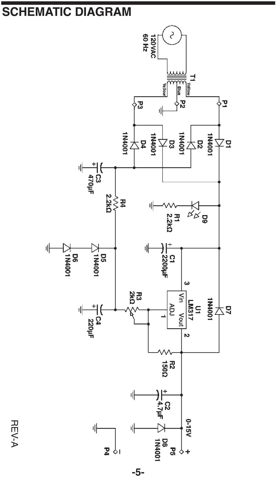
6 SCHEMATIC DIAGRAM REV-A -5-
7 PARTS LIST RESISTORS Qty. Symbol Description Part # r 1 R2 150W 5% 1/4W r 2 R1, R4 2.2kW 5% 1/4W r 1 R3 2kW Potentiometer CAPACITORS Qty. Symbol Description Part # r 1 C2 4.7mF 50V Electrolytic r 1 C4 220mF 16V Electrolytic r 1 C3 470mF 35V Electrolytic r 1 C1 2,200mF 35V Electrolytic SEMICONDUCTORS Qty. Symbol Description Part # r 8 D1-8 1N4001 Diode r 1 U1 LM317 Regulator r 1 D9 LED Red MISCELLANEOUS Qty. Symbol Part # r 1 Transformer YD r 1 PC board r 1 Heat sink r 1 Knob r 1 Case top r 1 Case bottom r 1 Strain relief 2-wire r 1 Binding post black r 2 Nut binding post HN r 2 Lockwasher binding post LW r 1 Binding post red r 4 Screw 3 x 8mm r 1 Screw 4-40 x 1/ r 2 Screw 6-32 x 3/8 Blk r 1 Nut 7mm r 1 Nut r 2 Nut r 1 Washer flat 8 x 14mm r 4 Washer fiber # r 2 Lockwasher # r 4 Rubber foot r 1 Label top r 1 Line cord 2 wire r 2 Shrink tubing

8 TWO YEAR WARRANTY All Elenco models are guaranteed for two full years on all parts and service. For the first 3 months, your power supply is covered at absolutely no charge. For the remaining 21 months, a nominal service charge is required to cover shipping and handling. When returning merchandise for repair, please include proof of purchase, a brief letter of explanation of problem, and sufficient packing material. Before returning any merchandise please call our service department at (847) to obtain a return authorization number (RMA). ELENCO 150 Carpenter Ave. Wheeling, IL (847) Website: elenco@elenco.com

TRANSISTOR/DIODE TESTER
 TRANSISTOR/DIODE TESTER MODEL DT-100 Lesson Manual ELENCO Copyright 2012, 1988 REV-G 753115 Elenco Electronics, Inc. Revised 2012 FEATURES Diode Mode: 1. Checks all types of diodes - germanium, silicon,
CONSTRUCTING A VARIABLE POWER SUPPLY UNIT
 CONSTRUCTING A VARIABLE POWER SUPPLY UNIT Building a power supply is a good way to put into practice many of the ideas we have been studying about electrical power so far. Most often, power supplies are
ECEN 1400, Introduction to Analog and Digital Electronics
 ECEN 1400, Introduction to Analog and Digital Electronics Lab 4: Power supply 1 INTRODUCTION This lab will span two lab periods. In this lab, you will create the power supply that transforms the AC wall
The full wave rectifier consists of two diodes and a resister as shown in Figure
 The Full-Wave Rectifier The full wave rectifier consists of two diodes and a resister as shown in Figure The transformer has a centre-tapped secondary winding. This secondary winding has a lead attached
Power Supplies. 1.0 Power Supply Basics. www.learnabout-electronics.org. Module
 Module 1 www.learnabout-electronics.org Power Supplies 1.0 Power Supply Basics What you ll learn in Module 1 Section 1.0 Power Supply Basics. Basic functions of a power supply. Safety aspects of working
ANADOLU UNIVERSITY DEPARTMENT OF ELECTRICAL AND ELECTRONICS ENGINEERING
 ANADOLU UNIVERSITY DEPARTMENT OF ELECTRICAL AND ELECTRONICS ENGINEERING EEM 102 INTRODUCTION TO ELECTRICAL ENGINEERING EXPERIMENT 9: DIODES AND DC POWER SUPPLY OBJECTIVE: To observe how a diode functions
Diode Applications. As we have already seen the diode can act as a switch Forward biased or reverse biased - On or Off.
 Diode Applications Diode Switching As we have already seen the diode can act as a switch Forward biased or reverse biased - On or Off. Voltage Rectifier A voltage rectifier is a circuit that converts an
Unit/Standard Number. High School Graduation Years 2010, 2011 and 2012
 1 Secondary Task List 100 SAFETY 101 Demonstrate an understanding of State and School safety regulations. 102 Practice safety techniques for electronics work. 103 Demonstrate an understanding of proper
X-ray Imaging System. X-Ray Circuit. Principles of Imaging Science II (RAD 120) X-ray Imaging System Circuitry
 X-ray Imaging System Circuitry") Principles of Imaging Science II (RAD 120) X-ray Imaging System Circuitry X-ray Imaging System Operating console Set x-ray tube current (quantity) and voltage (quality) Controls line compensation, kvp,
Principles of Imaging Science II (RAD 120) X-ray Imaging System Circuitry X-ray Imaging System Operating console Set x-ray tube current (quantity) and voltage (quality) Controls line compensation, kvp,
LM 358 Op Amp. If you have small signals and need a more useful reading we could amplify it using the op amp, this is commonly used in sensors.
 LM 358 Op Amp S k i l l L e v e l : I n t e r m e d i a t e OVERVIEW The LM 358 is a duel single supply operational amplifier. As it is a single supply it eliminates the need for a duel power supply, thus
electronics fundamentals
 electronics fundamentals circuits, devices, and applications THOMAS L. FLOYD DAVID M. BUCHLA Lesson 1: Diodes and Applications Center-Tapped Full-wave Rectifier The center-tapped (CT) full-wave rectifier
LM138 LM338 5-Amp Adjustable Regulators
 LM138 LM338 5-Amp Adjustable Regulators General Description The LM138 series of adjustable 3-terminal positive voltage regulators is capable of supplying in excess of 5A over a 1 2V to 32V output range
Yrd. Doç. Dr. Aytaç Gören
 H2 - AC to DC Yrd. Doç. Dr. Aytaç Gören ELK 2018 - Contents W01 Basic Concepts in Electronics W02 AC to DC Conversion W03 Analysis of DC Circuits W04 Transistors and Applications (H-Bridge) W05 Op Amps
GLOLAB Two Wire Stepper Motor Positioner
 Introduction A simple and inexpensive way to remotely rotate a display or object is with a positioner that uses a stepper motor to rotate it. The motor is driven by a circuit mounted near the motor and
AC Direct Off-Line Power Supplies
 AC Direct Off-Line Power Supplies r Introduction Many DC power supplies found in electronic systems, including those in this Tech School, rectify the 120 volts available at an electric outlet. The initial
LM117 LM317A LM317 3-Terminal Adjustable Regulator
 LM117 LM317A LM317 3-Terminal Adjustable Regulator General Description The LM117 series of adjustable 3-terminal positive voltage regulators is capable of supplying in excess of 1 5A over a 1 2V to 37V
THE MclNTOSH MC 2100 SOLID STATE STEREO POWER AMPLIFIER
 THE MclNTOSH MC 2100 SOLID STATE STEREO POWER AMPLIFIER Price $1.25 Your MC 2100 stereo amplifier will give you many years of pleasant and satisfactory performance. If you have any questions concerning
Type SA-1 Generator Differential Relay
 ABB Automation Inc. Substation Automation and Protection Division Coral Springs, FL 33065 Instruction Leaflet 41-348.11C Effective: November 1999 Supersedes I.L. 41-348.11B, Dated August 1986 ( ) Denotes
Lecture - 4 Diode Rectifier Circuits
 Basic Electronics (Module 1 Semiconductor Diodes) Dr. Chitralekha Mahanta Department of Electronics and Communication Engineering Indian Institute of Technology, Guwahati Lecture - 4 Diode Rectifier Circuits
GLOLAB Universal Telephone Hold
 GLOLAB Universal Telephone Hold 1 UNIVERSAL HOLD CIRCUIT If you have touch tone telephone service, you can now put a call on hold from any phone in the house, even from cordless phones and phones without
6.101 Final Project Report Class G Audio Amplifier
 6.101 Final Project Report Class G Audio Amplifier Mark Spatz 4/3/2014 1 1 Introduction For my final project, I designed and built a 150 Watt audio amplifier to replace the underpowered and unreliable
Diodes and Transistors
 Diodes What do we use diodes for? Diodes and Transistors protect circuits by limiting the voltage (clipping and clamping) turn AC into DC (voltage rectifier) voltage multipliers (e.g. double input voltage)
Properties of electrical signals
 DC Voltage Component (Average voltage) Properties of electrical signals v(t) = V DC + v ac (t) V DC is the voltage value displayed on a DC voltmeter Triangular waveform DC component Half-wave rectifier
Kit 106. 50 Watt Audio Amplifier
 Kit 106 50 Watt Audio Amplifier T his kit is based on an amazing IC amplifier module from ST Electronics, the TDA7294 It is intended for use as a high quality audio class AB amplifier in hi-fi applications
DIODE CIRCUITS LABORATORY. Fig. 8.1a Fig 8.1b
 DIODE CIRCUITS LABORATORY A solid state diode consists of a junction of either dissimilar semiconductors (pn junction diode) or a metal and a semiconductor (Schottky barrier diode). Regardless of the type,
The D.C Power Supply
 The D.C Power Supply Voltage Step Down Electrical Isolation Converts Bipolar signal to Unipolar Half or Full wave Smoothes the voltage variation Still has some ripples Reduce ripples Stabilize the output
EET272 Worksheet Week 9
 EET272 Worksheet Week 9 answer questions 1-5 in preparation for discussion for the quiz on Monday. Finish the rest of the questions for discussion in class on Wednesday. Question 1 Questions AC s are becoming
Transistor Characteristics and Single Transistor Amplifier Sept. 8, 1997
 Physics 623 Transistor Characteristics and Single Transistor Amplifier Sept. 8, 1997 1 Purpose To measure and understand the common emitter transistor characteristic curves. To use the base current gain
Precision Diode Rectifiers
 by Kenneth A. Kuhn March 21, 2013 Precision half-wave rectifiers An operational amplifier can be used to linearize a non-linear function such as the transfer function of a semiconductor diode. The classic
= V peak 2 = 0.707V peak
 BASIC ELECTRONICS - RECTIFICATION AND FILTERING PURPOSE Suppose that you wanted to build a simple DC electronic power supply, which operated off of an AC input (e.g., something you might plug into a standard
AP-1 Application Note on Remote Control of UltraVolt HVPS
 Basics Of UltraVolt HVPS Output Voltage Control Application Note on Remote Control of UltraVolt HVPS By varying the voltage at the Remote Adjust Input terminal (pin 6) between 0 and +5V, the UV highvoltage
Fundamentals of Signature Analysis
 Fundamentals of Signature Analysis An In-depth Overview of Power-off Testing Using Analog Signature Analysis www.huntron.com 1 www.huntron.com 2 Table of Contents SECTION 1. INTRODUCTION... 7 PURPOSE...
Rectifier circuits & DC power supplies
 Rectifier circuits & DC power supplies Goal: Generate the DC voltages needed for most electronics starting with the AC power that comes through the power line? 120 V RMS f = 60 Hz T = 1667 ms) = )sin How
Electronics. Discrete assembly of an operational amplifier as a transistor circuit. LD Physics Leaflets P4.2.1.1
 Electronics Operational Amplifier Internal design of an operational amplifier LD Physics Leaflets Discrete assembly of an operational amplifier as a transistor circuit P4.2.1.1 Objects of the experiment
Analog & Digital Electronics Course No: PH-218
 Analog & Digital Electronics Course No: PH-18 Lec 3: Rectifier and Clipper circuits Course nstructors: Dr. A. P. VAJPEY Department of Physics, ndian nstitute of Technology Guwahati, ndia 1 Rectifier Circuits:
Transformer circuit calculations
 Transformer circuit calculations This worksheet and all related files are licensed under the Creative Commons Attribution License, version 1.0. To view a copy of this license, visit http://creativecommons.org/licenses/by/1.0/,
Diode Applications. by Kenneth A. Kuhn Sept. 1, 2008. This note illustrates some common applications of diodes.
 by Kenneth A. Kuhn Sept. 1, 2008 This note illustrates some common applications of diodes. Power supply applications A common application for diodes is converting AC to DC. Although half-wave rectification
Operating Manual Ver.1.1
 Class B Amplifier (Push-Pull Emitter Follower) Operating Manual Ver.1.1 An ISO 9001 : 2000 company 94-101, Electronic Complex Pardesipura, Indore- 452010, India Tel : 91-731- 2570301/02, 4211100 Fax: 91-731-
LM78XX Series Voltage Regulators
 LM78XX Series Voltage Regulators General Description Connection Diagrams The LM78XX series of three terminal regulators is available with several fixed output voltages making them useful in a wide range
GenTech Practice Questions
 GenTech Practice Questions Basic Electronics Test: This test will assess your knowledge of and ability to apply the principles of Basic Electronics. This test is comprised of 90 questions in the following
Physics 623 Transistor Characteristics and Single Transistor Amplifier Sept. 13, 2006
 Physics 623 Transistor Characteristics and Single Transistor Amplifier Sept. 13, 2006 1 Purpose To measure and understand the common emitter transistor characteristic curves. To use the base current gain
Building the HVPS High Voltage Power Supply
 Introduction Building the HVPS High Voltage Power Supply Voltages higher than the LVPS provides kilovolts are needed in later experiments to get strong electric fields and to generate microwaves. The high-voltage
Power Management & Supply. Design Note. Version 1.0, Nov. 2001 DN-EVALMF2ICE2A265-1. CoolSET 35W DVD Power Supply with ICE2A265.
 Version 1.0, Nov. 2001 Design Note DN-EVALMF2ICE2A265-1 CoolSET 35W DVD Power Supply with ICE2A265 Author: Harald Zöllinger Published by Infineon Technologies AG http://www.infineon.com Power Management
Semiconductor Diode. It has already been discussed in the previous chapter that a pn junction conducts current easily. Principles of Electronics
 76 6 Principles of Electronics Semiconductor Diode 6.1 Semiconductor Diode 6.3 Resistance of Crystal Diode 6.5 Crystal Diode Equivalent Circuits 6.7 Crystal Diode Rectifiers 6.9 Output Frequency of Half-Wave
LABORATORY 10 TIME AVERAGES, RMS VALUES AND THE BRIDGE RECTIFIER. Bridge Rectifier
 LABORATORY 10 TIME AVERAGES, RMS VALUES AND THE BRIDGE RECTIFIER Full-wave Rectification: Bridge Rectifier For many electronic circuits, DC supply voltages are required but only AC voltages are available.
Series AMLDL-Z Up to 1000mA LED Driver
 FEATURES: Click on Series name for product info on aimtec.com Series Up to ma LED Driver Models Single output Model Input Voltage (V) Step Down DC/DC LED driver Operating Temperature range 4ºC to 85ºC
High voltage power supply (1 to 20 KV)
") High voltage power supply ( to 0 KV) Ammar Ahmed Khan, Muhammad Wasif, Muhammad Sabieh Anwar This documentation is divided into two parts, the first part provides a brief overview about the key features
High voltage power supply ( to 0 KV) Ammar Ahmed Khan, Muhammad Wasif, Muhammad Sabieh Anwar This documentation is divided into two parts, the first part provides a brief overview about the key features
13. Diode Rectifiers, Filters, and Power Supplies
 1 13. Diode Rectifiers, Filters, and Power Supplies Introduction A power supply takes Alternating Current or A.C. power from your electric utility (Con Edison) and converts the A.C. electrical current
TDA4605 CONTROL CIRCUIT FOR SWITCH MODE POWER SUPPLIES USING MOS TRANSISTORS
 CONTROL CIRCUIT FOR SWITCH MODE POWER SUPPLIES USING MOS TRANSISTORS Fold-Back Characteristic provides Overload Protection for External Diodes Burst Operation under Short-Circuit and no Load Conditions
LM350. 3.0 A, Adjustable Output, Positive Voltage Regulator THREE TERMINAL ADJUSTABLE POSITIVE VOLTAGE REGULATOR
 3. A, able Output, Positive Voltage Regulator The is an adjustable threeterminal positive voltage regulator capable of supplying in excess of 3. A over an output voltage range of 1.2 V to 33 V. This voltage
CHAPTER 2B: DIODE AND APPLICATIONS. D.Wilcher
 CHAPTER 2B: DIODE AND APPLICATIONS D.Wilcher 1 CHAPTER 2B: OBJECTIVES Analyze the operation of 3 basic types of rectifiers Describe the operation of rectifier filters and IC regulators Analyze the operation
SYMMETRIC 1A POWER SUPPLY K8042
 SYMMETRIC 1A POWER SUPPLY K8042 Low cost universal symmetric power supply ILLUSTRATED ASSEMBLY MANUAL H8042IP-1 Features & Specifications Features low cost universal symmetric power supply just add a suitable
Regulated D.C. Power Supply
 442 17 Principles of Electronics Regulated D.C. Power Supply 17.1 Ordinary D.C. Power Supply 17.2 Important Terms 17.3 Regulated Power Supply 17.4 Types of Voltage Regulators 17.5 Zener Diode Voltage Regulator
Diode Circuits. Operating in the Reverse Breakdown region. (Zener Diode)
") Diode Circuits Operating in the Reverse Breakdown region. (Zener Diode) In may applications, operation in the reverse breakdown region is highly desirable. The reverse breakdown voltage is relatively insensitive
Diode Circuits Operating in the Reverse Breakdown region. (Zener Diode) In may applications, operation in the reverse breakdown region is highly desirable. The reverse breakdown voltage is relatively insensitive
Charger Output AC Ripple Voltage and the affect on VRLA batteries
 TECHNICAL BULLETIN 41-2131 Charger Output AC Ripple Voltage and the affect on VRLA batteries Please Note: The information in this technical bulletin was developed for C&D Dynasty 12 Volt VRLA products.
Content Map For Career & Technology
 Content Strand: Applied Academics CT-ET1-1 analysis of electronic A. Fractions and decimals B. Powers of 10 and engineering notation C. Formula based problem solutions D. Powers and roots E. Linear equations
Transistor Amplifiers
 Physics 3330 Experiment #7 Fall 1999 Transistor Amplifiers Purpose The aim of this experiment is to develop a bipolar transistor amplifier with a voltage gain of minus 25. The amplifier must accept input
Total solder points: 57 Difficulty level: beginner 1 2 3 4 5 advanced 3 TO 30VDC / 3A POWER SUPPLY K7203 ILLUSTRATED ASSEMBLY MANUAL H7203IP-1
 Total solder points: 57 Difficulty level: beginner 1 2 3 4 5 advanced 3 TO 30VDC / 3A POWER SUPPLY K7203 A power supply for all our kits, based on a stabilised DC voltage of 30V. ILLUSTRATED ASSEMBLY MANUAL
BSNL TTA Question Paper-Instruments and Measurement Specialization 2007
 BSNL TTA Question Paper-Instruments and Measurement Specialization 2007 (1) Instrument is a device for determining (a) the magnitude of a quantity (b) the physics of a variable (c) either of the above
ULRASONIC GENERATOR POWER CIRCUITRY. Will it fit on PC board
 ULRASONIC GENERATOR POWER CIRCUITRY Will it fit on PC board MAJOR COMPONENTS HIGH POWER FACTOR RECTIFIER RECTIFIES POWER LINE RAIL SUPPLY SETS VOLTAGE AMPLITUDE INVERTER INVERTS RAIL VOLTAGE FILTER FILTERS
Chapter 2 MENJANA MINDA KREATIF DAN INOVATIF
 Chapter 2 DIODE part 2 MENJANA MINDA KREATIF DAN INOATIF objectives Diode with DC supply circuit analysis serial & parallel Diode d applications the DC power supply & Clipper Analysis & Design of rectifier
LM1084 5A Low Dropout Positive Regulators
 5A Low Dropout Positive Regulators General Description The LM1084 is a series of low dropout voltage positive regulators with a maximum dropout of 1.5 at 5A of load current. It has the same pin-out as
Chapter 3. Diodes and Applications. Introduction [5], [6]
![Chapter 3. Diodes and Applications. Introduction [5], [6]](/thumbs/40/21801962.jpg "Chapter 3. Diodes and Applications. Introduction [5], [6]") Chapter 3 Diodes and Applications Introduction [5], [6] Diode is the most basic of semiconductor device. It should be noted that the term of diode refers to the basic p-n junction diode. All other diode
Chapter 3 Diodes and Applications Introduction [5], [6] Diode is the most basic of semiconductor device. It should be noted that the term of diode refers to the basic p-n junction diode. All other diode
Study Guide for the Electronics Technician Pre-Employment Examination
 Bay Area Rapid Transit District Study Guide for the Electronics Technician Pre-Employment Examination INTRODUCTION The Bay Area Rapid Transit (BART) District makes extensive use of electronics technology
LEP 4.4.07. Rectifier circuits
 Related topics Half-wave rectifier, full-wave rectifier, Graetz rectifier, diode, Zener diode, avalanche effect, charging capacitor, ripple, r.m.s. value, internal resistance, smoothing factor, ripple
Theory of Transistors and Other Semiconductor Devices
 Theory of Transistors and Other Semiconductor Devices 1. SEMICONDUCTORS 1.1. Metals and insulators 1.1.1. Conduction in metals Metals are filled with electrons. Many of these, typically one or two per
Experiment 2 Diode Applications: Rectifiers
 ECE 3550 - Practicum Fall 2007 Experiment 2 Diode Applications: Rectifiers Objectives 1. To investigate the characteristics of half-wave and full-wave rectifier circuits. 2. To recognize the usefulness
Objectives: Part 1: Build a simple power supply. CS99S Laboratory 1
 CS99S Laboratory 1 Objectives: 1. Become familiar with the breadboard 2. Build a logic power supply 3. Use switches to make 1s and 0s 4. Use LEDs to observe 1s and 0s 5. Make a simple oscillator 6. Use
L78. Positive voltage regulator ICs. Description. Features
 Positive voltage regulator ICs Description Datasheet - production data TO-220 Features DPAK TO-220FP D²PAK Output current up to 1.5 A Output voltages of 5; 6; 8; 8.5; 9; 12; 15; 18; 24 V Thermal overload
LM2576R. 3.0A, 52kHz, Step-Down Switching Regulator FEATURES. Applications DESCRIPTION TO-220 PKG TO-220V PKG TO-263 PKG ORDERING INFORMATION
 LM2576 FEATURES 3.3, 5.0, 12, 15, and Adjustable Output ersions Adjustable ersion Output oltage Range, 1.23 to 37 +/- 4% AG10Maximum Over Line and Load Conditions Guaranteed 3.0A Output Current Wide Input
Module 11: Conducted Emissions
 Module 11: Conducted Emissions 11.1 Overview The term conducted emissions refers to the mechanism that enables electromagnetic energy to be created in an electronic device and coupled to its AC power cord.
Seven function digital multimeter
 Seven function digital multimeter 98025 Set up And Operating Instructions Distributed exclusively by Harbor Freight Tools. 3491 Mission Oaks Blvd., Camarillo, CA 93011 Visit our website at: http://www.harborfreight.com
7-41 POWER FACTOR CORRECTION
 POWER FTOR CORRECTION INTRODUCTION Modern electronic equipment can create noise that will cause problems with other equipment on the same supply system. To reduce system disturbances it is therefore essential
L78MxxAB L78MxxAC. Precision 500 ma regulators. Features. Description
 L78MxxAB L78MxxAC Precision 500 ma regulators Features Output current to 0.5 A Output voltages of 5; 6; 8; 9; 10; 12; 15; 18; 24 V Thermal overload protection Short circuit protection Output transition
LM134-LM234-LM334. Three terminal adjustable current sources. Features. Description
 Three terminal adjustable current sources Features Operates from 1V to 40V 0.02%/V current regulation Programmable from 1µA to 10mA ±3% initial accuracy Description The LM134/LM234/LM334 are 3-terminal
Talon VFD / Inverter Meter
 Talon VFD / Inverter Meter Patent Pending. Copyright 2009. Page 1 of 37 Table of Contents Talon VFD/Inverter meter... 1 Table of Contents... 2 WARNING...3 Product Summary... 4 Product Cautions and Theory
Joule Thief 3.0 Kit. June 2012, Rev 1 1 http://www.easternvoltageresearch.com Joule Thief 3.0
 Kit Instruction Manual Eastern Voltage Research, LLC June 2012, Rev 1 1 http://www.easternvoltageresearch.com HIGH BRIGHTNESS LED THIS KIT USES A 1W CREE, HIGH BRIGHTNESS LED. DO NOT STARE AT THIS (OR
BLWR23MDA Series. 24V, 15A Brushless Controller / Motor. User s Guide. 910 East Orangefair Lane, Anaheim, CA 92801 e-mail: info@anaheimautomation.
 BLWR23MDA Series 24V, 15A Brushless Controller / Motor User s Guide A N A H E I M A U T O M A T I O N 910 East Orangefair Lane, Anaheim, CA 92801 e-mail: info@anaheimautomation.com (714) 992-6990 fax:
LM79XX Series 3-Terminal Negative Regulators
 LM79XX Series 3-Terminal Negative Regulators General Description The LM79XX series of 3-terminal regulators is available with fixed output voltages of b5v b8v b12v and b15v These devices need only one
CAT AVR V2.3. Instruction Manual. Voltage regulator for generators. March 2008
 CAT AVR V2.3 Voltage regulator for generators March 2008 Instruction Manual Warnings WARNING The system should not be installed, operated, serviced or modified except by qualified personnel who understand
Programmable Single-/Dual-/Triple- Tone Gong SAE 800
 Programmable Single-/Dual-/Triple- Tone Gong Preliminary Data SAE 800 Bipolar IC Features Supply voltage range 2.8 V to 18 V Few external components (no electrolytic capacitor) 1 tone, 2 tones, 3 tones
BURGLAR ALARM KIT MODEL K-23. Assembly and Instruction Manual ELENCO
 BURGLAR ALARM KIT MODEL K-23 Assembly and Instruction Manual ELENCO Copyright 2013, 1989 ELENCO Electronics, Inc. Revised 2011 REV-Q 753223 No part of this book shall be reproduced by any means; electronic,
Lab 3 Rectifier Circuits
 ECET 242 Electronic Circuits Lab 3 Rectifier Circuits Page 1 of 5 Name: Objective: Students successfully completing this lab exercise will accomplish the following objectives: 1. Learn how to construct
Troubleshooting And Repairing ATX Power Supply
 Troubleshooting And Repairing ATX Power Supply Brought to you by Jestine Yong Http://www.PowerSupplyRepairGuide.com I hope that you have enjoyed the short report of The Easy Way To Understand Switch Mode
Silicon Controlled Rectifiers
 554 20 Principles of Electronics Silicon Controlled Rectifiers 20.1 Silicon Controlled Rectifier (SCR) 20.2 Working of SCR 20.3 Equivalent Circuit of SCR 20.4 Important Terms 20.5 V-I Characteristics of
Chapter 19 Operational Amplifiers
 Chapter 19 Operational Amplifiers The operational amplifier, or op-amp, is a basic building block of modern electronics. Op-amps date back to the early days of vacuum tubes, but they only became common
Efficient and reliable operation of LED lighting is dependent on the right choice of current-limiting resistor
 Efficient and reliable operation of LED lighting is dependent on the right choice of current-limiting resistor Phil Ebbert, VP of Engineering, Riedon Inc. Introduction Not all resistors are the same and
RESISTANCE SUBSTITUTION BOX
 RESISTANCE SUBSTITUTION BOX MODEL RS-400 / K-37 Assembly and Instruction Manual TM Elenco Electronics, Inc. Copyright 1990 Elenco TM Electronics, Inc. Revised 2003 REV-G 753RS400 The Resistance Substitution
Cumbria Designs T-1. SSB/CW Filter kit (4.9152MHz) User Manual
 User Manual") Cumbria Designs T-1 SSB/CW Filter kit (4.9152MHz) User Manual CONTENTS 1 INTRODUCTION 2 2 CIRCUIT DESCRIPTION 2 3 ASSEMBLY 2 4 TESTING 4 The Steading Stainton PENRITH Cumbria CA11 0ES UK 1 Introduction
Cumbria Designs T-1 SSB/CW Filter kit (4.9152MHz) User Manual CONTENTS 1 INTRODUCTION 2 2 CIRCUIT DESCRIPTION 2 3 ASSEMBLY 2 4 TESTING 4 The Steading Stainton PENRITH Cumbria CA11 0ES UK 1 Introduction
7 FUNCTION DIGITAL MULTIMETER
 7 FUNCTION DIGITAL MULTIMETER 90899 OPERATING INSTRUCTIONS 3491 Mission Oaks Blvd., Camarillo, CA 93011 Visit our Web site at http://www.harborfreight.com Copyright 2004 by Harbor Freight Tools. All rights
Example of use: Fuse for a solenoid valve. If the fuse is defective, no information is sent to the electronic component.
 Overview Switch and button modules The dimensions of the switch and button modules are adapted to the electronic components in the integral housing. The modules are equipped with the universal clip-on
New High Current MOSFET Module Offers 177 µω R DS(on)
") ew High Current Offers 177 µω R D(on) By William C. Kephart, Eric R. Motto Application Engineering owerex Incorporated Abstract This paper describes a new family of high current modules optimized for industrial
ew High Current Offers 177 µω R D(on) By William C. Kephart, Eric R. Motto Application Engineering owerex Incorporated Abstract This paper describes a new family of high current modules optimized for industrial
What is a multimeter?
 What is a multimeter? A multimeter is a devise used to measure voltage, resistance and current in electronics & electrical equipment It is also used to test continuity between to 2 points to verify if
Building the AMP Amplifier
 Building the AMP Amplifier Introduction For about 80 years it has been possible to amplify voltage differences and to increase the associated power, first with vacuum tubes using electrons from a hot filament;
Description. Table 1. Device summary
 2 A positive voltage regulator IC Description Datasheet - production data Features TO-220 Output current up to 2 A Output voltages of 5; 7.5; 9; 10; 12; 15; 18; 24 V Thermal protection Short circuit protection
Without the pre amp, these microphones sound very good with tube equipment that provided a very high impedance load to the element.
 N9WB D-104 Project Revision 2 Pre Amp Modifications for higher load impedance. By Walter A. Breining, N9WB D-104 Discussion The D-104 has been around since the 30 s and is still popular today for communications.
SWITCH-MODE POWER SUPPLY CONTROLLER PULSE OUTPUT DC OUTPUT GROUND EXTERNAL FUNCTION SIMULATION ZERO CROSSING INPUT CONTROL EXTERNAL FUNCTION
 SWITCH-MODE POWER SUPPLY CONTROLLER. LOW START-UP CURRENT. DIRECT CONTROL OF SWITCHING TRAN- SISTOR. COLLECTOR CURRENT PROPORTIONAL TO BASE-CURRENT INPUT REERSE-GOING LINEAR OERLOAD CHARACTERISTIC CURE
TDA2040. 20W Hi-Fi AUDIO POWER AMPLIFIER
 20W Hi-Fi AUDIO POWER AMPLIFIER DESCRIPTION The TDA2040 is a monolithic integrated circuit in Pentawatt package, intended for use as an audio class AB amplifier. Typically it provides 22W output power
6.101 Final Project Proposal Class G Audio Amplifier. Mark Spatz
 6.101 Final Project Proposal Class G Audio Amplifier Mark Spatz 1 1 Introduction For my final project, I will be constructing a 30V audio amplifier capable of delivering about 150 watts into a network
Panasonic Microwave Oven Inverter HV Power Supply
 Panasonic Microwave Oven Inverter HV Power Supply David Smith VK3HZ (vk3hz (*at*) wia.org.au) This particular power supply comes from a circa-2000 Panasonic Microwave model NN-S550WF. Nearly all Panasonic