Yrd. Doç. Dr. Aytaç Gören
|
|
|
- Mark Johnston
- 8 years ago
- Views:
Transcription
1 H2 - AC to DC Yrd. Doç. Dr. Aytaç Gören

2 ELK Contents W01 Basic Concepts in Electronics W02 AC to DC Conversion W03 Analysis of DC Circuits W04 Transistors and Applications (H-Bridge) W05 Op Amps and Applications W06 Sensors and Measurement (1/2) W07 Sensors and Measurement (2/2) W08 Midterm W09 Basic Concepts in Digital Electronics (Boolean Algebra, Decimal to binary, gates) W10 Digital Logic Circuits (Gates and Flip Flops) W11 PLC s W12 Microprocessors W13 Data Acquisition, D/A and A/D Converters. 2
 W10 Digital Logic Circuits (Gates and Flip Flops) W11 PLC s W12 Microprocessors W13 Data Acquisition, D/A and")
3 ELK 2018 W01 Contents 1. AC Form and values of grid 2. Potentiometer 3. Transformers 4. Semi Conductors 5. Diodes 6. Conversion to DC 1. Half Wave Rectifier 2. Half Wave Rectifier with Smoothing Capacitor 3. Using full wave rectifier 4. Using diode bridge rectifier Voltage Regulator IC 8. Switch Mode Power Supply Selection 3


4 Why conversion? Electricity is transferred from power plants to houses or business as alternate current because of decreasing losses during transfer. On the other hand, semi conductors use direct current. Thus, it is needed to be changed to direct current. A rectifier is a circuit which converts the Alternating Current (AC) input power into a Direct Current (DC) output power. Yrd. Doç. Dr. Aytaç Gören


5 Yrd. Doç. Dr. Aytaç Gören Potentiometer

6 Potentiometer Yrd. Doç. Dr. Aytaç Gören

7 Transformers Ref: 7 Yrd. Doç. Dr. Aytaç Gören


8 Transformers K trafo N N S P V V S P I I P S 8 Ref: Yrd. Doç. Dr. Aytaç Gören

9 Semi Conductors Semiconductors materials such as silicon (Si), germanium (Ge) and gallium arsenide (GaAs), have electrical properties somewhere in the middle, between those of a "conductor" and an "insulator". They are not good conductors nor good insulators (hence their name "semi"-conductors). They have very few "fee electrons" because their atoms are closely grouped. That is due to the strength of the molecular bounds However, their ability to conduct electricity can be greatly improved by adding certain "impurities" to this crystalline structure thereby, producing more free electrons than holes 9


10 Semi Conductors The most commonly used semiconductor basics material by far is silicon. Its atomic number is 14 Silicon has four valence electrons in its outermost shell Semiconductors- Silicon The structure of the bond between the two silicon atoms is such that each atom shares one electron with its neighbour This bound is very stable and called as co valent bound crystals of pure silicon (or germanium) are therefore good insulators. 10
 are")

11 Semi Conductors Semiconductor N-type In order for our silicon crystal to conduct electricity, we need to introduce an impurity atom such as Arsenic, Antimony or Phosphorus These atoms have five outer electrons in their outermost orbital to share with neighbouring atoms. This allows four out of the five orbital electrons to bond with its neighbouring silicon atoms leaving one "free electron" to become mobile when an electrical voltage is applied. The resulting semiconductor material has extra electrons, each with a negative charge, and is therefore referred to as an "N-type" material 11


12 Semi Conductors Another way to make silicon crystal conduct electricity is to add impurity atoms such as Aluminium, Boron or Indium, which have only three valence electrons Semiconductor P-Type Therefore, a complete connection is not possible, giving the semiconductor material an abundance of positively charged carriers known as "holes" in the structure of the crystal where electrons are effectively missing. The doping of such atoms causes conduction to consist mainly of positive charge carriers resulting in a "Ptype" material with the positive holes 12

13 Semi Conductors Semiconductor PN Junction These semiconductor N and P-type materials do very little on their own as they are electrically neutral, but when we join (or fuse) them together these two materials behave in a very different way producing what is generally known as a PN Junction. When the N and P-type semiconductor materials are first joined together a diffuusion phenomena occurs. The free electrons from the N-type impurity atoms begin to migrate across this newly formed junction to fill up the holes in the P-type material 13


14 Semi Conductors This process continues back and forth until the number of electrons which have crossed the junction have a large enough electrical charge to repel or prevent any more carriers from crossing the junction. Eventually a state of equilibrium (electrically neutral situation) will occur producing a "potential barrier" zone around the area of the junction This area around the junction is now called the Depletion Layer.(gerilim seti) This layer produces a potential difference vallue of for silicon about volts and for germanium about volts. This potential barrier will always exist even if the device is not connected to any external power source. Semiconductor PN Junction 14
 This layer produces a potential difference vallue of for silicon about 0.6-0.7 volts and for germanium about 0.3-0.35 volts.")

15 Semi Conductors However, if we were to make electrical connections at the ends of both the N-type and the P-type materials and then connect them to a battery source.this additional energy source overcomes the barrier resulting in free charges being able to cross the depletion region from one side to the other. The behavior of the PN junction with regards to the potential barrier width produces an asymmetrical conducting two terminal device, better known as the Junction Diode. A diode is one of the simplest semiconductor devices, which has the characteristic of passing current in one direction only However, unlike a resistor, a diode does not behave linearly with respect to the applied voltage as the diode has an exponential I-V relationship PN Junction Diode 15


16 Semi Conductors There are two operating regions for a diode: Forward biased and Reverse biased. Operation of a Diode When a diode is connected in a Reverse Bias condition, a positive voltage is applied to the N-type material and a negative voltage is applied to the P-type material. When a diode is connected in a Forward Bias condition, a negative voltage is applied to the N-type material and a positive voltage is applied to the P-type material. 16

17 Diodes 17
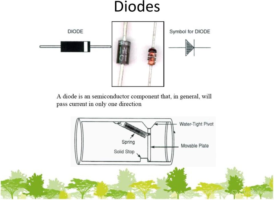
18 Diodes (open door/closed door) 18

19 Diodes (more ) Leds are also diodes which emit light. 19

20 Ref: 20 Yrd. Doç. Dr. Aytaç Gören Diodes The power semiconductor diode, known simply as the Power Diode, has a much larger PN junction area compared to its smaller signal diode cousin, resulting in a high forward current capability of up to several hundred amps (KA) and a reverse blocking voltage of up to several thousand volts (KV). Since the power diode has a large PN junction, it is not suitable for high frequency applications above 1MHz, but special and expensive high frequency, high current diodes are available. For high frequency rectifier applications Schottky Diodes are generally used because of their short reverse recovery time and low voltage drop in their forward bias condition.

21 Diodes If an alternating voltage is applied across a power diode, during the positive half cycle the diode will conduct passing current and during the negative half cycle the diode will not conduct blocking the flow of current. Then conduction through the power diode only occurs during the positive half cycle and is therefore unidirectional i.e. DC as shown. 21
22 Half Wave Rectifier Power diodes can be used individually as above or connected together to produce a variety of rectifier circuits such as "Half- Wave", "Full-Wave" or as "Bridge Rectifiers". The input power supply may be either a single-phase or a multiphase supply with the simplest of all the rectifier circuits being that of the Half Wave Rectifier. The power diode in a half wave rectifier circuit passes just one half of each complete sine wave of the AC supply in order to convert it into a DC supply. Then this type of circuit is called a "half-wave" rectifier because it passes only half of the incoming AC power supply. Ref: Yrd. Doç. Dr. Aytaç Gören
23 Half Wave Rectifier During each "positive" half cycle of the AC sine wave, the diode is forward biased as the anode is positive with respect to the cathode resulting in current flowing through the diode. Since the DC load is resistive (resistor, R), the current flowing in the load resistor is therefore proportional to the voltage (Ohm s Law), and the voltage across the load resistor will therefore be the same as the supply voltage,vs (minus Vf), that is the "DC" voltage across the load is sinusoidal for the first half cycle only sovout = Vs. Ref: Yrd. Doç. Dr. Aytaç Gören

24 Half Wave Rectifier During each "negative" half cycle of the AC sine wave, the diode is reverse biased as the anode is negative with respect to the cathode therefore, No current flows through the diode or circuit. Then in the negative half cycle of the supply, no current flows in the load resistor as no voltage appears across it sovout = 0. Ref: Yrd. Doç. Dr. Aytaç Gören
25 Half Wave Rectifier The current on the DC side of the circuit flows in one direction only making the circuit Unidirectional and the value of the DC voltage V DC across the load resistor is calculated as follows. Where V max is the maximum voltage value of the AC supply, and V S is the r.m.s. value of the supply. Ref: Yrd. Doç. Dr. Aytaç Gören

26 Half Wave Rectifier with Smoothing Capacitor When rectification is used to provide a direct voltage power supply from an alternating source, the amount of ripple can be further reduced by using larger value capacitors but there are limits both on cost and size. For a given capacitor value, a greater load current (smaller load resistor) will discharge the capacitor more quickly (RC Time Constant) and so increases the ripple obtained. Then for single phase, half-wave rectifier circuits it is not very practical to try and reduce the ripple voltage by capacitor smoothing alone, it is more practical to use "Full-wave Rectification" instead. Ref: Yrd. Doç. Dr. Aytaç Gören
27 Full Wave Rectifier In a Full Wave Rectifier circuit, two diodes are used, one for each half of the cycle. A transformer is used whose secondary winding is split equally into two halves with a common centre tapped connection, (C). This configuration results in each diode conducting in turn when its anode terminal is positive with respect to the transformer centre point C producing an output during both half-cycles, twice that for the half wave rectifier so it is 100% efficient. Ref: Yrd. Doç. Dr. Aytaç Gören
28 Full Wave Rectifier The full wave rectifier circuit consists of two power diodes connected to a single load resistance (R L ) with each diode taking it in turn to supply current to the load. When point A of the transformer is positive with respect to point C, diode D 1 conducts in the forward direction as indicated by the arrows. When point B is positive (in the negative half of the cycle) with respect to point C, diode D 2 conducts in the forward direction and the current flowing through resistor R is in the same direction for both half-cycles. As the output voltage across the resistor R is the phasor sum of the two waveforms combined, this type of full wave rectifier circuit is also known as a "bi-phase" circuit. Ref: Yrd. Doç. Dr. Aytaç Gören
29 Full Wave Rectifier As the spaces between each halfwave developed by each diode is now being filled in by the other diode the average DC output voltage across the load resistor is now double that of the single halfwave rectifier circuit and is about 0.637V max of the peak voltage, assuming no losses. Ref: Yrd. Doç. Dr. Aytaç Gören
30 Yrd. Doç. Dr. Aytaç Gören Using Diode Bridge Rectifier Another type of circuit that produces the same output waveform as the full wave rectifier circuit is that of the Full Wave Bridge Rectifier. This type of single phase rectifier uses four individual rectifying diodes connected in a closed loop "bridge" configuration to produce the desired output. The main advantage of this bridge circuit is that it does not require a special centre tapped transformer, thereby reducing its size and cost. The single secondary winding is connected to one side of the diode bridge network and the load to the other side.
31 Using Diode Bridge Rectifier The four diodes labelled D 1 to D 4 are arranged in "series pairs" with only two diodes conducting current during each half cycle. During the positive half cycle of the supply, diodes D1 and D2 conduct in series while diodes D3 and D4 are reverse biased and the current flows through the load as shown above. 31
32 Using Diode Bridge Rectifier As the current flowing through the load is unidirectional, so the voltage developed across the load is also unidirectional the same as for the previous two diode full-wave rectifier, therefore the average DC voltage across the load is 0.637V max. However in reality, during each half cycle the current flows through two diodes instead of just one so the amplitude of the output voltage is two voltage drops ( 2 x 0.7 = 1.4V ) less than the input V MAX amplitude. The ripple frequency is now twice the supply frequency (e.g. 100Hz for a 50Hz supply)

33 Typical Diode Bridge Rectifier
34 Using Diode Bridge Rectifier with Smoothing Capacitor The smoothing capacitor converts the full-wave rippled output of the rectifier into a smooth DC output voltage. Generally for DC power supply circuits the smoothing capacitor is an Aluminium Electrolytic type that has a capacitance value of 100uF or more with repeated DC voltage pulses from the rectifier charging up the capacitor to peak voltage. However, there are two important parameters to consider when choosing a suitable smoothing capacitor and these are its Working Voltage, which must be higher than the no-load output value of the rectifier and its Capacitance Value, which determines the amount of ripple that will appear superimposed on top of the DC voltage.
35 Using Diode Bridge Rectifier with Smoothing Capacitor As a general rule, we are looking to have a ripple voltage of less than 100mV peak to peak. Where: I is the DC load current in amps, ƒ is the frequency of the ripple or twice the input frequency in Hertz, and C is the capacitance in Farads. The main advantages of a full-wave bridge rectifier is that it has a smaller AC ripple value for a given load and a smaller reservoir or smoothing capacitor than an equivalent half-wave rectifier. Therefore, the fundamental frequency of the ripple voltage is twice that of the AC supply frequency (100Hz) where for the half-wave rectifier it is exactly equal to the supply frequency (50Hz).

36 Using Diode Bridge Rectifier with Smoothing Capacitor
37 Using Diode Bridge Rectifier with Smoothing Capacitor 37
38 7805 Voltage Regulator IC Ref:
39 7805 Voltage Regulator IC Ref: 39
40 7805 Voltage Regulator IC
41 41 Yrd. Doç. Dr. Aytaç Gören SMPS Selection What is the voltage and power of the system that you will use it? Voltage: What is the DC voltage needed to run your machine/circuit? Power: DC P [Watt] = V [Volt] x I [Ampere]

42 43
W03 Analysis of DC Circuits. Yrd. Doç. Dr. Aytaç Gören
 W03 Analysis of DC Circuits Yrd. Doç. Dr. Aytaç Gören ELK 2018 - Contents W01 Basic Concepts in Electronics W02 AC to DC Conversion W03 Analysis of DC Circuits (self and condenser) W04 Transistors and
The full wave rectifier consists of two diodes and a resister as shown in Figure
 The Full-Wave Rectifier The full wave rectifier consists of two diodes and a resister as shown in Figure The transformer has a centre-tapped secondary winding. This secondary winding has a lead attached
ANADOLU UNIVERSITY DEPARTMENT OF ELECTRICAL AND ELECTRONICS ENGINEERING
 ANADOLU UNIVERSITY DEPARTMENT OF ELECTRICAL AND ELECTRONICS ENGINEERING EEM 102 INTRODUCTION TO ELECTRICAL ENGINEERING EXPERIMENT 9: DIODES AND DC POWER SUPPLY OBJECTIVE: To observe how a diode functions
3. Diodes and Diode Circuits. 3. Diodes and Diode Circuits TLT-8016 Basic Analog Circuits 2005/2006 1
 3. Diodes and Diode Circuits 3. Diodes and Diode Circuits TLT-8016 Basic Analog Circuits 2005/2006 1 3.1 Diode Characteristics Small-Signal Diodes Diode: a semiconductor device, which conduct the current
Power Supplies. 1.0 Power Supply Basics. www.learnabout-electronics.org. Module
 Module 1 www.learnabout-electronics.org Power Supplies 1.0 Power Supply Basics What you ll learn in Module 1 Section 1.0 Power Supply Basics. Basic functions of a power supply. Safety aspects of working
Lecture - 4 Diode Rectifier Circuits
 Basic Electronics (Module 1 Semiconductor Diodes) Dr. Chitralekha Mahanta Department of Electronics and Communication Engineering Indian Institute of Technology, Guwahati Lecture - 4 Diode Rectifier Circuits
Diodes and Transistors
 Diodes What do we use diodes for? Diodes and Transistors protect circuits by limiting the voltage (clipping and clamping) turn AC into DC (voltage rectifier) voltage multipliers (e.g. double input voltage)
David L. Senasack June, 2006 Dale Jackson Career Center, Lewisville Texas. The PN Junction
 David L. Senasack June, 2006 Dale Jackson Career Center, Lewisville Texas The PN Junction Objectives: Upon the completion of this unit, the student will be able to; name the two categories of integrated
Diode Applications. by Kenneth A. Kuhn Sept. 1, 2008. This note illustrates some common applications of diodes.
 by Kenneth A. Kuhn Sept. 1, 2008 This note illustrates some common applications of diodes. Power supply applications A common application for diodes is converting AC to DC. Although half-wave rectification
X-ray Imaging System. X-Ray Circuit. Principles of Imaging Science II (RAD 120) X-ray Imaging System Circuitry
 X-ray Imaging System Circuitry") Principles of Imaging Science II (RAD 120) X-ray Imaging System Circuitry X-ray Imaging System Operating console Set x-ray tube current (quantity) and voltage (quality) Controls line compensation, kvp,
Principles of Imaging Science II (RAD 120) X-ray Imaging System Circuitry X-ray Imaging System Operating console Set x-ray tube current (quantity) and voltage (quality) Controls line compensation, kvp,
Rectifier circuits & DC power supplies
 Rectifier circuits & DC power supplies Goal: Generate the DC voltages needed for most electronics starting with the AC power that comes through the power line? 120 V RMS f = 60 Hz T = 1667 ms) = )sin How
Semiconductor Diode. It has already been discussed in the previous chapter that a pn junction conducts current easily. Principles of Electronics
 76 6 Principles of Electronics Semiconductor Diode 6.1 Semiconductor Diode 6.3 Resistance of Crystal Diode 6.5 Crystal Diode Equivalent Circuits 6.7 Crystal Diode Rectifiers 6.9 Output Frequency of Half-Wave
Fundamentals of Microelectronics
 Fundamentals of Microelectronics CH1 Why Microelectronics? CH2 Basic Physics of Semiconductors CH3 Diode Circuits CH4 Physics of Bipolar Transistors CH5 Bipolar Amplifiers CH6 Physics of MOS Transistors
Chapter 3. Diodes and Applications. Introduction [5], [6]
![Chapter 3. Diodes and Applications. Introduction [5], [6]](/thumbs/40/21801962.jpg "Chapter 3. Diodes and Applications. Introduction [5], [6]") Chapter 3 Diodes and Applications Introduction [5], [6] Diode is the most basic of semiconductor device. It should be noted that the term of diode refers to the basic p-n junction diode. All other diode
Chapter 3 Diodes and Applications Introduction [5], [6] Diode is the most basic of semiconductor device. It should be noted that the term of diode refers to the basic p-n junction diode. All other diode
CHAPTER 2B: DIODE AND APPLICATIONS. D.Wilcher
 CHAPTER 2B: DIODE AND APPLICATIONS D.Wilcher 1 CHAPTER 2B: OBJECTIVES Analyze the operation of 3 basic types of rectifiers Describe the operation of rectifier filters and IC regulators Analyze the operation
Properties of electrical signals
 DC Voltage Component (Average voltage) Properties of electrical signals v(t) = V DC + v ac (t) V DC is the voltage value displayed on a DC voltmeter Triangular waveform DC component Half-wave rectifier
DIODE CIRCUITS LABORATORY. Fig. 8.1a Fig 8.1b
 DIODE CIRCUITS LABORATORY A solid state diode consists of a junction of either dissimilar semiconductors (pn junction diode) or a metal and a semiconductor (Schottky barrier diode). Regardless of the type,
Unit/Standard Number. High School Graduation Years 2010, 2011 and 2012
 1 Secondary Task List 100 SAFETY 101 Demonstrate an understanding of State and School safety regulations. 102 Practice safety techniques for electronics work. 103 Demonstrate an understanding of proper
Understanding the p-n Junction by Dr. Alistair Sproul Senior Lecturer in Photovoltaics The Key Centre for Photovoltaic Engineering, UNSW
 Understanding the p-n Junction by Dr. Alistair Sproul Senior Lecturer in Photovoltaics The Key Centre for Photovoltaic Engineering, UNSW The p-n junction is the fundamental building block of the electronic
Crystalline solids. A solid crystal consists of different atoms arranged in a periodic structure.
 Crystalline solids A solid crystal consists of different atoms arranged in a periodic structure. Crystals can be formed via various bonding mechanisms: Ionic bonding Covalent bonding Metallic bonding Van
Silicon Controlled Rectifiers
 554 20 Principles of Electronics Silicon Controlled Rectifiers 20.1 Silicon Controlled Rectifier (SCR) 20.2 Working of SCR 20.3 Equivalent Circuit of SCR 20.4 Important Terms 20.5 V-I Characteristics of
Lab 1 Diode Characteristics
 Lab 1 Diode Characteristics Purpose The purpose of this lab is to study the characteristics of the diode. Some of the characteristics that will be investigated are the I-V curve and the rectification properties.
Solid-State Physics: The Theory of Semiconductors (Ch. 10.6-10.8) SteveSekula, 30 March 2010 (created 29 March 2010)
 SteveSekula, 30 March 2010 (created 29 March 2010)") Modern Physics (PHY 3305) Lecture Notes Modern Physics (PHY 3305) Lecture Notes Solid-State Physics: The Theory of Semiconductors (Ch. 10.6-10.8) SteveSekula, 30 March 2010 (created 29 March 2010) Review
Modern Physics (PHY 3305) Lecture Notes Modern Physics (PHY 3305) Lecture Notes Solid-State Physics: The Theory of Semiconductors (Ch. 10.6-10.8) SteveSekula, 30 March 2010 (created 29 March 2010) Review
The D.C Power Supply
 The D.C Power Supply Voltage Step Down Electrical Isolation Converts Bipolar signal to Unipolar Half or Full wave Smoothes the voltage variation Still has some ripples Reduce ripples Stabilize the output
Diode Applications. As we have already seen the diode can act as a switch Forward biased or reverse biased - On or Off.
 Diode Applications Diode Switching As we have already seen the diode can act as a switch Forward biased or reverse biased - On or Off. Voltage Rectifier A voltage rectifier is a circuit that converts an
Diode Circuits. Operating in the Reverse Breakdown region. (Zener Diode)
") Diode Circuits Operating in the Reverse Breakdown region. (Zener Diode) In may applications, operation in the reverse breakdown region is highly desirable. The reverse breakdown voltage is relatively insensitive
Diode Circuits Operating in the Reverse Breakdown region. (Zener Diode) In may applications, operation in the reverse breakdown region is highly desirable. The reverse breakdown voltage is relatively insensitive
POWER SUPPLY MODEL XP-15. Instruction Manual ELENCO
 POWER SUPPLY MODEL XP-15 Instruction Manual ELENCO Copyright 2013 by Elenco Electronics, Inc. REV-A 753020 All rights reserved. No part of this book shall be reproduced by any means; electronic, photocopying,
Diodes. 1 Introduction 1 1.1 Diode equation... 2 1.1.1 Reverse Bias... 2 1.1.2 Forward Bias... 2 1.2 General Diode Specifications...
 Diodes Contents 1 Introduction 1 1.1 Diode equation................................... 2 1.1.1 Reverse Bias................................ 2 1.1.2 Forward Bias................................ 2 1.2 General
Semiconductors, diodes, transistors
 Semiconductors, diodes, transistors (Horst Wahl, QuarkNet presentation, June 2001) Electrical conductivity! Energy bands in solids! Band structure and conductivity Semiconductors! Intrinsic semiconductors!
Semiconductor I. Semiconductors. germanium. silicon
 Basic Electronics Semiconductor I Materials that permit flow of electrons are called conductors (e.g., gold, silver, copper, etc.). Materials that block flow of electrons are called insulators (e.g., rubber,
Precision Diode Rectifiers
 by Kenneth A. Kuhn March 21, 2013 Precision half-wave rectifiers An operational amplifier can be used to linearize a non-linear function such as the transfer function of a semiconductor diode. The classic
Theory of Transistors and Other Semiconductor Devices
 Theory of Transistors and Other Semiconductor Devices 1. SEMICONDUCTORS 1.1. Metals and insulators 1.1.1. Conduction in metals Metals are filled with electrons. Many of these, typically one or two per
W04 Transistors and Applications. Yrd. Doç. Dr. Aytaç Gören
 W04 Transistors and Applications W04 Transistors and Applications ELK 2018 - Contents W01 Basic Concepts in Electronics W02 AC to DC Conversion W03 Analysis of DC Circuits (self and condenser) W04 Transistors
Amplifier Teaching Aid
 Amplifier Teaching Aid Table of Contents Amplifier Teaching Aid...1 Preface...1 Introduction...1 Lesson 1 Semiconductor Review...2 Lesson Plan...2 Worksheet No. 1...7 Experiment No. 1...7 Lesson 2 Bipolar
Figure 1. Diode circuit model
 Semiconductor Devices Non-linear Devices Diodes Introduction. The diode is two terminal non linear device whose I-V characteristic besides exhibiting non-linear behavior is also polarity dependent. The
BASIC ELECTRICAL AND ELECTRONICS ENGINEERING
 Questions and Answers for Units III, IV & V I B.Tech I Sem BASIC ELECTRICAL AND ELECTRONICS ENGINEERING N. Madhusudhana Rao Department of ECE GRIET Syllabus UNIT I: ELECTRICAL and SINGLE PHASE AC CIRCUITS
Content Map For Career & Technology
 Content Strand: Applied Academics CT-ET1-1 analysis of electronic A. Fractions and decimals B. Powers of 10 and engineering notation C. Formula based problem solutions D. Powers and roots E. Linear equations
electronics fundamentals
 electronics fundamentals circuits, devices, and applications THOMAS L. FLOYD DAVID M. BUCHLA Lesson 1: Diodes and Applications Center-Tapped Full-wave Rectifier The center-tapped (CT) full-wave rectifier
Chapter 2 MENJANA MINDA KREATIF DAN INOVATIF
 Chapter 2 DIODE part 2 MENJANA MINDA KREATIF DAN INOATIF objectives Diode with DC supply circuit analysis serial & parallel Diode d applications the DC power supply & Clipper Analysis & Design of rectifier
LEP 4.4.07. Rectifier circuits
 Related topics Half-wave rectifier, full-wave rectifier, Graetz rectifier, diode, Zener diode, avalanche effect, charging capacitor, ripple, r.m.s. value, internal resistance, smoothing factor, ripple
Introduction to Power Supplies
 Introduction to Power Supplies INTRODUCTION Virtually every piece of electronic equipment e g computers and their peripherals calculators TV and hi-fi equipment and instruments is powered from a DC power
ELABOTrainingsSysteme Aus- und Weiterbildung GmbH. Electrical Engineering Electronics Digital Technology. www.elabo-ts.com
 Aus- und Weiterbildung GmbH Electrical Engineering Electronics Digital Technology www.elabo-ts.com Principles of Electrical Engineering... Analysis of electrical-engineering systems on component level
Homework Assignment 03
 Question 1 (2 points each unless noted otherwise) Homework Assignment 03 1. A 9-V dc power supply generates 10 W in a resistor. What peak-to-peak amplitude should an ac source have to generate the same
Fundamentals of Power Electronics. Robert W. Erickson University of Colorado, Boulder
 Robert W. Erickson University of Colorado, Boulder 1 1.1. Introduction to power processing 1.2. Some applications of power electronics 1.3. Elements of power electronics Summary of the course 2 1.1 Introduction
ENGR-4300 Electronic Instrumentation Quiz 4 Spring 2011 Name Section
 ENGR-4300 Electronic Instrumentation Quiz 4 Spring 2011 Name Section Question I (20 points) Question II (20 points) Question III (20 points) Question IV (20 points) Question V (20 points) Total (100 points)
Analog & Digital Electronics Course No: PH-218
 Analog & Digital Electronics Course No: PH-18 Lec 3: Rectifier and Clipper circuits Course nstructors: Dr. A. P. VAJPEY Department of Physics, ndian nstitute of Technology Guwahati, ndia 1 Rectifier Circuits:
Experiment 2 Diode Applications: Rectifiers
 ECE 3550 - Practicum Fall 2007 Experiment 2 Diode Applications: Rectifiers Objectives 1. To investigate the characteristics of half-wave and full-wave rectifier circuits. 2. To recognize the usefulness
ECEN 1400, Introduction to Analog and Digital Electronics
 ECEN 1400, Introduction to Analog and Digital Electronics Lab 4: Power supply 1 INTRODUCTION This lab will span two lab periods. In this lab, you will create the power supply that transforms the AC wall
Lab 3 Rectifier Circuits
 ECET 242 Electronic Circuits Lab 3 Rectifier Circuits Page 1 of 5 Name: Objective: Students successfully completing this lab exercise will accomplish the following objectives: 1. Learn how to construct
7-41 POWER FACTOR CORRECTION
 POWER FTOR CORRECTION INTRODUCTION Modern electronic equipment can create noise that will cause problems with other equipment on the same supply system. To reduce system disturbances it is therefore essential
LABORATORY 10 TIME AVERAGES, RMS VALUES AND THE BRIDGE RECTIFIER. Bridge Rectifier
 LABORATORY 10 TIME AVERAGES, RMS VALUES AND THE BRIDGE RECTIFIER Full-wave Rectification: Bridge Rectifier For many electronic circuits, DC supply voltages are required but only AC voltages are available.
Principles of Adjustable Frequency Drives
 What is an Adjustable Frequency Drive? An adjustable frequency drive is a system for controlling the speed of an AC motor by controlling the frequency of the power supplied to the motor. A basic adjustable
AC Direct Off-Line Power Supplies
 AC Direct Off-Line Power Supplies r Introduction Many DC power supplies found in electronic systems, including those in this Tech School, rectify the 120 volts available at an electric outlet. The initial
GenTech Practice Questions
 GenTech Practice Questions Basic Electronics Test: This test will assess your knowledge of and ability to apply the principles of Basic Electronics. This test is comprised of 90 questions in the following
Chip Diode Application Note
 Chip Diode Application Note Introduction The markets of portable communications, computing and video equipment are challenging the semiconductor industry to develop increasingly smaller electronic components.
Charger Output AC Ripple Voltage and the affect on VRLA batteries
 TECHNICAL BULLETIN 41-2131 Charger Output AC Ripple Voltage and the affect on VRLA batteries Please Note: The information in this technical bulletin was developed for C&D Dynasty 12 Volt VRLA products.
CONSTRUCTING A VARIABLE POWER SUPPLY UNIT
 CONSTRUCTING A VARIABLE POWER SUPPLY UNIT Building a power supply is a good way to put into practice many of the ideas we have been studying about electrical power so far. Most often, power supplies are
Electronics Technology
 Teacher Assessment Blueprint Electronics Technology Test Code: 5907 / Version: 01 Copyright 2011 NOCTI. All Rights Reserved. General Assessment Information Blueprint Contents General Assessment Information
BASIC ELECTRONICS TRANSISTOR THEORY. December 2011
 AM 5-204 BASIC ELECTRONICS TRANSISTOR THEORY December 2011 DISTRIBUTION RESTRICTION: Approved for Public Release. Distribution is unlimited. DEPARTMENT OF THE ARMY MILITARY AUXILIARY RADIO SYSTEM FORT
FEATURE ARTICLE. Figure 1: Current vs. Forward Voltage Curves for Silicon Schottky Diodes with High, Medium, Low and ZBD Barrier Heights
 PAGE 1 FEBRUARY 2009 Schottky Diodes by Rick Cory, Skyworks Solutions, Inc. Introduction Schottky diodes have been used for several decades as the key elements in frequency mixer and RF power detector
Fundamentals of Signature Analysis
 Fundamentals of Signature Analysis An In-depth Overview of Power-off Testing Using Analog Signature Analysis www.huntron.com 1 www.huntron.com 2 Table of Contents SECTION 1. INTRODUCTION... 7 PURPOSE...
Special-Purpose Diodes
 7 Special-Purpose Diodes 7.1 Zener Diode 7.2 Light-Emitting Diode (LED) 7.3 LED Voltage and Current 7.4 Advantages of LED 7.5 Multicolour LEDs 7.6 Applications of LEDs 7.7 Photo-diode 7.8 Photo-diode operation
Regulated D.C. Power Supply
 442 17 Principles of Electronics Regulated D.C. Power Supply 17.1 Ordinary D.C. Power Supply 17.2 Important Terms 17.3 Regulated Power Supply 17.4 Types of Voltage Regulators 17.5 Zener Diode Voltage Regulator
TDA4605 CONTROL CIRCUIT FOR SWITCH MODE POWER SUPPLIES USING MOS TRANSISTORS
 CONTROL CIRCUIT FOR SWITCH MODE POWER SUPPLIES USING MOS TRANSISTORS Fold-Back Characteristic provides Overload Protection for External Diodes Burst Operation under Short-Circuit and no Load Conditions
Study Guide for the Electronics Technician Pre-Employment Examination
 Bay Area Rapid Transit District Study Guide for the Electronics Technician Pre-Employment Examination INTRODUCTION The Bay Area Rapid Transit (BART) District makes extensive use of electronics technology
The Electronic Power Supply. 1. Problem Statement ( 4 situations) 2. Sample Solution 3. Notes for the Instructor
 2. Sample Solution 3. Notes for the Instructor") I N T E R D I S C I P L I N A R Y L I V E L Y A P P L I C A T I O N S P R O J E C T M A T E R I A L S 1. Problem Statement ( 4 situations) 2. Sample Solution 3. Notes for the Instructor Computing Requirements:
I N T E R D I S C I P L I N A R Y L I V E L Y A P P L I C A T I O N S P R O J E C T M A T E R I A L S 1. Problem Statement ( 4 situations) 2. Sample Solution 3. Notes for the Instructor Computing Requirements:
RF Energy Harvesting Circuits
 RF Energy Harvesting Circuits Joseph Record University of Maine ECE 547 Fall 2011 Abstract This project presents the design and simulation of various energy harvester circuits. The overall design consists
Solid State Detectors = Semi-Conductor based Detectors
 Solid State Detectors = Semi-Conductor based Detectors Materials and their properties Energy bands and electronic structure Charge transport and conductivity Boundaries: the p-n junction Charge collection
GLOLAB Two Wire Stepper Motor Positioner
 Introduction A simple and inexpensive way to remotely rotate a display or object is with a positioner that uses a stepper motor to rotate it. The motor is driven by a circuit mounted near the motor and
HALF-WAVE & FULL-WAVE RECTIFICATION
 HALF-WAE & FULL-WAE RECTIFICATION Objectives: HALF-WAE & FULL-WAE RECTIFICATION To recognize a half-wave rectified sinusoidal voltage. To understand the term mean value as alied to a rectified waveform.
Thyristor & Power Control Circuits
 Student Workbook 91570-00 Edition 4 Ê>{YèèRÆ3ÇË 3091570000503 FOURTH EDITION Second Printing, March 2005 Copyright February, 2003 Lab-Volt Systems, Inc. All rights reserved. No part of this publication
LM 358 Op Amp. If you have small signals and need a more useful reading we could amplify it using the op amp, this is commonly used in sensors.
 LM 358 Op Amp S k i l l L e v e l : I n t e r m e d i a t e OVERVIEW The LM 358 is a duel single supply operational amplifier. As it is a single supply it eliminates the need for a duel power supply, thus
BJT Characteristics and Amplifiers
 BJT Characteristics and Amplifiers Matthew Beckler beck0778@umn.edu EE2002 Lab Section 003 April 2, 2006 Abstract As a basic component in amplifier design, the properties of the Bipolar Junction Transistor
= V peak 2 = 0.707V peak
 BASIC ELECTRONICS - RECTIFICATION AND FILTERING PURPOSE Suppose that you wanted to build a simple DC electronic power supply, which operated off of an AC input (e.g., something you might plug into a standard
Type SA-1 Generator Differential Relay
 ABB Automation Inc. Substation Automation and Protection Division Coral Springs, FL 33065 Instruction Leaflet 41-348.11C Effective: November 1999 Supersedes I.L. 41-348.11B, Dated August 1986 ( ) Denotes
Relationship between large subject matter areas
 H02M APPARATUS FOR CONVERSION BETWEEN AC AND AC, BETWEEN AC AND DC, OR BETWEEN DC AND DC, AND FOR USE WITH MAINS OR SIMILAR POWER SUPPLY SYSTEMS; CONVERSION OF DC OR AC INPUT POWER INTO SURGE OUTPUT POWER;
TEA1024/ TEA1124. Zero Voltage Switch with Fixed Ramp. Description. Features. Block Diagram
 Zero Voltage Switch with Fixed Ramp TEA04/ TEA4 Description The monolithic integrated bipolar circuit, TEA04/ TEA4 is a zero voltage switch for triac control in domestic equipments. It offers not only
CATHODIC PROTECTION TRANSFORMER RECTIFIER (CPTR)
") CATHODIC PROTECTION TRANSFORMER RECTIFIER (CPTR) Fig1. CPTR SMART CONTROL PRECISION CUSTOMIZED MANUAL OR AUTO SCR OR DIODE DRY TYPE SWITCH MODE DRY TYPE SCR OR DIODE OIL TYPE 1 INDEX PAGE 1. Cover 2. Index
CATHODIC PROTECTION TRANSFORMER RECTIFIER (CPTR) Fig1. CPTR SMART CONTROL PRECISION CUSTOMIZED MANUAL OR AUTO SCR OR DIODE DRY TYPE SWITCH MODE DRY TYPE SCR OR DIODE OIL TYPE 1 INDEX PAGE 1. Cover 2. Index
ULRASONIC GENERATOR POWER CIRCUITRY. Will it fit on PC board
 ULRASONIC GENERATOR POWER CIRCUITRY Will it fit on PC board MAJOR COMPONENTS HIGH POWER FACTOR RECTIFIER RECTIFIES POWER LINE RAIL SUPPLY SETS VOLTAGE AMPLITUDE INVERTER INVERTS RAIL VOLTAGE FILTER FILTERS
Electronics Technology
 Job Ready Assessment Blueprint Electronics Technology Test Code: 4035 / Version: 01 Copyright 2010. All Rights Reserved. General Assessment Information Blueprint Contents General Assessment Information
Power Electronics. Prof. K. Gopakumar. Centre for Electronics Design and Technology. Indian Institute of Science, Bangalore.
 Power Electronics Prof. K. Gopakumar Centre for Electronics Design and Technology Indian Institute of Science, Bangalore Lecture - 1 Electric Drive Today, we will start with the topic on industrial drive
Current Loop Tuning Procedure. Servo Drive Current Loop Tuning Procedure (intended for Analog input PWM output servo drives) General Procedure AN-015
 General Procedure AN-015") Servo Drive Current Loop Tuning Procedure (intended for Analog input PWM output servo drives) The standard tuning values used in ADVANCED Motion Controls drives are conservative and work well in over 90%
Servo Drive Current Loop Tuning Procedure (intended for Analog input PWM output servo drives) The standard tuning values used in ADVANCED Motion Controls drives are conservative and work well in over 90%
Line Reactors and AC Drives
 Line Reactors and AC Drives Rockwell Automation Mequon Wisconsin Quite often, line and load reactors are installed on AC drives without a solid understanding of why or what the positive and negative consequences
13. Diode Rectifiers, Filters, and Power Supplies
 1 13. Diode Rectifiers, Filters, and Power Supplies Introduction A power supply takes Alternating Current or A.C. power from your electric utility (Con Edison) and converts the A.C. electrical current
Chapter 3 Diode Circuits. 3.1 Ideal Diode 3.2 PN Junction as a Diode 3.3 Applications of Diodes
 Chapter 3 Diode Circuits 3.1 deal Diode 3.2 PN Junction as a Diode 3.3 Applications of Diodes 1 Diode s Application: Cell Phone Charger An important application of diode is chargers. 充 電 器 Diode acts as
ABCs of DMMs Multimeter features and functions explained Application Note
 ABCs of DMMs Multimeter features and functions explained Application Note Digital multimeters offer a wide selection of features. Choosing the right meter for the job can be challenging unless you know
Simulation and Analysis of PWM Inverter Fed Induction Motor Drive
 Simulation and Analysis of PWM Inverter Fed Induction Motor Drive C.S.Sharma, Tali Nagwani Abstract Sinusoidal Pulse Width Modulation variable speed drives are increasingly applied in many new industrial
The Basics of Digital Multimeters
 IDEAL INDUSTRIES INC. The Basics of Digital Multimeters A guide to help you understand the basic Features and Functions of a Digital Multimeter. Author: Patrick C Elliott Field Sales Engineer IDEAL Industries,
LOW COST MOTOR PROTECTION FILTERS FOR PWM DRIVE APPLICATIONS STOPS MOTOR DAMAGE
 LOW COST MOTOR PROTECTION FILTERS FOR PWM DRIVE APPLICATIONS STOPS MOTOR DAMAGE Karl M. Hink, Executive Vice President Originally presented at the Power Quality 99 Conference ABSTRACT Motor protection
Programmable Single-/Dual-/Triple- Tone Gong SAE 800
 Programmable Single-/Dual-/Triple- Tone Gong Preliminary Data SAE 800 Bipolar IC Features Supply voltage range 2.8 V to 18 V Few external components (no electrolytic capacitor) 1 tone, 2 tones, 3 tones
Efficient and reliable operation of LED lighting is dependent on the right choice of current-limiting resistor
 Efficient and reliable operation of LED lighting is dependent on the right choice of current-limiting resistor Phil Ebbert, VP of Engineering, Riedon Inc. Introduction Not all resistors are the same and
See Horenstein 4.3 and 4.4
 EE 462: Laboratory # 4 DC Power Supply Circuits Using Diodes by Drs. A.V. Radun and K.D. Donohue (2/14/07) Department of Electrical and Computer Engineering University of Kentucky Lexington, KY 40506 Updated
SWITCH-MODE POWER SUPPLY CONTROLLER PULSE OUTPUT DC OUTPUT GROUND EXTERNAL FUNCTION SIMULATION ZERO CROSSING INPUT CONTROL EXTERNAL FUNCTION
 SWITCH-MODE POWER SUPPLY CONTROLLER. LOW START-UP CURRENT. DIRECT CONTROL OF SWITCHING TRAN- SISTOR. COLLECTOR CURRENT PROPORTIONAL TO BASE-CURRENT INPUT REERSE-GOING LINEAR OERLOAD CHARACTERISTIC CURE
Introduction. Harmonics and IEEE 519 Page 1 of 19
 Introduction In an ideal power system, the voltage supplied to customer equipment, and the resulting load current are perfect sine waves. In practice, however, conditions are never ideal, so these waveforms
EDEXCEL NATIONAL CERTIFICATE/DIPLOMA UNIT 5 - ELECTRICAL AND ELECTRONIC PRINCIPLES NQF LEVEL 3 OUTCOME 4 - ALTERNATING CURRENT
 EDEXCEL NATIONAL CERTIFICATE/DIPLOMA UNIT 5 - ELECTRICAL AND ELECTRONIC PRINCIPLES NQF LEVEL 3 OUTCOME 4 - ALTERNATING CURRENT 4 Understand single-phase alternating current (ac) theory Single phase AC
Solar Energy Discovery Lab
 Solar Energy Discovery Lab Objective Set up circuits with solar cells in series and parallel and analyze the resulting characteristics. Introduction A photovoltaic solar cell converts radiant (solar) energy
VCE Physics and VCE Systems Engineering: Table of electronic symbols
 VCE Physics and VCE Systems Engineering: Table of electronic symbols In response to requests from teachers the VCAA has produced a table of commonly used electronic symbols. Practicing teachers have provided
AC/DC Power Supply Reference Design. Advanced SMPS Applications using the dspic DSC SMPS Family
 AC/DC Power Supply Reference Design Advanced SMPS Applications using the dspic DSC SMPS Family dspic30f SMPS Family Excellent for Digital Power Conversion Internal hi-res PWM Internal high speed ADC Internal
Three phase circuits
 Three phase circuits THREE PHASE CIRCUITS THREE-PHASE ADVANTAGES 1. The horsepower rating of three-phase motors and the kva rating of three-phase transformers are 150% greater than single-phase motors
AMZ-FX Guitar effects. (2007) Mosfet Body Diodes. http://www.muzique.com/news/mosfet-body-diodes/. Accessed 22/12/09.
 Mosfet Body Diodes. http://www.muzique.com/news/mosfet-body-diodes/. Accessed 22/12/09.") Pulse width modulation Pulse width modulation is a pulsed DC square wave, commonly used to control the on-off switching of a silicon controlled rectifier via the gate. There are many types of SCR s, most
Pulse width modulation Pulse width modulation is a pulsed DC square wave, commonly used to control the on-off switching of a silicon controlled rectifier via the gate. There are many types of SCR s, most