Points Position Indicator (PPI1) for Points Motors with Common Ground
|
|
|
- Frederica Poole
- 7 years ago
- Views:
Transcription
1 Points Position Indicator (PPI1) for Points Motors with Common Ground Monitors Points Action and Operates Leds on a Control Panel Monitors the brief positive operating voltage across points motors when they are switched Lights a corresponding led on a control panel to show the last operation of each set of points Saves all settings automatically to memory when the power is switched off Monitors up to 8 sets of points Opto-isolated inputs accept voltages from +5V to +60V The Points Position Indicator (PPI) monitors the brief switching voltage to either of the two coils of the points motor, and displays the last operation using coloured leds which can be mounted on a route mimic.
 monitors the brief switching voltage to either of the two coils of the points motor, and displays the last operation using coloured leds which can be mounted on a")
2 Manual methods use simple spring-loaded switches, push buttons, probe and stud, etc and the points coils have a common connection to the ground of the supply. When they are driven from DCC Accessory decoders, the decoders most often provide a +12V supply to the common of the points coil, and then switch the other connections to the coils to ground to switch the points. This PPI is designed for operation on systems where the coil common is GROUND. Operation The PPI has 8 channels, each channel with two inputs and two outputs. The outputs each consist of a transistor which conducts to ground. These operate in a similar way to a switch contact, with one side connected to ground. Normally, these outputs will be used to light one or more leds, with the other side of the led connected to a positive voltage via a current limiting resistor. Each channel also has two inputs. These inputs cause the associated output transistor to conduct when the input voltage rises above around 3V. Also, at this moment the other output is switched off. In this way, only one of the output transistors conducts at any one time, that being the one with the most recent positive input voltage pulse. This means that only one of the route leds for each channel will be lit at any one time. Each time an input change occurs, it is stored in memory, so that when the power is switched off and on again, the led outputs are set automatically to their last recorded condition. Connecting the Unit Simply connect one of the PPI input terminals to the end of one points motor coil, the other input to the end of the other coil, and the common of the coils to the COM GND input to the PPI. Only one connection from a coil common to the COM GND input of the PPI is required. This allows the coil voltages to be recognised by the PPI correctly against the ground reference. The supply to the PPI can be AC or DC, and must be in the range of 9V to 16V for correct operation. If using a dc supply, take care to connect the positive and negative leads correctly. No harm will be done to the PPI if they are connected in reverse, but the PPI will not function. If using a single led for each output, a 1k resistor is required connected between the Vout terminal and the long leg of the leds. Only one resistor is required per channel, as both leds are never on at the same time during normal operation.

3 When powering up, the up (red) led on the pcb will light for a quarter of a second, go off and then come back on steady. Each time a point is operated, the IP (yellow) led flashes to confirm the input signal. If the points position has changed, the (red) up led on the flashes to indicate that the updated status has been stored in memory. If using a single led for each output, a 1k resistor is required, connected between the PPI positive output, and the long leg of the leds.

4 Following factory testing, sometimes more than one led will be lit. This will clear as soon as each set of points are first operated. If your points operate from a supply above 16V, the PPI can be powered from a separate supply (12V DC recommended).

5 System Operation Normal Running System Operation Reverse Running

6 System Operation with separate power supplies for points and PPI. Other Ideas System Operation with Dual colour Leds

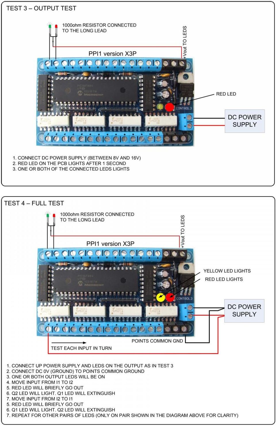
7 Troubleshooting The following diagrams show four tests which can be conducted to determine if the PPI is operating correctly.

8
POINTS POSITION INDICATOR PPI4
 POINTS POSITION INDICATOR PPI4 Advanced PPI with Adjustable Brightness & Simplified Wiring Monitors the brief positive operating voltage across points motors when they are switched Lights a corresponding
MIDECO 64-outputs MIDI note decoder USER MANUAL. Roman Sowa 2012
 MIDECO 64-outputs MIDI note decoder USER MANUAL Roman Sowa 2012 www.midi-hardware.com 1.Overview Thank you for choosing MIDECO as your new MIDI-to-digital converter. This short manual will guide you through
BLOCK OCCUPANCY DETECTOR WITH SEMAPHORE OPERATION BOD1/DAP4-BR
 BLOCK OCCUPANCY DETECTOR WITH SEMAPHORE OPERATION BOD1/DAP4-BR This Block Occupancy Detector recognises the current drawn by moving trains within a block, and can operate a number of built-in programs
LG Air Conditioning Multi F(DX) Fault Codes Sheet. Multi Split Units
 Fault Codes Sheet. Multi Split Units") Multi Split Units If there is a fault on any LG Multi unit, an Error mark is indicated on the display window of the indoor unit, wired-remote controller, and LED s of outdoor unit control board. A two
Multi Split Units If there is a fault on any LG Multi unit, an Error mark is indicated on the display window of the indoor unit, wired-remote controller, and LED s of outdoor unit control board. A two
PUSH BUTTON START INSTALLATION MANUAL
 PUSH BUTTON START INSTALLATION MANUAL ALTHOUGH THIS PRODUCT HAS BEEN THOROUGHLY TESTED KPIERSON TECHNOLOGIES ASSUMES NO RESPONSIBILITY FOR ANY DAMAGE THAT MAY RESULT BY THE INSTALLATION OF THIS PRODUCT.
Data sheet GIOD.1 Input/output module with CAN bus. ERP no.: 5204183. www.guentner.de. Data sheet GIOD.1 V_3.0
 Data sheet GIOD.1 Input/output module with CAN bus ERP no.: 5204183 www.guentner.de Page 2 / 10 Contents 1 GIOD.1... 3 1.1 Functional description...3 1.2 Connections... 5 1.3 Electrical properties of...
Data Sheet. Adaptive Design ltd. Arduino Dual L6470 Stepper Motor Shield V1.0. 20 th November 2012. L6470 Stepper Motor Shield
 Arduino Dual L6470 Stepper Motor Shield Data Sheet Adaptive Design ltd V1.0 20 th November 2012 Adaptive Design ltd. Page 1 General Description The Arduino stepper motor shield is based on L6470 microstepping
PRODUCTIVITY THROUGH INNOVATION 600 CONTROL DIRECT DRIVE TECHNICAL/OPERATION MANUAL
 Rev. D PRODUCTIVITY THROUGH INNOVATION 600 CONTROL DIRECT DRIVE TECHNICAL/OPERATION MANUAL 10 BORIGHT AVENUE, KENILWORTH NEW JERSEY 07033 TELEPHONE: 800-524-0273 FAX: 908-686-9317 TABLE OF CONTENTS Page
Instruction Manual. This Manual covers the use of: SmartSwitch Servo Kit. DCC Stationary Decoder PLEASE READ THESE INSTRUCTIONS FULLY BEFORE USE
 built by Instruction Manual This Manual covers the use of: PLS-125 PLS-130 PLS-135 SmartSwitch Servo Kit SmartFrog DCC Stationary Decoder PLEASE READ THESE INSTRUCTIONS FULLY BEFORE USE Contents Introduction
Fitting/Installation Guide - UNIVERSAL
 ATTENTION: This wiring information is being provided free of charge and on an as is basis, without any representation or warranty. It is your responsibility to verify any circuit before interfacing with
Programming Logic controllers
 Programming Logic controllers Programmable Logic Controller (PLC) is a microprocessor based system that uses programmable memory to store instructions and implement functions such as logic, sequencing,
Gates, Circuits, and Boolean Algebra
 Gates, Circuits, and Boolean Algebra Computers and Electricity A gate is a device that performs a basic operation on electrical signals Gates are combined into circuits to perform more complicated tasks
CM705B - Universal Expander Module CM707B - Plug On Zone Expander Security Systems
 CM705B - Universal Expander Module CM707B - Plug On Zone Expander Security Systems EN Security System CM705B CM705B - Universal Expander Module The CM705B universal expander provides a cost effective way
Operating instructions Diffuse reflection sensor. OJ50xx 701396 / 01 07 / 2004
 Operating instructions Diffuse reflection sensor OJ50xx 7096 / 0 07 / 004 Contents Preliminary note. Symbols used Function and features Installation. Installation of the supplied mounting fixture 4 4 Electrical
Robot Board Sub-System Testing. Abstract. Introduction and Theory. Equipment. Procedures. EE 101 Spring 2006 Date: Lab Section # Lab #6
 EE 101 Spring 2006 Date: Lab Section # Lab #6 Name: Robot Board Sub-System Testing Partner: No Lab partners this time! Abstract The ECEbot robots have a printed circuit board (PCB) containing most of the
Operating instructions Switching amplifier for fibre optics. OBF5xx 704876 / 00 08 / 2010
 Operating instructions Switching amplifier for fibre optics OBF5xx 70876 / 00 08 / 00 Contents Preliminary note. Symbols used Functions and features. Applications Installation. Attaching the fibre optics
Electric Landing Gear controllers and sequencer LGC12 / LGC 13C
 Electric Landing Gear controllers and sequencer LGC12 / LGC 13C Users Guide. Torrent d en Puig, 31. 08358, Arenys de Munt, Barcelona,Catalonia,Spain E-mail: info@xicoy.com. Fax: +34 933 969 743 web: www.xicoy.com
DSTV DECODER SETUP MANUAL July 2013
 DSTV DECODER SETUP MANUAL July 2013 DSTV SINGLE VIEW AND SD PVR DECODER SETUP How to program your Single View and SD PVR DSTV Decoders STEP 1 Ensure that the DSTV decoder is connected correctly to the
Multimeter measurements on variable frequency drives using the new Fluke 289 DMM
 Multimeter measurements on variable frequency drives using the new Fluke 289 DMM Application Note Editor s note: For similar instructions using the Fluke 87V DMM, reference Fluke article 12345. In the
BODY ELECTRICAL MAZDA
 BODY ELECTRICAL ASSIGNMENT WORKSHEETS Version 1.3 MAZDA ELECTRICAL WIRING DIAGRAM WORKBOOK http://www.autoshop101.com Developed by Kevin R. Sullivan All rights reserved. MAZDA Table of Contents Wiring
RADIANT PLASMA 4700 Plasma Spark Generator
 RADIANT PLASMA 4700 Plasma Spark Generator Installation Guide / User Manual A S P A R K O F F R E S H A I R Aquapulser.com Contents 1 Introduction 2 1.1 About the Product....................................
Your Multimeter. The Arduino Uno 10/1/2012. Using Your Arduino, Breadboard and Multimeter. EAS 199A Fall 2012. Work in teams of two!
 Using Your Arduino, Breadboard and Multimeter Work in teams of two! EAS 199A Fall 2012 pincer clips good for working with breadboard wiring (push these onto probes) Your Multimeter probes leads Turn knob
BODY ELECTRICAL TOYOTA ELECTRICAL WIRING DIAGRAM WORKBOOK. ASSIGNMENT Version 1.8 WORKSHEETS. http://www.autoshop101.com
 BODY ELECTRICAL ASSIGNMENT Version 1.8 WORKSHEETS TOYOTA ELECTRICAL WIRING DIAGRAM WORKBOOK http://www.autoshop101.com Developed by Kevin R. Sullivan All Rights Reserved TOYOTA Table of Contents Wiring
MODEL 5010 DUAL CHANNEL SMOKE/FIRE DETECTION MODULE
 DESCRIPTION MODEL 5010 DUAL CHANNEL SMOKE/FIRE DETECTION MODULE DESCRIPTION The SST Model 5010 Two Channel Smoke/Fire Detection Module provides two independent detection input channels for the NOVA-5000
RCDC1 Radio Controlled Device Controller- 1 Channel
 RCDC1 Radio Controlled Device Controller- 1 Channel When the Mode Switch is in Position 1, Moving the joystick forward turns on the relay. When the joystick returns to center, the relay goes off (momentary
Design Project: Power inverter
 Design Project: Power inverter This worksheet and all related files are licensed under the Creative Commons Attribution License, version 1.0. To view a copy of this license, visit http://creativecommons.org/licenses/by/1.0/,
Wires & Connections Component Circuit Symbol Function of Component. Power Supplies Component Circuit Symbol Function of Component
 Lista Dei Simboli Dei Circuiti Per i Componenti Elettronici Wires & Connections Wire Wires joined Wires not joined To pass current very easily from one part of a circuit to another. A 'blob' should be
SYSTEM 4C. C R H Electronics Design
 SYSTEM 4C C R H Electronics Design SYSTEM 4C All in one modular 4 axis CNC drive board By C R Harding Specifications Main PCB & Input PCB Available with up to 4 Axis X, Y, Z, A outputs. Independent 25
AUTODIALLER / QUICKDIALLER - SA132
 AUTODIALLER / QUICKDIALLER - SA132 INSTRUCTION LEAFLET ENGLISH www.thermomax-group.com CONTENTS 1 SETUP AT A GLANCE... 2 2 FOREWORD....... 3 3 INSTALLATION...... 4 4 KEYPAD AND INDICATORS...... 5 SETTING
3BASIC RELAY INSTRUCTIONS
 M O D U L E T H R E E 3BASIC RELAY INSTRUCTIONS Key Points So far, you have learned about the components of the MicroLogix 1000 PLC, including the CPU, the memory system, the power supply, and the input/output
Digital I/O: OUTPUT: Basic, Count, Count+, Smart+
 Digital I/O: OUTPUT: Basic, Count, Count+, Smart+ The digital I/O option port in the 4-Series provides us with 4 optically isolated inputs and 4 optically isolated outputs. All power is supplied externally.
i ChatterBox! Motorcycle Security
 i Before you Start the Installation * Please read this manual to become familiar with the requirements necessary to complete the installation. * Use a high quality multi-meter to test all wires before
SUBJECT: How to wire a motor starter Number: AN-MC-004 Date Issued: 2/08/2005 Revision: Original
 SUBJECT: How to wire a motor starter Number: AN-MC-004 Date Issued: 2/08/2005 Revision: Original A motor starter is a combination of devices to allow an induction motor to start, run and stop according
Table 1 Comparison of DC, Uni-Polar and Bi-polar Stepper Motors
 Electronics Exercise 3: Uni-Polar Stepper Motor Controller / Driver Mechatronics Instructional Laboratory Woodruff School of Mechanical Engineering Georgia Institute of Technology Lab Director: I. Charles
Operation Manual. Plasma torch height controller. Model: Compact THC Controller 150
 Operation Manual Plasma torch height controller. Model: Compact THC Controller 150 Notes on safety WHEN THE DEVICE IS IN OPERATION, VOLTAGE HAZARDOUS TO HEALTH AND HUMAN LIFE IS PRESENT INSIDE THE HOUSING
Building the AMP Amplifier
 Building the AMP Amplifier Introduction For about 80 years it has been possible to amplify voltage differences and to increase the associated power, first with vacuum tubes using electrons from a hot filament;
CHAPTER 11: Flip Flops
 CHAPTER 11: Flip Flops In this chapter, you will be building the part of the circuit that controls the command sequencing. The required circuit must operate the counter and the memory chip. When the teach
How To Power A Power Control On An Ip40 (Ipl) With A Power Supply (Iplug) With An Ip20 Controller (Iphones) With Power Control (Power Control) With No Antenna) With The Ip20 (Power)
 With A Power Supply (Iplug) With An Ip20 Controller (Iphones) With Power Control (Power Control) With No Antenna) With The Ip20 (Power)") MODEL NUMBER: ISC910-1-0-GB-XX ISC911-5-0-GB-XX IXP20 CONTROLLER SPECIFICATIONS Working Environment Plastic Housing... Power ImproX IXP20 Controller INSTALLATION MANUAL Designed to work in an indoor (dry)
MODEL NUMBER: ISC910-1-0-GB-XX ISC911-5-0-GB-XX IXP20 CONTROLLER SPECIFICATIONS Working Environment Plastic Housing... Power ImproX IXP20 Controller INSTALLATION MANUAL Designed to work in an indoor (dry)
SPROG II User Guide 1. SPROG II DCC Decoder Programmer User Guide
 SPROG II User Guide 1 SPROG II DCC Decoder Programmer User Guide Firmware version 2.x December 2007 SPROG II User Guide 2 Table of Contents Introduction... 4 Requirements... 4 Requirements... 4 Features...
BUILD YOUR OWN RC SWITCH (Issue 3)
") PART ONE SINGLE ELECTRONIC RC SWITCH Fancy switching the lights using your radio, then here is a circuit you may consider building. It only uses one IC and seven other components for a single switch and
PART ONE SINGLE ELECTRONIC RC SWITCH Fancy switching the lights using your radio, then here is a circuit you may consider building. It only uses one IC and seven other components for a single switch and
ABB Drives. User s Manual HTL Encoder Interface FEN-31
 ABB Drives User s Manual HTL Encoder Interface FEN-31 HTL Encoder Interface FEN-31 User s Manual 3AUA0000031044 Rev B EN EFFECTIVE: 2010-04-06 2010 ABB Oy. All Rights Reserved. 5 Safety instructions
High voltage power supply (1 to 20 KV)
") High voltage power supply ( to 0 KV) Ammar Ahmed Khan, Muhammad Wasif, Muhammad Sabieh Anwar This documentation is divided into two parts, the first part provides a brief overview about the key features
High voltage power supply ( to 0 KV) Ammar Ahmed Khan, Muhammad Wasif, Muhammad Sabieh Anwar This documentation is divided into two parts, the first part provides a brief overview about the key features
maxon motor maxon motor control EPOS Positioning Controller Cable Starting Set Edition June 2006 part number 302287 Positioning Controller
 control EPOS Positioning Controller Cable Starting Set Edition June 2006 24/1 part number 302287 Positioning Controller Documentation Cable Starting Set 1 Table of contents 1 Table of contents... 2 2 Table
Miniature High-Resolution Registration Mark Sensor White LED AUTOSET Remote Setup Option
 REGISTRATION MARK SENSORS MARK EYE PRO 2 Miniature High-Resolution Registration Mark Sensor White LED AUTOSET Remote Setup Option Registration Mark Photoelectric Sensors 2-115 High-Resolution Registration
M1000 Process Alarm Monitor
 Data Sheet Process Alarm Monitor Reliable Supervision and Control 10 inputs with LED indications Supports both NO/NC input contacts 10 open collector outputs Built-in siren relay Text label for alarm descriptions
Modification of an AOR AR-8600 receiver to tune it with a ACECO FC-3002 frequency finder
 Modification of an AOR AR-8600 receiver to tune it with a ACECO FC-3002 frequency finder Matthias DD1US updated June 2 nd 2011 Description of the ACECO FC-3002 unit: The ACECO FC-3002 is a handheld frequency
Troubleshooting and Diagnostics
 Troubleshooting and Diagnostics The troubleshooting and diagnostics guide provides instructions to assist in tracking down the source of many basic controller installation problems. If there is a problem
SYSTEM 45. C R H Electronics Design
 SYSTEM 45 C R H Electronics Design SYSTEM 45 All in one modular 4 axis CNC drive board By C R Harding Specifications Main PCB & Input PCB Available with up to 4 Axis X, Y, Z, & A outputs. Independent 25
K8025 VIDEO PATTERN GENERATOR. Check the picture quality of your monitor or TV, ideal for adjustment or troubleshooting.
 K8025 ILLUSTRATED ASSEMBLY MANUAL H8025IP 1 VIDEO PATTERN GENERATOR Check the picture quality of your monitor or TV, ideal for adjustment or troubleshooting. Forum Participate our Velleman Projects Forum
GLOLAB Universal Telephone Hold
 GLOLAB Universal Telephone Hold 1 UNIVERSAL HOLD CIRCUIT If you have touch tone telephone service, you can now put a call on hold from any phone in the house, even from cordless phones and phones without
USER MANUAL ESP. Enhanced Steering Performance. R-Net
 USER MANUAL US ESP Enhanced Steering Performance R-Net ESP Enhanced Steering Performance R-Net Produced and published by Permobil AB, Sweden Edition 1, 2008-04 Product code: 205229-US-0 How to contact
Hatton s MD4 Decoder. Thank you for purchasing Hatton s Decoders.
 Thank you for purchasing Hatton s Decoders. Hatton s MD4 Decoder Our decoder meets all NMRA DCC specifications and will give good performance out of the pack, however by using this manual, you can learn
8 coil stator 11 coil stator
 Below is a schematic of a typical scooter electrical set up as far as the stator, CDI, rectifier/regulator go along with the other items running on the electrical system; This is the 6 coil stator common
Fundamentals of Signature Analysis
 Fundamentals of Signature Analysis An In-depth Overview of Power-off Testing Using Analog Signature Analysis www.huntron.com 1 www.huntron.com 2 Table of Contents SECTION 1. INTRODUCTION... 7 PURPOSE...
Introduction to Electronic Signals
 Introduction to Electronic Signals Oscilloscope An oscilloscope displays voltage changes over time. Use an oscilloscope to view analog and digital signals when required during circuit diagnosis. Fig. 6-01
Stop Alert Flasher with G-Force sensor
 Stop Alert Flasher with G-Force sensor Stop Alert module creates brake light flashing effect to catch attention of the drivers behind to avoid dangerous rear end collision. The flasher module is a state
GLOLAB Two Wire Stepper Motor Positioner
 Introduction A simple and inexpensive way to remotely rotate a display or object is with a positioner that uses a stepper motor to rotate it. The motor is driven by a circuit mounted near the motor and
PolyBot Board. User's Guide V1.11 9/20/08
 PolyBot Board User's Guide V1.11 9/20/08 PolyBot Board v1.1 16 pin LCD connector 4-pin SPI port (can be used as digital I/O) 10 Analog inputs +5V GND GND JP_PWR 3-pin logic power jumper (short top 2 pins
Table of Contents. The Basics of Electricity 2. Using a Digital Multimeter 4. Testing Voltage 8. Testing Current 10. Testing Resistance 12
 Table of Contents The Basics of Electricity 2 Using a Digital Multimeter 4 IDEAL Digital Multimeters An Introduction The Basics of Digital Multimeters is designed to give you a fundamental knowledge of
ALARM ANNUNCIATOR ME - 3010 INSTRUCTION MANUAL
 ALARM ANNUNCIATOR ME - 3010 INSTRUCTION MANUAL INTRODUCTION... 2.. TECHNICAL DATA... 3 ACCESSORIES... 5. INSTALLATION... 7 OPERATION... 12. TECHNICAL INFORMATION... 13 MAINTENANCE... 14. CONFIGURATIONS...
ENCODER TEST MODULE APPLICATION GUIDE
 ENCODER TEST MODULE APPLICATION GUIDE MODEL NUMBER: EM-DR1-ET-5-TB-4469-24V PART NUMBER: 924-60002-001 7230 Hollister Avenue, Goleta, CA 93117-2891 Phone: (800)362-6337 or (800)938-0782 Fax: (800)960-2726
Basic Setup Guide. browndoggadgets.com. 12V Solar Charge Controller with Dual USB. Dull Introduction
 Solar Charge Controller with USB Basic Setup Guide browndoggadgets.com In this guide we will show you how to do a basic setup for all three of our Solar Charge Controllers with USB. Models Covered 6V Solar
TEECES DOME LIGHTING SYSTEMS
 This lighting system was designed by John V (Teeces) to be a simple, customizable, expandable and affordable solution for dome lighting. An Arduino micro-controller is used to tell LED driver chips which
User Manual for CH-PFC76810
 AA Portable Power Corp www.batteryspace.com, Email: Sales@batteryspace.com User Manual for CH-PFC76810 1. Overview The CH-PFC76810 charger is suitable for charging lithium ion battery packs such as those
Data Sheet. Electro-mechanical counters Hengstler 800 series
 Data Pack D Issued March 00 504897 Data Sheet Electro-mechanical counters Hengstler 800 series The 800 series totalising and predetermining batch counters, manufactured by Hengstler, is available from
Snap-It. This is an accessory (switch machine) decoder
 decoder") Snap-It $19.95 For use with most twin coil switch machines such as: Atlas, LifeLike, Peco, Bachmann, NJ, Rix, Kemtron and others Dimensions: 1.80" x 1.50" (46 x 38 mm) This is an accessory (switch machine)
Snap-It $19.95 For use with most twin coil switch machines such as: Atlas, LifeLike, Peco, Bachmann, NJ, Rix, Kemtron and others Dimensions: 1.80" x 1.50" (46 x 38 mm) This is an accessory (switch machine)
Multi-Protocol decoder 76 200 with Load regulation
 Multi-Protocol decoder 76 2 with Load regulation For locomotives with universal motors on digital layouts operating in the DCC and Motorola data format. Features 76 2 Load regulated multi-protocol decoder
AXE114S BINARY CLOCK. revolution Revolution Education Ltd. Email: info@rev-ed.co.uk Web: www.rev-ed.co.uk Version 1.1 12/09/08 AXE114.PMD.
 AXE114S BINARY CLOCK Features: The PICAXE binary clock kit tells the time by lighting up blue LEDs in a binary pattern. This is a useful tool for teaching students binary code or simply just confusing/
AN ISOLATED GATE DRIVE FOR POWER MOSFETs AND IGBTs
 APPLICATION NOTE AN ISOLATED GATE DRIVE FOR POWER MOSFETs AND IGBTs by J.M. Bourgeois ABSTRACT Power MOSFET and IGBT gate drives often face isolation and high voltage constraints. The gate drive described
FIREDEX 2200. Conventional Fire Panels
 68 Flexible, high specification system Choice of 1, 2, 4 or 8 zones Simple one-shot auto-reset user test facility Approved to EN54 Maintenance free poly switch circuit protection, with auto reset Class
PRO PLM Installation Instructions
 PRO PLM Installation Instructions PROFESSIONAL INSTALLATION STRONGLY RECOMMENDED Installation Precautions: Roll down window to avoid locking keys in vehicle during installation Avoid mounting components
Quick Start Guide for High Voltage Solar Inverter DC-AC Board EVM. Version 1.3
 Quick Start Guide for High Voltage Solar Inverter DC-AC Board EVM Version 1.3 Introduction This document talks about the quick start principles for the high voltage solar inverter DC-AC board. From this
Alarm over IP. IRIS Touch Home Installation Manual. Version 1.0 ENGLISH. Now certified and compliant with EN50131, EN50136 Security Grade 4 ATS6
 Alarm over IP IRIS Touch Home Installation Manual Version 1.0 ENGLISH Now certified and compliant with EN50131, EN50136 Security Grade 4 ATS6 1. Introduction No more bulky batteries, just one sleek unit
Properties of electrical signals
 DC Voltage Component (Average voltage) Properties of electrical signals v(t) = V DC + v ac (t) V DC is the voltage value displayed on a DC voltmeter Triangular waveform DC component Half-wave rectifier
What Is Regeneration?
 What Is Regeneration? Braking / Regeneration Manual Regeneration Overview Revision 1.0 When the rotor of an induction motor turns slower than the speed set by the applied frequency, the motor is transforming
Switches and Indicators. Swisstac
 Switches and Indicators Switches and Indicators Index Series Description Page 583 Product Assembly Page 584 Mounting Instruction Page 585 Product Range - pushbuttons for standard mounting - pushbuttons
Emergency Voice Communication Systems EVCS Network 8 Data Sheet
 Emergency Voice Communication Systems EVCS Network 8 Data Sheet The Emergency Voice Communications System (EVCS) Network 8 is for use as a Fire Telephone system, Disabled Refuge Call system or as a combined
AUTOMATIC TRANSFER SWITCH CONTROL UNIT OPERATOR S MANUAL
 ATS-220 AUTOMATIC TRANSFER SWITCH CONTROL UNIT OPERATOR S MANUAL For Use in 208 to 240 Volts Single and 3 Phase ATS Systems With 110Volt AC or DC Control Motors and selenoids 4501 NW 27 ave Miami FL 33142
1R / 4-BUTTON SERIES
 Button 1 1R / 4-BUTTON SERIES VEHICLE SECURITY SYSTEM Standard Features: Two 4-Button Remote Transmitters Status indicator (LED) Valet / override switch Multi-tone siren Dual stage impact detector Remote
EXPERIMENT NUMBER 5 BASIC OSCILLOSCOPE OPERATIONS
 1 EXPERIMENT NUMBER 5 BASIC OSCILLOSCOPE OPERATIONS The oscilloscope is the most versatile and most important tool in this lab and is probably the best tool an electrical engineer uses. This outline guides
CONTROL SWITCHER User s Manual (Preliminary)
") CONTROL SWITCHER User s Manual (Preliminary) www.voodoolab.com Copyright 2010 by Digital Music Corporation. This publication is protected by copyright and all rights are reserved. Voodoo Lab, Control Switcher,
CONTROL SWITCHER User s Manual (Preliminary) www.voodoolab.com Copyright 2010 by Digital Music Corporation. This publication is protected by copyright and all rights are reserved. Voodoo Lab, Control Switcher,
Pulse Width Modulation (PWM) LED Dimmer Circuit. Using a 555 Timer Chip
 LED Dimmer Circuit. Using a 555 Timer Chip") Pulse Width Modulation (PWM) LED Dimmer Circuit Using a 555 Timer Chip Goals of Experiment Demonstrate the operation of a simple PWM circuit that can be used to adjust the intensity of a green LED by varying
Pulse Width Modulation (PWM) LED Dimmer Circuit Using a 555 Timer Chip Goals of Experiment Demonstrate the operation of a simple PWM circuit that can be used to adjust the intensity of a green LED by varying
Instructions for TF2 Digitrax Dual Function Decoder w/transponder. TF2 DCC Dual Function Decoder with Transponder
 Instructions for Digitrax Dual Function Decoder w/transponder 450 Cemetery ST #206 Norcross, GA USA 30071 (770)441-7992 FAX (770)441-0759 Web Site: http://www.digitrax.com Digitrax Command Control DCC
Using Arduino Microcontrollers to Sense DC Motor Speed and Position
 ECE480 Design Team 3 Using Arduino Microcontrollers to Sense DC Motor Speed and Position Tom Manner April 4, 2011 page 1 of 7 Table of Contents 1. Introduction ----------------------------------------------------------
Frequency Converter Fv
 2 Bosch Rexroth AG Electric Drives and Controls Documentation Brake chopper with up to 30 kw continuous braking power Easy to operate and service (detachable fan, LCD operating panel with copy function)
Telefon (+45) 43 43 82 00 Telefax (+45) 43 43 74 75 mail@uni-valve.com www.uni-valve.com. Installation and operating manual
 43 43 82 00 Telefax (+45) 43 43 74 75 mail@uni-valve.com www.uni-valve.com. Installation and operating manual") Uni-Valve A /S VENTILER & INSTRUMENTER Telefon (+45) 43 43 82 00 Telefax (+45) 43 43 74 75 mail@uni-valve.com www.uni-valve.com UNI-EL Electric actuator Installation and operating manual Remote position
Uni-Valve A /S VENTILER & INSTRUMENTER Telefon (+45) 43 43 82 00 Telefax (+45) 43 43 74 75 mail@uni-valve.com www.uni-valve.com UNI-EL Electric actuator Installation and operating manual Remote position
K6002 TEMPERATURE CONTROLLER. Specifications
 Total solder points: 169 + 99 + 67 Difficulty level: beginner 1 2 3 4 5 advanced TEMPERATURE CONTROLLER K6002 Unlike a normal thermostat, this kit has two outputs, one for "high" alarm and one for "low"
Transmitter Interface Program
 Transmitter Interface Program Operational Manual Version 3.0.4 1 Overview The transmitter interface software allows you to adjust configuration settings of your Max solid state transmitters. The following
0832 Dot Matrix Green Display Information Board User s Guide
 0832 Dot Matrix Green Display Information Board User s Guide DE-DP105_Ver1.0 0832 DOT MATRIX GREEN DISPLAY INFORMATI BOARD USER S GUIDE Table of contents Chapter1.Overview... 1 1.1. Welcome... 1 1.2. Quick
TX GSM SMS Auto-dial Alarm System. Installation and User Manual
 TX GSM SMS Auto-dial Alarm System Installation and User Manual Product Features: 1. 16 wireless zones, 3 wired zones alarm system, suitable for small to medium size offices and homes. 2. The system uses
Analogue Input, 4-fold, MDRC AE/S 4.1, GH Q605 0054 R0001
 Analogue Input, -fold, MDRC, GH Q605 005 R0001 The analogue input is a DIN rail mounted device for insertion in the distribution board. It is connected to the EIB via the bus connecting terminal supplied.
.OPERATING SUPPLY VOLTAGE UP TO 46 V
 L298 DUAL FULL-BRIDGE DRIVER.OPERATING SUPPLY VOLTAGE UP TO 46 V TOTAL DC CURRENT UP TO 4 A. LOW SATURATION VOLTAGE OVERTEMPERATURE PROTECTION LOGICAL "0" INPUT VOLTAGE UP TO 1.5 V (HIGH NOISE IMMUNITY)
INSTALLATION & SERVICE MANUAL. Display Panel
 INSTALLATION & SERVICE MANUAL Display Panel The PowerLine EMS TM is a specialized power distribution and energy management system intended to be used in recreational vehicles. The Control Module is housed
FREQUENCY RESPONSE OF AN AUDIO AMPLIFIER
 2014 Amplifier - 1 FREQUENCY RESPONSE OF AN AUDIO AMPLIFIER The objectives of this experiment are: To understand the concept of HI-FI audio equipment To generate a frequency response curve for an audio
LG Air Conditioning - Universal Split Fault Codes Sheet. Universal Split Systems
 Universal Split Systems If there is a fault on any LG Universal unit, a two digit number will appear on the remote controllers led display. If the unit does not have a remote controller the fault will
ELECTRONIC THERMOSTAT AND THERMOMETER With SPEED CONTROL
 148 OLD CONCORD TURNPIKE, BARRINGTON NH 03825 USA TEL (603) 868-5720 FAX (603) 868-1040 1-800-435-6708 E-Mail:sales@seafrost.com www.seafrost.com ELECTRONIC THERMOSTAT AND THERMOMETER With SPEED CONTROL
ABB Drives. User s Manual. Pulse Encoder Interface Module RTAC-01
 ABB Drives User s Manual Pulse Encoder Interface Module RTAC-0 Pulse Encoder Interface Module RTAC-0 User s Manual 3AFE 64486853 REV A EN EFFECTIVE:.5.00 00 ABB Oy. All Rights Reserved. Safety instructions
ECEN 1400, Introduction to Analog and Digital Electronics
 ECEN 1400, Introduction to Analog and Digital Electronics Lab 4: Power supply 1 INTRODUCTION This lab will span two lab periods. In this lab, you will create the power supply that transforms the AC wall
www.curtisinstruments.com
 CANBUS I/O EXPANSION MODULE MODELS 56 / 56P FEATURES Eighteen multi-purpose I/O pins provide simple, flexible vehicle control system expansion. Two high-frequency (A, A) PWM driver outputs support a variety