Switches and Indicators. Swisstac
|
|
|
- Alberta Austin
- 7 years ago
- Views:
Transcription
1 Switches and Indicators
2 Switches and Indicators Index Series Description Page 583 Product Assembly Page 584 Mounting Instruction Page 585 Product Range - pushbuttons for standard mounting - pushbuttons for flush mounting - accessories / spare parts Technical Data Page 591 Page 608 Page 622 Page 638 Drawing / Dimension / Layouts Page 642 Circuit Drawing Page 657 Marking Page

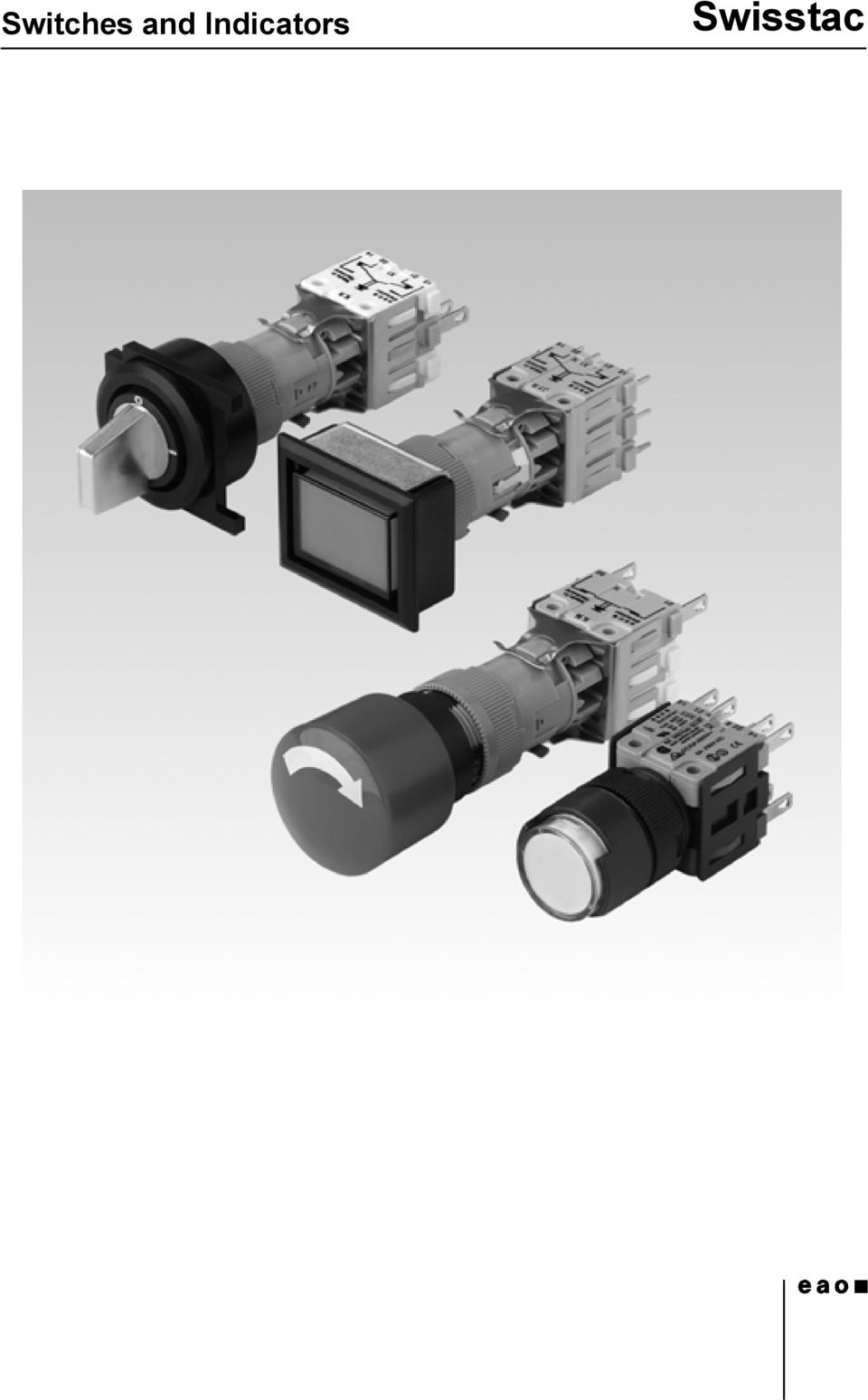
3 Description SWISSTAC - Three crucial advantages! Easy storage in minimum space Every SWISSTAC switch can be altered very simply any number of times, and afterwards added to, modified or adapted. This highly modular concept means that only a few subassemblies reducing storage costs. All connections on one plane All the terminals are arranged at the same level, are clearly laid out and fully accessible even when in close-packed arrays. Three colours provide optical help to make connections easier. Ideal for switch interlock systems SWISSTAC switches can be mechanically combined in many ways to form switch interlock systems and in fact in rows of up 20 switches. This means that complicated protection and relay interlocks are unnecessary. Individual and irregular spacings between the switches of an array are no problem either. Marking Engraved, printed film inlay see under Marking page 667. Illumination Perfect illumination of the lenses supplied in various colours is guaranteed by the incandescent lamps midget grooved T 1 3/4 and T 5.5 (6-60V9). Where supply voltages are over 60 V, a voltage-reduction element (ext. protective series resistor or capacitor) must be used. Because of high surface temperature, the protective series resistor may not be soldered direct onto the connections of the pushbuttons. Multi-LED midget grooved T 1 3/4 and T 5.5 (6, 12, 24, 48 V) are available in the colours red, yellow and green. Switch position indicator When the pushbutton with latch function is operated, the lens latches in mechanically. The position of the lens makes the switch position evident at all the times. CE Our products are marked with the internationally approved CE lowvoltage safety standard. General information, a modularly constructed control switch system, offers the user a wide range of products: buzzers, illuminated pushbuttons and pushbuttons, indicators, emergency stop switches, push-pull illuminated switches, keylock switches and selector switches, as well as switch interlock systems in the front-facing protection classes IP 40 and IP 65. The front dimensions of the switch units are: 18 mm dia., 18 x 18 mm, 24 mm dia., 24 x 24 mm. For flush mounting, dimensions 25 mm dia., 24 x 24 mm, 24 x 30 mm are also available. Construction SWISSTAC switches are of modular construction and are divided into the following three groups: - Front section: Man/switch interface and status indicator two-part lens for engraving, film insert or printing - Intermediate section: Latching/ pulse facility, lamp holder, latch function - Intermediate section with switching mechanism and lamp holder, which is available in two versions: T: 5.5 max., 1.2 W and midget grooved T 1 3/4 max. Keylock switches Standard lock 1 Standard number is B We supply B2 300 without specifications of the lock numbers. Four further standard locks are B B This additional designation should be quoted when ordering. A further 95 locks are available in or without passepartout version on request. 2 keys are supplied per keylock switch. Spare keys for a standard lock can be ordered under Type no ( plaese quote lock number). Example: B Emergency stop switch with key to unlock Standard lock is B Four further standard locks are B B When ordering this additional designation should be quoted. Spare keys for standard lock can be ordered under Type no (please quote lock). Example: B Two keys are supplied per emergency stop switch. Emergency Stop Switch, foolproof with key to unlock Kaba safety switch. Standard lock number is Spare keys can be ordered under Type no keys are supplied per emergency stop switches. 1.2 W. - Terminal block: up to a max. of five switching elements can be joined together in one switch terminal block. Are supplied mounted serially on intermediate sections. Can be disassembled easily for wiring. All measurements in mm Technical specifications subject to modification. 583

4 product assembly illuminated-/pushbutton 1 lens 2 front bezel 3 fixing nut 4 spring with pin for changing from maintained to momentary 5 intermediate section 6 holder for switching element 7 switching element block 8 switching element 0 pushbutton-/illuminated pushbutton for flush mounting 1 lens 2 front bezel 3 front bezel set f. fl. mounting 4 front panel 5 fixing nut 6 spring with pin f. changing from main to mom 7 intermediate section 8 holder f. switching element 9 switching element block 10 switching element 0 584

5 Mounting Instruction illuminated-/pushbutton 35mm The switch is mounted in a fascia or control panel in three steps: 1. Detach terminal block as in drawing, remove fixing nut 2. Insert switch from the front in fascia/control panel 3. Reassemble the switch in the reverse order To detach terminal block Note: Type-identification on legs of actuator illuminated-/pushbutton mm The switch is mounted in a fascia/control panel in two steps: 1. Insert switch from back side in fascia/control panel 2. Snap on bezel and tighten fixing nut Lens Bezel Illuminated pushbutton illuminated-/pushbutton mm sealing gland and -ring The first time the button is pressed, the gland is forced into its groove and becomes effective. 585

6 Mounting Instruction indicator mm The indicator is mounted in a fascia/control panel in two steps: 1. Insert indicator from back side in fascia/control panel 2. Snap on bezel and tighten fixing nut 2 Lens Bezel Indicator indicator mm sealing gland, -ring and press ring The press ring is fitted between gland and lens. The seal is effective when the lens is snapped into place. emergency stop switch turn to release mm The switch is mounted in a fascia or control panel in three steps: 1. Detach front section just in released position, as in drawing 2. Insert switch from back side in fascia/control panel 3. Snap on front section and tighten fixing nut Important for IP 65 With models to IP 65, the sealing ring 1) is already fitted Sealing ring2) is fitted as standard This must be removed if the SWISSTAC emergency in models to IP 65. Stop identity plate (IP 65 model) is used. Zero position Identity plate Wiring diagram 586

7 Mounting Instruction emergency stop switch with key release mm The switch is mounted in a fascia or control panel in three steps: 1. Detach front section, just in released position, as in drawing, remove fixing nut 2. Insert switch from back side in fascia/control panel 3. Snap on front section and tighten fixing nut Important for IP 65 With models to IP 65, the sealing ring1)is already fitted Sealing ring2) is fitted as standard This must be removed if the SWISSTAC emergency in models to IP 65. Stop identity plate (IP 65 model) is used. Zero position Identity plate Wiring diagram emergency stop switch foolproof Hint for mounting: the torque with which the fixing nut is tightened must not exceed 50 Ncm. Hint for dismounting: dismantling of switching element just with dismantling tool. keylock switch 45mm The switch is mounted in a fascia or control panel in three steps: 1. Detach terminal block as in drawing, remove fixing nut 2. Insert switch from front side in fascia/control panel 3. Reassemble the switch in the reverse order To detach terminal block 587
 is used.")
8 Mounting Instruction keylock switch 55 mm The switch is mounted in a fascia/control panel in three steps: 1. Remove front section as in drawing 2. Insert switch from back side in fascia/control panel 3. Snap on front section (see Note) and tighten fixing nut Zero position Wiring diagram To assemble, the key must be at the zero position, the symbol 0 is at the top, and on the terminal block the circuit diagram is uppermost. keylock switch 70 mm The switch is mounted in a fascia/control panel in three steps: 1. Remove front section as in drawing 2. Insert switch from back side in fascia/control panel 3. Snap on front section (see Note) and tighten fixing nut. Zero position Wiring diagram To assemble, the key must be at the zero position, the symbol 0 is at the top, and on the terminal block the circuit diagram is uppermost. selector switch 45 mm The switch is mounted in a fascia or control panel in three steps: 1. Detach terminal block as in drawing, remove fixing nut 2. Insert switch from front side in fascia/control panel 3. Reassemble the switch in the reverse order To detach terminal block 588

9 Mounting Instruction selector switch 55 mm The switch is mounted in a fascia/control panel in three steps: 1. Remove front section as in drawing 2. Insert switch from back side in fascia/control panel 3. Snap on front section (see Note) and tighten fixing nut Zero position Wiring diagram To assemble, the lever must be at the zero position, the symbol 0 is as the top, and on the terminal block the circuit diagram is uppermost. selector switch 70 mm The switch is mounted in a fascia/control panel in three steps: 1. Remove front section as in drawing 2. Insert switch from back side in fascia/control panel 3. Snap on front section (see Note) and tighten fixing nut Zero position Wiring diagram To assemble, the lever must be at the zero position, the symbol 0 is at the top, and on the terminal block the circuit diagram is uppermost. push pull illuminated switch The switch is mounted in a fascia or control panel in three steps: 1. Detach terminal block as in drawing, remove fixing nut 2. Insert switch from back side in fascia/control panel 3. Reassemble the switch in the reverse order Push-Pull knob To detach terminal block Push-pull knob can be mounted in only one position. Zero position Wiring diagram 589

10 Mounting Instruction buzzer mm The alarmbuzzer is mounted in a fascia/control panel in two steps: 1. Insert alarmbuzzer from backside in fascia/control panel 2. snap on bezel and tighten fixing nut buzzerelement bezel buzzerhousing 590

11 Pushbuttons for standard mounting indicator actuator 35 mm d lens for 35 mm page 622 d lamp element block for 35 mm page 632 d filament lamp MG T 1 3/4 page 634 d LED MG T 1 3/4 page 634 indicator actuator 35 mm lampholder MG T 1 3/4 degree of protection a 18 x 24 mm Typ-Nr. b 18 x 18 mm Typ-Nr. 18 mm dia. Typ-Nr. circuit drawing technical drawing mounting dimensions component layout IP ,004 IP W W W ,005 e circuit drawings from page 657, technical drawings from page 642, mounting dimensions from page 652, component layouts from page 657 indicator mm protection degree IP 40/IP 65 is determined by front bezel and lens d lens page 623 d front bezel for illuminated-/pushbutton mm and indicator mm page 627 d pressure ring page 630 d filament lamp MG T 1 3/4 page 634 d LED MG T 1 3/4 page 634 d filament lamp T 5.5 page 634 d LED T 5.5 page 635 mounting depth lamp socket part no. e indicator mm 30 mm - MG T 1 3/ K , mm - T K , mm P MG T 1 3/ P , mm - MG T 1 3/ , mm P T P , mm - T ,010 connection method : soldering-/plug-in terminal = -, PCB terminal = P The indicators 55 mm and 70 mm are as long as the corresponding illuminated pushbuttons and fit to the PCB plug-in base and multi-plug housing. circuit drawings from page 657, technical drawings from page 642, mounting dimensions from page 652, component layouts from page 657 connection method circuit drawing technical drawing mounting dimensions component layout 591

12 Pushbuttons for standard mounting pushbutton-/illuminated pushbutton actuator 35 mm d lens for 35 mm page 622 d filament lamp MG T 1 3/4 page 634 d LED MG T 1 3/4 page 634 d snap-action switching element block for 35 mm page 631 pushbutton-/illuminated pushbutton actuator 35 mm lampholder MG T 1 3/4 degree of protection switching action a 18 x 24 mm Typ-Nr. b 18 x 18 mm Typ-Nr. 18 mm dia. Typ-Nr. circuit drawing technical drawing mounting dimensions component layout IP 40 M ,004 MA ,004 IP 65 M W W W ,005 MA W W W ,005 e switching action : momentary action = M, maintained action = MA (changeable to momentary action, reversible) circuit drawings from page 657, technical drawings from page 642, mounting dimensions from page 652, component layouts from page

13 Pushbuttons for standard mounting illuminated-/pushbutton mm protection degree IP 40/IP 65 is determined by front bezel and lens d lens page 623 d front bezel for illuminated-/pushbutton mm and indicator mm page 627 d fialement lamp MG T 1 3/4 page 634 d filament lamp T 5.5 page 634 d LED T 5.5 page 635 mounting depth contacts : normally closed = NC, normally open = NO switching action : maintained action = MA (changeable to momentary action, reversible) connection method : PCB terminal = P, soldering-/plug-in terminal = - circuit drawings from page 657, technical drawings from page 642, mounting dimensions from page 652, component layouts from page 657 contacts switching action connection method lamp socket illuminated-/pushbutton mm 52 mm 1 NC + 1 NO MA P MG T 1 3/4 2 NC + 2 NO MA P MG T 1 3/4 3 NC + 3 NO MA P MG T 1 3/4 4 NC + 4 NO MA P MG T 1 3/4 5 NC + 5 NO MA P MG T 1 3/4 55 mm 1 NC + 1 NO MA - MG T 1 3/4 2 NC + 2 NO MA - MG T 1 3/4 3 NC + 3 NO MA - MG T 1 3/4 4 NC + 4 NO MA - MG T 1 3/4 5 NC + 5 NO MA - MG T 1 3/4 circuit drawing technical drawing mounting dimensions component layout part no. e P , P , P , P , P , , , , , , mm 1 NC + 1 NO MA P T P ,015 2 NC + 2 NO MA P T P ,016 3 NC + 3 NO MA P T P ,017 4 NC + 4 NO MA P T P ,020 5 NC + 5 NO MA P T P , mm 1 NC + 1 NO MA - T ,015 2 NC + 2 NO MA - T ,016 3 NC + 3 NO MA - T ,017 4 NC + 4 NO MA - T ,021 5 NC + 5 NO MA - T ,

14 Pushbuttons for standard mounting emergency stop switch mm d label for emergency stop switch page 636 emergency stop switch mm according to VDE max. 2 NC are permitted 24 mm dia. unlocking degree of protection mounting depth Typ-Nr. e twist to release IP mm 1 NC P P ,018 2 NC P P ,019 3 NC P P , mm 1 NC ,018 2 NC ,019 3 NC , mm 1 NC P P ,021 2 NC P P ,022 3 NC P P , mm 1 NC ,021 2 NC ,022 3 NC ,023 IP mm 1 NC P WP ,018 2 NC P WP ,019 3 NC P WP , mm 1 NC W ,018 2 NC W ,019 3 NC W , mm 1 NC P WP ,021 2 NC P WP ,022 3 NC P WP , mm 1 NC W ,021 2 NC W ,022 3 NC W ,023 contacts connection method circuit drawing technical drawing mounting dimensions component layout Continued on next page 594

15 Pushbuttons for standard mounting emergency stop switch mm standard lock B2 390, other lock numbers on request according to VDE max. 2 NC are permitted 24 mm dia. unlocking degree of protection mounting depth Typ-Nr. e key to release IP mm 1 NC P P ,030 2 NC P P ,031 3 NC P P , mm 1 NC ,030 2 NC ,031 3 NC , mm 1 NC P P ,033 2 NC P P ,034 3 NC P P , mm 1 NC ,033 2 NC ,034 3 NC ,035 IP mm 1 NC P WP ,030 2 NC P WP ,031 3 NC P WP , mm 1 NC W ,030 2 NC W ,031 3 NC W , mm 1 NC P WP ,033 2 NC P WP ,034 3 NC P WP , mm 1 NC W ,033 2 NC W ,034 3 NC W ,035 contacts connection method circuit drawing technical drawing mounting dimensions component layout contacts : 1 normally closed = 1 NC, normally closed = NC connection method : PCB terminal = P, soldering-/plug-in terminal = - hint: - we recommend to use location strip no for anti-twisting of the front bezel. - at momentary position the overturning force is max. 60 Ncm. circuit drawings from page 657, technical drawings from page 642, mounting dimensions from page 652, component layouts from page

16 Pushbuttons for standard mounting emergency stop switch foolproof 41 mm according to EN 418 d label for emergency stop switch page 636 emergency stop switch foolproof 41 mm 27 mm dia. unlocking degree of protection mounting depth Typ-Nr. e twist to release IP mm 1 NC W ,025 1 NC + 1 NO W ,025 2 NC W ,025 contacts : 1 normally closed = 1 NC, normally closed = NC, normally open = NO connection method : soldering-/plug-in terminal = - Mounting hint: starting torque for fixing nut max. 50 Ncm circuit drawings from page 657, technical drawings from page 642, mounting dimensions from page 652 contacts connection method circuit drawing technical drawing mounting dimensions standard lock 1001 key to release IP mm 1 NC W ,047 1 NC + 1 NO W ,047 2 NC W ,

17 Pushbuttons for standard mounting pushbutton with mushroom-head cap mm d mushroom-head cap page 625 d front bezel for mushroon-head pushbutton mm page 628 pushbutton with mushroom-head cap mm degree of protection mounting depth contacts switching action connection method part no. circuit drawing technical drawing mounting dimensions component layout IP mm 1 NC + 1 NO maintained P P ,013 2 NC + 2 NO maintained P P ,014 3 NC + 3 NO maintained P P ,014 4 NC + 4 NO maintained P P ,018 5 NC + 5 NO maintained P P , mm 1 NC + 1 NO maintained ,013 2 NC + 2 NO maintained ,014 3 NC + 3 NO maintained ,015 4 NC + 4 NO maintained ,019 5 NC + 5 NO maintained , mm 1 NC + 1 NO maintained P P ,015 2 NC + 2 NO maintained P P ,016 3 NC + 3 NO maintained P P ,017 4 NC + 4 NO maintained P P ,020 5 NC + 5 NO maintained P P , mm 1 NC + 1 NO maintained ,015 2 NC + 2 NO maintained ,016 3 NC + 3 NO maintained ,017 4 NC + 4 NO maintained ,021 5 NC + 5 NO maintained ,024 e contacts : normally closed = NC, normally open = NO switching action: maintained action = MA (changeable to momentary action, reversible) connection method : PCB terminal = P, soldering-/plug-in terminal = - circuit drawings from page 657, technical drawings from page 642, mounting dimensions from page 652, component layouts from page

18 Pushbuttons for standard mounting keylock switch 2 positions mm d front cap for keylock-/selector switch 2 positions page 625 maint A C mom. 60 keylock switch 2 positions mm standard lock B2 300, other lock numbers on request A C degree of protection mounting depth contacts switching action connection method key removable in part no. circuit drawing technical drawing mounting dimensions component layout IP mm 1 NC + 1 NO M P A P ,022 MA P A P ,022 A+C P ,022 2 NC + 2 NO M P A P ,023 MA P A P ,023 A+C P , mm 1 NC + 1 NO M - A ,022 MA - A ,022 A+C ,022 2 NC + 2 NO M - A ,023 MA - A ,023 A+C , mm 1 NC + 1 NO M P A P ,024 MA P A P ,024 A+C P ,024 2 NC + 2 NO M P A P ,025 MA P A P ,025 A+C P ,025 3 NC + 3 NO M P A P ,026 MA P A P ,026 A+C P ,026 4 NC + 4 NO M P A P ,029 MA P A P ,029 A+C P ,029 5 NC + 5 NO M P A P ,032 MA P A P ,032 A+C P ,032 e Continued on next page 598

19 Pushbuttons for standard mounting maint A C mom. 60 keylock switch 2 positions mm standard lock B2 300, other lock numbers on request A C degree of protection mounting depth contacts switching action connection method key removable in part no. circuit drawing technical drawing mounting dimensions component layout 55 mm 1 NC + 1 NO M - A ,024 MA - A ,024 A+C ,024 2 NC + 2 NO M - A ,025 MA - A ,025 A+C ,025 3 NC + 3 NO M - A ,027 MA - A ,027 A+C ,027 4 NC + 4 NO M - A ,030 MA - A ,030 A+C ,030 5 NC + 5 NO M - A ,033 MA - A ,033 A+C , mm 1 NC + 1 NO M P A P ,026 MA P A P ,026 A+C P ,026 2 NC + 2 NO M P A P ,027 MA P A P ,027 A+C P ,027 3 NC + 3 NO M P A P ,028 MA P A P ,028 A+C P ,028 4 NC + 4 NO M P A P ,031 MA P A P ,031 A+C P ,031 5 NC + 5 NO M P A P ,034 MA P A P ,034 A+C P , mm 1 NC + 1 NO M - A ,026 MA - A ,026 A+C ,026 2 NC + 2 NO M - A ,027 MA - A ,027 A+C ,027 3 NC + 3 NO M - A ,029 MA - A ,029 A+C ,029 4 NC + 4 NO M - A ,032 MA - A ,032 A+C ,032 5 NC + 5 NO M - A ,035 MA - A ,035 A+C ,035 e Continued on next page 599

20 Pushbuttons for standard mounting maint A C mom. 60 keylock switch 2 positions mm standard lock B2 300, other lock numbers on request Continued on next page A C degree of protection mounting depth contacts switching action connection method key removable in part no. circuit drawing technical drawing mounting dimensions component layout IP mm 1 NC + 1 NO M P A WP ,022 MA P A WP ,022 A+C WP ,022 2 NC + 2 NO M P A WP ,023 MA P A WP ,023 A+C WP , mm 1 NC + 1 NO M - A W ,022 MA - A W ,022 A+C W ,022 2 NC + 2 NO M - A W ,023 MA - A W ,023 A+C W , mm 1 NC + 1 NO M P A WP ,024 MA P A WP ,024 A+C WP ,024 2 NC + 2 NO M P A WP ,025 MA P A WP ,025 A+C WP ,025 3 NC + 3 NO M P A WP ,026 MA P A WP ,026 A+C WP ,026 4 NC + 4 NO M P A WP ,029 MA P A WP ,029 A+C WP ,029 5 NC + 5 NO M P A WP ,032 MA P A WP ,032 A+C WP , mm 1 NC + 1 NO M - A W ,024 MA - A W ,024 A+C W ,024 2 NC + 2 NO M - A W ,025 MA - A W ,025 A+C W ,025 3 NC + 3 NO M - A W ,027 MA - A W ,027 A+C W ,027 4 NC + 4 NO M - A W ,030 MA - A W ,030 A+C W ,030 5 NC + 5 NO M - A W ,033 MA - A W ,033 A+C W ,033 e 600

21 Pushbuttons for standard mounting maint A C mom. 60 A keylock switch 2 positions mm standard lock B2 300, other lock numbers on request C degree of protection mounting depth contacts switching action connection method key removable in part no. circuit drawing technical drawing mounting dimensions component layout 67 mm 1 NC + 1 NO M P A WP ,026 MA P A WP ,026 A+C WP ,026 2 NC + 2 NO M P A WP ,027 MA P A WP ,027 A+C WP ,027 3 NC + 3 NO M P A WP ,028 MA P A WP ,028 A+C WP ,028 4 NC + 4 NO M P A WP ,031 MA P A WP ,031 A+C WP ,031 5 NC + 5 NO M P A WP ,034 MA P A WP ,034 A+C WP , mm 1 NC + 1 NO M - A W ,026 MA - A W ,026 A+C W ,026 2 NC + 2 NO M - A W ,027 MA - A W ,027 A+C W ,027 3 NC + 3 NO M - A W ,029 MA - A W ,029 A+C W ,029 4 NC + 4 NO M - A W ,032 MA - A W ,032 A+C W ,032 5 NC + 5 NO M - A W ,035 MA - A W ,035 A+C W ,035 e contacts : normally closed = NC, normally open = NO switching action : maintained action = MA, momentary action = M connection method : PCB terminal = P, soldering-/plug-in terminal = - other key removable combination on request hint: - we recommend to use location strip no for anti-twisting of the front bezel. - at momentary position the overturning force is max. 60 Ncm. circuit drawings from page 657, technical drawings from page 642, mounting dimensions from page 652, component layouts from page
22 Pushbuttons for standard mounting keylock switch 3 positions 45 mm d front cap for keylock-/selector switch 3 positions page 626 maint. 90 B 0 A C mom. 60 B A keylock switch 3 positions 45 mm standard lock B2 300, other lock numbers on request degree of protection mounting depth contacts switching action connection method key removable in part no. circuit drawing technical drawing mounting dimensions component layout IP mm 2 NC + 2 NO 0 - MA - MA P B+A+C P ,023 M M P A P ,023 M MA P A+C P ,023 MA M P B+A P ,023 MA MA P B+A+C P , mm 2 NC + 2 NO 0 - MA - MA - B+A+C ,023 M M - A ,023 M MA - A+C ,023 MA M - B+A ,023 MA MA - B+A+C ,023 IP mm 2 NC + 2 NO 0 - MA - MA P B+A+C WP ,023 M M P A WP ,023 M MA P A+C WP ,023 MA M P B+A WP ,023 MA MA P B+A+C WP , mm 2 NC + 2 NO 0 - MA - MA - B+A+C W ,023 M M - A W ,023 M MA - A+C W ,023 MA M - B+A W ,023 MA MA - B+A+C W ,023 e contacts : normally closed = NC, normally open = NO switching action: maintained action = MA, momentary action = M connection method : PCB terminal = P, soldering-/plug-in terminal = - other key removable combination on request hint: - we recommend to use location strip no for anti-twisting of the front bezel. - at momentary position the overturning force is max. 60 Ncm. circuit drawings from page 657, technical drawings from page 642, mounting dimensions from page 652, component layouts from page
23 Pushbuttons for standard mounting selector switch 2 positions mm d front cap for keylock-/selector switch 2 positions page 625 d lever page 627 maint A C mom. 60 selector switch 2 positions mm Continued on next page A C contacts degree of protection mounting depth part no. e IP mm 1 NC + 1 NO M P P ,011 MA P P ,011 2 NC + 2 NO M P P ,012 MA P P , mm 1 NC + 1 NO M ,011 MA ,011 2 NC + 2 NO M ,012 MA , mm 1 NC + 1 NO M P P ,013 MA P P ,013 2 NC + 2 NO M P P ,014 MA P P ,014 3 NC + 3 NO M P P ,015 MA P P ,015 4 NC + 4 NO M P P ,018 MA P P ,018 5 NC + 5 NO M P P ,022 MA P P , mm 1 NC + 1 NO M ,013 MA ,013 2 NC + 2 NO M ,014 MA ,014 3 NC + 3 NO M ,015 MA ,015 4 NC + 4 NO M ,019 MA ,019 5 NC + 5 NO M ,023 MA , mm 1 NC + 1 NO M P P ,015 MA P P ,015 2 NC + 2 NO M P P ,016 MA P P ,016 3 NC + 3 NO M P P ,017 MA P P ,017 4 NC + 4 NO M P P ,020 MA P P ,020 5 NC + 5 NO M P P ,024 MA P P ,024 switching action connection method circuit drawing technical drawing mounting dimensions component layout 603
24 Pushbuttons for standard mounting maint A C mom. 60 selector switch 2 positions mm A C contacts degree of protection mounting depth part no. e IP mm 1 NC + 1 NO M ,015 MA ,015 2 NC + 2 NO M ,016 MA ,016 3 NC + 3 NO M ,017 MA ,017 4 NC + 4 NO M ,021 MA ,021 5 NC + 5 NO M ,025 MA ,025 IP mm 1 NC + 1 NO M P WP ,011 MA P WP ,011 2 NC + 2 NO M P WP ,012 MA P WP , mm 1 NC + 1 NO M W ,011 MA W ,011 2 NC + 2 NO M W ,012 MA W , mm 1 NC + 1 NO M P WP ,013 MA P WP ,013 2 NC + 2 NO M P WP ,014 MA P WP ,014 3 NC + 3 NO M P WP ,015 MA P WP ,015 4 NC + 4 NO M P WP ,018 MA P WP ,018 5 NC + 5 NO M P WP ,022 MA P WP , mm 1 NC + 1 NO M W ,013 MA W ,013 2 NC + 2 NO M W ,014 MA W ,014 3 NC + 3 NO M W ,015 MA W ,015 4 NC + 4 NO M W ,019 MA W ,019 5 NC + 5 NO M W ,023 MA W , mm 1 NC + 1 NO M P WP ,015 MA P WP ,015 2 NC + 2 NO M P WP ,016 MA P WP ,016 3 NC + 3 NO M P WP ,017 MA P WP ,017 4 NC + 4 NO M P WP ,020 MA P WP ,020 5 NC + 5 NO M P WP ,024 MA P WP ,024 switching action connection method circuit drawing technical drawing mounting dimensions component layout Continued on next page 604
25 Pushbuttons for standard mounting maint A C mom. 60 A selector switch 2 positions mm C contacts degree of protection mounting depth part no. e IP mm 1 NC + 1 NO M W ,015 MA W ,015 2 NC + 2 NO M W ,016 MA W ,016 3 NC + 3 NO M W ,017 MA W ,017 4 NC + 4 NO M W ,021 MA W ,021 5 NC + 5 NO M W ,025 MA W ,025 switching action connection method circuit drawing technical drawing mounting dimensions component layout contacts : normally closed = NC, normally open = NO switching action : maintained action = MA, momentary action = M connection method : PCB terminal = P, soldering-/plug-in terminal = - hint: - we recommend to use location strip no for anti-twisting of the front bezel. - at momentary position the overturning force is max. 60 Ncm. circuit drawings from page 657, technical drawings from page 642, mounting dimensions from page 652, component layouts from page
26 Pushbuttons for standard mounting selector switch 3 positions 45 mm d front cap for keylock-/selector switch 3 positions page 626 d lever page 627 maint. 90 B 0 A C mom. 60 B A selector switch 3 positions 45 mm C degree of protection mounting depth contacts switching action connection method part no. circuit drawing technical drawing mounting dimensions component layout IP mm 2 NC + 2 NO 0 - MA - MA P P ,012 M M P P ,012 M MA P P ,012 MA M P P ,012 MA MA P P , mm 2 NC + 2 NO 0 - MA - MA ,012 M M ,012 M MA ,012 MA M ,012 MA MA ,012 IP mm 2 NC + 2 NO 0 - MA - MA P WP ,012 M M P WP ,012 M MA P WP ,012 MA M P WP ,012 MA MA P WP , mm 2 NC + 2 NO 0 - MA - MA W ,012 M M W ,012 M MA W ,012 MA M W ,012 MA MA W ,012 e contacts : normally closed = NC, normally open = NO switching action: maintained action = MA, momentary action = M connection method : PCB terminal = P, soldering-/plug-in terminal = - hint: - we recommend to use location strip no for anti-twisting of the front bezel. - at momentary position the overturning force is max. 60 Ncm. circuit drawings from page 657, technical drawings from page 642, mounting dimensions from page 652, component layouts from page
27 Pushbuttons for standard mounting buzzer mm d buzzer element page 627 d front bezel for buzzer mm page 628 degree of protection mounting depth buzzer socket part no. e buzzer mm IP mm - MG T 1 3/ K , mm P MG T 1 3/ P , mm - MG T 1 3/ ,007 connection method : soldering-/plug-in terminal = -, PCB terminal = P the buzzer 55 mm is as long as the corresponding illuminated pushbutton and fits to the PCB plug-in base and multi plug housing circuit drawings from page 657, technical drawings from page 642, mounting dimensions from page 652, component layouts from page 657 push-pull illuminated switch 45 mm connection method circuit drawing technical drawing mounting dimensions component layout d push-pull knob page 627 d filament lamp MG T 1 3/4 page 634 d LED MG T 1 3/4 page 634 push-pull illuminated switch 45 mm IP 40, lampholder MG T 1 3/4 mounting depth contacts switching action connection method colour of front bezel 18 mm dia. Typ-Nr. circuit drawing technical drawing mounting dimensions component layout 42 mm 2 NC + 2 NO M M P grey P ,015 black P , mm 2 NC + 2 NO M M - grey ,015 black ,015 e contacts : normally closed = NC, normally open = NO switching action: maintained action = MA, momentary action = M connection method : PCB terminal = P, soldering-/plug-in terminal = - circuit drawings from page 657, technical drawings from page 642, mounting dimensions from page 652, component layouts from page
28 Pushbuttons for Flush mounting indicator actuator mm for flush mounting d lens for 35 mm page 622 d front bezel-set for flush mounting page 628 d filament lamp MG T 1 3/4 page 634 d LED MG T 1 3/4 page 634 d lamp element block for 35 mm page 632 indicator actuator mm for flush mounting lamp socket MG T 1 3/4 degree of protection a 24 x 30 mm part no. b 24 x 24 mm part no. 25 mm dia. part no. IP ,004 IP W W W ,005 circuit drawing technical drawing mounting dimension components layout e circuit drawings from page 657, technical drawings from page 642, mounting dimensions from page
29 Pushbuttons for Flush mounting indicator for flush mounting mm protection degree IP 40 d lens page 623 d front bezel for indicator mm page 627 d front bezel-set for flush mounting page 628 d filament lamp MG T 1 3/4 page 634 d LED MG T 1 3/4 page 634 d filament lamp T 5.5 page 634 d LED T 5.5 page 635 mounting depth lamp socket part no. e indicator for flush mounting mm 39 mm - MG T 1 3/ K , mm - T K , mm P MG T 1 3/ P , mm - MG T 1 3/ , mm P T P , mm - T ,010 connection method : soldering-/plug-in terminal = -, PCB terminal = P The indicators 55 mm and 70 mm are as long as the corresponding illuminated pushbuttons and fit to the PCB plug-in base and multi-plug housing. circuit drawings from page 657, technical drawings from page 642, mounting dimensions from page 652, component layouts from page 657 connection method circuit drawing technical drawing mounting dimensions component layout 609
30 Pushbuttons for Flush mounting illuminated-/pushbutton actuator mm for flush mounting d lens page 623 d filament lamp MG T 1 3/4 page 634 d LED MG T 1 3/4 page 634 d snap-action switching element block for 35 mm page 631 illuminated-/pushbutton actuator mm for flush mounting degree of protection switching action component layout a 24 x 30 mm Typ-Nr. b 24 x 24 mm Typ-Nr. 25 mm dia. Typ-Nr. IP 40 M , , ,004 MA (M) , , ,004 IP 65 M W , W , W ,005 MA (M) W , W , W ,005 circuit drawing technical drawing mounting dimensions e switching action : momentary action = M, maintained action = MA circuit drawings from page 657, technical drawings from page 642, mounting dimensions from page
31 Pushbuttons for Flush mounting pushbutton-/illuminated pushbutton for flush mounting mm protection degree IP 40 d lens page 623 d front bezel for illuminated-/pushbutton mm page 627 d front bezel-set for flush mounting page 628 d filament lamp MG T 1 3/4 page 634 d LED MG T 1 3/4 page 634 d filament lamp T 5.5 page 634 d LED T 5.5 page 635 pushbutton-/illuminated pushbutton for flush mounting mm mounting depth contacts switching action connection method lamp socket 61 mm 1 NC + 1 NO maintained P MG T 1 3/4 2 NC + 2 NO maintained P MG T 1 3/4 3 NC + 3 NO maintained P MG T 1 3/4 4 NC + 4 NO maintained P MG T 1 3/4 5 NC + 5 NO maintained P MG T 1 3/4 64 mm 1 NC + 1 NO maintained - MG T 1 3/4 2 NC + 2 NO maintained - MG T 1 3/4 3 NC + 3 NO maintained - MG T 1 3/4 4 NC + 4 NO maintained - MG T 1 3/4 5 NC + 5 NO maintained - MG T 1 3/4 circuit drawing technical drawing mounting dimensions component layout part no. e P , P , P , P , P , , , , , , mm 1 NC + 1 NO maintained P T P ,015 2 NC + 2 NO maintained P T P ,016 3 NC + 3 NO maintained P T P ,014 4 NC + 4 NO maintained P T P ,020 5 NC + 5 NO maintained P T P , mm 1 NC + 1 NO maintained - T ,015 2 NC + 2 NO maintained - T ,016 3 NC + 3 NO maintained - T ,017 4 NC + 4 NO maintained - T ,021 5 NC + 5 NO maintained - T ,024 contacts : normally closed = NC, normally open = NO switching action: (changeable to momentary, reversible) connection method : PCB terminal = P, soldering-/plug-in terminal = - circuit drawings from page 657, technical drawings from page 642, mounting dimensions from page 652, component layouts from page
32 Pushbuttons for Flush mounting keylock switch 2 positions for flush mounting mm d front cap for keylock-/selector switch 2 positions page 625 d front bezel-set for flush mounting page 628 maint A C mom. 60 keylock switch 2 positions for flush mounting mm A degree of protection mounting depth contacts switching action connection method key removable in part no. circuit drawing technical drawing mounting dimensions component layout IP mm 1 NC + 1 NO M P A P ,022 MA P A P ,022 A+C P ,022 2 NC + 2 NO M P A P ,023 MA P A P ,023 A+C P , mm 1 NC + 1 NO M - A ,022 MA - A ,022 A+C ,022 2 NC + 2 NO M - A ,023 MA - A ,023 A+C , mm 1 NC + 1 NO M P A P ,024 MA P A P ,024 A+C P ,024 2 NC + 2 NO M P A P ,025 MA P A P ,025 A+C P ,025 3 NC + 3 NO M P A P ,026 MA P A P ,026 A+C P ,026 4 NC + 4 NO M P A P ,029 MA P A P ,029 A+C P ,029 5 NC + 5 NO M P A P ,032 MA P A P ,032 A+C P ,032 e Continued on next page 612
33 Pushbuttons for Flush mounting maint A C mom. 60 keylock switch 2 positions for flush mounting mm Continued on next page A C degree of protection mounting depth contacts switching action connection method key removable in part no. circuit drawing technical drawing mounting dimensions component layout IP mm 1 NC + 1 NO M - A ,024 MA - A ,024 A+C ,024 2 NC + 2 NO M - A ,025 MA - A ,025 A+C ,025 3 NC + 3 NO M - A ,027 MA - A ,027 A+C ,027 4 NC + 4 NO M - A ,030 MA - A ,030 A+C ,030 5 NC + 5 NO M - A ,033 MA - A ,033 A+C , mm 1 NC + 1 NO M P A P ,026 MA P A P ,026 A+C P ,026 2 NC + 2 NO M P A P ,027 MA P A P ,027 A+C P ,027 3 NC + 3 NO M P A P ,028 MA P A P ,028 A+C P ,028 4 NC + 4 NO M P A P ,031 MA P A P ,031 A+C P ,031 5 NC + 5 NO M P A P ,034 MA P A P ,034 A+C P , mm 1 NC + 1 NO M - A ,026 MA - A ,026 A+C ,026 2 NC + 2 NO M - A ,027 MA - A ,027 A+C ,027 3 NC + 3 NO M - A ,029 MA - A ,029 A+C ,029 4 NC + 4 NO M - A ,032 MA - A ,032 A+C ,032 5 NC + 5 NO M - A ,035 MA - A ,035 A+C ,035 IP mm 1 NC + 1 NO M P A WP ,022 MA P A WP ,022 A+C WP ,022 2 NC + 2 NO M P A WP ,023 MA P A WP ,023 A+C WP ,023 e 613
34 Pushbuttons for Flush mounting maint A C mom. 60 keylock switch 2 positions for flush mounting mm Continued on next page A C degree of protection mounting depth contacts switching action connection method key removable in part no. circuit drawing technical drawing mounting dimensions component layout IP mm 1 NC + 1 NO M - A W ,022 MA - A W ,022 A+C W ,022 2 NC + 2 NO M - A W ,023 MA - A W ,023 A+C W , mm 1 NC + 1 NO M P A WP ,024 MA P A WP ,024 A+C WP ,024 2 NC + 2 NO M P A WP ,025 MA P A WP ,025 A+C WP ,025 3 NC + 3 NO M P A WP ,026 MA P A WP ,026 A+C WP ,026 4 NC + 4 NO M P A WP ,029 MA P A WP ,029 A+C WP ,029 5 NC + 5 NO M P A WP ,032 MA P A WP ,032 A+C WP , mm 1 NC + 1 NO M - A W ,024 MA - A W ,024 A+C W ,024 2 NC + 2 NO M - A W ,025 MA - A W ,025 A+C W ,025 3 NC + 3 NO M - A W ,027 MA - A W ,027 A+C W ,027 4 NC + 4 NO M - A W ,030 MA - A W ,030 A+C W ,030 5 NC + 5 NO M - A W ,033 MA - A W ,033 A+C W , mm 1 NC + 1 NO M P A WP ,026 MA P A WP ,026 A+C WP ,026 2 NC + 2 NO M P A WP ,027 MA P A WP ,027 A+C WP ,027 3 NC + 3 NO M P A WP ,028 MA P A WP ,028 A+C WP ,028 4 NC + 4 NO M P A WP ,031 MA P A WP ,031 A+C WP ,031 5 NC + 5 NO M P A WP ,034 MA P A WP ,034 A+C WP ,034 e 614
35 Pushbuttons for Flush mounting maint A C mom. 60 A keylock switch 2 positions for flush mounting mm C degree of protection mounting depth contacts switching action connection method key removable in part no. circuit drawing technical drawing mounting dimensions component layout IP mm 1 NC + 1 NO M - A W ,026 MA - A W ,026 A+C W ,026 2 NC + 2 NO M - A W ,027 MA - A W ,027 A+C W ,027 3 NC + 3 NO M - A W ,029 MA - A W ,029 A+C W ,029 4 NC + 4 NO M - A W ,032 MA - A W ,032 A+C W ,032 5 NC + 5 NO M - A W ,035 MA - A W ,035 A+C W ,035 e contacts : normally closed = NC, normally open = NO switching action : maintained action = MA, momentary action = M connection method : PCB terminal = P, soldering-/plug-in terminal = - other key removable combination on request hint: - we recommend to use location strip no for anti-twisting of the front bezel. - at momentary position the overturning force is max. 60 Ncm. circuit drawings from page 657, technical drawings from page 642, mounting dimensions from page 652, component layouts from page
INDUSTRIAL CONTROLS. APEM, PO BOX 8288, HAVERHILL, MA USA 01835-0788 TOLL FREE: (877) 246-7890 FAX: (781) 245-4531 E-mail: info@apem.
 246-7890 FAX: (781) 245-4531 E-mail: info@apem.") INDUSTRIAL CONTROLS INDUSTRIAL CONTROLS E INDUSTRIAL CONTROLS SELECTION GUIDE Series Description Page A01 & A02 Products & Features 2 A01 & A02 Specifications 3 A01 Illuminated or non-illuminated pushbutton
INDUSTRIAL CONTROLS INDUSTRIAL CONTROLS E INDUSTRIAL CONTROLS SELECTION GUIDE Series Description Page A01 & A02 Products & Features 2 A01 & A02 Specifications 3 A01 Illuminated or non-illuminated pushbutton
Control and Signaling Units
 Control and Signaling Table of Contents Page Specifications... 3 Constructions Characterisitics... 3 Ordering Guide... 4 Pushbutton... 5 Double Pushbutton... 6 Emergency (Mushroom Head)... 6 Selector...
2010-2011. Shortform Catalogue. Solutions for appliance & electronic applications. rocker switches. lever. switches. push. switches.
 2010-2011 Solutions for appliance & electronic applications Shortform Catalogue rocker lever push vandal resistant slide door snap-action & safety rotary IEC sockets fuseholders indicators A trading name
Series. Catalogue. www.eao.com
 Series 45 Catalogue www.eao.com Expert manufacturers. EAO creates possibilities. Since 1947. Founding year: 1947 Number of employees: 600 Headquarters: Olten, Switzerland Manufacturing Companies: Switzerland,
400 Series Buccaneer BUCCANEER POWER. bulgin
 bulgin BUCCANEER FOR POWER Contact Retainer Sealing Gasket O Ring Contacts Locking Ring Retaining Nut Panel Body Contacts Contact Carrier O Ring Main Body Cable Gland Collet Gland Nut Sealed to IP68 when
Pilot and Signaling Devices. Section 9. www.geindustrial.com Control Catalog 9-1
 The GE push button offering includes a complete line of control units and stations in both full size (30 mm) push buttons and in smaller size (22 mm) devices which are designed to be used in numerous types
SYSTEM 4C. C R H Electronics Design
 SYSTEM 4C C R H Electronics Design SYSTEM 4C All in one modular 4 axis CNC drive board By C R Harding Specifications Main PCB & Input PCB Available with up to 4 Axis X, Y, Z, A outputs. Independent 25
Switches & Pilot Devices
 Key features: 21/4 (8mm) round mounting hole Compact Design Saves Space Bright and Vivid Illumination Choice of Shapes and Functions old Clad Silver Contacts for reliable low level switching Snap action
EAO Your Expert Partner for Human Machine Interfaces. EAO Product Information. Series 84
 EAO Your Expert Partner for Human Machine Interfaces EAO Product Information Series Switches and Indicators Contents Description... 3 Product Assembly... 4 Mounting instruction... 6 Devices raised mounting...
Operating Instructions Bedienungsanleitung Mode d emploi
 Operating Instructions Bedienungsanleitung Mode d emploi DW 400 www.bron-kobold.com Operating instructions DW 400 Before use Please read all the information contained in these operating instructions carefully.
Switches SWITCHES SWITCHES
 Switches Manufactured from Stainless Steel, Bulgin s extensive range of vandal resistant security switches are designed with a high resistance to wear and tear, corrosion and harsh use in potentially hostile
Signaling Lights. LH Series Surface Mount Indicators. Part Numbers. Jumbo Dome (one color) Jumbo Dome (two color)
 Jumbo Dome (two color)") Innovative indicators in a slim & stylish design. uces installation space. LH Series Surface Mount Indicators Key features of the LH series include: Direct mounting on surfaces such as panels, aluminum
Innovative indicators in a slim & stylish design. uces installation space. LH Series Surface Mount Indicators Key features of the LH series include: Direct mounting on surfaces such as panels, aluminum
Magnetic and Hydraulic-Magnetic Circuit Breaker 8340-G2...
 Magnetic and Hydraulic-Magnetic Circuit Breaker 840-G2... Description Single, two and three pole magnetic circuit breakers with trip-free mechanism and push/pull on/off manual actuation. A choice of fast
Linear Luminaire for Fluorescent Lamps Series EXLUX 6001
 > As wall, ceiling and pendant light fitting or side entry lamp > Version with 2 lamps: 18 W, 36 W and 58 W > Central locking > All-pole disconnection by means of an N/C switch when the lamp is opened
ABB Drives. User s Manual HTL Encoder Interface FEN-31
 ABB Drives User s Manual HTL Encoder Interface FEN-31 HTL Encoder Interface FEN-31 User s Manual 3AUA0000031044 Rev B EN EFFECTIVE: 2010-04-06 2010 ABB Oy. All Rights Reserved. 5 Safety instructions
K8068 BUS DIMMER FOR HOME MODULAR LIGHT SYSTEM ILLUSTRATED ASSEMBLY MANUAL H8068IP-1
 Total solder points: 74 Difficulty level: beginner 1 2 3 4 5 advanced BUS DIMMER FOR HOME MODULAR LIGHT SYSTEM K8068 PLUG - IN module for use with home modular lights system K8006. For electronic transformers!
SYSTEM 45. C R H Electronics Design
 SYSTEM 45 C R H Electronics Design SYSTEM 45 All in one modular 4 axis CNC drive board By C R Harding Specifications Main PCB & Input PCB Available with up to 4 Axis X, Y, Z, & A outputs. Independent 25
9 Control Equipment. Control Button Series 8082
 9 Control Equipment Control Button 01706E00 contact elements enable contact blocks to be combined easily; using an actuator in the 8602 series, regardless of the type of actuator, up to 4 contact elements
Technical Customer Documentation Technische Kunden Unterlage (TKU) 2TP 334 DO E0001. Keylock switches SPC 266
 2TP 334 DO E0001. Keylock switches SPC 266") 1 von 7 Part number V42266-...(see page 6) Description Keylock switch Last revision : No. page Description of Modification 00 Origin document Siemens Datasheet 01 01..2010 1-7 Take-over of the documents
1 von 7 Part number V42266-...(see page 6) Description Keylock switch Last revision : No. page Description of Modification 00 Origin document Siemens Datasheet 01 01..2010 1-7 Take-over of the documents
Pendant control stations 6
 Characteristics 6 Environment Conformity to standards EN/IEC 6097-5-1 EN/IEC 600-, UL 508, CSA C- n EN/IEC 6097-5-5 and EN/ISO 850 for versions with trigger action Emergency stop Product certifications
Points Position Indicator (PPI1) for Points Motors with Common Ground
 for Points Motors with Common Ground") Points Position Indicator (PPI1) for Points Motors with Common Ground Monitors Points Action and Operates Leds on a Control Panel Monitors the brief positive operating voltage across points motors when
Points Position Indicator (PPI1) for Points Motors with Common Ground Monitors Points Action and Operates Leds on a Control Panel Monitors the brief positive operating voltage across points motors when
Detector transparent with Color Inserts. FAA 500 TR P Trim Ring transparent with Color Inserts. FCA 500 / FCA 500 E Detector Bases
 Detector Color Detector transparent with Color Inserts FAA 500 TR W Trim Ring FAA 500 TR P Trim Ring transparent with Color Inserts FAA 500 BB Ceiling Mount Back Box FCA 500 / FCA 500 E Detector Bases
HMI Components. Series. Indicator Pushbutton Illuminated pushbutton. Machinery and Automation Building technology Panel building.
 Edition 02/2016 HMI s Series Characteristics The compact Series is especially suited for: Functions The Series incorporates the following functions: Market segments The EAO series is used in the following
Combi B Alarm box. Mounting instructions
 Combi B Alarm box Mounting instructions EN Mounting instructions Alarm box Combi B VdS, G113064, G113065, G113066 Table of Contents 1 Description... 3 2 System overview... 3 3 Structure... 3 3.1 Power
VOT-320. VOT-320V0xxL VOT-320V0xxH. Quick Installation Guide
 VOT-320 VOT-320V0xxL VOT-320V0xxH en Quick Installation Guide VOT-320 Table of Contents en 3 Table of Contents 1 General information 4 2 Parts included 5 3 Unpacking 6 4 Installing and connecting 7 4.1
Components for System Solutions E9/5. Ex d Enclosure System Made of Light Metal or Stainless Steel, "Flameproof Enclosure" Series 8264. www.stahl.
 > Installation chamber can be fully used > Up to three mounting levels can be used > Saving of weight > Compact > Easy to combine > 26 enclosure versions > 15 window versions www.stahl.de 10303E00 The
Product and functional description
 Product and functional description The KNX / DALI gateway N 141/02 is a 4 MU wide, DINrail mounted KNX device with one DALI interface to which up to 64 DALI actuators (e.g. DALI ballasts) can be connected
POINTS POSITION INDICATOR PPI4
 POINTS POSITION INDICATOR PPI4 Advanced PPI with Adjustable Brightness & Simplified Wiring Monitors the brief positive operating voltage across points motors when they are switched Lights a corresponding
I E D C E R T. Net MA N A G E ME N T S Y S T E M ISO 9001: 2000 9105.RAVI. Pendant Stations LADY Series
 C E R T I F MA N A G E ME N T I E D Net ISO 9001: 2000 9105.RAVI I S Y S T E M Pendant Stations LADY Series 4.1 Pendant Stations LADY Series - LA type single-row Main Features The new LADY series single-row
Pendant control stations 6
 References Empty enclosures 0 XACA0 Empty enclosures Description Enclosure comprising: - the enclosure, - internal mounting plate, - protective cable sleeve, - internal cable clamp, - suspension ring,
COMPALARM AP GENERAL MAIN FEATURES
 GENERAL The COMPALARM AP is a point alarm system, with as many normally closed input contacts. It givesthe possibility of selecting the alarm sequence according with 0 x 0 mm cells, fitted with ultra bright
CHAPTER 5 PARTS. This chapter describes assemblies / subassemblies / parts considered replaceable at on-site field installation.
 CHAPTER 5 PARTS PARTS BY PICTORIAL This chapter describes assemblies / subassemblies / parts considered replaceable at on-site field installation. NOTE: The following is a breakdown description of the
Modular I/O System Analog and Digital Interface Modules
 OPERATING INSTRUCTIONS Modular I/O System Analog and Digital Interface Modules Installation Operation Maintenance Document Information Document ID Title: Operating Instructions Modular I/O System Part
This product can be assembled to the baseplate maintaining 5 mm center-to-center spacing. Thus any number of poles can end-to-end stack.
 page 1/5 Plug-in Screw Connector System for Printed Circuit Boards 950-NLFL-DS 5.00 mm (0.197 in) Spacing - 2-12 poles PICTURES 950-NLFL-DS 950-NLFL & 971-SLK TECHNICAL INFORMATION Description This two
Wolflite Safety Handlamp H-251E
 Wolflite Safety Handlamp H-251E & H-251 Mk1 & Mk2 Wolflite Safety Handlamp H-251E H 18Y H 17 H 31Y H 21A H 30 H 24 H 26 H 19 H 25 H 03 H 15Y H 22 H 104 H 29 H 66 H 13 H 14 H 09 H 12 H 48 H 11 H 62 H 63
SKR - industry relay
 SKR - industry relay the universal relay SKR the time module STM the socket The strengths of the SKR industry relay lie in the mature and thoughtout construction. Over-average contact safety and life time,
Disabled Toilet Alarm. Contractor Pack. Installation & Operating Instructions
 Disabled Toilet Alarm Installation & Operating Contractor Pack Installation & Operating Instructions 1 Overview The Channel Safety Systems Disabled Toilet alarm contractor Packs are an efficient way of
HERZ-Thermal Actuators
 HERZ-Thermal Actuators Data Sheet 7708-7990, Issue 1011 Dimensions in mm 1 7710 00 1 7710 01 1 7711 18 1 7710 80 1 7710 81 1 7711 80 1 7711 81 1 7990 00 1 7980 00 1 7708 11 1 7708 10 1 7708 23 1 7709 01
AIS750 Series Alarm Annunciator
 Unparallel, modular, multipoint design with Integrated controllers Two Operation Modes (Stand-alone & Serial) All sizes confi gurable up to 440 Alarm Points RS485 / RS232 Serial Communication Manual &
Commanding and Signaling Devices
 Commanding and Signaling Devices Introduction Overview 3SB2 3SB30, 3SB32 3SB31, 3SB33 3SB35, 3SB36 Pushbutton units and indicator lights Designs Nominal diameter 16 mm 22 mm 22 mm 22 mm Plastic, round
WHO ANSWERED FIRST? FIND OUT WITH THIS QUIZ BUZZER KIT
 WHO ANSWERED FIRST? FIND OUT WITH THIS QUIZ BUZZER KIT BUILD INSTRUCTIONS Before you put any components in the board or pick up the soldering iron, just take a look at the Printed Circuit Board (PCB).
tidesmarine Smart Seal Temperature Alarm System Generation II Installation Instructions Starboard side cable
 tidesmarine Smart Seal Temperature Alarm System Generation II Installation Instructions Starboard side cable Port side cable (with black cable tie attached) Power cable Preparing for Installation 1 Overall
Manual Switches Series 2 Pushbutton Switches and Indicators
 BARRIER MOUNT Display screen (page 115) Mounting barrier (next page) Housing (next page) FEATURES Easy-to-assemble modules provide thousands of display/control combinations Up to 4 incandescent lamps 1,
Power Supply and Indicator Unit Type 5024-1. Fig. 1 Type 5024-1. Mounting and Operating Instructions EB 9539 EN
 Power Supply and Indicator Unit Type 5024-1 Fig. 1 Type 5024-1 Mounting and Operating Instructions EB 9539 EN Edition October 2003 Application 1 Application The Type 5024-1 Power Supply and Indicator Unit
Digital input modules
 8 172 TX-I/O Digital input modules TXM1.8D TXM1.16D Two fully compatible versions: TXM1.8D: 8 inputs, each with a three-color LED (green, yellow or red) TXM1.16D: As TXM1.8X, but 16 inputs, each with a
Solid-State Timer H3G
 ASH & ALAIN INDIA PVT LTD S-100, F.I.E.E., Okhla Industrial Area, Phase-ii, New Delhi-11000(India) Tel : 011-43797575 Fax : 011-43797574 E-mail : sales@ashalain.com Solid-State Timer Low-Cost, Plug-In
Miniature Manual Line
 For application help: call 1-800-537-6945. Honeywell MICRO SWITCH Sensing and Control 67 Miniature Manual Line MML Series FEATURES Breadth of line offers complete selection of pushbuttons (including encoding
7000 Series Buccaneer
 The all plastic and metal construction of the - circular that combine the ease of use of a quick coupling mechanism with proven environmental sealing for signal and mains power. Designed and independently
SERVICE PARTS LIST PAGE 1 OF 6 BASE ASSEMBLY SPECIFY CATALOG NO. AND SERIAL NO. WHEN ORDERING PARTS 12" DUAL BEVEL COMPOUND MITER SAW B27A
 PAGE 1 OF 6 BASE ASSEMBLY 00 0 EXAMPLE: Component Parts (Small #) Are Included When Ordering The Assembly (Large #). SPECIFY CATALOG NO. AND NO. WHEN ORDERING PARTS 1 02-80-0050 Thrust Bearing (1) 2 05-80-0510
Circuit Breakers. NRC Series. NRC Series. 900 www.idec.com
 Switches & Pilot Lights Display Lights NRC series circuit breakers offer circuit protection which is far superior to using fuses in applications containing relay circuits, motor circuits, heater circuits,
How To Power A Power Control On An Ip40 (Ipl) With A Power Supply (Iplug) With An Ip20 Controller (Iphones) With Power Control (Power Control) With No Antenna) With The Ip20 (Power)
 With A Power Supply (Iplug) With An Ip20 Controller (Iphones) With Power Control (Power Control) With No Antenna) With The Ip20 (Power)") MODEL NUMBER: ISC910-1-0-GB-XX ISC911-5-0-GB-XX IXP20 CONTROLLER SPECIFICATIONS Working Environment Plastic Housing... Power ImproX IXP20 Controller INSTALLATION MANUAL Designed to work in an indoor (dry)
MODEL NUMBER: ISC910-1-0-GB-XX ISC911-5-0-GB-XX IXP20 CONTROLLER SPECIFICATIONS Working Environment Plastic Housing... Power ImproX IXP20 Controller INSTALLATION MANUAL Designed to work in an indoor (dry)
CB200W Water Leak Detection Panel Application Guide
 Checked by: AJC Approved by: JBJ Contents CB200W Water Leak Detection Panel Application Guide 1. Cabinet Specifications... 2 2. Panel Hardware Specifications... 3 3. Panel Configuration... 4 4. Technical
Communication & Networking
 Overview (Actuator Sensor Interface) s MicroSmart Pentra Master Module Pg. 247 73W 145W Pg. 251 SX5A Safety Monitor Pg. 292 Flat Cable Connector SX5A Safety Communication Terminal (Safety Slave) Pg. 292
Wiring diagrams for luminous 1P 1-way switches with 110 V~ or 250 V~ signalling units
 Devices Switches - TECHICA CHARACTERISTICS Scope Switching on and off of ohm-inductive loads: lighting circuits: - lighting fittings (luminaires) for use incandescent lamps - lighting fittings (luminaires)
Product and Applications Description. Application Programs. Example of Operation. GAMMA instabus Technical Product-Information.
 Product and Applications Description The power supply units N 125/x2 can supply DC 24 V power from an additional pair of terminals (yellowwhite). This DC 24 V output voltage can be used to power e.g. an
Mureva Assembly surface mounted wiring devices
 1.0 Waterproof Assembly surface Switches P124543 P124547 External dimensions : 72 x 72 x 47 mm.. Assembly surface rockers become illuminated using bulbs and indicators in option. They can carry a label
FLUORESCENT UV- RING LIGHT OPERATING INSTRUCTION
 FLUORESCENT UV- RING LIGHT OPERATING INSTRUCTION Caution! UV-radiation of this device is in the range of UV-A (320-400 nm). Direct exposure to eyes shall therefore be avoided. UV protection glasses shall
GAE953 Electrical Alarm Unit 19" with Indicator
 Master Instruction 08.95 MI EIO2211 A-(en) GAE953 Electrical Alarm Unit 19" with Indicator The electrical alarm unit GAE953 gives a signal when one or two set alarm values have been exceeded. Input signals
Common Features of Electromechanical Switches
 Common Features of Electromechanical Switches Switching systems Switching elements lie at the heart of all electromechanical switching devices and must correspond to the respective application. Essentially
Linear Luminaire with LED Series EXLUX 6402/2
 > Latest LED technology with a high luminous efficacy and a long service life > As pendant light fitting or side entry lamp > Central locking > All-pole disconnection by means of an N/C switch when the
MODEL 5010 DUAL CHANNEL SMOKE/FIRE DETECTION MODULE
 DESCRIPTION MODEL 5010 DUAL CHANNEL SMOKE/FIRE DETECTION MODULE DESCRIPTION The SST Model 5010 Two Channel Smoke/Fire Detection Module provides two independent detection input channels for the NOVA-5000
ONE OF THE SMALLEST SNAP-ACTION SWITCHES IN THE WORLD. FEATURES Superminiature type, light-weight snap action switch PC board terminal type (0.
 ONE OF THE SMALLEST SNAP-ACTION SWITCHES IN THE WORLD SWITCHES FEATURES Superminiature type, light-weight snap action switch PC board terminal type (0.2g) Solder terminal type with mounting holes (0.3g)
Lab 3 - DC Circuits and Ohm s Law
 Lab 3 DC Circuits and Ohm s Law L3-1 Name Date Partners Lab 3 - DC Circuits and Ohm s Law OBJECTIES To learn to apply the concept of potential difference (voltage) to explain the action of a battery in
MANUAL TRANSMISSION CONTENTS ...
 22D-0-1 MANUAL TRANSMISSION CONTENTS GENERAL INFORMATION... 22D-0-3 1. SPECIFICATIONS... 22D-1-1 TRANSMISSION MODEL TABLE GENERAL SPECIFICATIONS SERVICE SPECIFICATIONS TORQUE SPECIFICATIONS............
SECTION 3A (Rev.F) SECTION CONTENTS. Download from www.urmet.com Technical Manuals area. sec.3a INSTALLATION...9 TECHNICAL SPECIFICATIONS...
 SECTION CONTENTS. Download from www.urmet.com Technical Manuals area. sec.3a INSTALLATION...9 TECHNICAL SPECIFICATIONS...") SECTION 3A (Rev.F) Apartment door phone stations Download from www.urmet.com Technical Manuals area. ATLANTICO DOOR PHONES 2 TECHNICAL SPECIFICATIONS...2 4+n wire system door phones...2 Door phone with
SECTION 3A (Rev.F) Apartment door phone stations Download from www.urmet.com Technical Manuals area. ATLANTICO DOOR PHONES 2 TECHNICAL SPECIFICATIONS...2 4+n wire system door phones...2 Door phone with
Q SERIES Ø14mm (.551") Panel Mount LED Indicators Distinctive features and specification
 Panel Mount LED Indicators Distinctive features and specification") Distinctive features and specification Q14_VOY1609R2US Features 14mm panel mounting LED indicator 10mm colored diffused epoxy lens or 10mm water clear super bright LEDs Plated brass bezel finished in bright
Distinctive features and specification Q14_VOY1609R2US Features 14mm panel mounting LED indicator 10mm colored diffused epoxy lens or 10mm water clear super bright LEDs Plated brass bezel finished in bright
Total solder points: 129 Difficulty level: beginner 1 2 3 4 5 advanced LIQUID LEVEL CONTROLLER K2639 ILLUSTRATED ASSEMBLY MANUAL H2639IP-1
 Total solder points: 129 Difficulty level: beginner 1 2 3 4 5 advanced LIQUID LEVEL CONTROLLER K2639 Forgotten to turn off the tap, leaking washing machines,... Prevention is better than cure. So use this
How To: Retrofit the Morimoto Mini D2S bi-xenon Projectors
 How To: Retrofit the Morimoto Mini D2S bi-xenon Projectors Warning: By reading this document I agree that it is only intended to be used as an educational guide. The Retrofit Source Inc. makes no guarantee
HCR3.2/.. Chipcard reader HOTEL SOLUTION
 s 6 332 HOTEL SOLUTION Chipcard reader HCR3.2/.. Chipcard reader for hotel room access control Reads access code on chipcard Transfers access code to room controller Built-in optical display of messages
Plug and Socket Devices CES 63 A Series 8579
 www.stahl.de > Switch socket / plug 63 A > Large switch handle with clear switch position indication padlockable in 0- and I-position > Low insertion and withdrawal forces through individually encapsulated
EXLUX ECOLUX C-LUX LIGHTING. Explosion Protected Fluorescent Lighting Fixtures for Hazardous and Corrosive Applications
 EXLUX ECOLUX C-LUX LIGHTING 6000 6008 6400 6408 6600 6608 6500 Explosion Protected Fluorescent Lighting Fixtures for Hazardous and Corrosive Applications Features: Electronic Ballasts For Fluorescent Bipin
Control and Distribution Boxes made of Stainless Steel Series 8150
 www.stahl.de > Circumferential protection channel prevents water entry > Extended temperature range due to high-quality seal s > Optionally with hinges / cam locks or screw-on cover > Hinge versions with
ADS8 IP54 Direct-On-Line Starter Technical Focus. Replaces ADS7 Rated up to 9kW
 ADS8 IP54 Direct-On-Line Starter Technical Focus Replaces ADS7 Rated up to 9kW New ADS8 Motor Starter The new ADS8 range of motor starters replaces the successful ADS7 range which was introduced 20 years
CutMaster 82. 6.04 Major External Replacement Parts
 CutMaster 8 6.0 Major External Replacement Parts Item # Qty Description Catalog # Cover with labels 9-08 Base Enclosure Assembly 9-08 Tube, roll handle 9-0 Front Panel 9-07 Rear Panel 9-00 Art # A-080
GLOLAB Universal Telephone Hold
 GLOLAB Universal Telephone Hold 1 UNIVERSAL HOLD CIRCUIT If you have touch tone telephone service, you can now put a call on hold from any phone in the house, even from cordless phones and phones without
Miniature High-Resolution Registration Mark Sensor White LED AUTOSET Remote Setup Option
 REGISTRATION MARK SENSORS MARK EYE PRO 2 Miniature High-Resolution Registration Mark Sensor White LED AUTOSET Remote Setup Option Registration Mark Photoelectric Sensors 2-115 High-Resolution Registration
EBDSPIR-PRM, EBDSPIR-PRM-IP
 Product Guide EBDSPIR-PRM, EBDSPIR-PRM-IP Ceiling PIR presence/absence detector Overview The EBDSPIR-PRM PIR (passive infrared) presence detector provides automatic control of lighting loads with optional
OEM Manual MODEL 2350 ELECTRONIC DUAL CYLINDER SCALE
 OEM Manual MODEL 2350 ELECTRONIC DUAL CYLINDER SCALE Scaletron Industries, Ltd. Bedminster Industrial Park 53 Apple Tree Lane P.O. Box 365 Plumsteadville, PA 18949 USA Toll Free: 1-800-257-5911 (USA &
Number Wheeler P/N Description Set Rex P/N Notes 1 603500 Base 1 J001 2 603501 Support, Right 1 J002 3 603502 Support, Left 1 J003 4 600328 Nut (M8)
") 1 603500 Base 1 J001 2 603501 Support, Right 1 J002 3 603502 Support, Left 1 J003 4 600328 Nut (M8) 4 5 600130 Spring Washer (8mm) 4 6 600344 Roll Pin (M6x30) 4 7 600129 Socket Hd Cap Screw (M8x25) 4 8
1 603500 Base 1 J001 2 603501 Support, Right 1 J002 3 603502 Support, Left 1 J003 4 600328 Nut (M8) 4 5 600130 Spring Washer (8mm) 4 6 600344 Roll Pin (M6x30) 4 7 600129 Socket Hd Cap Screw (M8x25) 4 8
Mazda CX7 2007-09 99-7508
 INSTALLATION INSTRUCTIONS FOR PART 99-7508 APPLICATIONS Mazda CX7 2007-09 99-7508 KIT FEATURES DIN Radio Provision with Pocket ISO Mount Radio Provision with Pocket Double DIN Mount Radio Provision Stacked
Operating instructions Diffuse reflection sensor. OJ50xx 701396 / 01 07 / 2004
 Operating instructions Diffuse reflection sensor OJ50xx 7096 / 0 07 / 004 Contents Preliminary note. Symbols used Function and features Installation. Installation of the supplied mounting fixture 4 4 Electrical
Coffee Maker Senseo HD7820/70
 Coffee Maker Senseo Philips Domestic Appliances and Personal Care Service Manual PRODUCT INFORMATION - This product meets the requirements regarding interference suppression on radio and TV. - After the
Operating Instructions
 Important information: These instructions contain safety information, read and follow them carefully. Dialight will not accept any responsibility for injury, damage or loss which may occur due to incorrect
Vario-Series Accessories
 Accessories and spare parts for GMW analogue panel meters and controllers Current Transformers pages 2-9 Shunt Resistors 10-11 Voltage Dividers 12 Power supply for indicator/controllers 13 Blanking Plates
0.8 U N /0.5 U N 0.8 U N /0.5 U N 0.8 U N /0.5 U N 0.2 U N /0.1 U N 0.2 U N /0.1 U N 0.2 U N /0.1 U N
 55 Series - General purpose relays 7-10 A Features 55.12 55.13 55.14 Printed circuit mount, general purpose 2, 3 & 4 Pole relays 55.12-2 Pole 10 A 55.13-3 Pole 10 A 55.14-4 Pole 7 A AC coils & DC coils
TOYOTA Tundra 2007 - BACK-UP CAMERA SYSTEM Preparation
 Preparation Part Number(s): PT233-34070, PT923-35070-11, PT923-35070-43 NOTE: Part number of this accessory may not be the same as part number shown. Back Up Monitor Kit Contents PT923-35070-11 / PT923-35070-43
HARTING Ethernet Cabling 8-poles Overview
 Ethernet Cabling 8-poles Overview RJ45 Connectors [on page 8] System cables [on page 12] Distribution modules and Outlets [on page 17] Connectors [on page 20] System cables [on page 26] Panel feed-throughs
VAQ. Built-in V-series Miniature Basic Switch for Compatibility with Business and Consumer Equipment. Pushbutton Switch (Cylindrical 10.5-dia.
 Pushbutton Switch (Cylindrical 10.5-dia.) CSM DS_E_4_4 Built-in V-series Miniature Basic Switch for Compatibility with Business and Consumer Equipment Momentary operation and lock. available in six colors.
TraceTek TTDM Series Leak Detection and Location Modules Replacement Parts Installation Instructions
 TraceTek TTDM Series Leak Detection and Location Modules Replacement Parts Installation Instructions TRACETEK TraceTek TTDM Replacement Parts General Information These instructions detail the steps to
2/2 and 3/2 Way Size 6 Seat Valves
 2/2 and 3/2 Way Size 6 Seat Valves Directly operated Interface and subplate dimensions according to DIN 24340 and ISO Line connection port size G 3/8" Cartridge design PN [p max. ] = 315 bar 7501856.06.12.08
ZMR 80 STEREO MODULAR ZONER USERS MANUAL
 ZMR 80 STEREO MODULAR ZONER USERS MANUAL Lime Technologies http://limetechnologies.co.uk Tel: 08712 233127 ZMR80 Stereo Modular Zoner Mixer Introduction The modular construction of the ZMR80 allows it
INSTALLATION INSTRUCTIONS: Viewline 85 mm
 1-10 1 Safety information The product was developed, manufactured and inspected according to the basic safety requirements of EC Guidelines and state-of-the-art technology. The unit is designed for use
3 Port Solenoid Valve
 Port Solenoid Valve Series V00 Rubber Seal Power consumption 0. W (with power saving circuit) VV0 VV00 V00 -V F VS temperature rises: C (with power saving circuit) Sonic conductance Series Standard Large
Line-Mounted Valves L Series
 Spare Part Kit for Valve Series B1LSAD3 Line-Mounted L Series Accessories Spare Part Kits All Series Valve Series B1LSAD3 40.1609 Incl. O-rings, gaskets, spring or muffl er Spare Part Kit for Valve Series
SERIES 1800 - SINGLE POLE AND DOUBLE POLE ROCKER SWITCHES UP TO 12 (4) A 250 V~ AND 8 (8) A 250 V~
 A 250 V~ AND 8 (8) A 250 V~") SERIES 1800 - SINGLE POLE AND DOUBLE POLE ROCKER SWITCHES UP TO 12 (4) A 250 V~ AND 8 (8) A 250 V~ PRODUCT ADVANTAGES Switching principle with long life endurance due to a low friction contact system (ball),
SERIES 1800 - SINGLE POLE AND DOUBLE POLE ROCKER SWITCHES UP TO 12 (4) A 250 V~ AND 8 (8) A 250 V~ PRODUCT ADVANTAGES Switching principle with long life endurance due to a low friction contact system (ball),
400 Series - Mini USB Buccaneer
 IP68 Sealed IP68 rated USB V2.0 performance Plug and play capability Shielded system Overmoulded cables Screw coupling PCB versions Dust and waterproof to EN60529 Data rates up to 480Mbs Hot pluggable,
Plug and Socket Devices SolConeX 16 A Series 8570
 www.stahl.de > Switch socket / plug 16 A > Minimal force required to insert and remove > Can be optionally equipped with an auxiliary contact for control and signalling purposes > arge switching handle
TECHNICAL DATASHEET Incremental Encoder RI 58-D / RI 58TD
 Direct mounting without coupling Flexible hollow shaft design up to diameter 4 mm Through hollow shaft or as end shaft (blind shaft) Easy installation by means of clamping shaft or blind shaft Short overall
Inductive Sensors Single or Dual Loop Detectors Type LD with teach-in
 Inductive Sensors Single or Dual Loop Detectors Type LD with teach-in Single or Dual loop detector Automatically adjustment of detection level Manual sensitivity for compensations of variations Easy installation
Original Assembly Guide
 TCT Multipurpose Single Bevel Sliding Compound Mitre Saw Original Assembly Guide Read instructions before assembling this tool. Table of Contents GB Assembly Guide Read instructions before assembling this