DISTRIBUTION OF LOADSON PILE GROUPS
|
|
|
- Brent Ross
- 7 years ago
- Views:
Transcription
1 C H A P T E R 7 DISTRIBUTION OF LOADSON PILE GROUPS Section I. DESIGN LOADS 7-1. Basic design. The load carried by an individual pile or group of piles in a foundation depends upon the structure concerned and the loads carried. Under normal circumstances, pile foundations are designed to support the entire dead load of the structure plus an appropriate portion of the live load Horizontal loads. Determining horizontal loads acting on piles used for bridge supports is of particular importance in military construction. Piles which support bridges crossing rivers are often subjected to a variety of horizontal loads. Pressure of flowing water. Forces of ice. Impact of floating objects. Effects of wind on the substructure and superstructure. Methods of computing these loads are described in TM Section II. VERTICAL PILE GROUPS 7-3 Distribution of vertical loads. a. Resultant at center of gravity. Piles under a structure act as a group in transmitting the loads to the soil. The distribution of loads to the individual piles depends upon the amount of vertical and horizontal movement at the base of the structure and the amount of rotational movement about some center. If the base of structure is rigid and the piles are all vertical, a vertical load (or several vertical loads) applied at the center of gravity of the pile group will be distributed equally to all the piles. Thus, assuming that the resultant (R) of all vertical loads passes through the center of gravity of the pile group (figure 7-l), the load (P v ) on each pile is given by the following formula. 7-1

2 7-2 n = number of piles in pile group b. Resultant not at center of gravity. If where the resultant of all the vertical loads acting on a pile group does not pass through the R = resultant of all vertical loads center of gravity of the pile group, the distribution of the loads to the individual = load acting on each pile piles is indeterminate. Discussion of the approximate method for determining the = summation of all vertical loads distribution of loads follows. This method acting on pile group should be suitable for military applications.

3 7-4. Calculating distribution of loads. where: Before approximate methods are used for vertical pile foundations, it is important to know the limitations involved. The approximate methods disregard the characteristics of the soil and piles and the restraint of the embedded pile head. For vertical pile foundations where the soil and piles offer great resistance to movement, approximate methods give results equivalent to those obtained by more refined methods. a. Resultant eccentric about one axis. (See figures 7-1, 7-2.) If the resultant (R = is eccentric only about one axis, the Y-Yaxis, the load on any pile (P v ) is given by the following formula. P v = vertical load on any pile = resultant of all vertical loads on pile group n= number of piles e x = distance from point of intersection of resultant with plane of base of structure to Y- Yaxis c x = I y = distance from Y - Y axis to pile for which P v is being calculated moment of inertia of pile group about Y - Y axis with each pile considered to have an area of unity 7-3
 If the resultant (R = is eccentric only about one axis, the Y-Yaxis, the load on any pile (P v ) is given by the following formula.")
4 b. Resultant eccentric about two axes. If the resultant is eccentric about both the X and Y axes, the load on any pile (P v ) is given by the following formula. I y = S 2 (4) (4 2-1)(2 rows) 12 I y =10 S 2 If there are two piles per row and four rows, the moment of inertia (I x ) is given by the following formula. where = distance from point of intersection of resultant with plane of base of structure to X-xaxis = distance from X - X axis to pile for which P, is being calculated = moment of inertia of pile group about X - X axis c. Moment of inertia of pile group. The moment of inertia of a pile group about either the X-X or Y-Y axis (figure 7-2) can be calculated by the following formula. where (n 2-1) (number of rows) A p = the area of one pile, assumed to be equal to 1 I x = S 2 (2) (2 2-1)(4 rows) 12 I x = S 2 d. Example. (1) Task. Calculate the load acting on each pile if the resultant acts at the center of gravity of the pile group, X = 0 feet. Calculate the load acting on each pile if the resultant acts at a distance X=-4 feet. (2) Conditions. Assume that the bent (figure 7-3) is subjected to a load of 135 tons including both dead and live loads. Assume that the resultant of the vertical loads acts at a position -X feet to the right of the center of gravity of the bent. Distances to the left are plus and distances to the right are minus. (3) Solution. If the resultant acts at the center of gravity of the pile group, the load acting on each pile is the same and is given as follows. S = pile spacing in feet n = number of piles in each row Since A p equals 1, if there are four piles per row and two rows (figure 7-2), the moment of inertia about the Y-Y axis is given by the following formula. If the resultant acts 4 feet to the right of the center of the gravity of the bent, the load acting on each pile can be computed from the following formula. 7-4
 can be calculated by the following formula.")
5 e x = -4 feet (center of gravity of the pile group to the point of application of the resultant) where: The moment of inertia J can be computed as follows. 7-5

6 (4) Tabulations. The remaining computation can be tabulated as shown in table 7-1. The loads on these piles vary from 3 tons for pile one to 27 tons for pile nine. To check this pile foundation, the allowable load of each pile should be calculated by the procedures established in chapter 5. Section III. VERTICAL AND BATTER PILE GROUPS 7-5. Load distribution from structure to piles. where Substituting these values of n, ex, and I y into the above equation gives the following. where: c x = the distance in feet from the center of gravity of the pile group to the pile for which P, is being calculated. (The value of C X can be either plus or minus according to the established sign convention.) Batter piles are used in a pile group to absorb all or part of the horizontal loads when the group is unstable with only vertical piles. Pile groups that consist of a combination of vertical and batter piles are indeterminate except where the piles are symmetrical about the transverse and longitudinal axis of the foundation. In this case, a vertical load applied at the center of the pile group will be distributed equally to all piles Determining distribution of loads to groups containing batter piles. a. Limitations. A method similar to that for vertical pile groups is also used for determining the load distribution on vertical and batter piles. This method has limited accuracy and should be used only in hasty construction in a theater of operations. Computed values are used in permanent structures or structures which must carry heavy loads. b. Application. In applying the approximate method, the load imposed on each vertical and batter pile is assumed to act in the direction of the pile (figure 7-4). Calculate the vertical component of load, P v, on each pile as follows. 7-6

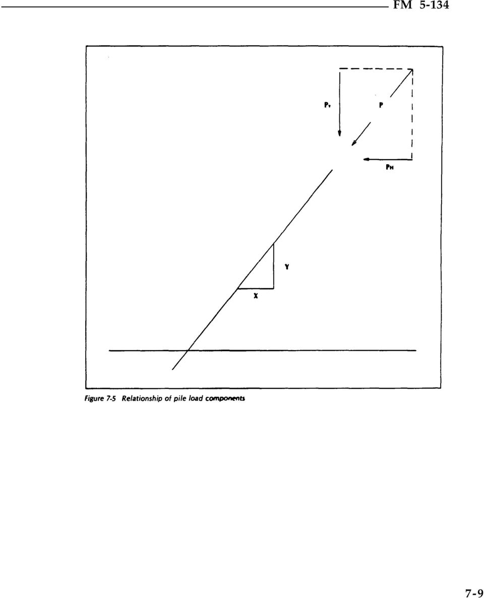
7 P a = axial component of pile load where: c x = resultant of vertical loads on a pile group n = number piles = summation of all moments about the center of gravity of pile group at the level of pile fixity due to XV and (figure 7-4) = distance from center of gravity of pile group to pile for which P v is being calculated x = coefficient of horizontal batter y = coefficient of vertical batter = angle (in degrees) of the batter The horizontal component of axial loads on the batter pile is assumed to add to or resist the horizontal thrust depending upon the direction of batter. The horizontal load on any pile is the algebraic difference between the resultant horizontal load and the summation of the horizontal components of axial loads on the batter piles divided by the number of piles. I y = moment of inertia of pile group The relationship between the vertical and horizontal load components and resultant axial pile load is shown in figure 7-5. Calculate the horizontal and axial components as follows. The vertical, horizontal, and axial components (figure 7-4) may be represented by a force polygon (figure 7-6). The batter piles have reduced the magnitude of the total horizontal load from as follows. where P h = horizontal component of pile load These operations can be interpreted graphically or computed mathematically. After constructing the force diagram or computing the lateral loads and bending stresses on each pile, the loads are checked to determine if they are less than the allowable lateral resistance and bending stresses. 7-7

8 7=8 FM 5-134

9 7-9
10 7-10 FM 5-134

ALLOWABLE LOADS ON A SINGLE PILE
 C H A P T E R 5 ALLOWABLE LOADS ON A SINGLE PILE Section I. BASICS 5-1. Considerations. For safe, economical pile foundations in military construction, it is necessary to determine the allowable load capacity
Structural Axial, Shear and Bending Moments
 Structural Axial, Shear and Bending Moments Positive Internal Forces Acting Recall from mechanics of materials that the internal forces P (generic axial), V (shear) and M (moment) represent resultants
Copyright 2011 Casa Software Ltd. www.casaxps.com. Centre of Mass
 Centre of Mass A central theme in mathematical modelling is that of reducing complex problems to simpler, and hopefully, equivalent problems for which mathematical analysis is possible. The concept of
Lecture 8 : Coordinate Geometry. The coordinate plane The points on a line can be referenced if we choose an origin and a unit of 20
 Lecture 8 : Coordinate Geometry The coordinate plane The points on a line can be referenced if we choose an origin and a unit of 0 distance on the axis and give each point an identity on the corresponding
INTRODUCTION TO BEAMS
 CHAPTER Structural Steel Design LRFD Method INTRODUCTION TO BEAMS Third Edition A. J. Clark School of Engineering Department of Civil and Environmental Engineering Part II Structural Steel Design and Analysis
When the fluid velocity is zero, called the hydrostatic condition, the pressure variation is due only to the weight of the fluid.
 Fluid Statics When the fluid velocity is zero, called the hydrostatic condition, the pressure variation is due only to the weight of the fluid. Consider a small wedge of fluid at rest of size Δx, Δz, Δs
Statics of Structural Supports
 Statics of Structural Supports TYPES OF FORCES External Forces actions of other bodies on the structure under consideration. Internal Forces forces and couples exerted on a member or portion of the structure
m i: is the mass of each particle
 Center of Mass (CM): The center of mass is a point which locates the resultant mass of a system of particles or body. It can be within the object (like a human standing straight) or outside the object
Problem 1: Computation of Reactions. Problem 2: Computation of Reactions. Problem 3: Computation of Reactions
 Problem 1: Computation of Reactions Problem 2: Computation of Reactions Problem 3: Computation of Reactions Problem 4: Computation of forces and moments Problem 5: Bending Moment and Shear force Problem
Graphing Quadratic Functions
 Problem 1 The Parabola Examine the data in L 1 and L to the right. Let L 1 be the x- value and L be the y-values for a graph. 1. How are the x and y-values related? What pattern do you see? To enter the
Design of reinforced concrete columns. Type of columns. Failure of reinforced concrete columns. Short column. Long column
 Design of reinforced concrete columns Type of columns Failure of reinforced concrete columns Short column Column fails in concrete crushed and bursting. Outward pressure break horizontal ties and bend
Introduction to Beam. Area Moments of Inertia, Deflection, and Volumes of Beams
 Introduction to Beam Theory Area Moments of Inertia, Deflection, and Volumes of Beams Horizontal structural member used to support horizontal loads such as floors, roofs, and decks. Types of beam loads
REINFORCED CONCRETE. Reinforced Concrete Design. A Fundamental Approach - Fifth Edition. Walls are generally used to provide lateral support for:
 HANDOUT REINFORCED CONCRETE Reinforced Concrete Design A Fundamental Approach - Fifth Edition RETAINING WALLS Fifth Edition A. J. Clark School of Engineering Department of Civil and Environmental Engineering
MODULE E: BEAM-COLUMNS
 MODULE E: BEAM-COLUMNS This module of CIE 428 covers the following subjects P-M interaction formulas Moment amplification Web local buckling Braced and unbraced frames Members in braced frames Members
Module 2. Analysis of Statically Indeterminate Structures by the Matrix Force Method. Version 2 CE IIT, Kharagpur
 Module Analysis of Statically Indeterminate Structures by the Matrix Force Method esson 11 The Force Method of Analysis: Frames Instructional Objectives After reading this chapter the student will be able
1.2 GRAPHS OF EQUATIONS. Copyright Cengage Learning. All rights reserved.
 1.2 GRAPHS OF EQUATIONS Copyright Cengage Learning. All rights reserved. What You Should Learn Sketch graphs of equations. Find x- and y-intercepts of graphs of equations. Use symmetry to sketch graphs
Section 16: Neutral Axis and Parallel Axis Theorem 16-1
 Section 16: Neutral Axis and Parallel Axis Theorem 16-1 Geometry of deformation We will consider the deformation of an ideal, isotropic prismatic beam the cross section is symmetric about y-axis All parts
Bending Stress in Beams
 936-73-600 Bending Stress in Beams Derive a relationship for bending stress in a beam: Basic Assumptions:. Deflections are very small with respect to the depth of the beam. Plane sections before bending
Mechanical Principles
 Unit 4: Mechanical Principles Unit code: F/601/1450 QCF level: 5 Credit value: 15 OUTCOME 4 POWER TRANSMISSION TUTORIAL 2 BALANCING 4. Dynamics of rotating systems Single and multi-link mechanisms: slider
SOLID MECHANICS BALANCING TUTORIAL BALANCING OF ROTATING BODIES
 SOLID MECHANICS BALANCING TUTORIAL BALANCING OF ROTATING BODIES This work covers elements of the syllabus for the Edexcel module 21722P HNC/D Mechanical Principles OUTCOME 4. On completion of this tutorial
Module 5 (Lectures 17 to 19) MAT FOUNDATIONS
 MAT FOUNDATIONS") Module 5 (Lectures 17 to 19) MAT FOUNDATIONS Topics 17.1 INTRODUCTION Rectangular Combined Footing: Trapezoidal Combined Footings: Cantilever Footing: Mat foundation: 17.2 COMMON TYPES OF MAT FOUNDATIONS
Module 5 (Lectures 17 to 19) MAT FOUNDATIONS Topics 17.1 INTRODUCTION Rectangular Combined Footing: Trapezoidal Combined Footings: Cantilever Footing: Mat foundation: 17.2 COMMON TYPES OF MAT FOUNDATIONS
CASE HISTORY #2. APPLICATION: Piping Movement Survey using Permalign Laser Measurement System
 CASE HISTORY #2 APPLICATION: Piping Movement Survey using Permalign Laser Measurement System EQUIPMENT: Dresser-Clark Hot Gas Expander (Turbine), 60-inch Inlet Flange HISTORY: Piping support modifications
PLANE TRUSSES. Definitions
 Definitions PLANE TRUSSES A truss is one of the major types of engineering structures which provides a practical and economical solution for many engineering constructions, especially in the design of
Laterally Loaded Piles
 Laterally Loaded Piles 1 Soil Response Modelled by p-y Curves In order to properly analyze a laterally loaded pile foundation in soil/rock, a nonlinear relationship needs to be applied that provides soil
MECHANICS OF SOLIDS - BEAMS TUTORIAL 2 SHEAR FORCE AND BENDING MOMENTS IN BEAMS
 MECHANICS OF SOLIDS - BEAMS TUTORIAL 2 SHEAR FORCE AND BENDING MOMENTS IN BEAMS This is the second tutorial on bending of beams. You should judge your progress by completing the self assessment exercises.
Safe & Sound Bridge Terminology
 Safe & Sound Bridge Terminology Abutment A retaining wall supporting the ends of a bridge, and, in general, retaining or supporting the approach embankment. Approach The part of the bridge that carries
Mechanics lecture 7 Moment of a force, torque, equilibrium of a body
 G.1 EE1.el3 (EEE1023): Electronics III Mechanics lecture 7 Moment of a force, torque, equilibrium of a body Dr Philip Jackson http://www.ee.surrey.ac.uk/teaching/courses/ee1.el3/ G.2 Moments, torque and
Tower Cross Arm Numerical Analysis
 Chapter 7 Tower Cross Arm Numerical Analysis In this section the structural analysis of the test tower cross arm is done in Prokon and compared to a full finite element analysis using Ansys. This is done
Stresses in Beam (Basic Topics)
") Chapter 5 Stresses in Beam (Basic Topics) 5.1 Introduction Beam : loads acting transversely to the longitudinal axis the loads create shear forces and bending moments, stresses and strains due to V and
Chapter 5 Stresses in Beam (Basic Topics) 5.1 Introduction Beam : loads acting transversely to the longitudinal axis the loads create shear forces and bending moments, stresses and strains due to V and
ENGINEERING SCIENCE H1 OUTCOME 1 - TUTORIAL 3 BENDING MOMENTS EDEXCEL HNC/D ENGINEERING SCIENCE LEVEL 4 H1 FORMERLY UNIT 21718P
 ENGINEERING SCIENCE H1 OUTCOME 1 - TUTORIAL 3 BENDING MOMENTS EDEXCEL HNC/D ENGINEERING SCIENCE LEVEL 4 H1 FORMERLY UNIT 21718P This material is duplicated in the Mechanical Principles module H2 and those
Fric-3. force F k and the equation (4.2) may be used. The sense of F k is opposite
 may be used. The sense of F k is opposite") 4. FRICTION 4.1 Laws of friction. We know from experience that when two bodies tend to slide on each other a resisting force appears at their surface of contact which opposes their relative motion. The
4. FRICTION 4.1 Laws of friction. We know from experience that when two bodies tend to slide on each other a resisting force appears at their surface of contact which opposes their relative motion. The
Design of Steel Structures Prof. S.R.Satish Kumar and Prof. A.R.Santha Kumar. Fig. 7.21 some of the trusses that are used in steel bridges
 7.7 Truss bridges Fig. 7.21 some of the trusses that are used in steel bridges Truss Girders, lattice girders or open web girders are efficient and economical structural systems, since the members experience
METHODS FOR ACHIEVEMENT UNIFORM STRESSES DISTRIBUTION UNDER THE FOUNDATION
 International Journal of Civil Engineering and Technology (IJCIET) Volume 7, Issue 2, March-April 2016, pp. 45-66, Article ID: IJCIET_07_02_004 Available online at http://www.iaeme.com/ijciet/issues.asp?jtype=ijciet&vtype=7&itype=2
Optimising plate girder design
 Optimising plate girder design NSCC29 R. Abspoel 1 1 Division of structural engineering, Delft University of Technology, Delft, The Netherlands ABSTRACT: In the design of steel plate girders a high degree
EFFECTS ON NUMBER OF CABLES FOR MODAL ANALYSIS OF CABLE-STAYED BRIDGES
 EFFECTS ON NUMBER OF CABLES FOR MODAL ANALYSIS OF CABLE-STAYED BRIDGES Yang-Cheng Wang Associate Professor & Chairman Department of Civil Engineering Chinese Military Academy Feng-Shan 83000,Taiwan Republic
Optimum proportions for the design of suspension bridge
 Journal of Civil Engineering (IEB), 34 (1) (26) 1-14 Optimum proportions for the design of suspension bridge Tanvir Manzur and Alamgir Habib Department of Civil Engineering Bangladesh University of Engineering
3.2. Solving quadratic equations. Introduction. Prerequisites. Learning Outcomes. Learning Style
 Solving quadratic equations 3.2 Introduction A quadratic equation is one which can be written in the form ax 2 + bx + c = 0 where a, b and c are numbers and x is the unknown whose value(s) we wish to find.
NUMERICAL INVESTIGATION OF SEISMIC ISOLATION FOR SINGLE- TOWER CABLE STAYED BRIDGES
 13 th World Conference on Earthquake Engineering Vancouver, B.C., Canada August 1-6, 24 Paper No. 1552 NUMERICAL INVESTIGATION OF SEISMIC ISOLATION FOR SINGLE- TOWER CABLE STAYED BRIDGES Charles B. CHADWELL
How To Write An Analysis System For Bridge Test
 Study of Analysis System for Bridge Test Chen Ke, Lu Jian-Ming, Research Institute of Highway, 100088, Beijing, China (chenkezi@163.com, lujianming@263.net) Summary Analysis System for Bridge Test (Chinese
How to Design Helical Piles per the 2009 International Building Code
 ABSTRACT How to Design Helical Piles per the 2009 International Building Code by Darin Willis, P.E. 1 Helical piles and anchors have been used in construction applications for more than 150 years. The
ex) What is the component form of the vector shown in the picture above?
 What is the component form of the vector shown in the picture above?") Vectors A ector is a directed line segment, which has both a magnitude (length) and direction. A ector can be created using any two points in the plane, the direction of the ector is usually denoted by
Vectors A ector is a directed line segment, which has both a magnitude (length) and direction. A ector can be created using any two points in the plane, the direction of the ector is usually denoted by
3. KINEMATICS IN TWO DIMENSIONS; VECTORS.
 3. KINEMATICS IN TWO DIMENSIONS; VECTORS. Key words: Motion in Two Dimensions, Scalars, Vectors, Addition of Vectors by Graphical Methods, Tail to Tip Method, Parallelogram Method, Negative Vector, Vector
Solving Simultaneous Equations and Matrices
 Solving Simultaneous Equations and Matrices The following represents a systematic investigation for the steps used to solve two simultaneous linear equations in two unknowns. The motivation for considering
Introduction. Background
 Introduction Welcome to CFS, the comprehensive cold-formed steel component design software. The endless variety of shapes and sizes of cold-formed steel members, combined with the complex failure modes
Technical Notes 3B - Brick Masonry Section Properties May 1993
 Technical Notes 3B - Brick Masonry Section Properties May 1993 Abstract: This Technical Notes is a design aid for the Building Code Requirements for Masonry Structures (ACI 530/ASCE 5/TMS 402-92) and Specifications
METHOD OF STATEMENT FOR STATIC LOADING TEST
 Compression Test, METHOD OF STATEMENT FOR STATIC LOADING TEST Tension Test and Lateral Test According to the American Standards ASTM D1143 07, ASTM D3689 07, ASTM D3966 07 and Euro Codes EC7 Table of Contents
Parachute Jumping, Falling, and Landing David C. Arney, Barbra S. Melendez, Debra Schnelle 1
 Parachute Jumping, Falling, and Landing David C. Arney, Barbra S. Melendez, Debra Schnelle 1 Introduction It is extremely important that leaders of airborne units understand the safety, medical, and operational
Design Analysis and Review of Stresses at a Point
 Design Analysis and Review of Stresses at a Point Need for Design Analysis: To verify the design for safety of the structure and the users. To understand the results obtained in FEA, it is necessary to
Analysis of Stresses and Strains
 Chapter 7 Analysis of Stresses and Strains 7.1 Introduction axial load = P / A torsional load in circular shaft = T / I p bending moment and shear force in beam = M y / I = V Q / I b in this chapter, we
Vocabulary Words and Definitions for Algebra
 Name: Period: Vocabulary Words and s for Algebra Absolute Value Additive Inverse Algebraic Expression Ascending Order Associative Property Axis of Symmetry Base Binomial Coefficient Combine Like Terms
EQUATIONS and INEQUALITIES
 EQUATIONS and INEQUALITIES Linear Equations and Slope 1. Slope a. Calculate the slope of a line given two points b. Calculate the slope of a line parallel to a given line. c. Calculate the slope of a line
4.2 Free Body Diagrams
 CE297-FA09-Ch4 Page 1 Friday, September 18, 2009 12:11 AM Chapter 4: Equilibrium of Rigid Bodies A (rigid) body is said to in equilibrium if the vector sum of ALL forces and all their moments taken about
F1 Fuel Tank Surging; Model Validation
 F1 Fuel Tank Surging; Model Validation Luca Bottazzi and Giorgio Rossetti Ferrari F1 team, Maranello, Italy SYNOPSIS A Formula One (F1) car can carry more than 80 kg of fuel in its tank. This has a big
Mechanics of Materials. Chapter 4 Shear and Moment In Beams
 Mechanics of Materials Chapter 4 Shear and Moment In Beams 4.1 Introduction The term beam refers to a slender bar that carries transverse loading; that is, the applied force are perpendicular to the bar.
EXPLORING THE TRUE GEOMETRY OF THE INELASTIC INSTANTANEOUS CENTER METHOD FOR ECCENTRICALLY LOADED BOLT GROUPS
 EXPLORING THE TRUE GEOMETRY OF THE INELASTIC INSTANTANEOUS CENTER METHOD FOR ECCENTRICALLY LOADED BOLT GROUPS L.S. Muir, P.E., Cives Steel Company, The United States W.A. Thornton, P.E., PhD, Cives Steel
Universal Law of Gravitation
 Universal Law of Gravitation Law: Every body exerts a force of attraction on every other body. This force called, gravity, is relatively weak and decreases rapidly with the distance separating the bodies
Volumes of Revolution
 Mathematics Volumes of Revolution About this Lesson This lesson provides students with a physical method to visualize -dimensional solids and a specific procedure to sketch a solid of revolution. Students
FOUNDATION DESIGN. Instructional Materials Complementing FEMA 451, Design Examples
 FOUNDATION DESIGN Proportioning elements for: Transfer of seismic forces Strength and stiffness Shallow and deep foundations Elastic and plastic analysis Foundation Design 14-1 Load Path and Transfer to
v v ax v a x a v a v = = = Since F = ma, it follows that a = F/m. The mass of the arrow is unchanged, and ( )
") Week 3 homework IMPORTANT NOTE ABOUT WEBASSIGN: In the WebAssign versions of these problems, various details have been changed, so that the answers will come out differently. The method to find the solution
Week 3 homework IMPORTANT NOTE ABOUT WEBASSIGN: In the WebAssign versions of these problems, various details have been changed, so that the answers will come out differently. The method to find the solution
4B-2. 2. The stiffness of the floor and roof diaphragms. 3. The relative flexural and shear stiffness of the shear walls and of connections.
 Shear Walls Buildings that use shear walls as the lateral force-resisting system can be designed to provide a safe, serviceable, and economical solution for wind and earthquake resistance. Shear walls
Selecting and Sizing Ball Screw Drives
 Selecting and Sizing Ball Screw Drives Jeff G. Johnson, Product Engineer Thomson Industries, Inc. Wood Dale, IL 540-633-3549 www.thomsonlinear.com Thomson@thomsonlinear.com Fig 1: Ball screw drive is a
Steel joists and joist girders are
 THE STEEL CONFERENCE Hints on Using Joists Efficiently By Tim Holtermann, S.E., P.E.; Drew Potts, P.E.; Bob Sellers, P.E.; and Walt Worthley, P.E. Proper coordination between structural engineers and joist
Recitation #5. Understanding Shear Force and Bending Moment Diagrams
 Recitation #5 Understanding Shear Force and Bending Moment Diagrams Shear force and bending moment are examples of interanl forces that are induced in a structure when loads are applied to that structure.
Deflections. Question: What are Structural Deflections?
 Question: What are Structural Deflections? Answer: The deformations or movements of a structure and its components, such as beams and trusses, from their original positions. It is as important for the
Figure 1.1 Vector A and Vector F
 CHAPTER I VECTOR QUANTITIES Quantities are anything which can be measured, and stated with number. Quantities in physics are divided into two types; scalar and vector quantities. Scalar quantities have
Overhang Bracket Loading. Deck Issues: Design Perspective
 Deck Issues: Design Perspective Overhang Bracket Loading Deck overhangs and screed rails are generally supported on cantilever brackets during the deck pour These brackets produce an overturning couple
CHAPTER 1 Linear Equations
 CHAPTER 1 Linear Equations 1.1. Lines The rectangular coordinate system is also called the Cartesian plane. It is formed by two real number lines, the horizontal axis or x-axis, and the vertical axis or
Algebra I Vocabulary Cards
 Algebra I Vocabulary Cards Table of Contents Expressions and Operations Natural Numbers Whole Numbers Integers Rational Numbers Irrational Numbers Real Numbers Absolute Value Order of Operations Expression
is the degree of the polynomial and is the leading coefficient.
 Property: T. Hrubik-Vulanovic e-mail: thrubik@kent.edu Content (in order sections were covered from the book): Chapter 6 Higher-Degree Polynomial Functions... 1 Section 6.1 Higher-Degree Polynomial Functions...
Chapter 11 Equilibrium
 11.1 The First Condition of Equilibrium The first condition of equilibrium deals with the forces that cause possible translations of a body. The simplest way to define the translational equilibrium of
Basic Understandings
 Activity: TEKS: Exploring Transformations Basic understandings. (5) Tools for geometric thinking. Techniques for working with spatial figures and their properties are essential to understanding underlying
Worked Example 2 (Version 1) Design of concrete cantilever retaining walls to resist earthquake loading for residential sites
 Design of concrete cantilever retaining walls to resist earthquake loading for residential sites") Worked Example 2 (Version 1) Design of concrete cantilever retaining walls to resist earthquake loading for residential sites Worked example to accompany MBIE Guidance on the seismic design of retaining
Worked Example 2 (Version 1) Design of concrete cantilever retaining walls to resist earthquake loading for residential sites Worked example to accompany MBIE Guidance on the seismic design of retaining
What does the number m in y = mx + b measure? To find out, suppose (x 1, y 1 ) and (x 2, y 2 ) are two points on the graph of y = mx + b.
 and (x 2, y 2 ) are two points on the graph of y = mx + b.") PRIMARY CONTENT MODULE Algebra - Linear Equations & Inequalities T-37/H-37 What does the number m in y = mx + b measure? To find out, suppose (x 1, y 1 ) and (x 2, y 2 ) are two points on the graph of
PRIMARY CONTENT MODULE Algebra - Linear Equations & Inequalities T-37/H-37 What does the number m in y = mx + b measure? To find out, suppose (x 1, y 1 ) and (x 2, y 2 ) are two points on the graph of
Number Sense and Operations
 Number Sense and Operations representing as they: 6.N.1 6.N.2 6.N.3 6.N.4 6.N.5 6.N.6 6.N.7 6.N.8 6.N.9 6.N.10 6.N.11 6.N.12 6.N.13. 6.N.14 6.N.15 Demonstrate an understanding of positive integer exponents
IV. ALGEBRAIC CONCEPTS
 IV. ALGEBRAIC CONCEPTS Algebra is the language of mathematics. Much of the observable world can be characterized as having patterned regularity where a change in one quantity results in changes in other
Torsion Tests. Subjects of interest
 Chapter 10 Torsion Tests Subjects of interest Introduction/Objectives Mechanical properties in torsion Torsional stresses for large plastic strains Type of torsion failures Torsion test vs.tension test
Module 8 Lesson 4: Applications of Vectors
 Module 8 Lesson 4: Applications of Vectors So now that you have learned the basic skills necessary to understand and operate with vectors, in this lesson, we will look at how to solve real world problems
Steel Design Guide Series. Column Base Plates
 Steel Design Guide Series Column Base Plates Steel Design Guide Series Column Base Plates Design of Column Base Plates John T. DeWolf Professor of Civil Engineering University of Connecticut Storrs, Connecticut
DESIGN SPECIFICATIONS FOR HIGHWAY BRIDGES PART V SEISMIC DESIGN
 DESIGN SPECIFICATIONS FOR HIGHWAY BRIDGES PART V SEISMIC DESIGN MARCH 2002 CONTENTS Chapter 1 General... 1 1.1 Scope... 1 1.2 Definition of Terms... 1 Chapter 2 Basic Principles for Seismic Design... 4
Example SECTION 13-1. X-AXIS - the horizontal number line. Y-AXIS - the vertical number line ORIGIN - the point where the x-axis and y-axis cross
 CHAPTER 13 SECTION 13-1 Geometry and Algebra The Distance Formula COORDINATE PLANE consists of two perpendicular number lines, dividing the plane into four regions called quadrants X-AXIS - the horizontal
FRICTION, WORK, AND THE INCLINED PLANE
 FRICTION, WORK, AND THE INCLINED PLANE Objective: To measure the coefficient of static and inetic friction between a bloc and an inclined plane and to examine the relationship between the plane s angle
A MATTER OF STABILITY AND TRIM By Samuel Halpern
 A MATTER OF STABILITY AND TRIM By Samuel Halpern INTRODUCTION This short paper deals with the location of Titanic s Center of Buoyancy (B), Center of Gravity (G) and Metacenter Height (M) on the night
Long-term serviceability of the structure Minimal maintenance requirements Economical construction Improved aesthetics and safety considerations
 Design Step 7.1 INTEGRAL ABUTMENT DESIGN General considerations and common practices Integral abutments are used to eliminate expansion joints at the end of a bridge. They often result in Jointless Bridges
Shear Forces and Bending Moments
 Chapter 4 Shear Forces and Bending Moments 4.1 Introduction Consider a beam subjected to transverse loads as shown in figure, the deflections occur in the plane same as the loading plane, is called the
Using the Quadrant. Protractor. Eye Piece. You can measure angles of incline from 0º ( horizontal ) to 90º (vertical ). Ignore measurements >90º.
 to 90º (vertical ). Ignore measurements >90º.") Using the Quadrant Eye Piece Protractor Handle You can measure angles of incline from 0º ( horizontal ) to 90º (vertical ). Ignore measurements 90º. Plumb Bob ø
Using the Quadrant Eye Piece Protractor Handle You can measure angles of incline from 0º ( horizontal ) to 90º (vertical ). Ignore measurements 90º. Plumb Bob ø
Shear Center in Thin-Walled Beams Lab
 Shear Center in Thin-Walled Beams Lab Shear flow is developed in beams with thin-walled cross sections shear flow (q sx ): shear force per unit length along cross section q sx =τ sx t behaves much like
12.510 Introduction to Seismology Spring 2008
 MIT OpenCourseWare http://ocw.mit.edu 12.510 Introduction to Seismology Spring 2008 For information about citing these materials or our Terms of Use, visit: http://ocw.mit.edu/terms. 04/30/2008 Today s
with functions, expressions and equations which follow in units 3 and 4.
 Grade 8 Overview View unit yearlong overview here The unit design was created in line with the areas of focus for grade 8 Mathematics as identified by the Common Core State Standards and the PARCC Model
Introduction to LRFD, Loads and Loads Distribution
 Introduction to LRFD, Loads and Loads Distribution Thomas K. Saad, P.E. Federal Highway Administration Chicago, IL Evolution of Design Methodologies SLD Methodology: (f t ) D + (f t ) L 0.55F y, or 1.82(f
Physics 1A Lecture 10C
 Physics 1A Lecture 10C "If you neglect to recharge a battery, it dies. And if you run full speed ahead without stopping for water, you lose momentum to finish the race. --Oprah Winfrey Static Equilibrium
Design of pile foundations following Eurocode 7-Section 7
 Brussels, 18-20 February 2008 Dissemination of information workshop 1 Workshop Eurocodes: background and applications Brussels, 18-20 Februray 2008 Design of pile foundations following Eurocode 7-Section
CHAPTER FIVE. 5. Equations of Lines in R 3
 118 CHAPTER FIVE 5. Equations of Lines in R 3 In this chapter it is going to be very important to distinguish clearly between points and vectors. Frequently in the past the distinction has only been a
Year 12 Pure Mathematics. C1 Coordinate Geometry 1. Edexcel Examination Board (UK)
") Year 1 Pure Mathematics C1 Coordinate Geometry 1 Edexcel Examination Board (UK) Book used with this handout is Heinemann Modular Mathematics for Edexcel AS and A-Level, Core Mathematics 1 (004 edition).
Year 1 Pure Mathematics C1 Coordinate Geometry 1 Edexcel Examination Board (UK) Book used with this handout is Heinemann Modular Mathematics for Edexcel AS and A-Level, Core Mathematics 1 (004 edition).
Biggar High School Mathematics Department. National 5 Learning Intentions & Success Criteria: Assessing My Progress
 Biggar High School Mathematics Department National 5 Learning Intentions & Success Criteria: Assessing My Progress Expressions & Formulae Topic Learning Intention Success Criteria I understand this Approximation
AP Physics: Rotational Dynamics 2
 Name: Assignment Due Date: March 30, 2012 AP Physics: Rotational Dynamics 2 Problem A solid cylinder with mass M, radius R, and rotational inertia 1 2 MR2 rolls without slipping down the inclined plane
Algebra 1 2008. Academic Content Standards Grade Eight and Grade Nine Ohio. Grade Eight. Number, Number Sense and Operations Standard
 Academic Content Standards Grade Eight and Grade Nine Ohio Algebra 1 2008 Grade Eight STANDARDS Number, Number Sense and Operations Standard Number and Number Systems 1. Use scientific notation to express
1 of 7 9/5/2009 6:12 PM
 1 of 7 9/5/2009 6:12 PM Chapter 2 Homework Due: 9:00am on Tuesday, September 8, 2009 Note: To understand how points are awarded, read your instructor's Grading Policy. [Return to Standard Assignment View]
Chapter 18 Static Equilibrium
 Chapter 8 Static Equilibrium 8. Introduction Static Equilibrium... 8. Lever Law... Example 8. Lever Law... 4 8.3 Generalized Lever Law... 5 8.4 Worked Examples... 7 Example 8. Suspended Rod... 7 Example
Physics 9e/Cutnell. correlated to the. College Board AP Physics 1 Course Objectives
 Physics 9e/Cutnell correlated to the College Board AP Physics 1 Course Objectives Big Idea 1: Objects and systems have properties such as mass and charge. Systems may have internal structure. Enduring
Chapter 7 Substructure Design... 7.1-1 7.1 General Substructure Considerations...7.1-1 7.1.1 Foundation Design Process...7.1-1 7.1.
 Chapter 7 Contents Chapter 7 Substructure Design... 7.1-1 7.1 General Substructure Considerations...7.1-1 7.1.1 Foundation Design Process...7.1-1 7.1.2 Foundation Design Limit States...7.1-3 7.1.3 Seismic