2 ND GENERATION HONDA CRX Si SUNROOF REPAIR & CLEAN-UP
|
|
|
- Brett Willis
- 9 years ago
- Views:
Transcription
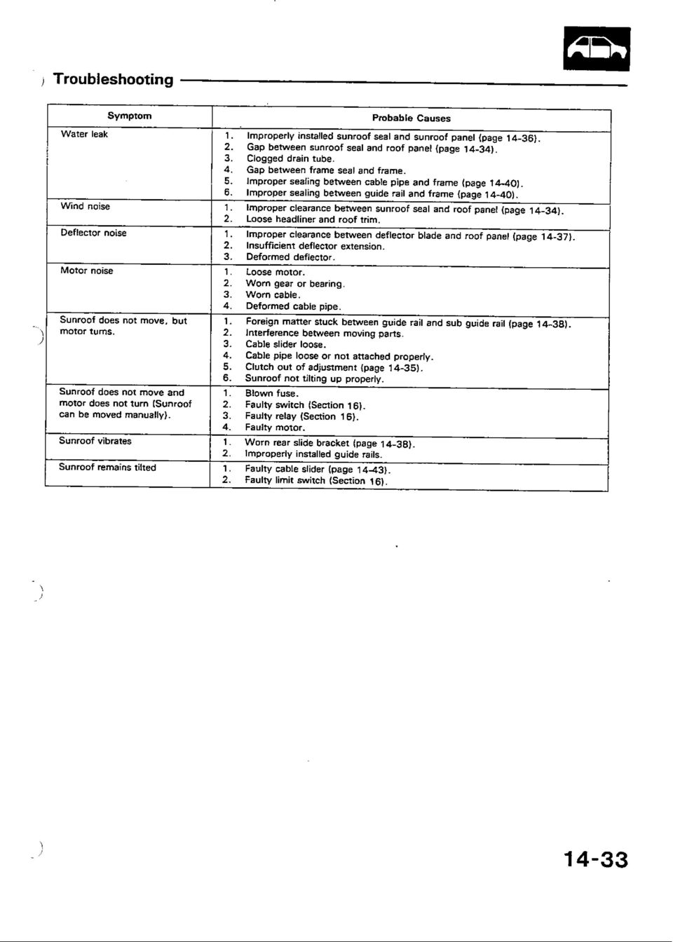
1 2 ND GENERATION HONDA CRX Si SUNROOF REPAIR & CLEAN-UP I recently purchased my 1989 CRX Si with 190,000 miles. The car is in excellent condition, considering the miles, and I got it from the original owner. Of course, any 13 year old car with this type of mileage will need some work. The previous owner informed me that the car had a leaking sunroof so I decided that I would refresh and clean the entire sunroof assembly. I figured that it was time for this procedure even if the sunroof was not the source of the leak. PARTS ORDERED I order all of my parts from or HONDA The list of parts I ordered was as follows: PART NAME HONDA PART NUMBER CONDITION (ON MY CAR) Front Stopper, Right SH2-000 Very worn (plastic part) Front Stopper, Left SH2-000 Very worn (plastic part) Slide Link, Right SB2-980 No noticeable wear (a metal part) Slide Link, Left SB2-980 No noticeable wear (a metal part) Slide Pins, Right & Left SB2-981 No noticeable wear (a metal part) Sunroof Panel Seal SH2-003 Very worn (rubber, of course) OTHER MATERIALS & TOOLS NEEDED 3M Black Weatherstrip Adhesive (the yellow works just as well but, please, ONLY buy 3M brand) White lithium or molybdenum sulfide grease Solvent for cleaning (I used 3M General Adhesive Cleaner; this stuff is VERY handy to have around) Rags or blue shop towels Screwdrivers Torx drivers Basic ratchet and metric socket set (8mm and 10mm) The inner sunroof frame seal is very expensive and I found that I did not need to replace the original. It was in excellent condition as it is not really exposed to the elements. In my opinion, if it needs replacing, just about any decent automotive supply shop (or JC Whitney) should carry a universal weatherstrip that is cheap and will work just as well. Don t waste your money on the Honda seal. If you can t take my word for it, just don t order one of them until you get a look at the one on your car. I ordered many of my parts before I knew anything about the sunroof assembly. I decided to just replace the parts that showed any wear and stuck the others away for future service. I will go over which parts showed the most wear throughout this procedure. GET STARTED I HAVE INCLUDED THE APPROPRIATE FACTORY SERVICE MANUAL INFORMATION FOR REFERENCE. The first thing to do is to study the sunroof section of the factory service manual. I looked this over several times until I had a decent understanding of what I thought needed to be done. Also take a close look at the interior diagrams so you can see how the panels are installed, decide on the best order of removal and be careful so that breakage of the panels tabs and clips is minimized. I hate that! INTERIOR PANEL REMOVAL Start by removing the necessary interior panels. I must say that the interior design is nothing short of excellent. I normally dread removing panels but they just came right out without any trouble. Remember to remove any screws or fasteners that might be holding the interior panels in place. Remove the interior pieces in the following order (See attachment *):

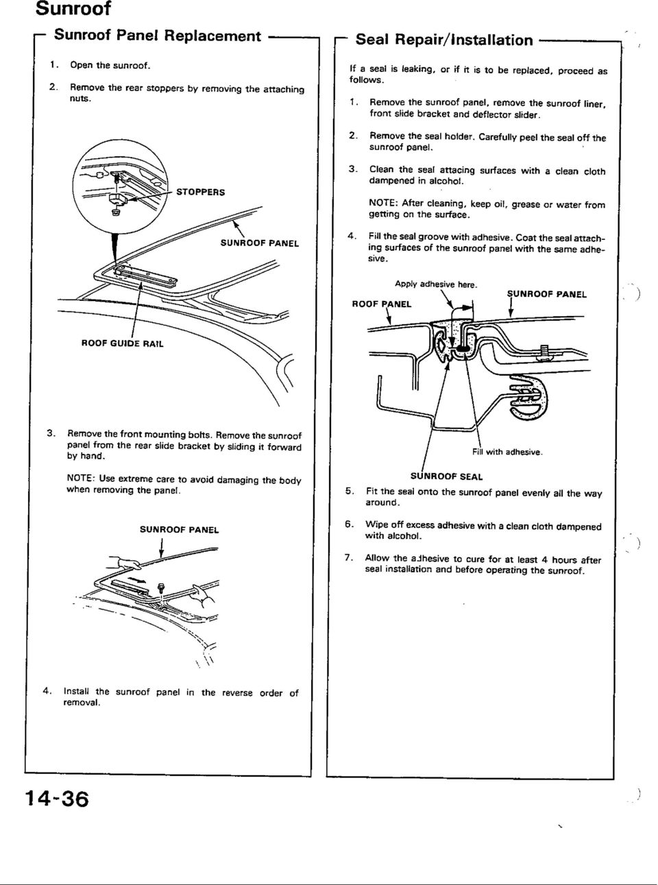
2 Door trim Interior dome light Rear roof trim panel Pull the rear quarter window panels loose at the upper front corner. There is no need to remove this entirely. Grab handle(s) Front pillar trim Sunvisors Rear view mirror Sunroof trim (around opening) Headliner Now that you have dropped the headliner, you have complete access to the sunroof tray assembly. BEFORE you start removing bolts to drop the assembly, remember to remove the sunroof panel. SUNROOF PANEL REMOVAL REAR STOP REMOVED PANEL REMOVED TRACK FORWARD Open the sunroof fully. Feel underneath the rear corners and you will find the rear plastic stops for the panel guide rails. Each stop is held in place by one (1) 8mm nut. A ratchet won t fit between the panel and the roof so just use a small 8mm open-ended wrench. Remove the rear stops; they just fall right off once the nut is removed. Now, go to the front corners of the panel and remove the 10mm bolts that fasten the front panel arms to the slide pins. There is one bolt for each side. The panel is now ready for removal. 2 bolts and 2 nuts are all that hold it in. Now, grasp the panel on the front and rear edges. Slide the panel toward the FRONT of the car and lift the front edge of the panel in one smooth, firm motion. Make sure to lift up on the front edge of the panel or you can easily scratch the paint on the roof! Don t jerk or twist the panel but BE FIRM. The panel will come out. Once you get it off the first time, further installation and removals will be much easier. Trust me on this! Now that you have the panel in your hands, remove the upholstery panel and inspect the metal for rust or deterioration. Sand, prime and paint if necessary. Stow away the panel for safekeeping. This might also be a good time to reconsider recovering that upholstery panel with some new vinyl! PANEL READY FOR SERVICE FRONT DRAIN TUBE REAR DRAIN TUBE
 8mm nut.")
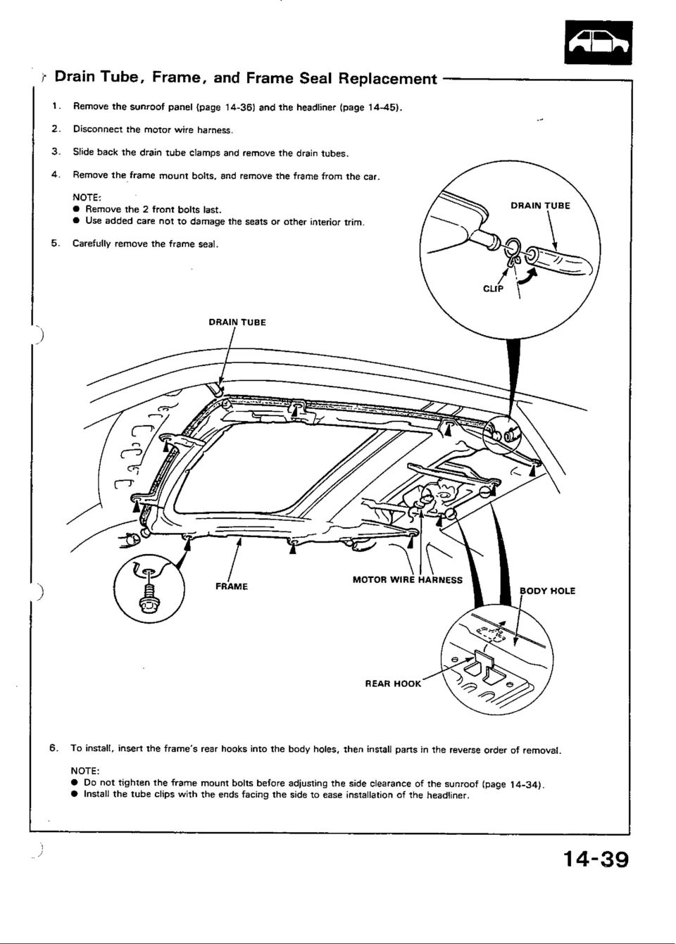
3 Once the sunroof panel is removed, turn on the car s ignition and actually close the sunroof assembly using the switch. SUNROOF PANEL PREPARATION & FIX-UP THE PANEL UPHOLSTERY REMOVED REMOVING SEAL HOLDDOWN With the sunroof panel on the workbench, flip it over so that the upholstery is exposed. Remove the 2 philips head screws and then CAREFULLY pry the upholstery panel from the metal panel. There is one plastic rivet in the middle of the upholstered panel that is hard to break loose without tearing the panel. Mine tore out so I will just put it back without it. Remove the panel seal hold downs by removing all of the philips head screws. Pull the old panel seal off and then clean up the seal contact surfaces of the panel. Remove all of the old adhesive. Spend as much time as you can stand on this part of the cleanup. The new panel seal you have purchased deserves the best chance to do its job! I used a razor blade and 3M General Adhesive Cleaner to help remove the old stuff. Lay the new panel seal next to the panel so that you are absolutely sure how it goes on. Double check yourself and be sure: once you glue it on it is a real PITA to do it over again. If you think getting the old adhesive off was bad; try it with freshly cured adhesive. I use only 3M Black Weatherstrip Adhesive. The cheaper brands are just that cheaper. Adhesives are one thing in which you truly get what you pay for. Apply adhesive to the channel of the seal and to the sealing surface of the panel. Use enough for good coverage but don t lay it on too thick or you will have a mess (too much is better than not enough, though). Follow the directions on the tube of adhesive and only apply the adhesive in small sections at a time. Don t try to glue on the whole seal at once. Let the adhesive dry until tacky and then install the seal. Get each section bonded before moving on to the next section. Take your time and work the seal so that the sunroof panel is fully seated in the channel of the rubber seal. This step alone took most of one evening for me. Prepare the sunroof panel before doing any tray work so that the adhesive can dry and cure before you put the panel into use. By the time you finish refurbishing the tray assembly, the panel will be ready to go! SUNROOF TRAY REMOVAL TRAY STILL BOLTED IN TRAY UNBOLTED & DROPPED TRAY READY FOR WORK Get inside the car and unplug the wiring harness from the sunroof motor. Also be sure that the plastic ties securing the wiring harness to the sunroof tray are loose. The motor harness will remain attached to the car body once the sunroof tray is removed. I used a small flat head

4 screwdriver to help me remove the little plastic wiring harness tie downs from their mounting positions. The tie downs clip into holes in the sheet metal. The last step before tray removal is to detach the drain tubes from each corner of the tray. The tubes are held in place by simple metal clamps that can be easily removed by hand. Slide the clamps down the tubes and then remove the tubes from the tray nipples. This may take a bit of twisting on the tubes to get them loose. BTW, I tossed the factory clamps and replaced them with sturdier worm drive band clamps. Inspect the tubes and use compressed air to clean them out. DO NOT remove the tubes from the chassis unless absolutely necessary. They don t just slide back in with ease. The rear tubes extend alongside the hatch (through the unibody cavity) and actually empty onto the ground at the rear corners of the car. The sunroof tray is attached to the roof via two bolts at the front, two at the rear and two on each side (10mm hex). Remove the side bolts first, followed by the rear bolts. Leave the front bolts in until you are ready to drop the tray. Note that the rear of the tray is suspended by hooks that keep it from falling on your head. Honda does things right. Now hold up the front of the tray with one hand while removing the front bolts with the other. The tray will now come out easily. Be careful not to rip the interior with the sharp corners of the tray assembly. I found it best to slide the seats as far back as possible and tilt the seat back to about a 45 degree angle. This allows you to lay in the seat and drop the sunroof tray right into your lap. SERVICING THE TRAY REMOVING WIND DEFLECTOR REAR LIFT MECHANISM REAR LIFT & SLIDE LINK Once the tray is out of the car, now is a good time to get all of your cleaning supplies together. I used 3M General Adhesive Cleaner (works great on oil and grease, too), WD40 and a bath of water and Castrol Super Clean to soak some really nasty stuff. My CRX had been spray painted at some point so there was lots of overspray in the sunroof mechanism. I decided that it would be best for me to just take the whole thing apart. That way, I was able to inspect most of the moving parts, clean them up and then re-lubricate in the necessary spots. I did leave the motor alone as it was working fine. You MUST have the roof mechanism in the CLOSED POSITION in order to disassemble the tray assembly. If you haven t already done this, STOP NOW. Hook the tray back up to the sunroof motor wiring harness and close the mechanism using the sunroof switch. This will allow access to all the necessary fasteners during assembly. Most steps below must be carried out on the left and right sides of the tray assembly. Refer to the Tray Assembly Photo. Each number below is reference in the photo so that parts can be more easily identified. 1) The wind deflector must be removed. This only requires one bolt per side (Philips head) and then it will just lift right out. My deflector was working fine and undamaged besides the weathered rubber strip. 2) Remove the plastic covers that cover the threaded shaft loopback. They are attached with one Philips fastener per side and are located on the inside near the roof opening. The loopback is where the excess length of the threaded shaft goes to when the roof is opened.

5 3) Remove the rear link assembly. This is a gold colored box at the rear of the tray (inset reference A ). There are 2 nuts (8mm hex) that hold the box to the tray, a philips machine screw that holds the box to the chrome rear lift mechanism (inset reference B ) and a philips head machine screw that holds the plastic lever to the chromed rear lift mechanism. Two 8mm nuts also hold down the edge of the rear lift mechanism. 4) Remove the rear most fastener for the aluminum tracks. This is a Philips/8mm hex machine screw. This fastener also holds the threaded shaft in place on the track. 5) In order to remove the aluminum guide track, two fasteners must be removed from the underside of the tray (8mm hex nuts). Once this is done, the track may be removed by pulling it free and sliding it off of the threaded shaft towards the front of the tray. This motion will also remove the sliding link & slide pin assembly (inset reference C ). 6) Once the track is removed, the front mount of the rear lift link assembly will be loose. It is sandwiched between the tray and the track. This can be done with the removal of one hex nut (8mm). 7) Remove the plastic sliding link guides from the tray. They are held in place by only one 8mm nut. The front plastic link guides are a high wear item and should be replaced. The guides on my car were severely distorted. These guides allow adjustment of the drop that the sunroof sliding link is allowed so that the roof panel will fall flush with the roof line. Once the tray was disassembled, I began cleaning all of the components and removing all traces of the old grease and grime. Inspect the threaded shaft to make sure it is not losing its threads or that the plastic is not losing its integrity. Inspect all of the movable parts for wear. My slide links and pins looked just as good as the new ones that I had on hand to compare with them. As I said above, the only really worn parts I found were the front plastic link guides that reside underneath the front of the aluminum track. Finally, inspect the tray itself. Pay careful attention to where the drain tubes hook up. My tray was in great shape so I cleaned it up for the next stage of the project. The next step is to lubricate all of the necessary parts and then reassemble. I used a basic white lithium grease making sure not to use too much in any one spot. I greased all of the moving parts and also coated the threaded shaft. TRAY REASSEMBLY THE FINISHED PRODUCT NICE AND SHINY! BEFORE DISASSEMBLY As they say, reassembly is the reverse of removal. Hopefully you paid close attention to the disassembly and didn t wait too long before trying to put everything back together. Be sure to use adhesive to glue down the inner tray seal. Use adhesive or other water-proof material to seal up the bottom fasteners where the aluminum track studs protrude through the tray. This is a source of potential leaks. DO NOT neglect to seal up the area where the threaded shaft tubes enter the tray area from the motor. I did this the first time around and ended up with a nice steady drip just above the driver s seat which required a week of garage time to dry out.

6 I used a type of rubberized adhesive tape that is used in the glass industry. I believe it is referred to as dum-dum tape. The stuff is like silly putty and sticks to anything. It works great for sealing the areas of the tray that I have just mentioned. TRAY INSTALLATION & PANEL ALIGNMENT INSTALLED PANEL TRACKS FRONT PANEL ARM At this point, it is time to start putting things back together. Put the tray in the car. Lay it in the front seats and then climb in underneath the tray and set it in your lap. Have the mounting bolts ready. Lift the tray into position and hook the rear of the tray in place using those nice hangers that Honda included. Then proceed to lift up the front of the tray and bolt it in place. Once the front is bolted up, the tray will not fall. Reinstall all tray fasteners but DO NOT tighten them down. Simply snug them up with just enough slack to allow movement of the tray from side to side and front to back. Hook the wiring harness to the sunroof motor. Next you must install the sunroof panel once again. USE THE SWITCH TO OPEN THE SUNROOF MECHANISM FULLY. Then, slide the rear guide arm (black plastic) to its rear-most position. The panel must be installed by inserting the rubber tang on the rear guide arm into the aluminum track that is installed on the underside of the sunroof panel. This means the panel will install with one movement by approaching from the front of the car and sliding the panel toward the rear of the car (the opposite of removal, of course). Once this is done, slide the panel toward the rear of the car until the front panel arms line up with the sliding links in the tray. Re-install the rear plastic stops on the panel. This must be done or the rear plastic guides will find their way out of the panel track when opening and closing the panel. Check the alignment of your sunroof by closing the panel with the switch. There is a SMALL amount of adjustment built into the mounting holes of the tray but I made most of my adjustments using the panel hardware. If the panel sits too low in the sunroof opening, use thin washers to space the front arm or aluminum tracks of the panel away from the panel itself. This will raise the panel back to height. See the second picture above. The rear corners can be lifted by inserting spacers on the rearmost stud that holds the aluminum track. The front corners can be lifted by using spacers under the front panel arm. If, by some chance, the sunroof sits too high after installation it can be lowered by inserting spacers INSIDE the car between the tray mounts and body mounting points. Make sure that the panel will move smoothly with no binding of the motor. Align the panel so that the panel weatherstrip is touching all side of the sunroof opening. Tight clearances between the panel and roof opening could tear up your new weatherstrip. Use caution and take your time. Good luck!

7

8

9
10

11

12
13

14

15
16

17

18

19

20

21
1958-64 WINDOW CHANNEL, WEATHERSTRIP & WHISKER STRIP REPLACEMENT FOR 2-DOOR SEDANS
 By Denny Williams Photos by Denny Williams 1958-64 WINDOW CHANNEL, WEATHERSTRIP & WHISKER STRIP REPLACEMENT FOR 2-DOOR SEDANS Denny Williams - Technical Writer Denny is first and foremost a dyed-in-thewool
INSTALL/REMOVAL INSTRUCTIONS: WINDOW LIFT MOTOR
 REMOVAL/INSTALL OF WINDOW LIFT MOTOR (742-273) Ford Expedition 1997 2002, Lincoln Navigator 1998 2002, Ford F-150 Super Crew Cab 2001 General Tech Tips: Use painter s tape rather than duct tape to secure
FRONT BUMPER INSTALLATION INSTRUCTIONS 2007-2011 DODGE / MERCEDES SPRINTER
 Aluminess Products Inc 9402 Wheatlands Ct. #A Santee, CA 92071 619-449-9930 FRONT BUMPER INSTALLATION INSTRUCTIONS 2007-2011 DODGE / MERCEDES SPRINTER Please read before beginning Stainless steel hardware
2002 2005 Mini Cooper S Grille Install Instructions
 2002 2005 Mini Cooper S Grille Install Instructions Lower Front Grille BEFORE AFTER Package Contents 1 perforated grille (Stiletto, RAZR, or Monster) 6 Zip Tie Mounting Pads 1 is for the temp. sensor 5
INSTALL/REMOVAL INSTRUCTIONS: WINDOW REGULATOR
 REMOVAL/INSTALL OF WINDOW REGULATOR (741-306) Honda Accord 2003 07 General Tech Tips: Use painter s tape rather than duct tape to secure window. It will not damage paint or leave sticky residue. A plastic
MGB Chrome Bumper Conversion
 MGB Chrome Bumper Conversion Installation Instructions For 1974 1/2-1980 MGB This kit requires cutting, welding, and painting. Professional installation recommended. Note: Every MGB body is slightly different
Convertible Top Hydraulic Cylinder Removal Manual for W124 E-Class Convertibles 1993-1995 Models 300CE (1993) and E320 (1994-1995)
 and E320 (1994-1995)") Convertible Top Hydraulic Cylinder Removal Manual for W124 E-Class Convertibles 1993-1995 Models 300CE (1993) and E320 (1994-1995) Written by Samit Ghosh with picture material from vexed of benzworld.org
Convertible Top Hydraulic Cylinder Removal Manual for W124 E-Class Convertibles 1993-1995 Models 300CE (1993) and E320 (1994-1995) Written by Samit Ghosh with picture material from vexed of benzworld.org
www.cornholesupplies.com
 www.cornholesupplies.com How To Build Regulation Cornhole Boards Home of the Original Cornhole Bags and Boards Supply List: 1-4' X 8' Piece of Plywood (pre sanded) 4-2" X 4" X 8' Studs (2 by 4s make sure
FRONT WINDSHIELD SEAL INSTALLATION
 FRONT WINDSHIELD SEAL INSTALLATION Tech Article From Newsletter 16.1-1st Quarter of 2010 Replacing your Front Windshield Seal ISN T AS HARD AS YOU MAY THINK! Recently, we retooled our front window seal
INSTALL/REMOVAL INSTRUCTIONS: WINDOW REGULATOR
 REMOVAL/INSTALL OF WINDOW REGULATOR (748-547) Chrysler 300 2005 10, Dodge Magnum 2005 08, Dodge Charger 2006 09 General Tech Tips: Use painter s tape rather than duct tape to secure window. It will not
C5 Sound Deadening & Insulation Kit Interior Removal & Installation Instructions
 C5 Sound Deadening & Insulation Kit Interior Removal & Installation Instructions Ok, let's start with taking the radio bezel dash area off first. Here is what the OEM radio looks like... First you flip
Figure 2 The fan and shroud also needs to be removed for access to the four a/c compressor bolts and removal of the compressor from the top.
 Here are some pictures to show what s required when replacing the A/C compressor, expansion valve and receiver/drier on a 2001 Volvo V70. Even if you don t replace these A/C parts these pictures can help
Overview PARTS LIST. B. Lever mounting base C. Flush handle assembly D. Grey/Blue float stop E. Grey float (Full Flush) F. Flush valve washer
 F. Flush valve washer") Overview READ ENTIRE INSTRUCTIONS BEFORE STARTING INSTALLATION PARTS LIST A. Flush valve B. Lever mounting base C. Flush handle assembly D. Grey/Blue float stop E. Grey float (Full Flush) F. Flush valve
Overview READ ENTIRE INSTRUCTIONS BEFORE STARTING INSTALLATION PARTS LIST A. Flush valve B. Lever mounting base C. Flush handle assembly D. Grey/Blue float stop E. Grey float (Full Flush) F. Flush valve
Solstice/Sky Water Pump Replacement
 Solstice/Sky Water Pump Replacement The water pump on the Solstice/Sky is starting to need replacement on some vehicles. This guide will help in replacing the water pump while the engine is still in the
New method, replacement of window and window lift, front door
 SERVICE INFORMATION Number: 831-1646 Year: 1996 Month: Market: FEBRUARI ALL New method, replacement of window and window lift, front door Cars concerned All Saab 900 M94- Background A new method of removing
INSTALLATION INSTRUCTIONS FOR 2006-2009 VW MK5
 CI100018 INSTALLATION INSTRUCTIONS FOR 2006-2009 VW MK5 Rabbit, Jetta 2.5L These instructions are applicable to vehicles equipped with either manual or automatic transmissions Thank you for choosing to
Time needed: ~3h for lid replacement only. Add 1h for operation harness in lid and ~2h more for installing drive unit and cable harness in trunk.
 DIY for replacing trunk lid and/or retrofitting electrical operation of trunk lid. This document is meant to be a support and give advice on the procedure but I will take no responsibility for any damage
Navico-Northstar 2kW JRC Radar Package, Scanner Cable Removal and Replacement
 Navico-Northstar 2kW JRC Radar Package, Scanner Cable Removal and Replacement This work instruction describes the methods and means for which to remove and reinstall optional scanner cable configurations
Installation instructions, accessories - Handsfree for cellular phone, system B, entry level
 XC90 Section Group Weight(Kg/Pounds) Year Month 3 39 0.5/1.1 2006 07 XC90 2003, XC90 2004 IMG-249663 Page 1 of 18 Required tools A0000162 A0000163 IMG-239664 M0000232 IMG-253123 IMG-252223 Page 2 of 18
Juice Box Stages 1&2 135&335 Installation Guide 5/10/08
 Tools Required: 8mm socket or nut driver Small flat head screwdriver Electrical tape, masking tape, or shrink tube Pep talk: Although the install looks daunting at first, once you get the learning curve
Contents. Front Derailleurs... 2. Part One - Planning... 2 I. Objectives... 2 II. Materials Needed... 2 III. Setting...2 IV. Evaluation...
 Contents... 2 Part One - Planning... 2 I. Objectives... 2 II. Materials Needed... 2 III. Setting...2 IV. Evaluation... 2 Part Two - Activity Instructions... 3 Steps to Adjusting and Replacing... 3 Disassemble...
TUTORIAL. REbUILdING. front CALIpER O-RING CONVERSION CORVETTE 1965-82. Part #: HT-1
 Part #: HT-1 1965-82 CORVETTE O-RING CONVERSION front CALIpER REbUILdING TUTORIAL Choosing a Brake Caliper Rebuild Kit Standard Lip Seals vs. O-Ring Seals Lip seal design seals are used on 1965-1982 Corvette
Manual for GlobePharma Mini-Press II Rotary Tablet Press
 1 of 13 Preparing the Rotary Press 1. Make sure the rotary press is unplugged. 2. Open the bottom cabinet of the rotary press and take out the grey tool kit, and the beige box of punches and dies. 3. Take
Modular Locomotive System Instruction Manual for HBK8 George Body Kit
 Modular Locomotive System Instruction Manual for HBK8 George Body Kit Roundhouse Engineering Co. Ltd. Units 6-10 Churchill Business Park. Churchill Road, Wheatley. Doncaster. DN1 2TF. England. Tel. 01302
Power Window/Power Lock Installation. To begin with you will need all the parts listed below:
 Power Window/Power Lock Installation To begin with you will need all the parts listed below: From Donor Fiero: Fiero power window regulators Power window motors (Generic GM type part) -motors are riveted
RULE # 1 is DON T mess with things that you don t know anything about! (Take them to a pro & pay them to fix it)
") OK there seems to be a LOT of problems noted on KatRiders having to do with CARBS, so I thought I d write out sort of a checklist of things to help folks. RULE # 1 is DON T mess with things that you don
OK there seems to be a LOT of problems noted on KatRiders having to do with CARBS, so I thought I d write out sort of a checklist of things to help folks. RULE # 1 is DON T mess with things that you don
Installation Instructions Avalanche XUV Cap IMPORTANT! IMPORTANT!
 Installation Instructions Avalanche XUV Cap IMPORTANT! Read all instructions carefully before commencing any work. Always wear safety equipment. Some installation steps will require two or more installers.
5 Mechanisms and accessories
 5 Mechanisms and accessories 51A SIDE OPENING ELEMENT MECHANISMS 52A NON-SIDE OPENING ELEMENT MECHANISMS 54A WINDOWS 55A EXTERIOR PROTECTION 56A EXTERIOR EQUIPMENT 57A INTERIOR EQUIPMENT X79 NOVEMBER 2009
AWE Tuning Air/Air Intercooler Kit for 2000-04 Audi 2.7T
 AWE Tuning Air/Air Intercooler Kit for 2000-04 Audi 2.7T Congratulations on your purchase of the AWE Tuning Intercoolers for your 2.7T Audi. Hundreds of hours of design and operational testing were spent
OWNER S MANUAL Table Tennis Table Patent Pending
 OWNER S MANUAL Table Tennis Table Patent Pending Be sure to write your model number and serial number here for future reference. You can find these numbers printed on the bottom of the table. MODEL # T8179
Installation instruction do88 Intercooler for Volvo S40 / V50 / C30
 Installation instruction do88 Intercooler for Volvo S40 / V50 / C30 This instruction shows how to replace the OEM intercooler with our performance intercooler. 2. 3. 1. 4. 5. Part number: ICM-170 6. At
AXLE SHAFTS - FRONT. 1998 Pontiac Bonneville MODEL IDENTIFICATION DESCRIPTION & OPERATION TROUBLE SHOOTING REMOVAL & INSTALLATION
 AXLE SHAFTS - FRONT 1998 Pontiac Bonneville 1998-99 DRIVE AXLES FWD Axle Shafts - Cars - "C", "G" & "H" Bodies GM Aurora, Bonneville, Eighty Eight, LeSabre, LSS, Park Avenue, Regency, Riviera MODEL IDENTIFICATION
MGB Seat Renovation. Since the vast majority of MGBs are 1970 and later models, we will elaborate on the repair of 1970 and later seats.
 MGB Seat Renovation A properly restored MGB deserves decent seats. Why is it when you look at a typically restored MG, the body looks great, but often when you peer in through the driver s window, the
BMW E46 Convertible Bow Cylinder replacement guide
 BMW E46 Convertible Bow Cylinder replacement guide There is nothing better than a BMW convertible, until uh oh... what s that? You find a wet spot on the cover or rear deck. You clean it and it comes back.
Written By: Walter Galan
 ipad 2 GSM LCD Replacement Replace the LCD in your ipad 2 GSM. Written By: Walter Galan INTRODUCTION Use this guide to replace a broken LCD. TOOLS: iopener (1) Phillips #00 Screwdriver (1) Plastic Opening
Tool And Material Checklist
 HOW - TO CV JOINTS CV JOINTS Tool And Material Checklist Screwdriver Metal Shears Breaker Bar or Torque Wrench Assorted Wrenches Wire Evaporating Spray Solvent Pusher Tool Vise Snap Ring or Duckbill Pliers
www.odometergears.com Ford Ranger and Mazda Pickup Odometer Worm Gear Replacement
 www.odometergears.com Ford Ranger and Mazda Pickup Odometer Worm Gear Replacement http://www.therangerstation.com/magazine/fall2008/odometer_worm_gear.htm ****************************************************************************************************
TABLE OF CONTENTS. I. TROUBLESHOOTING... 2 - Section 1.01: Common Problems/Solutions... 2
 BAL Accu-Slide System I. Table of Contents TABLE OF CONTENTS I. TROUBLESHOOTING... 2 - Section 1.01: Common Problems/Solutions... 2 II. GETTING STARTED... 5 - Section 2.01: Tools You Will Need... 5 - Section
COOPER S PULLEY UPGRADE KIT INSTALLATION INSTRUCTIONS PART NUMBER NME5011
 COOPER S PULLEY UPGRADE KIT INSTALLATION INSTRUCTIONS PART NUMBER NME5011 Below are instructions for the Mini Mania Pulley Upgrade Kit, Part Number NME5011. Please take all necessary precautions for working
TUTORIAL. REbUILdING. REAR CALIpER O-RING CONVERSION CORVETTE 1965-82. Part #: HT-2
 Part #: HT-2 1965-82 CORVETTE O-RING CONVERSION REAR CALIpER REbUILdING TUTORIAL Choosing a Brake Caliper Rebuild Kit Standard Lip Seals vs. O-Ring Seals Lip seal design seals are used on 1965-1982 Corvette
TOYOTA Tundra 2007 - BACK-UP CAMERA SYSTEM Preparation
 Preparation Part Number(s): PT233-34070, PT923-35070-11, PT923-35070-43 NOTE: Part number of this accessory may not be the same as part number shown. Back Up Monitor Kit Contents PT923-35070-11 / PT923-35070-43
HP Laser Jet 4200/4240/4250/4300/4350 Swing Plate
 HP Laser Jet 4200/4240/4250/4300/4350 Swing Plate 1 Swing Plate Assembly-RM1-0043 1 Swing Plate Kit-5851-2766 (RM1-0043 plus RM1-1091 gear) CAUTION: Fuser may be hot. Turn off printer, unplug it and allow
Premier & Deluxe 3-Season Room Sliding Glass Door
 DTSSGD-11 Premier & Deluxe 3-Season Room Sliding Glass Door Installation Instructions Screen Door Seal Left Side Track Top Track Assembly Right Side Track Right Side Trim Sliding Glass Door Sliding Screen
R O A D M A S T E R, I N C.
 R O A D M A S T E R, I N C. 6 28 1 2 "ā 1 2 " 4 8 ITEM QTY NAME PART # 1...4...1/2 x 1 1/4 BOLTS... 350094-00 2...4...1/2 LOCK WASHER... 350309-00 3...4...1/2 HEX NUT... 350258-00 4...2...SPACER PLATE...
Drive shaft, servicing
 Volkswagen Passat B6 - Drive shaft, servicing Стр. 1 из 41 40-7 Drive shaft, servicing Drive shafts, overview I - Assembly overview: Drive axle with CV joint VL100 40-7, Drive axle with CV joint VL100,
Installation Instructions
 Installation Instructions READ BEFORE INSTALLING UNIT For Low Profile Window Air Conditioner INSTALLATION WARNINGS AND CAUTION Carefully read the installation manual before beginning. Follow each step
Retrofit Instructions Installing a Sport Heated Steering Wheel - Leather, Multifunction BMW X5, E53, 2001 2006
 Retrofit Instructions Installing a Sport Heated Steering Wheel - Leather, Multifunction BMW X5, E53, 2001 2006 Disclaimer: This set of instructions is simply a guide on how I installed my own heated steering
INSTALLATION INSTRUCTIONS
 INSTALLATION INSTRUCTIONS Accessory Application Publications No. AII23628 2003 PILOT Issue Date MAY 2002 PARTS LIST Security System Kit (sold separately): P/N 08E51-S84-100 2 Remote controls Attachment
majestic install ation guide barcelona three sided enclosure 24mm surface mounted wall channels and underframe to base
 majestic install ation guide barcelona three sided enclosure 24mm surface mounted wall channels and underframe to base These Instructions are for a left and right handed unit. The diagrams show a left
TOYOTA TUNDRA 2015 Billet Grille w/led DRL
 TOYOTA TUNDRA 2015 Billet Grille w/led DRL Part Number: 00016-34088 Accessory Code: BG3000 Conflicts Models 1794 and Platinum Kit Contents Item # Quantity Reqd. Description 1 2 LED DRL 2 1 Driver Box 3
STEADYfast Stabilizer Installation Notes Fifth Wheel and Travel Trailers 11/23/13
 STEADYfast Stabilizer Installation Notes Fifth Wheel and Travel Trailers 11/23/13 (See Supplemental Instructions for trailers with heavy duty round footplates and/or Power Leveling Systems) PHONE SUPPORT
INSTALLATION INSTRUCTIONS
 Rear Vision System Tailgate Handle Camera Mirror Display 2004-2014 Ford F-150 and 2008-2015 Ford Super Duty (Kit part numbers 9002-9521) Kit Contents: Mirror Tailgate Handle with camera and harness Interior
Installing RNS-E SAT NAV for Audi A4
 As one of the major options on the A4 you can get a DVD Satellite Navigation System call the RNS-E. With the help of ebay these sat nav systems are now available to by at a rough cost of 650 plus the cost
Front brakes (FN- 3), servicing
, servicing") j a t Front brakes (FN- 3), servicing 46-1 Front brakes, servicing Note: Install complete repair kit. After replacing brake pads and before moving vehicle, depress brake pedal several times firmly to properly
j a t Front brakes (FN- 3), servicing 46-1 Front brakes, servicing Note: Install complete repair kit. After replacing brake pads and before moving vehicle, depress brake pedal several times firmly to properly
758 Heavy-duty Ratchet Guy Wire Cutter
 INSTRUCTION MANUAL 758 Heavy-duty Ratchet Guy Wire Cutter Read and understand all of the instructions and safety information in this manual before operating or servicing this tool. Register this product
Black Wolf POCKET BILLIARD TABLE INSTALLATION MANUAL. SERVICE DEPARTMENT P.O. BOX 68 BRISTOL, WI 53104
 Black Wolf TM POCKET BILLIARD TABLE INSTALLATION MANUAL www.brunswickbilliards.com SERVICE DEPARTMENT P.O. BOX 68 BRISTOL, WI 53104 51-905710-000 SEPTEMBER 2010 NOTE: Please use the instructions in this
Written By: Walter Galan
 ipad 2 GSM Rear Camera Replacement Replace the rear camera in your ipad 2 GSM. Written By: Walter Galan INTRODUCTION Use this guide to replace a broken rear camera. TOOLS: ifixit Opening Picks set of 6
1.8 CRANKSHAFT OIL SEALS
 SERIES 60 SERVICE MANUAL 1.8 CRANKSHAFT OIL SEALS An oil seal is fitted between each end of the crankshaft and the bores of the flywheel housing and gear case cover to retain the lubricating oil in the
INSTALL/REMOVAL INSTRUCTIONS: WINDOW REGULATOR
 REMOVAL/INSTALL OF WINDOW REGULATOR (741-644) Cadillac Escalade, Chevrolet Suburban, Chevrolet Tahoe, GMC Yukon, Chevrolet Silverado, GMC Sierra 2000 05 General Tech Tips: Use painter s tape rather than
Cable Drum Installation
 20 Cable Drum Installation COUNTERBALANCE None Shake the TorqueMaster spring tube gently to extend the winding shafts out about 5" on each side. For single spring applications, there will be no left hand
Installation Guide for the TJ LCG PRO Suspension System (Low Center of Gravity) Available 4 or 5
 Available 4 or 5") INSTALLATION GUIDE Installation Guide for the TJ LCG PRO Suspension System (Low Center of Gravity) Available 4 or 5 Take every precaution to make this installation a safe procedure. Make safety the number
INSTALLATION GUIDE Installation Guide for the TJ LCG PRO Suspension System (Low Center of Gravity) Available 4 or 5 Take every precaution to make this installation a safe procedure. Make safety the number
DETACHABLE WINDSHIELD AND DOCKING HARDWARE KIT
 -J00 REV. 00-- DETACHABLE WINDSHIELD AND DOCKING HARDWARE KIT GENERAL Kit Number -A, 0-, -, 0-, -, - 0, -0 Models These kits fit and later FXST, FXSTB, FXSTC, and and later FXDWG Harley-Davidson model
http://waterheatertimer.org/troubleshoot-rheem-tankless-water-heater.html
 http://waterheatertimer.org/troubleshoot-rheem-tankless-water-heater.html TECHNICAL SERVICE DEPARTMENT Removal, Cleaning, & Reinstallation of the Burner Assembly For models 74 & GT199 Required tools -
The Ford Model A Water Pump
 The Ford Model A Water Pump George Washington Chapter, Inc. 3903 Old Lee Highway Fairfax, VA 22030 1 Table of Contents Introduction/Specifications.. 3 1. Water Pump Inspection and Removal. 4 a. Removal..
Build Your Own Solar Car Teach build learn renewable Energy! Page 1 of 1
 Solar Car Teach build learn renewable Energy! Page 1 of 1 Background Not only is the sun a source of heat and light, it s a source of electricity too! Solar cells, also called photovoltaic cells, are used
BILLET HEADLAMP SHELL
 -J008 REV. 007-07- BILLET HEADLAMP SHELL GENERAL Kit Number 770-0 Models For model fitment information, please see the P&A Retail Catalog or the Parts and Accessories section of www.harleydavidson.com
Alfa Romeo 147 On board instruments installation guide
 Alfa Romeo 147 On board instruments installation guide Alfa Romeo 147 On board instruments installation guide This guide is describing how I installed oil temperature and oil pressure gauges to my Alfa
Wiper Motor Marinco 2.5. Installation Instructions
 Wiper Motor Marinco 2.5 Installation Instructions Wiper Motor Marinco-2.5 The Marinco 2.5 Wiper Motor Offers the Following Features: Fully sealed base and housing which allows installation in outdoor wet
Rebuild Instructions for 70001 and 70010 Transmission
 Rebuild Instructions for 70001 and 70010 Transmission Brinn, Incorporated 1615 Tech Drive Bay City, MI 48706 Telephone 989.686.8920 Fax 989.686.6520 www.brinninc.com Notice Read all instructions before
Tri-Homo Style Operation and Maintenance Instructions
 Tri-Homo Style Operation and Maintenance Instructions One Research Drive Stratford, CT 06615 (203) 375-0063 www.sonicmixing.com 1 Installation and Start-up Do not perform following adjustments without
Written By: Walter Galan
 ipad 2 GSM Front Panel Replacement Replace the front panel in your ipad 2 GSM. Written By: Walter Galan INTRODUCTION Note: this is a complete guide for replacing a plain front panel. If you have a Front
BUILDINGA 1/10 SCALE FLATBED TRAILER
 VOLUME 1, ISSUE 1 BUILDINGA 1/10 SCALE FLATBED TRAILER BUILT, DESIGNED & WRITTEN BY NATHAN MYERS MATERIALS: FEATURES: While the design was kept simple to allow anyone to be able to build their own trailer,
Char-Lynn Hydraulic Motor. Repair Information. 10 000 Series. October, 1997
 Char-Lynn Hydraulic Motor October, 1997 Repair Information Geroler Motor Two Speed 001 27 Retainer inside bore of valve plate bearingless motors only 4 15 16 3 6 35 Parts Drawing 25 2 2 1 19 17 36 40 47
SB-C-CTS/10TW3 SKU# 94552 2008 & Up Cadillac CTS/CTS-V
 INSTALLATION GUIDE for the SB-C-CTS/10TW3 SKU# 94552 2008 & Up Cadillac CTS/CTS-V If you choose to perform the installation yourself, it is absolutely vital that the Stealthbox be properly mounted to the
R O A D M A S T E R, I N C.
 R O A D M A S T E R, I N C. 11 4 9 28 1 2 "ā 1 2 " 10 7 13 Special tools needed: plastic pop rivet gun ITEM QTY NAME PART # 1...4... 1/2 x 1 1/4 BOLT... 350094-00 2...8... 1/2 LOCK WASHER... 350309-00
Rollator Cane and Brake Replacement SAFETY SUMMARY (CONTINUED)
") Rollator Cane and Replacement Assembly, Installation and Operating Instructions SAVE THESE INSTRUCTIONS NOTE: Check ALL parts for shipping damage. If shipping damage is noted, DO NOT use. Contact Carrier/Dealer
Rollator Cane and Replacement Assembly, Installation and Operating Instructions SAVE THESE INSTRUCTIONS NOTE: Check ALL parts for shipping damage. If shipping damage is noted, DO NOT use. Contact Carrier/Dealer
DIY CABINET REFACING INSTALLATION GUIDE
 DIY CABINET REFACING INSTALLATION GUIDE CABINET REFACING INSTALLATION Are you ready to reface your outdated cabinets? This guide will show you how to install your new Facelifters Cabinet Refacing Products
Installation Instructions 4508 4508S
 SYMPHONY Spread Lavatory Faucet with Speed Connect Drain Congratulations on purchasing your American Standard faucet with Speed Connect drain, a feature found only on American Standard faucets. Speed Connect
GENUINE PARTS INSTALLATION INSTRUCTIONS
 GENUINE PARTS INSTALLATION INSTRUCTIONS 1. DESCRIPTION: Auto-Dimming Mirror Kit with Compass and HomeLink 2. APPLICATION: Titan 3. PART NUMBER: 999L1 WS000 4. KIT CONTENTS: Item Qty Description Service
R O A D M A S T E R, I N C.
 R O A D M A S T E R, I N C. 11 7 6 1 2 10 13 8 ITEM QTY NAME PART # 1...2...1/2 x 5 1/2 BOLT...350108-00 2...4...1/2 x 1 3/4 BOLT...350096-00 3...6...1/2 LOCK WASHER...350309-00 4...6...1/2 HEX NUT...350258-00
Acer Aspire One AOA150-1570 Disassembly
 Acer Aspire One AOA150-1570 Disassembly Model The Acer Aspire One AOA150-1570 is the model with the 120GB hard drive (not the Flash drive) and 1GB RAM with Windows XP. Disassembly Beware of the ESD (ElectroStatic
Tired of wet feet & ruined carpets?
 Tired of wet feet & ruined carpets? If you re like us, you spend countless hours getting your car ready to head to the track or local car show on the weekends and the last thing you want is for your ride
16 April 2012 1032011-F 1994-2002 Dodge Adjustable Track bar with Relocation Bracket 1
 16 April 2012 1032011-F 1994-2002 Dodge Adjustable Track bar with Relocation Bracket 1 BD Adjustable Track Bar w/bracket Dodge 2500-3500 4WD Models 1994-2002 Dodge 1500 4WD Model 1994-2001 P/N# 1032011-F
A&A CORVETTE PERFORMANCE C6 BOOST & FUEL GAUGE INSTALLATION INSTRUCTIONS
 A&A CORVETTE PERFORMANCE C6 BOOST & FUEL GAUGE INSTALLATION INSTRUCTIONS 1. Check your gauges before you take them out of the packaging to make sure they are at 0 (zero) psi for both boost and fuel pressure.
How to Build a Poker Table
 How to Build a Poker Table www.pokertablematerials.com 10-Person Poker Table- 96 x 48 These are step by step instructions for building a poker table. The table will measure 48" x 96" and have a 4" wide
DYNA RIDER FOOTBOARD KIT
 -J0 REV. 0-0-0 DYNA RIDER FOOTBOARD KIT GENERAL Kit Number 000 Models For model fitment information, see the P&A Retail Catalog or the Parts and Accessories section of www.harley-davidson.com (English
GENUINE PARTS INSTALLATION INSTRUCTIONS
 GENUINE PARTS INSTALLATION INSTRUCTIONS DESCRIPTION: Illuminated Kick Plate APPLICATION: Rogue (2011) PART NUMBER: 999G6 GX010 KIT CONTENTS: Item A B C G H QTY 1 1 1 D 1 E 1 F 3 15 6 Description Kick Plate,
ADDING AN ELECTRIC AUXILIARY FAN TO RADIATOR STACK ON 03 ALPINE COACH
 ADDING AN ELECTRIC AUXILIARY FAN TO RADIATOR STACK ON 03 ALPINE COACH The original design of the 03 Alpine Coaches (and perhaps other years as well) did not include any kind of engine fan engage mechanism
EZ-Steer Assisted Steering System
 EZ-Steer Assisted Steering System Installation Instructions Platform Kit P/N 53059-54 Case IH CVX 1135 CVX 1145 CVX 1155 CVX 1170 CVX 1190 CVX 1195 CVX 135 CVX 145 CVX 155 CVX 175 CVX 195 New Holland TVT
1998-2002 Suzuki Katana Fender Eliminator
 1998-2002 Suzuki Katana Fender Eliminator The following are instructions and illustrations on the installation of the custom fender elimination. 1 Begin by removing seat, both rear fairings, and tail light
Installation Guide 2010 BMW S1000RR Full Exhaust System
 Installation Guide 2010 BMW S1000RR Full Exhaust System!! THIS PRODUCT IS DESIGNED FOR USE IN CLOSED COURSE RACING AND IS NOT INTENDED FOR HIGHWAY USE!! Congratulations on the purchase of your new TaylorMade
5800 Temperature Sensor Cable Assembly
 5800 Temperature Sensor Cable Assembly Removal and Replacement Instruction Sheet #60-4702-070 Revision D, January 14, 2013 Overview The 5800 has two refrigeration temperature sensors, one attached to the
Volkswagen Jetta, Golf, GTI 1999, 2000 Brake System 46 Brakes - Mechanical Components (Page GR-46)
") 46 Brakes - Mechanical Components (Page GR-46) Front brakes Brake pads, removing and installing Brake pads, removing and installing FN 3 brake caliper, servicing FS III brake caliper, servicing Rear wheel
46 Brakes - Mechanical Components (Page GR-46) Front brakes Brake pads, removing and installing Brake pads, removing and installing FN 3 brake caliper, servicing FS III brake caliper, servicing Rear wheel
Auto-belay Cable Replacement Process
 Auto-belay Cable Replacement Process Version 2.00 WARNING: The air pressure in the auto-belay system is what causes the cable to be retracted when releasing the cable or climbing the wall with the cable
INSTRUCTIONS. FLHR/C/S (Road King) FRONT END LOWERING KIT 1WARNING -J03242 REV. 10-19-04. General. Removal (Left and Right Forks) Kit Number 54614-05
 FRONT END LOWERING KIT 1WARNING -J03242 REV. 10-19-04. General. Removal (Left and Right Forks) Kit Number 54614-05") INSTRUCTIONS -J04 REV. 0-9-04 General FLHR/C/S (Road King) FRONT END LOWERING KIT This kit is designed for installation on 00 and later FLHR/C/S Model Motorcycles. Road King models use the conventional
INSTRUCTIONS -J04 REV. 0-9-04 General FLHR/C/S (Road King) FRONT END LOWERING KIT This kit is designed for installation on 00 and later FLHR/C/S Model Motorcycles. Road King models use the conventional
SPRITE and BIGFOOT DESKTOP CNC MACHINE KIT ASSEMBLY INSTRUCTIONS
 SPRITE and BIGFOOT DESKTOP CNC MACHINE KIT ASSEMBLY INSTRUCTIONS README FIRST: Thank you for purchasing your MyDIYCNC Desktop CNC Machine Kit. We hope this versatile and innovative machine brings you many
Installation of Rear View Camera in a 1995 Roadtrek 190 Popular
 Installation Instructions: 1995 Roadtrek Rear View Camera Page 1 Installation of Rear View Camera in a 1995 Roadtrek 190 Popular Introduction. In the fall of 2010 we investigated rear view cameras for
- power windows - alarm system - electric door mirror control - door warning light - central locking - seat memory
 Door Wiring Harness Plug Connections Binder -, Electrics Vehicle Type: (86) Model Year: 7 (V) Concern: Door wiring harness plug connections X11 / X12. Information: The rubber boot for the door connector
M-9424-463V Intake Manifold INSTALLATION INSTRUCTIONS
 Please visit www.fordracingparts.com for the most current instruction information!!! PLEASE READ ALL OF THE FOLLOWING INSTRUCTIONS CAREFULLY PRIOR TO INSTALLATION. AT ANY TIME YOU DO NOT UNDERSTAND THE
2006 HEADSHOK Service Video #1
 LEFTY SPEED DLR DAMPING CARTRIDGE This document explains how to properly remove, disassemble, inspect, reassemble and reinstall the Lefty Speed DLR2 damping cartridge. It is a document to be used in conjunction