Remote Controller Description
|
|
|
- Bertram Parks
- 10 years ago
- Views:
Transcription
1 1

2 Specification & Organization Specifications Product Contents List System Organization Product Description Front Panel Description (8 & 16ch) Rear Panel Description (8 & 16ch) Remote Controller Description Connect & Power On Live Display Menu Control Screen Division Sequence PTZ Camera Control Digital Zoom Event Log Search Panic Recording Quick Menu SYSTEM SETUP C a me r a Camera Setup Color Setup PTZ Setup Motion Sensor Display OSD Monitor Sequence Spot Out Sound Audio Buzzer System Date / Time System Management Control Device POS Setup

3 User User Management User Authority Log Out Network IP Setup DDNS Event / Sensor HDD Event Alarm Input Alarm Out Buzzer Out Notification Disk Manage RECORD SETUP Recording Operations Continuous / Motion Recording Setup Alarm Recording Setup Panic Recording Setup Network Streaming Setup SEARCH Search By Time Search By Event Search By POS Event ARCHIVING Create a New Archive Reserved Data Management FTP Setup WEB CONNECTION SETUP Preliminary Before Connection How to Connect Live Mode Search By Time Search By Event Remote Setup Camera Display Sound System

4 Recording User Network Sensor Information WATERMARK PROCESS SMARTPHONE CONNECTION

5 Thank you for purchasing the GANZ DIGIMASTER Digital Video Recorder (DVR). This DVR is produced using the most advanced GANZ digital recording technology and its quality is guaranteed by strict reliability and compatibility testing. This manual provides necessary information for the correct use of this product and also contains some useful tips and step-by-step procedures for common DVR operations. Please read this manual thoroughly before using your DVR in order to prevent possible malfunction due to operator error. This manual applies to the following DIGIMASTER Series DVR models: DR8HRD / DR16HRD. This manual describes the external features of GANZ DIGIMASTER, part names, correct connection methods for supported domes or pan/tilt receivers, control devices, peripheral devices and the system setup instructions. It is important to note here that some features, figures, pictures and references can only be applied to just one model. GANZ cannot be held responsible if the DVR is damaged due to the use of non-compatible devices with this product. If you have any doubts, please check. GANZ cannot be held responsible if the DVR is damaged due to the product being disassembled or modified by the user. This product is qualified for both domestic and industrial use. This product has acquired international certifications, including CE (Europe) and FCC (USA). 5

6 All copyrights of this manual are reserved by CBC (America) Corp., CBC Group, and CBC Co., Ltd. Copyright 2010 Any reproduction or republishing of this manual for commercial purposes is prohibited. It is prohibited to transfer this manual via online media such as, but not limited to, the Internet. It is also prohibited to post, distribute or translate this manual without permission from CBC. CBC will not be held responsible if the DVR has been damaged as a result of improper handling by any user who is unaware of how to operate this product and did not consult this manual before attempting to operate the product. CBC reserves the right to change the contents of this manual without notice. CBC reserves all copyrights of registered trademarks contained within this manual. Please be aware of the following precautions before installing the DVR: Avoid positioning the DVR in any place where the unit may come into contact with moisture, dust, or soot. Avoid placing in direct sunlight, or near heating appliances. Keep the product away from electric shock or magnetic substances. Avoid temperature extremes (recommended operation temperature is between 0 C and ~40 C). Do not place any conductive material through the ventilation grills. Keep the system turned off before installation. Ensure that enough space is left for cable connections. Place the system on a solid surface with sufficient air ventilation. Avoid any surface that vibrates. Placing the system near electronic devices such as radio or TV may cause the product to malfunction. Do not disassemble the product without seeking assistance from the supplier. Do not place any heavy object on the system. Please keep cleaning the fan filter of front panel. 6

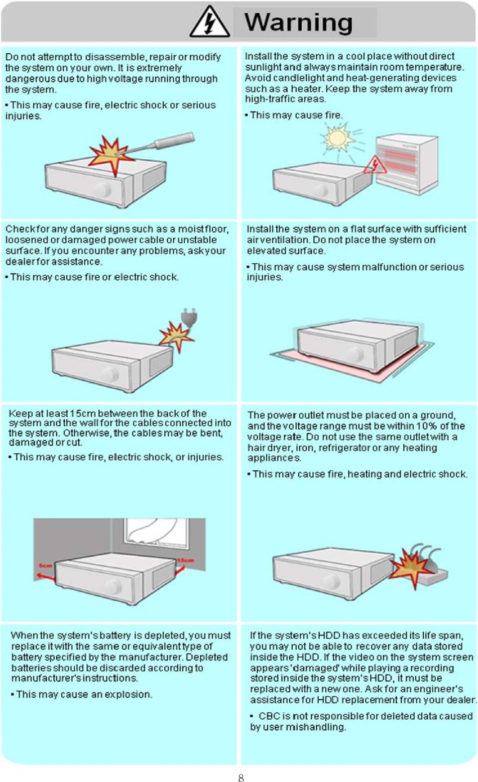
7 The following are warnings and precautions to ensure user safety and prevention of property damage. Please read the information below thoroughly. 7

8 8
9 9

10 10

11 Important Safety Instructions 1) Read all instructions contained in this manual. 2) Keep a copy of these instructions for future reference. 3) Read all warnings. 4) Follow all instructions. 5) Do not use this apparatus near water. 6) Clean only with a dry cloth. 7) Do not block any of the ventilation openings. Install in accordance with the manufacturer's instructions. 8) Do not install near any heat sources such as radiators, space heaters, stoves, or other devices that produce heat. 9) Do not defeat the safety purpose of the polarized or grounding type plug. - a polarized plug has two blades with one wider than the other. - a grounding type plug has two blades and a third grounding prong. - the wide blade and third prong are safety features provided for your safety. [NOTE: If the provided plug does not fit into the outlet, consult an electrician for replacement of the obsolete outlet.] 10) Protect the power cord from being walked on or pinched particularly at plugs, convenience receptacles, and the point where they exit from the apparatus. 11) Only use attachments or accessories that are specified by the manufacturer. 12) Use only with a cart, stand, tripod, bracket, or table specified by the manufacturer, or sold with the apparatus. When a cart is used, use caution when moving the cart/apparatus combination to avoid injury from tip-over. 13) Unplug this apparatus (if outlet is unprotected) during a lightning storm, or when unused for long periods of time. 14) Refer all servicing to qualified service personnel. Servicing is required when the apparatus has been damaged in any way, such as power supply cord or plug is damaged, liquid has been spilled or objects have fallen into the apparatus, the apparatus has been exposed to rain or moisture, does not operate normally, or has been dropped. 15) This equipment is intended for indoor use and all input/output wiring is limited to the inside of a building. 16) The power socket or outlet shall be installed near the equipment and should be easily accessible. 17) CAUTION: RISK OF EXPLOSION IF BATTERY IS REPLACED BY AN INCORRECT TYPE. ONLY DISPOSE OF USED BATTERIES ACCORDING TO THE INSTRUCTIONS. NOTE: Maximum Operating Temperature: 40 USB Power Output: 5V DC (Maximum 500mA) 11

12 Specifications & Organization 1. Device Specifications DR8HRD/DR16HRD Video Standard Audio Monitor Display Covert Camera Operation Event/Log Search Record Scheduling Remote Access Playback Pre/Post Alarm Buffers Video Activity Detection Multitasking Video Inputs Monitor Outputs Spot Output Audio Inputs Audio Output Resolution NTSC/PAL Bi-Directional Audio Real Time: 30ips (NTSC) or 25ips (PAL), per camera Programmable Up to 1,000,000 event log entries for user login/out, configuration changes, remote access, connects/disconnects. Daily or Weekly; adjustable by specific hour of the day, per channel Live View, Search, Playback, Configuration; via web browser or client software Up to 16-channel simultaneous playback Up to 5 seconds (Pre), 3 minutes (Post), programmable per camera HD: 1920X1080P VGA: 1280x1024 (60Hz) (monitors with Multi Sync function only) 22x15 grid; Sensitivity Levels: 10 (1 lowest, 10 highest) Triplex 8, 16 x 1Vp-p, CVBS, 75 ohms, BNC 1 x CVBS, VGA, HD Display 1 x 1Vp-p, CVBS, 75 ohms, BNC 4 x line-in, mono, line level, unbalanced, RCA jack 1 x line-out, mono, line level, unbalanced, RCA jack 352x240, 704x240, 704x480 (NTSC), 352x288, 704x288, 704x576 (PAL) Compression Standard H.264 Recording Speed DR16HRD: 480/400fps@D1, DR8HRD: 240/200fps@D1 Image Size 3-5 Kbyte (352x240, 352x288), 5-10 Kbyte (704x240, 704x288) 6-16 Kbyte (704x480, 704x576) Hard Disk Drive Capacity Secondary Storage 4 x HDD; no limit on HDD capacity USB default (USB memory stick, USB HDD) Alarm Inputs DR16HRD: 16+2, DR8HRD: 8+2 Alarm Outputs Archive/Snapshot File Formats Network Speed Control DR16HRD: 16 Digital + 4 Relay, DR8HRD: 8 Digital + 4 Relay AVI, JPG, BMP 8 levels (adjustable from 56Kbyte/s ~ 8192Kbyte/s) 12

13 Specifications & Organization 1. Device Specifications Pre-Alarm Recording OSD Languages Ethernet/LAN Network Interface Remote Function Digital Watermark Up to 5 seconds, programmable per camera English, Spanish, Portuguese, French, Russian, Polish, German, Italian Gigabit Ethernet, RJ-45 Live View, Search, Playback, Configuration, Archiving Support for CMS Software, Web R/A and Smart Phone Watermarked Video & Audio (for verification of data integrity & continuity) PTZ Control RS-485 Serial interface (full duplex) (two wires, +/-) Supply Voltage 12VDC, 5A, 100VAC-240VAC, 60/50Hz Operating Temperature Range 5 to 50 Housing Materials Dimensions (WxDxH) Weight Case Cover: Steel metal; Front Panel: Molded Plastic 43cm x 46cm x 9cm 7.3kgs 13
 PTZ Control RS-485 Serial interface (full duplex) (two wires, +/-) Supply Voltage 12VDC, 5A, 100VAC-240VAC,")
14 Specifications & Organization 2. Product Contents List Please check to make sure that all of the product contents are present after opening the product packaging. 1 Basic Contents 14

15 DR8HRD / 16HRD Unit 12V DC Adapter AC Power Cable Instruction Manual Remote Controller Installation CD AAA Battery x 2 2 Optional Contents Internal Hard Disk Drive 15

16 Specifications & Organization 3. System Organization VGA Monitor 16

17 Product Description 1. Front Panel 1 POWER : System Power On / Shutdown 2 DISPLAY : Switch Screen Division Modes (and Screen Rotation Mode) 3 SEQUENCE : Toggle Sequence Mode 4 PANIC : Trigger Panic Recording Mode and Panic Relay Output 5 ZOOM : Digital Zoom on Live View or Playback 6 LOCK : Toggle Front Panel Lock 7 ARCHIVE : Go to Archiving Menu 8 PTZ : Go to Camera PTZ Control Menu 9 SETUP : Go to Main Setup Menu 10 SEARCH : Go to Search Menu 11 USB PORT: USB Port(s) for either USB Mouse, USB Memory Stick, or USB HDD archiving devices. 12 RETURN : Cancel / Deselect / Return to Previous Screen 13 ENTER : Confirm / Select / Next Screen 14 LED Indicator : Indicates Present System Status. (POWER, REC, NETWORK) 15 Channel Selection Buttons (1 ~ 8 / 16) : Select Channel or Input Password Digits - Directional / Navigation Buttons (UP, DOWN, LEFT, RIGHT, ENTER) - Remote Controller Input Sensor (IR) - EJECT : Eject CD-ROM (Optional) - / : Focus Adjust (Near / Far) or Reverse Play / Fast Rewind - Ⅱ: Pause Playback - / : Iris Adjust (Open / Close) or Forward Play / Fast Forward - JOG / SHUTTLE : Outer wheel variable REW or FF; Inner wheel scroll frame-by frame while PAUSED. - HOLD : Hold Current JOG / SHUTTLE Position Tip If the Remote Control IR Sensor is blocked, the Remote Controller will NOT function properly. When a button is pressed on the Front Panel or on the Remote Controller, the DVR will beep, unless this feature is disabled from the main menu: System Setup Audio Buzzer. 17
 for either USB Mouse, USB Memory Stick, or USB HDD archiving devices.")
18 Product Description 2. Rear panel description. A. CAMERA INPUTS and LOOP OUTPUTS: Connect up to 16 camera inputs. Loop outputs can be used for connection to other equipment. B. COMPOSITE AND S-VIDEO MAIN: MONITOR CONNECTIONS Both outputs can be used at the same time if more than one main monitor connection is required. C. SPOT MONITOR OUTPUTS: Up to 4 spot monitors can be connected as necessary. D. ALARM INPUTS: Up to 16 alarm inputs can be connected and configured as high or low Inputs with common ground. E. ALARM OUTPUTS: Up to 16 alarm outputs can be connected and configured as high or low outputs with common ground.. F. RELAY OUTPUTS: Up to 4 Relay outputs can be connected and configured as high or low outputs with common ground. G. RS485: Can connect PTZ camera and controller by two RS485 connectors. Left side : for PTZ. Right side : for keyboard controller.. H. E-SATA: Can connect ESTG by E-SATA cable. I. AUDIO INPUTS & OUTPUTS: Up to 4 audio inputs and one audio output can be connected as necessary. J. VIDEO SIGNAL SWITCH: Can change Video input signal type. Can select Video output. 18

19 SYSTEM CONFIGURATION Selectable Video outputs are HD, VGA, SD. Video output selection to choose only one. If user selects the video output to two or more duplicate, the video may not be output normally. If monitor spec doesn t support DDC, the monitor can t be recognized. 1) If you select HD output, 2) If you select VGA output, 3) If you select SD output, K. USB PORT: Can connect USB mouse or USB device for backup. L. HD MONITOR OUPUT: Can connect HD monitor output. M. VGA: Can connect VGA monitor output. N. RS232: Serial port. O. LAN: Can connect to a router or internal network. P. POWER: Can connect Power cable. 19
 If you select HD output, 2) If you select VGA output, 3) If you select SD output, K. USB PORT: Can connect USB mouse or USB device for backup. L.")
20 SYSTEM CONFIGURE Remote Controller 3. Remote Controller description. POWER ON/OFF SETUP : Go to Main Setup Menu Channel Selection Buttons (also used for Password Digit Entry) ID Button Select DVR Unit ID ENTER : Confirm / Select / Next Screen RETURN Cancel / Deselect Previous Screen Navigation Buttons Used for Playback Control, Menu Navigation, and PTZ Control If there are multiple DVRs stacked or mounted in a rack, each DVR must be assigned a unique ID number, so that each DVR can be controlled with a single remote controller, referencing each DVR by its own ID. How to choose which ID to use on the remote controller: - Press the ID button. The system will display INPUT ID. - Enter the digits of the unit ID, and then press the ENTER button. (The default unit ID is 01 ). - To return back to normal control of the DVR, now press the RETURN button. - Factory Default Setting: Input unit ID 255 and then press ENTER and RETURN. 20

21 CONNECT & POWER ON Connect up to 16 CAMERA INPUTS as necessary. Connect one or more monitors to the DVR using the COMPOSITE, VGA, S-Video and HD MONITOR connections. Connect power to the DVR, using the provided AC power cord or DC 12V Power Adapter (depending on model). The DVR will check for proper power connection and emits two beeps if system power test is OK. Press the POWER BUTTON on the front panel of the DVR to begin operation. - The DVR startup screen detects and checks the status of hard drive and the CD-RW / DVD-RW drive. - After startup diagnostics are complete, the operator must login to the system. The default user name is ADMIN. - Using the CHANNEL SELECTION buttons, key in the digits of the default password ( 1234 ) and then press the ENTER button. - After DVR startup, the system will show the default display of all 16 channels in a standard 4x4 Screen Division mode. - The status bar at the bottom of the screen shows the current Date/Time and the percentage of Hard Drive capacity used. - The title for each channel is shown. - A red recording icon and the letter C in the top right of each channel display shows that the channel is recording in Continuous / Schedule mode. 21
22 LIVE DISPLAY MENU CONTROL All menus can be controlled from this Status Bar with either the USB mouse or Front Panel buttons. SCREEN DIVISION Select the DISPLAY button and the screen division menu will appear. Select the screen type (1, 4, 6, 8, 9, 16 and rotation sequence). SEQUENCE MODE (User can select a sequence as one of the options within the screen division menu.) Press the SEQ button. Each channel is shown full screen for an adjustable duration, before switching to the next channel. To stop the sequence on a particular channel, press the SEQ button again. More complex sequences can be programmed through the DISPLAY section of the setup menu.. 22
23 LIVE DISPLAY PTZ 1) CAM: Select the Channel of the PTZ device which you are controlling. 2) Preset: Select the number of the preset you are working with (1 ~ 254). 3) Set: Sets the current PTZ position as the selected Preset number. 4) GOTO: Tells the PTZ device to move to the position of the selected Preset. 5) Directional Arrows: moves the PTZ device in the direction specified. 6) Zoom / Focus / Iris: User can control each item with + or - button. 7) Parameter: Press this button and another window will appear. User can select an item from the PTZ parameter menu, and edit the settings in order to fine-tune the speed of pan-tilt-zoom motions, or to enable advanced features, such as Auto Focus and Auto Iris (only on supported PTZ devices). DIGITAL ZOOM Right-Click within Live View mode, and choose ZOOM. Or select the ZOOM function from the status bar. While viewing a channel in full screen, the user can digitally zoom into a particular area of that channel by up to 14X. The small PIP window at the bottom-right shows the full image and the main display area shows the zoomed portion. To use the digital zoom, select the required channel and press the ZOOM button. 23
24 LIVE DISPLAY LOG SEARCH User can see a live event log window, which shows each new event as it occurs. Caution) When POS function is activated, user can t use Live LOG function. PANIC RECORDING - This function button is used to toggle the Panic Recording mode On/Off. - When Panic Recording mode is enabled, you will see a red recording icon with P for Panic. - When Panic Recording mode is enabled, the system will record all channels, as per the Panic Recording settings. - All resolution and image rate settings related to Panic Recording are configured within the Record menu. 24
25 LIVE DISPLAY QUICK MENU You may access the Quick Menu by right-clicking on any channel which you would like to control. 1. Freeze On/Off: User can freeze the live display of any channel. While the other channels will continue to show live view video, the frozen channel display is stopped. Click once more to return to live view video. 2. PTZ Please refer to PTZ menu of Page Zoom Please refer to ZOOM menu of Page PANIC REC Start (Stop) Please refer to Panic Record menu of Page
26 SYSTEM SETUP Click the MENU button and choose the SYSTEM SETUP menu. - To navigate around any items in the setup menu, use the CURSOR KEYS and the ENTER and RETURN buttons. - In general, the ENTER button is used to select a particular field to edit, and then is pressed again to confirm changes. - The RETURN button is used to cancel or deselect, or to step back one screen while navigating the menu system. - To configure all system settings, highlight SYSTEM SETUP and press ENTER. 26
27 SYSTEM SETUP CAMERA From the System Setup menu, click on the CAMERA submenu. CAMERA: CAMERA SETUP Left-click on the CAMERA SETUP menu. Double-click on the TITLE field to change the camera name. Click the COVERT or AUDIO fields for the desired channel. Then, use the button to modify each value. TITLE: For each camera, a title of up to 11 characters can be set, using the virtual keyboard. COVERT: When it is set to ON, the camera image is not displayed in live display but continues to be recorded. AUDIO: Determines the audio recording channel which will be paired with each video channel. CAMERA : COLOR SETUP While modifying any value within the color setup, the selected channel will be displayed full screen. BRIGHTNESS, CONTRAST, TINT and COLOR can be modified as necessary. To modify a different channel, highlight the CAMERA field, and choose the desired channel. Press RETURN when all changes are completed. NOTE: These settings will not change the properties of the recorded image, only what is being displayed on screen. 27
28 SYSTEM SETUP Modify each value using the button. The selected channel is displayed in full screen mode. BRIGHTNESS, CONTRAST, TINT and COLOR can be changed as necessary. To modify a different channel, highlight the CAMERA field, and choose the desired channel. Press RETURN when all changes are completed. CAMERA : PTZ SETUP Click the PTZ SETUP menu. Click on any field to modify its value. Change the value by the button. ADDRESS: The unique ID of the PTZ device. PROTOCOL: The protocol of the PTZ device. BAUD RATE: The baud rate of the PTZ device. DETAIL: Detail setting for PTZ device. (Refer to the next page.) TOUR: It is the PTZ TOUR function that it realized to S/W at DVR. It is independent of Tour supporting of PTZ Protocol. It is a monitoring function that PTZ Preset function is used with setting preset order and dwell time. 28
29 SYSTEM SETUP Advanced PTZ properties can be adjusted for each channel using the DETAIL button. Some settings, such as Auto Focus, may not be compatible with all PTZ devices. If this is the case, changing this value will have no effect on PTZ control. Click the TOUR button and set the MODE to [AUTO] to use TOUR function. First of all, please set PRESET number on the live PTZ mode. Then set the PRESET number 1 to 16 and DWELL Time. DWELL TIME means staying time on position until move next preset position. 29
30 SYSTEM SETUP CAMERA : MOTION SENSOR Click on the MOTION SENSOR menu. Click on a SENSITIVITY value for the desired channel. Then use the button to increase or decrease the sensitivity. SENSITIVITY: Determines the degree of motion required before recording is activated. (1: Least Sensitive to Motion - 10: Most Sensitive to Motion) Click the button to edit the motion detection area. AREA SETUP: Choose this option to define which areas of the image are sensitive to motion. Click on individual squares to select or deselect each square. Click-and-drag to select or deselect entire areas of the grid. To quickly select or deselect the entire grid at once, right-click and choose either SELECT ALL or DESELECT ALL. - Red outlined grid area: Selected area. - White outlined grid area: Unselected area. - Green outlined grid square: Current position of mouse cursor. 30
31 SYSTEM SETUP DISPLAY From the System Setup menu, click on the DISPLAY submenu. DISPLAY - OSD Click on the OSD submenu and then click on any field. Then, click on the button to modify the value. STATUS BAR TIMEOUT: Toggles the status bar at the bottom of screen in Live View mode ON / OFF. CAMERA TITLE: Determines whether the camera title is displayed for each channel. RECORDING MODE ICON: Toggles the DVR recording status icons shown at the top right of each channel window. BORDER: Determines whether there is a border grid shown around each channel in each Screen Division mode. BORDER COLOR: If the border grid is set to ON, the user can choose the color of the grid. MOTION SENSOR DISPLAY: This feature can be used to determine which areas within a channel are detecting motion in real-time. The motion sensor display can be used to troubleshoot false motion activations. OFF normal display mode. ON areas where motion is detected are highlighted with colored blocks. MOTION COLOR: The color of the blocks displayed when MOTION SENSOR DISPLAY is set to ON. LANGUAGE: Determines the DVR Operating System language. To change any of these settings, highlight OSD and press ENTER to select. Use the CURSOR KEYS to navigate to the desired option. Press ENTER to select the option, and use the CURSOR KEYS to change the setting. Press ENTER to confirm the setting or RETURN to cancel. 31
32 SYSTEM SETUP DISPLAY - MONITOR Click the MONITOR menu, then click on any field. Use the button to modify the value. SEQUENCE DWELL: The amount of time that each screen is displayed in a sequence. SPOT-OUT DWELL: The amount of time that each screen is displayed on each of the spot monitor outputs. DE-INTERLACE MODE: When recording any channels in D1 resolution (704 x 480), this may be set to ON, to prevent interlaced motion distortion during playback. ALARM POP-UP MODE: When enabled, an alarm input will cause the associated channel to display full screen. ALARM POP-UP DWELL: Determines the amount of time a full screen popup is displayed after an alarm input. If the alarm condition continues, the pop-up screen will be displayed constantly. MOTION POP-UP MODE: When enabled, motion detection will cause the associated channel to display full screen. MOTION POP-UP DWELL: Determines how long the full screen popup is displayed after motion detection. If motion continues, the popup screen is displayed constantly. To change any of these settings, highlight MONITOR and press ENTER to select. Use the CURSOR KEYS to navigate to the option required. Press ENTER to select the option (the cursor changes to orange) and use the CURSOR KEYS to change the setting. Press ENTER to save the setting, or press RETURN to cancel. 32
33 SYSTEM SETUP DISPLAY - SEQUENCE Click the SEQUENCE menu. - When the SEQ button is pressed, the default sequence will cycle through all 16 channels, one by one, in full screen. - Sequence setup allows the user to define a custom sequence pattern, using either full screen or mixed multi-screen views, which can be comprised of any number of channels in any order. Click the ADD button to add a new sequence. - To add a new sequence, highlight ADD and press ENTER. - Sequence Title is highlighted. Press ENTER to bring up the virtual keyboard, and key in a name for the new sequence. Click on the ACTIVATION field, and click the button to turn the sequence activation ON. Select SAVE. Then, the menu pictured will appear. 33
34 SYSTEM SETUP Click ADD. The Sequence Setup submenu appears. - Determine the Screen Division mode under the VIEW TYPE section. - Assign the desired channel under the CONFIGURE section. - When all sequence settings have been entered correctly, click CONFIRM. - To add an additional mode, click ADD continuously. After finishing the setup, click CLOSE. - To modify the current pattern, double click it. The Sequence Setup window will appear again. - The new sequence has now been saved, and can be started by pressing the SEQ button while in Live View mode. 34
35 SYSTEM SETUP DISPLAY SPOT OUT. Click on the SPOT-OUT menu and click the camera channel for ON/OFF. The DVR has 4 SPOT MONITOR OUTPUT (Digital Spot) and user can assign the SPOT OUT display for each channel Spot monitor displays a full screen sequence of particular channels, depending on the settings within this menu. For spot monitor, the operator can decide which channels are to be displayed in the sequence. By default, Spot Monitor output is set to run a sequence of all 16 channels. SPOT TITLE: Input the title of each spot monitor. ACTIVATION: Toggle each spot monitor ON/OFF. - Click MODIFY. (Below is default setup) - To modify the current display, double-click the display. Then Spot Sequence Setup window will appear. Setup method is similar to the Sequence setup performed earlier (can only use single or quad mode for spot output). - To add an additional display, click ADD. 35
36 SYSTEM SETUP SOUND From the System Setup menu, click on the SOUND menu. SOUND - AUDIO Click on the AUDIO menu, and click on any field. Use the button to modify each value. LIVE AUDIO: When enabled, the selected audio channel can be monitored from the AUDIO OUTPUT. DEFAULT AUDIO CHANNEL: Specify which one of the 4 AUDIO INPUTS is routed to the AUDIO OUTPUT. NETWORK AUDIO TX: When enabled, live and playback audio is transmitted to a remote PC connection. NETWORK AUDIO RX: When enabled, allows a remote PC connection to send audio back to the DVR. SOUND - BUZZER Click on the BUZZER menu, and click on any field. Use the button to modify each value. KEYPAD: When enabled, each front panel button keypress is confirmed by a system beep. 36
37 SYSTEM SETUP SYSTEM From the System Setup menu, click the SYSTEM menu. SYSTEM - DATE / TIME Click the DATE / TIME menu, and click on any field. Use the button to modify any value. DATE TIME: Allows the operator to set or modify the current system date & time. DATE FORMAT: Determines the format in which the date is displayed. (MM / DD / YYYY) TIME FORMAT: Determines how the time is displayed. (AM/PM or 24-hour) NETWORK TIME SERVER SETUP: If the DVR is connected to the Internet, the time and date can be accurately set by selecting SYNC and pressing ENTER. TIME ZONE SETUP: should be set according to the region that the DVR is used in. D.S.T.: When enabled, the DVR will automatically adjust for daylight savings time changes in the spring and autumn. 37
38 SYSTEM SETUP SYSTEM-SYSTEM MANAGEMENT Click on the SYSTEM MANAGEMENT menu. SYSTEM INFORMATION: User can see the system information as below. S/W version: Shows the firmware version of the DVR. H/W version: Shows the hardware version of the DVR. VIDEO SIGNAL TYPE: The DVR automatically switches between PAL and NTSC depending on the video format of the Channel 1 input signal at the time of power on. DISK CAPACITY: The first value shows the amount of hard drive capacity used by recorded footage. The second value shows the total hard drive capacity installed. IP ADDRESS: Shows either the manual IP address entered in the NETWORK menu, or the automatic IP address assigned by a DHCP server, if enabled. MAC ADDRESS: Shows the MAC (Media Access Control) address of the DVR. It is a unique identifier no other network device has the same MAC address. DDNS DOMAIN NAME: If DDNS is enabled, the host DDNS server is specified here. RTSP SERVICE PORT: The port number that the DVR uses to support remote connection from the client software. WEB SERVER PORT: The port number that the DVR uses to support remote connection from Internet Explorer or other web browsers. SYSTEM NAME: This field is used so that notification s can be identified by system name. 38
39 SYSTEM SETUP F/W UPDATE: Firmware updates may be released periodically to enhance system performance and add extra features. The user can upgrade the DVR firmware locally, using a USB memory stick. Select the Device where the Firmware Update files are located. After selecting the F/W version from F/W list, press UPGRADE. This will start the Firmware Update process. FACTORY DEFAULT: If settings have been changed which cause erratic behavior, the factory default configuration can be reloaded. SYSTEM DATA: The system configuration can be saved to a USB memory stick. At any time, it can be reloaded in case of accidental factory reset, or can be transferred to another DVR if multiple units need to be installed with the same settings. All information is saved apart from network settings and system name. PASSWORD: Determines whether the system must be used every time when entering the menu system. PASSWORD EXPIRED: Determines the amount of time before the system password expires. SYSTEM - CONTROL DEVICE Click on the CONTROL DEVICE menu. This will allow up to 254 DVRs to be controlled from the same keyboard controller. SYSTEM ID: If more than one DVR is connected on the same RS-485 bus, each one must have a unique ID. Note: If more than one DVR is being used, each DVR must have a unique ID to use the Handheld IR Remote Controller. PROTOCOL: Must be set to match the Protocol of the Control Device. BAUD RATE: Must be set to match the Baud Rate of the Control Device. 39
40 SYSTEM SETUP SYSTEM: POS SETUP POS ENABLE: This determine POS enable / disable. BAUDRATE: Must be set to match the baud rate of the POS device. PROTOCOL: Must be set by POS device.. ADDRESS: This determine POS device address of each channel. Caution) When POS function is activated, user can t use Live LOG function and Control device.. 40
41 SYSTEM SETUP USER From the System Setup menu, click on the USER menu. USER - USER MANAGEMENT By default, the DVR is configured with a user ID of ADMIN, belonging to the ADMIN group, with a password of Within this menu, you have the ability to add new users, or modify the details for existing users. To modify user details, click or highlight the user with the green cursor square, and press ENTER. The maximum number of users that can be created is 8. To edit a user account, double-click on the user name. After changing, click OK to confirm changes. USER ID: Edit the User ID using the virtual keyboard. (Maximum of 10 characters) PASSWORD: Change the password using the virtual keyboard. (Maximum of 4 characters) GROUP: Users can be assigned to one of three groups - ADMIN, MANAGER or USER (see User Authority setup). Enter the user s address if notification is required. (maximum of 64 characters) NOTIFICATION: Enable or disable notification for the specified user. NOTE: For security reasons, it is recommended that the ADMIN user password be changed after installing the DVR. 41
42 SYSTEM SETUP For ADD, double click on the each tap after clicking ADD. After changing, click OK. USER ID: Edit the user ID using the virtual keyboard. PASSWORD: Change the password using the virtual keyboard. GROUP: Users can be assigned to one of three groups - ADMIN, MANAGER or USER. Enter the user s address if notification is required. NOTIFICATION: Enable or disable notifications for the specified user. USER - USER AUTHORITY User can configure the specific authority and permissions for the MANAGER and USER groups. To confirm changes, click the APPLY button after selecting each of the desired items. NOTE: Any user can be deleted except the default ADMIN user account. USER - LOG OUT utomatically logged-out of the menu. DURATION: Determines the amount of time before a logged-in user is automatically logged-out of the menu. 42
43 SYSTEM SETUP NETWORK From the System Setup menu, click on the NETWORK menu. NETWORK- IP SETUP Click on the IP SETUP menu. DHCP: When enabled, the DVR will obtain an IP address automatically from a router or DHCP server, upon reboot. WEB SERVICE: When enabled, allows remote connections using Internet Explorer or other compatible web browsers. IP ADDRESS: If DHCP is not being used, the IP address can be manually set by the user. GATEWAY: If DHCP is not being used, the gateway IP address can be manually set by the user. SUBNET MASK: If DHCP is not being used, the subnet mask can be manually set by the user. 1ST DNS SERVER: If DHCP is not being used, the first DNS server can be manually set by the user. 2ND DNS SERVER: If DHCP is not being used, the second DNS server can be manually set by the user. RTSP SERVICE PORT: If the connected Router supports UPnP (Universal Plug and Play) functionality, when you click AUTO PORT, the port forwarding is automatically configured and also can delete the port & test the port whether working or not. WEB SERVER PORT: If connected Router support UPNP (Universal plug and play) function, when you click the AUTO PORT, the port forwarding is automatically setup. And also can delete the port. The port number that the DVR uses to support remote connection from Internet Explorer or other compatible web browsers. ALIAS: When you enter the DDNS HOST NAME within DDNS setup (see next page), you can see the DDNS Information, for example: MAX TX SPEED: Specifies the maximum bandwidth that the DVR can use during a remote connection. 43
44 SYSTEM SETUP NETWORK-DDNS DDNS: When enabled, the DVR can be accessed through a Dynamic DNS server. (This is commonly used if a particular broadband connection does not have a Static IP address.) CAUTION: To use the DDNS function, the user must configure port forwarding. a. Default WEB SERVICE PORT : 8080 b. Default RTSP SERVICE PORT : 554 The Default DDNS Host Name is the Mac Address of the DVR, so the user can connect through two different ways: (Mac Address or Custom DDNS Host Name) a ff00213.dvrlink.net b dvrlink.neet (user can choose any DDNS Host Name) NETWORK - Click on the submenu. SERVER: The SMTP outgoing server that will be used to send notifications. PORT: The outbound service port number. SECURITY: Turn OFF if the SERVER does not require a username and password for SMTP authorization. USER: Enter the user name for the account which will be sending messages from the SMTP server. PASSWORD: If SECURITY is set to ON, enter the password here. FROM: Input the address or any text. It is only used for test ( sender) TEST Test the configuration of the outgoing SMTP mail server. 44
45 SYSTEM SETUP EVENT / SENSOR From the System Setup menu, click on the EVENT / SENSOR menu. EVENT / SENSOR - HDD EVENT Click on the HDD EVENT menu, and choose any field.. Use the button to modify the value. The DVR will continually monitor the health of the hard drives in the system and detect problems that may be developing. SMART ALARM: Enables S.M.A.R.T. (Self-Monitoring, Analysis, and Reporting Technology) hard disk monitoring. CHECK INTERVAL: Frequency of testing. DISK FULL EVENT: Determines whether a Disk Full condition would result in a HDD event. EVENT / SENSOR - ALARM INPUT Click on the ALARM INPUT menu, and choose any field. Use the button to modify the value. The menu will determine the behavior of each of the 4 alarm inputs. OPERATION: Alarm inputs can be enabled or disabled. TYPE: Alarm inputs can be set as normally open (N/O) or normally closed (N/C). 45
46 SYSTEM SETUP EVENT / SENSOR - ALARM OUT Click on the ALARM OUTPUT menu, and click on a field. Use the button to modify the value. This menu will determine the behavior and actions that will trigger each of the 1 alarm output. Behavior settings ALARM OUT: Choose which alarm output to configure. OPERATION: The selected alarm output can be enabled or disabled. MODE: Can be either set as TRANSPARENT (the output is active only when the trigger criteria is present) or LATCHED (the output is active for a set period of time after the trigger). DURATION: In LATCHED mode, the amount of time that the alarm output remains active after it has been triggered. TYPE: Can be set to high (0V to +5V when activated) or low (+5V to 0V when activated). HDD EVENT: Determines whether a hard drive event will trigger an alarm output. Action settings ALARM: Determines whether the specific channel alarm input would trigger the alarm output. VIDEO LOSS: Determines whether video loss on any of the selected channels will trigger the alarm output. MOTION: Determines whether motion detection on any of the selected channels will trigger the alarm output. NOTE: Remember to select APPLY and press ENTER to save all settings before exiting these menus. 46
47 SYSTEM SETUP EVENT / SENSOR - BUZZER OUT Click on the BUZZER OUTPUT menu, and click on a field. Use the button to modify the value. This menu will determine the behavior and actions that will trigger the internal buzzer. Behavior settings OPERATION: The internal buzzer can be enabled or disabled. HDD EVENT: Determines whether a hard drive event will activate the internal buzzer. MODE: Can be set as either TRANSPARENT (the buzzer sounds only when the trigger criteria is present) or LATCHED (the buzzer sounds for a set period of time after the trigger). DURATION: In LATCHED mode, the time that the buzzer will continue to sound after it has been triggered. Action settings ALARM: Determines whether alarm inputs will activate the internal buzzer. VIDEO LOSS: Determines whether video loss on any of the selected channels will sound the internal buzzer. MOTION: Determines whether motion detection on any of the selected channels will sound the internal buzzer. NOTE: Remember to select APPLY and press ENTER to save all settings before exiting these menus. 47
48 SYSTEM SETUP EVENT / SENSOR - NOTIFICATION Click on the NOTIFICATION menu, and click on a field. Use the button to modify the value. This menu will determine the behavior and actions that will send an notification to a remote user. Behavior settings NOTIFICATION: notification can be enabled or disabled. SETUP CHANGE: Determines whether a change to the system configuration would cause an to be sent. HDD EVENT: Determine whether a hard drive event would cause an to be sent. BOOTING EVENT: Determines whether a booting event would cause an to be sent. Action settings ALARM: Determine whether alarm inputs will cause an to be sent. VIDEO LOSS: Determine whether video loss on any of the selected channels will cause an to be sent. MOTION: Determine whether motion detection on any of the selected channels will cause an to be sent. FREQUENCY: Minimum period of time between sending notifications (max. 60 minutes). NOTE: Notification settings must also be configured within the MAIL and USER MANAGEMENT menus. 48
49 SYSTEM SETUP DISK MANAGEMENT Click on the DISK MANAGEMENT menu. To manage the internal hard drives, from the System Setup menu, highlight DISK MANAGE and press ENTER. RECORD TIME LIMIT: In certain circumstances, it may be necessary to limit the amount of footage stored. on the DVR (to comply with data protection laws, for example). Recording can be limited to the following time periods: 12 hours, 1, 2, 3, 4, 5, 6 days, 1, 2, 3 weeks or 1, 2 months. Once the DVR has reached the recording time limit, the system will start to overwrite the earliest recorded footage. OVERWRITE: When enabled, the DVR will start overwriting the earliest recorded footage once the hard drive is full. In this case, the percentage of hard drive used shown in live display will always be 99%. When disabled, the DVR will stop recording when the disk becomes full. FORMAT: If necessary, all recorded footage can be erased from the DVR using this option. NOTE: When the RECORD TIME LIMIT is set, the percentage of HDD used shown in live display mode may never reach 99%. For example, if the total HDD capacity of the DVR allows for a recording time of 4 days under normal operation, if the RECORD TIME LIMIT is set to only 2 days, the percentage of HDD used would never exceed 50%. NOTE: When a RECORD TIME LIMIT is set, the OVERWRITE option cannot be changed. 49
50 RECORD SETUP From the Main Menu, click on the RECORD menu. To configure the recording behavior of the DVR, highlight RECORD MENU and press ENTER. RECORDING OPERATIONS Click on the RECORDING OPERATIONS menu. Click on any field, and use the button to modify the value. SCHEDULE MODE: Either DAILY (one schedule will apply to every day of the week) or WEEKLY (each day of the week has its own schedule). PRE-EVENT RECORDING TIME: When the DVR is not in continuous recording mode, this setting determines the amount of footage that is always recorded before an event occurs. (motion detection, alarm input, etc.) POST-EVENT RECORDING TIME: When the DVR is not in continuous recording mode, this setting determines the amount of footage that is always recorded after an event occurs. (motion detection, alarm input, etc.) PANIC RECORDING: User can select the panic recording working option. DISABLE: even though pressing the panic button or detecting the sensor, it don t work. AUTO: It is related with RANIC RECORDING TIME SETUP. MANUAL: It works by pressing the panic button or detecting the sensor. PANIC RECORDING TIME: After passing the selected time, it stops the panic recording. (5, 10, 20, 30, 40, 50,60MIN) 50
51 RECORD SETUP CONTINUOUS / MOTION RECORDING SETUP Click on the CONTINUOUS / MOTION RECORDING menu. This menu allows the operator to configure continuous and motion-activated recording, based on a schedule. There are 2 sections to this menu: SIZE / FPS / QUALITY: Recording settings for each channel can be defined across a 24-hour period, in blocks (for example between 09:00 and 18:00) or by each individual hour. Note that when SCHEDULE MODE is set to WEEKLY, each day of the week can be individually configured. ACTIVATION: This section determines at what times the DVR will record and whether it is set to continuous or motion. SIZE / FPS / QUALITY Click on the SIZE / FPS / QUALITY tab. To change SIZE / FPS / QUALITY settings, highlight CONTINUOUS / MOTION SETUP and press ENTER. Ensure that SIZE / FPS / QUALITY is highlighted in yellow, and press ENTER again. The 24 hour time bar is highlighted in green. 51
52 RECORD SETUP SIZE / FPS / QUALITY (continued) Click on the TIMELINE to select a block of time. Press ENTER to display the green cursor. The green cursor square shown represents one hour. (In this case between 00:00 and 01:00). The table below the time bar shows the recording settings for this time period. Click and drag on the TIMELINE to select a block of time. Example: To change the recording settings between 09:00 and 18:00. Use the CURSOR KEYS to move the green cursor to the 09:00 position and press ENTER. The cursor changes to orange to show the start position. Use the CURSOR KEYS to stretch the orange cursor across to the 18:00 position. 52
53 RECORD SETUP SIZE / FPS / QUALITY (continued) Click on the SIZE, FPS, QUALITY or AUDIO fields. Use the button to modify the value. Press ENTER. Recording settings for the selected time period are displayed. Maximum recording frame rate is 480FPS at resolution of D1. SIZE: Recording resolutions of CIF (352x240), 2CIF (704x240) or D1 (704x480) can be selected for each channel. FPS: Image rates between 1 and 30ips can be set for each channel. QUALITY: Five different recording quality levels can be set for each channel. AUDIO: If audio devices are connected to the DVR, any audio channel can be assigned to any of the video channels. During playback, when a channel is viewed in full screen, the assigned audio channel will play back at the same time. Adjust the values as desired and select OK to finish and return to the parameter menu. Other time periods can be configured in the same manner. NOTE: Remember that if the SCHEDULE MODE is set to WEEKLY, recording settings need to be changed for each day as well as for each particular time. NOTE: The DVR supports a maximum recording rate across all channels of 480frames per second at D1 resolution. As settings are adjusted, the frames available at bottom left displays the number of available images still remaining and must always be zero or higher. If, while changing recording settings, this figure becomes negative, recording resolutions and/or image rates must be lowered to increase the frames available value to zero or above. 53
54 RECORD SETUP SCHEDULE Click on the ACTIVATION menu. To change ACTIVATION settings, highlight CONTINUOUS / MOTION RECORDING and press ENTER. Use the CURSOR KEYS to highlight ACTIVATION and press ENTER. The schedule box is highlighted in green. Press ENTER to display the green cursor square. Example: To set all channels to motion detection recording only between 18:00 and 00:00. Use the CURSOR KEYS to move the green cursor to the 18:00 position and press ENTER. The cursor changes to orange to show the start position. The schedule grid uses differently-colored blocks to denote the different recording modes: - NO COLOR blocks: No recording. - LIGHT BLUE blocks: The DVR will record continuously. - DARK BLUE blocks: The DVR will only record while motion is detected. - PINK blocks: The DVR will record continuously and with motion event. 54
55 RECORD SETUP ALARM RECORDING SETUP Click on the ALARM RECORDING submenu. The layout of this menu is very similar to the CONTINUOUS / MOTION RECORDING menu. This menu screen allows the user to configure alarm-activated recording. There are 2 sections to this menu: SIZE / FPS / QUALITY: Recording settings for each channel can be defined across a 24-hour period, in blocks (for example between 09:00 and 18:00) or for each individual hour. ACTIVATION: This section determines at what times the DVR will record and whether it is set to continuous or motion. NOTE: Please refer to the instructions for the CONTINUOUS / MOTION RECORDING menu for details on setting up the SIZE / FPS / QUALITY and ACTIVATION tabs within the ALARM RECORDING menu. Alarm-activated recording can be used in conjunction with the CONTINUOUS / MOTION RECORDING menu. The DVR can be configured to record continuously at a low image rate ( CONTINUOUS / MOTION RECORDING menu), and then increase to a higher image rate during an alarm condition. ( ALARM RECORDING menu) PANIC RECORDING SETUP Click on the PANIC SETUP submenu. Click on the SIZE, FPS, QUALITY and AUDIO. During a Panic Recording condition, the DVR will override all other recording settings and record continuously on all channels as per the settings configured here. 55
56 RECORD SETUP RECORD: NETWORK STREAMING SETUP Click the NETWORK STREAMING menu. Select the Size, FPS, Quality and audio. During Network Streaming mode, the DVR is possible to set remotely uploaded video, audio stream with using client program like Web RA. Maximum recording frame rate is 120FPS at resolution of 1CIF (352x240). 56
57 SEARCH SEARCH To search for a particular section of recorded footage, click or press the SEARCH button. To protect unauthorized viewing of footage, only ADMIN and MANAGER user groups can playback footage (by default). To login as ADMIN, enter the default password of 1234 and press ENTER. SEARCH SEARCH BY TIME Click on the desired search date from the calendar. The DVR uses a calendar and timeline search method for quick access to recorded footage. The calendar displayed on the left side of the screen shows the current month. Days which have any recorded footage will be highlighted in green. The timeline on the right side of the screen shows a 24-hour status of all channels for the selected day. Each block represents 15 minutes of time. Light blue areas indicate the presence of recorded video. Panic: White Motion: Green Timer: Sky blue Alarm: Red 57
58 SEARCH Click and drag the time bar across the timeline. Press ENTER to select the calendar and use the CURSOR KEYS to move the purple square to the desired day. As different days are selected, the timeline display also changes to show the timeline of recorded footage for that day. Press ENTER to choose the date and move to the timeline. Click the PLAY button on the bottom of the screen. Use the CURSOR KEYS to move the timeline cursor left or right to select the desired time segment. Each movement of the timeline cursor increases or decreases the time by 15 minutes. The currently selected time is displayed above the calendar. Press PLAY to begin playback from the selected time. 58
59 SEARCH SEARCH MODE: MULTI PLAYBACK PLAY (Multi view): The default playback mode is 16 screen display. By pressing DISPLAY or using the CHANNEL SELECTION buttons, it is possible to display single screen or other multi screen formats in a similar way to the live display mode. When playback is paused, the <<, >> can be used to accurately move the footage forward or backwards, frame by frame. Playback speed and direction can also be controlled using the five playback buttons. 59
60 SEARCH During playback, user can put a bookmark on the recorded data that needs to be archived later. Click the button at the time the archive is to be started. Then playback will halt and menu below will appear. After inputting the TAG name, press START. Then the system will return to playback mode. Click the button again at the end point of the archive. The menu below will appear once again. RESERVE: Press this button to reserve the currently selected data. CONTINUE: Press this button to go back and reserve more data. The system will return to playback mode. START: Press this button to start the reservation. STOP: Make sure to press this button to reserve the current data first. Then user can select RESERVE. CLOSE: Close the reservation menu and finish archiving. NOTE: Reserved data will be kept on the HDD. The user can view all of the reserved clips listed in RESERVED DATA MANAGEMENT within the ARCHIVING menu. 60
61 SEARCH To exit playback mode and return to the search screen in order to choose another time and date, press RETURN. To exit the search screen and return to Live View mode, repeatedly press the RETURN button. SEARCH SEARCH BY EVENT The DVR event log stores events such as motion and alarm activated recording, video loss etc. To search for an event and playback the recorded footage, press the SEARCH button and log in as ADMIN with the default password of Click the SEARCH BY EVENT menu and select each desired channel and condition.. Check all desired options. Use the buttons to select the desired date and time range to search for events. 61
62 SEARCH Click the SEARCH button to search for events.. Highlight SEARCH and press ENTER to display the event log for the criteria selected. To playback footage for a particular event, select the event from the list using the CURSOR KEYS and press ENTER. Playback resumes from the moment the selected event occurred and continues until stopped by the user. During event-based playback, the SHUTTLE WHEEL, JOG RING and playback buttons can be used as normal. To stop playback and return to live view mode, repeatedly press the RETURN button. The event log search contains the following selectable entries: ALARM: When this option is checked, all alarm input events are displayed for the chosen date range. TIMER: When this option is checked, scheduled recording operations are displayed for the chosen date range. MOTION: When this option is checked, all motion detection events are displayed for the chosen date range. ETC: When this option is checked, all other events (video loss, remote logins, etc.) are displayed for date range. 62
63 SEARCH SEARCH : POS EVENT SEARCH The DVR POS event log stores events such as price, quantity, item keyword, date, etc. On SEARCH BY POS EVENT menu, it can search log price, quantity, item keyword, date, etc, and playback recorded video. Click the SEARCH BY POS EVENT menu and select each desired channel, condition and item keyword. Then click the time with button to change. Click the SEARCH button. 63
64 To playback footage for a particular event, select the event from the list using the CURSOR KEYS and press ENTER. Playback resumes from the moment when the selected event occurred and continues until stopped by the operator. During event search playback, the playback buttons can be used as normal. To stop playback and return to live view mode, repeatedly press RETURN. 64
65 ARCHIVING NEW ARCHIVING To archive recorded footage to a USB Memory Stick or CD/DVD, press the ARCHIVE button. To protect unauthorized viewing and distribution of footage, only the ADMIN user level can archive footage (by default). To login as ADMIN, enter the default password of 1234 and press ENTER. CREATE A NEW ARCHIVE Click on a field to configure each of the archive settings. Use the button to modify each value. Click QUERY to view the data size of the selected clip. It is useful to use QUERY first before selecting BURN or RESERVE. Press the RELEASE button to reset the results from any previous QUERY. RESERVE: Press this after inputting the TAG name to reserve the selected clip. OR BURN: Press this after inputting the TAG name. Then press START after viewing the confirmation window. If press to STOP during burning, it will be stopped. NOTE: To use a USB Memory Stick, it must be inserted into the DVR before entering the archiving menu. 65
66 ARCHIVING RESERVED DATA MANAGEMENT AVI ARCHIVING LIST: User can see the list of data that has been reserved from the Create New Archive menu INFORMATION: The detailed information of each clip that has been reserved. DELETE: Delete the selected clip from the list of reserved data. BURN: Perform an archiving operation using the selected clip. Once all the desired archive options have been selected, highlight the START button and press ENTER. The DVR displays a list showing the exact information to be archived and the total archive size. If the ORIGINAL SIZE of the archive is larger than the amount of available space on the backup media, the END TIME of the archive is adjusted accordingly. The MODIFIED SIZE is the final file size of the archive. Select OK and press ENTER to begin the archiving process. Once extracted, the footage is copied to USB. Depending on the amount of footage selected for archive, the extracting and burning process may take some time, during which the operating system of the DVR cannot be used. Normal recording is unaffected by the archive process. NOTE: In case the selected data size for archiving exceeds the size of the USB media being used, the user may choose to continue the archive on additional pieces of media until complete. Insert a new drive after the first archive has completed, and click or press CONTINUE. 66
67 FTP SETUP FTP Archiving is possible if setting up the HOST Name, Port number, User Name, and Password having become setting to FTP server. FTP Archiving is possible on New Archiving or Reserved Data Management.. Archiving data is appeared in Directory of the name that they set up to 'DIRECTORY' if got from FTP backup. FTP TEST normally uses it to purposes to test Archiving possible to the FTP server which a user set up. 67
68 WEB CONNECTION SETUP PRELIMINARY BEFORE CONNECTING When configuring for a web or remote connection to the DVR, Ports 554 and 8080 should be forwarded within the router. Refer to the user s manual of your specific model of router for information on port forwarding configuration. WEB / REMOTE CLIENT - MINIMUM PC REQUIREMENTS CPU RAM Video Card Video RAM Monitor Operating System Web Browser Network / LAN DirectX P4 (3.0GHz or higher) 512MB (or higher) GeForce MS 400, ATI Radeon 7500 (or higher) GeForce 8 Series (or higher) 64MB (or higher) 1280x1024 Windows XP Service Pack 2 (or higher) IE 6.0 (or higher) at least 100Mbps Version 7.0 (or higher) HOW TO CONNECT Input the IP address or URL of the DVR into the Address Bar of your web browser. If using a DDNS service, you may input the URL as shown below: (webport :8080) or (webport :80) 68
69 WEB CONNECTION SETUP The default User ID and Password are ADMIN & 1234, respectively. User will need to install the ActiveX control, click Run Add-on. In case of not being able to install ActiveX, the user needs to enable ActiveX within the IE security menu. Select Enable for all ActiveX-related options: ( Download signed ActiveX controls, Download unsigned ActiveX controls, etc.) 69
70 WEB CONNECTION SETUP LIVE MODE Icons and corresponding functions within LIVE mode: - Select Live View Screen Division (1, 4, 8, 9, 16-channel modes) - Sequence Mode - Move to Next Camera - Full Screen - Select Live View Channel Manually. - Activate Microphone to send audio to the DVR audio out jack. - Toggle Network Audio Receive (from DVR). - Save the current live image. - Print the current live image. - Take a Snapshot of the current live image. 70
71 WEB CONNECTION SETUP - Status : Shows active status indicators of all channels on the DVR. 1. Alarm - indicator will be marked when system detects Alarm Input. 2. Motion - indicator will be marked when system detects Motion. 3. Video Loss - indicator will be marked when system detects Video Loss. 4. Recording - Display current recording mode. (T: Timer or Continuous, M: Motion, A: Alarm Recording) 5. Alarm Out - indicator will be marked when system detects Alarm Output. 6. Refresh Time interval for the information on the status panel to refresh. - Log : Display the system event log in real time. - PTZ : Control any connected PTZ camera remotely. 71
72 WEB CONNECTION SETUP 1. Pattern move a camera to a sequence of several preset camera positions in order. 2. Preset set a position of the camera to be recalled later. 3. Swing move a camera between two or more preset points. SEARCH BY TIME - Select a position on the timeline or set an exact time. - Press the Play button to begin playback from the selected position. 1. Refresh : Refresh all data indicators on the recording table. 2. Play : Initiate playback of recorded data from the current position on the timeline. 3. Backup : User can archive recorded data remotely from the DVR to the local PC. 72
73 WEB CONNECTION SETUP SEARCH BY EVENT 1. Event : Select the types of events to search for within the recorded data. 2. Period : Set the date/time range to search for events within the recorded data. 3. Search : Begin query, and list all events found within selected range and type. 4. Double-click an event from the list to initiate playback, with the specific channel shown in full screen mode. 73
74 WEB CONNECTION SETUP REMOTE SETUP 1. CAMERA : User can configure all camera attributes, such as title, covert channel, PTZ, or motion. - Motion Area Setup for individually configuring motion areas and sensitivity. 74
75 WEB CONNECTION SETUP 1. CAMERA (continued) 1) Select the Motion submenu. 2) Select a channel and the motion sensitivity level. 3) Click and drag the mouse across the image grid to select motion areas. 4) Click OK. 2. DISPLAY 1) OSD - Configure properties for the on-screen display (OSD) of the DVR. 2) Monitor - Set dwell time for sequence, spot monitor output, and pop-up functions. 75
76 WEB CONNECTION SETUP 3. Sound 1) Audio Setting - Enable live audio, and select a live audio channel. 2) Buzzer Setting - Activate DVR internal buzzer, based on keypress. 4. System Configure Date and Time Formats, NTP Time Server, Time Zone and DST properties. 5. Recording User can configure all of the recording parameters and schedules. (This is similar to the procedure for configuring these properties on the DVR system.) 76
77 WEB CONNECTION SETUP 6. User Add new users, configure existing users, authority level and log out time. 7. Network User can check the DVR network information and adjust the network bandwidth throttle. All other IP settings are not allowed to be changed remotely. These settings can only be changed locally. For setting up notification, user can configure the SMTP server details remotely. 77
78 WEB CONNECTION SETUP 8. Sensor Configure all options for Alarm Input, Alarm Output, Buzzer Out, and Notification. The menu structure is very similar to the local DVR system setup for Event / Sensor. INFORMATION - Displays the DVR Model and WEB Remote Software Version. 78
79 WATERMARK PROCESS 1. Open the archive data, and Run the file [bplayer.exe], which is included within the backup folder. 2. Click the [Open File] button and choose the backup file you wish to open and verify. 79
80 WATERMARK PROCESS 3. After selecting the file, you will be asked to confirm whether or not you would like to check the watermark. 4. Click the [Yes] button to verify the embedded watermark. 5. If the archived AVI file has been modified, a [Verification Failed] message will appear. 80
81 SMARTPHONE CONNECTION iphone 1. Select the Safari browser. 2. Enter the IP address or URL to connect. Click the [GO] button. 3. Enter the User ID and Password. (Default: ADMIN / 1234) 81
82 SMARTPHONE CONNECTION BlackBerry 1. Select the Web browser. 2. Enter the IP address or URL to connect, and press the Enter button. 3. Enter the User ID and Password. (Default: ADMIN / 1234) 82
83 83
84 84
85 85
Stand Alone Type. Digital Video Recorder USER S MANUAL. (Real time recording 8 & 16 CH DVR) Revision Date : 2010. 6. 30.
 Revision Date : 2010. 6. 30.") Stand Alone Type Digital Video Recorder USER S MANUAL (Real time recording 8 & 16 CH DVR) Revision Date : 2010. 6. 30. INDEX 1. Front Panel - - - - - - - - - - - - - - - - - - - - - - - - - - - - - - -
Stand Alone Type Digital Video Recorder USER S MANUAL (Real time recording 8 & 16 CH DVR) Revision Date : 2010. 6. 30. INDEX 1. Front Panel - - - - - - - - - - - - - - - - - - - - - - - - - - - - - - -
LOREX CLIENT Remote Software 4.0
 LOREX CLIENT Remote Software 4.0 Instruction Manual English Version 2.0 MODEL: L20WD800 Series www.lorexcctv.com Copyright 2008 LOREX Technology Inc. Table of Contents Table of Contents Software Installation...
User Manual V1.0. Remote Software
 User Manual V1.0 Notice: The information in this manual was current when published. The manufacturer reserves the right to revise and improve its products. All specifications are therefore subject to change
Amcrest 960H DVR Quick Start Guide
 Amcrest 960H DVR Quick Start Guide Welcome Thank you for purchasing our Amcrest 960H DVR! This quick start guide will help you become familiar with our DVR in a very short time. Before installation and
idvr-pro Video Surveillance DVR Manufactured Exclusively for CCTV Camera Pros
 idvr-pro Video Surveillance DVR Manufactured Exclusively for CCTV Camera Pros IMPORTANT SAFETY INSTRUCTIONS 1) Read these instructions. 2) Keep these instructions. 3) Heed all warnings. 4) Follow all instructions.
BlackHawk for MAC Software User Guide
 BlackHawk for MAC Software User Guide Products: BLK-DH2 Series and BLK-HD Series DVRs Please read this manual before using your software, and always follow the instructions for safety and proper use. Save
DIGICLIENT 8.0 Remote Agent Software
 DIGICLIENT 8.0 Remote Agent Software MODEL: D17800 Series Instruction Manual English Version 1.0 Copyright 2007 Digimerge Technologies Inc Table of Contents Table of Contents About the DigiClient 8.0...
NVMS-1200. User Manual
 NVMS-1200 User Manual Contents 1 Software Introduction... 1 1.1 Summary... 1 1.2 Install and Uninstall... 1 1.2.1 Install the Software... 1 2 Login Software... 3 2.1 Login... 3 2.2 Control Panel Instruction...
Network Video Recorder. Operation Manual
 Network Video Recorder Operation Manual Content 1 Product Description... 1 1.1 Product Overview... 1 1.2 Specification... 1 2 Product Structure Introduction... 2 2.1 Back Interface... 2 2.2 Front Panel...
Quick Start Guide. Hybrid DVR DS-90xxHFI-ST, DS-90xxHWI-ST Series. NVR DS-96xxNI-ST/RT Series. Plug n Play NVR DS-77xxNI-SP Series
 Quick Start Guide Hybrid DVR DS-90xxHFI-ST, DS-90xxHWI-ST Series NVR DS-96xxNI-ST/RT Series Plug n Play NVR DS-77xxNI-SP Series Note: For more information refer to the complete User Manual located on the
DVR-4TL/8TL/16TL Setup Guide
 Package Content DVR-4TL/8TL/16TL Setup Guide Inspect the DVR s packaging. Make sure that the DVR-4TL/8TL/16TL is packed properly. Remove all items from the box and make sure it contains the following items.
aseries DVR04/DVR08 DIGITAL VIDEO RECORDER Quick Operations Guide
 aseries DVR04/DVR08 DIGITAL VIDEO RECORDER Quick Operations Guide UD.7L0202B1365B01 Thank you for purchasing our product. If there is any question or request, please do not hesitate to contact dealer.
1. Central Monitoring System Software
 1. Central Monitoring System Software 1-1. General information CMS program is an application with which users not only watch and control remote DVRs, but also receive video/audio data or alarm signals
1. Central Monitoring System Software
 1. Central Monitoring System Software 1-1. General information CMS program is an application with which users not only watch and control remote DVRs, but also receive video/audio data or alarm signals
A quick user guide for your LX Apollo DVR
 A quick user guide for your LX Apollo DVR The LX Apollo series of DVR s is designed specially for the security and surveillance field and is an outstanding digital surveillance product. It has an embedded
Quick Start Guide. Plug n Play NVR DS-7604NI-E1/4P DS-7608NI-E2/8P. www.hikvision.com/en/us
 Quick Start Guide Plug n Play NVR DS-7604NI-E1/4P DS-7608NI-E2/8P Note: For more information refer to the complete User Manual located on the CD-ROM OVERVIEW 1. Overview 2. Main Menu Layout 3. Formatting
VFS24/32HDIP. Public Display IP Monitor User Manual
 VFS24/32HDIP Public Display IP Monitor User Manual 2 Contents Before You Begin...4 Side Panel Control buttons...6 Connections...7 OSD Function...7 LCD monitor Mounting Guide...9 Getting started... 10 Power
Remote Client Program... 3. Web Client... 39
 Remote Client / Web Client USER MANUAL T Series Digital Video Recorder Remote Client Program... 3 Remote Client Program Installation... 4 Remote Client... 6 Main Window... 6 Site Registration... 7 Group
Quick user guide for the Vista Quantum 960H range of DVRs, models included
 Quantum 960H DVR range Quick User guide Quick user guide for the Vista Quantum 960H range of DVRs, models included QX960H08-xxx QX960H16-xxx QP960H04-xxx QP960H08-xxx QP960H16-xxx Full manual found on
DVR : H.264 HD-SDI DVR (VHD-400/800/1600/800X/1600X series) 1 st Edition : 20 Apr. 2013
 1 st Edition : 20 Apr. 2013") Digital Video Surveillance System User Manual The picture & functions & supplied items might differ according to the specification and model. Contents of this user manual are protected under copyrights
Digital Video Surveillance System User Manual The picture & functions & supplied items might differ according to the specification and model. Contents of this user manual are protected under copyrights
REMOTE AGENT USER S MANUAL
 REMOTE AGENT USER S MANUAL Revision Date : 2006.10.02. 0 INDEX CHAPTER 1. Installation-------------------------------------------------------- 2 CHAPTER 2. Function introduction------------------------------------------------
QSD2316L DVR User s Manual
 QSD2316L DVR User s Manual H.264-200 FPS /240 FPS 16-channel digital video recorder All rights reserved Rev 062408 QSD2316L DVR User s Manual CAUTION Please read this user manual carefully to ensure that
ImagineWorldClient Client Management Software. User s Manual. (Revision-2)
") ImagineWorldClient Client Management Software User s Manual (Revision-2) (888) 379-2666 US Toll Free (905) 336-9665 Phone (905) 336-9662 Fax www.videotransmitters.com 1 Contents 1. CMS SOFTWARE FEATURES...4
ImagineWorldClient Client Management Software User s Manual (Revision-2) (888) 379-2666 US Toll Free (905) 336-9665 Phone (905) 336-9662 Fax www.videotransmitters.com 1 Contents 1. CMS SOFTWARE FEATURES...4
TENVIS Technology Co., Ltd. User Manual. For H.264 Cameras. Version 2.0.0
 TENVIS Technology Co., Ltd User Manual For H.264 Cameras Version 2.0.0 Catalogue Basic Operation... 3 Hardware Installation... 3 Search Camera... 3 Get live video... 5 Camera Settings... 8 System... 8
User s Manual of DVR DVS Remote Client Software V 4.0.1
 User s Manual of DVR DVS Remote Client Software V 4.0.1 Index Version description...4 1 Introduction...8 2 Software Install, Uninstall and use...9 2.1 Install remote client software ver4.0.1...9 2.2 Uninstall
CMS Pro. User`s Manual. Professional Central Monitoring Software. Full-featured Enterprise Class Surveillance Solution MADE IN KOREA
 Professional Central Monitoring Software CMS Pro Full-featured Enterprise Class Surveillance Solution User`s Manual MADE IN KOREA M11131CMSProDR This document contains preliminary information and is subject
XPanel V2. Remote Control Panel. User Manual. XILICA Audio Design
 XPanel V2 Remote Control Panel User Manual XILICA Audio Design Important Safety Instructions 1. READ THESE INSTRUCTIONS All the safety and operating instructions should be read before the product is operated.
NVMS - 1000 USER MANUAL. Version 2.1.0
 NVMS - 1000 USER MANUAL Version 2.1.0 Contents 1 Software Introduction... 1 1.1 Summary... 1 1.2 Operation Environment... 1 1.3 Install and Uninstall... 2 1.3.1 Install the Software... 2 1.3.2 Uninstall
PC-ZViewer User Manual
 PC-ZViewer User Manual For further help, please visit www.zmodo.com Contents Preface... 3 Statement... 3 Intended Reader... 3 Terms in this Manual... 3 Software Introduction... 3 Operating Environment...
ACS CLIENT SOFTWARE USER MANUAL
 ACS CLIENT SOFTWARE USER MANUAL 1 ACS USER GUIDE 1.1 System Requirement Recommended System Requirement OS CPU VGA RAM HDD WindowXP, Vista Pentium 4, 2Ghz 1024*768, 64MB 24bit color graphic card 1GB 20MB
Evolution Digital HD Set-Top Box Important Safety Instructions
 Evolution Digital HD Set-Top Box Important Safety Instructions 1. Read these instructions. 2. Keep these instructions. 3. Heed all warnings. 4. Follow all instructions. 5. Do not use this apparatus near
CAUTION RISK OF ELECTRIC SHOCK NO NOT OPEN
 Evolution Digital HD Set-Top Box Important Safety Instructions 1. Read these instructions. 2. Keep these instructions. 3. Heed all warnings. 4. Follow all instructions. 5. Do not use this apparatus near
CMS-DH CENTRAL MANAGEMENT SOFTWARE
 CMS-DH CENTRAL MANAGEMENT SOFTWARE CMS-DH is a central management software that allows you to view and manage up to 300 DH200 series DVRs. System Requirements Your system must meet the system requirements
EV-1000 Series DVR. Quick Operation Guide. Version 1.0.0
 EV-1000 Series DVR Quick Operation Guide Version 1.0.0 Thank you for purchasing our product. If there is any question or request, please do not hesitate to contact dealer. This manual is applicable to
1. Central Monitoring System Software
 1. Central Monitoring System Software 1-1. General information CMS program is an application with which users not only watch and control remote DVRs, but also receive video/audio data or alarm signals
DS-7200HWI-SH/A Series DVR. Technical Specification
 DS-7200HWI-SH/A Series DVR Technical Specification Notices The information in this documentation is subject to change without notice and does not represent any commitment on behalf of HIKVISION. HIKVISION
Network Video Recorder Quick Operation Guide
 Network Video Recorder Quick Operation Guide UD.6L0202B1283A01 TABLE OF CONTENTS NVR Pre-Installation... 2 NVR Installation... 2 Hard Disk Installation... 2 Front Panel... 4 Rear Panel... 5 Specifications...
PowerVideo Plus. EverFocus Central Management Software. for Networked Video Devices Management. User s Manual
 EverFocus Central Management Software for Networked Video Devices Management User s Manual Copyright EverFocus Electronics Corp. Release Date: January, 2013 Copyright 2012 EverFocus Electronics Corp. All
User`s Manual. CMS Pro. Professional Central Monitoring Software. Full-featured Enterprise Class Surveillance Solution
 Professional Central Monitoring Software CMS Pro Full-featured Enterprise Class Surveillance Solution User`s Manual This document contains preliminary information and is subject to change without notice.
How To Set Up Flir Cloud Client For Pc Or Mac Or Mac (For Pc Or Ipad) On A Pc Or Pc Or Mouse (For Mac) On An Iphone Or Ipa) On Pc Or Tv (For Ipa
 On A Pc Or Pc Or Mouse (For Mac) On An Iphone Or Ipa) On Pc Or Tv (For Ipa") Instruction Manual FLIR Cloud Services Client Instruction Manual FLIR Cloud Services Client #LX400018; r. 2.0/14567/14568; en-us iii Table of contents 1 Setting up FLIR Cloud Client for PC or Mac...1
Instruction Manual FLIR Cloud Services Client Instruction Manual FLIR Cloud Services Client #LX400018; r. 2.0/14567/14568; en-us iii Table of contents 1 Setting up FLIR Cloud Client for PC or Mac...1
Quick Start Guide NVR DS-7104NI-SL/W NVR. www.hikvision.com. First Choice For Security Professionals
 Quick Start Guide NVR DS-7104NI-SL/W NVR NOTE: For more detailed information, refer to the User s Manual on the CD-ROM. You must use your PC or MAC to access the files. www.hikvision.com Quick Start 1.
idvr-pro Viewer Software for Mac User Manual ver 0.1
 idvr-pro Viewer Software for Mac User Manual ver 0.1 1 Contents 1. Introduction... Error! Bookmark not defined. 1.1 Summary... Error! Bookmark not defined. 2. Install... Error! Bookmark not defined. 2.1
DVR4C Remote Viewer Operation Manual Table of Contents EN 3 1. OVERVIEW...5 1.1 MINIMUM PC REQUIREMENTS...5 2. INSTALLING THE PROGRAM...
 DVR4x4RemoteViewer.book Page 3 Tuesday, February 15, 2005 9:19 AM DVR4C Remote Viewer Operation Manual Table of Contents EN 3 1. OVERVIEW...5 1.1 MINIMUM PC REQUIREMENTS...5 2. INSTALLING THE PROGRAM...5
NetClient software user manual
 NetClient software user manual 1-1. General information Net Client is an application which provides users not only viewing and controling remote DVRs, but also receiving realtime event data or alarm signals
DS-1100KI Network Keyboard User Manual V 1.0
 DS-1100KI Network Keyboard User Manual V 1.0 Preventive and Cautionary Tips Before connecting and operating your keyboard, please be advised of the following tips: Ensure unit is placed in a well-ventilated,
Multi-Site 4200. Remote Viewing Software. User Guide
 Multi-Site 4200 Remote Viewing Software User Guide Document 800-12064V1 Rev A 09/2012 User Guide Revisions Issue Date Revisions A 07/2012 New document. V1 Rev A 09/2012 Updated the description of the
C n o t n e t n e t n s
 Preface Thank you for choosing our product, for a better understanding of the product, we recommend you read the instruction and safety information before use. Notice: This user manual is an operation
CoreNVR 16. Network Video Recorder. Recording live monitoring and playback without additional PC. Control
 CoreNVR 16 Network Video Recorder Support up to 5M resolution Up to 4MP Resolution for storage and Monitoring H.264 Video Codec High Resolution Local Display Auto Search and Insert AirLive IP Cameras Up
MAC CMS User Manual 1
 1 TABLE OF CONTENTS Chapter 1. Overview... 4 Chapter 2. Starting CMS Client... 4 2.1 User Registration... 4 2.2 Wizard for Importing Device... 4 2.3 User Login... 9 2.4 Control Panel and Main Menu Bar
Central Management System (CMS)
") Central Management System (CMS) USER MANUAL Please read instructions thoroughly before operation and retain it for future reference. CMS_V0.9 LEGAL INFORMATION Reproduction, transfer, distribution or storage
Central Management System (CMS) USER MANUAL Please read instructions thoroughly before operation and retain it for future reference. CMS_V0.9 LEGAL INFORMATION Reproduction, transfer, distribution or storage
LG Network Client Program
 OWNER S MANUAL LG Network Client Program Please read this manual carefully before operating your set and retain it for future reference. MODELS LRH7160D Series LRH7080D Series LRD5160 Series LRD5080 Series
SEC-PCC10 SEC-PCC20 SEC-PCC30 PCI SECURITY CARD
 SEC-PCC10 SEC-PCC20 SEC-PCC30 PCI SECURITY CARD ADVANCED ENGLISH MANUAL 0 Installation 1. Turn off the PC s power and unplug the power cable. 2. Open the PC s cover and plug the capture card into an empty
CoreNVR 9. 9-Channel Network Video Recorder with HDMI. Recording live monitoring and playback without additional PC
 CoreNVR 9 9-Channel Network Video Recorder with HDMI Support up to 5MP IP cameras H.264 Video Codec HDMI/VGA Video Output Auto Search and Insert AirLive IP Cameras Up to 3TB x two internal HDD plus e-sata
Quick Start Guide. DVR DS-7200HWI-SH Series DVR. www.hikvision.com. First Choice For Security Professionals
 Quick Start Guide DVR DS-7300HWI-SH Series DVR DS-7200HWI-SH Series DVR NOTE: For more detailed information, refer to the User s Manual on the CD-ROM. You must use your PC or MAC to access the files. www.hikvision.com
Network Video Recorder Quick Operation Guide
 Network Video Recorder Quick Operation Guide UD.6L0202B1119A01 Thank you for purchasing our product. If there is any question or request, please do not hesitate to contact dealer. This manual is applicable
Content. Chapter1 Start up and Main interface 2
 Content Chapter1 Start up and Main interface 2 1.1 Start up 2 1.2 Main interface 3 1.2.1 Interface description 3 1.2.2 Local setup 6 1.2.3 Local search 6 1.2.4 Remote setup 6 1.2.5 Remote search 6 1.2.6
User Manual QT SERIES. Conventional and SDI DVRs
 User Manual QT SERIES Conventional and SDI DVRs 1 About this Manual Thank You for Choosing a Q-See Product! All of our products are backed by a conditional service warranty covering all hardware for 12
X401. 4Ch H.264 Hardware Codec. 4 Channel Network DVR Real-time playback / USB backup. Xyclop CCTV
 X401 4Ch H.264 Hardware Codec User s Manual VER 2.0 4 Channel Network DVR Real-time playback / USB backup 0900 27 27 43 57 The most stable and reliable real stand alone Digital Video Multiplex Recorder
SECURITY CAMERA SYSTEM
 SECURITY CAMERA SYSTEM WATCH OVER YOUR WORLD FROM ANYWHERE IN THE WORLD PROFESSIONAL-GRADE VIDEO SURVEILLANCE A high quality system connecting you to your entire property, expandable up to 16 cameras.
LOREX CLIENT 2.2 Integrated Remote Agent Software
 LOREX CLIENT 2.2 Integrated Remote Agent Software Instruction Manual English Version 1.0 MODEL: L15LD420 / L17LD420 Series Copyright 2008 LOREX Technology Inc. www.lorexcctv.com Table of Contents Table
CX Series. Video Recording Server. Quick Start Guide CX784 / CX788 / CX7816. Version 1.05.00
 CX Series Video Recording Server CX784 / CX788 / CX7816 Quick Start Guide Version 1.05.00 Contents 1.Introduction...1 1.1.Packages Contents...1 1.2.Hardware Features...2 1.3.Functional Features...4 1.4.Hard
4 / 8 / 16 Channel Stand-Alone DIGITAL VIDEO RECORDER DIGIMASTER SERIES DVR USER S MANUAL
 4 / 8 / 16 Channel Stand-Alone DIGITAL VIDEO RECORDER DIGIMASTER SERIES DVR USER S MANUAL INDEX CHAPTER 1. Specifications & System Organization 1. Specifications ------------------------------------------------------------
SMS (Server Management Software) Digital Video Recorder. User s Manual
 Digital Video Recorder. User s Manual") SMS (Server Management Software) Digital Video Recorder User s Manual Contents 1 - Introduction 2 1.1 About this manual 2 1.2 Configuration 2 1.3 SMS Functions 2 1.4 Product Information 2 1.5 System Requirements
SMS (Server Management Software) Digital Video Recorder User s Manual Contents 1 - Introduction 2 1.1 About this manual 2 1.2 Configuration 2 1.3 SMS Functions 2 1.4 Product Information 2 1.5 System Requirements
User Manual SME-2220N/4220N/4221N/4220P/4221P
 User Manual SME-2220N/4220N/4221N/4220P/4221P overview FEATURES This product enables you to record 8 channels of camera images and voice sources simultaneously. This product provides an excellent picture
User Manual xnvr4p, xnvr8p, xnvr16p
 Network Video Surveillance System User Manual xnvr4p, xnvr8p, xnvr16p Contents of this user manual are protected under copyrights and computer program laws. Thank You! Before operating the system, please
Central Management Software CV3-M1024
 Table of Contents Chapter 1. User Interface Overview...5 Chapter 2. Installation...6 2.1 Beginning Installation...6 2.2 Starting the CMS software...10 2.3 Starting it from the Start menu...10 2.4 Starting
<User s Guide> Plus Viewer. monitoring. Web
 Plus Viewer 1 < Plus Viewer (web ) > 1-1 Access Method The user can access the DVR system through the web. 1 Enter the IP for the DVR system in the address field of the web browser. 2 The
FROM ANYWHERE IN THE WORLD
 WATCH OVER YOUR WORLD FROM ANYWHERE IN THE WORLD Remote Connectivity & Compatibility iphone ipad 8/16 CHANNELS 1TB OR 2TB 960H PREMIUM SERIES ADVANCED 960H RECORDING RESOLUTION MAC & PC INTERNET MONITORING
WATCH OVER YOUR WORLD FROM ANYWHERE IN THE WORLD
 WATCH OVER YOUR WORLD FROM ANYWHERE IN THE WORLD THE VERSATILE SOLUTION TO PROTECT YOUR HOME OR BUSINESS INSTANT REMOTE CONNECTIVITY DAY & NIGHT, INDOOR/OUTDOOR REAL-TIME RECORDING UP TO 9 MONTHS EXPANDABLE
User Manual ivms-4200 Client Software. Version 1.02
 User Manual ivms-4200 Client Software Version 1.02 TABLE OF CONTENTS Chapter 1. Overview... 3 Chapter 2. Starting ivms-4200... 3 2.1 User Registration... 3 2.2 Wizard for Importing Device... 3 2.3 User
Smart Phone Compatible H.264 DVR Security System
 Smart Phone Compatible H.264 DVR Security System 68332 DVR Security System When unpacking, make sure that the product is intact and undamaged. If any parts are missing or broken, please call 1-800-444-3353
SmartWatch Eco/Eco Compact
 SmartWatch Eco/Eco Compact Digital Video Recorders SmartWatch Eco SmartWatch Eco Compact Installation Manual WARNING TO REDUCE THE RISK OF FIRE OR ELECTRIC SHOCK, DO NOT EXPOSE THIS APPLIANCE TO RAIN OR
(2012 10 24) manual_tocomsat duo LITE.indd 20-1 2012-10-24 7:44:57
 manual_tocomsat duo LITE.indd 20-1 2012-10-24 7:44:57") (2012 10 24) manual_tocomsat duo LITE.indd 20-1 2012-10-24 7:44:57 TABLE OF CONTENTS Table of Contents Table of Contents Safety Warning General Information Package Contents & Features Front Panel Rear
(2012 10 24) manual_tocomsat duo LITE.indd 20-1 2012-10-24 7:44:57 TABLE OF CONTENTS Table of Contents Table of Contents Safety Warning General Information Package Contents & Features Front Panel Rear
GV-IP Decoder Box and GV-Pad
 GV-IP Decoder Box and GV-Pad User s Manual V1.01 Before attempting to connect or operate this product, please read these instructions carefully and save this manual for future use. DBV101-A-EN 2012 GeoVision,
mydlink One-bay Standalone NVR
 Product Highlights Concurrent Viewing Record and view real-time video from up to nine cameras in the office or remotely over the Internet Easy Setup and Configuration mydlink technology enables easy setup
Central Management System (CMS) USER MANUAL
 USER MANUAL") Central Management System (CMS) USER MANUAL LEGAL INFORMATION Reproduction, transfer, distribution or storage of part or all of the contents in this document in any form without the prior written permission
Central Management System (CMS) USER MANUAL LEGAL INFORMATION Reproduction, transfer, distribution or storage of part or all of the contents in this document in any form without the prior written permission
CDVS-7000 Series Remote Software Users Guide
 CDVS-7000 Series Remote Software Users Guide Crest Electronics, Inc. Version 12.1005 Remote Surveillance Program The remote surveillance program enables users of the Crest 7000 series DVRs to connect remotely
3.5 EXTERNAL NETWORK HDD. User s Manual
 3.5 EXTERNAL NETWORK HDD User s Manual Table of Content Before You Use Key Features H/W Installation Illustration of Product LED Definition NETWORK HDD Assembly Setup the Network HDD Home Disk Utility
User Manual of Web Client
 User Manual of Web Client 1 Index Chapter 1 Software Installation... 3 Chapter 2 Begin to Use... 5 2.1 Login and Exit... 5 2.2 Preview Interface Instruction... 6 2.3 Preview Image... 7 Chapter 3 Playback...
ivms-4200 Client Software User Manual Version 1.02
 ivms-4200 Client Software User Manual Version 1.02 Contents Chapter 1. Overview... 3 1.1 Description... 3 1.2 Running Environment... 3 Chapter 2. Starting ivms-4200... 4 2.1 User Registration... 4 2.2
DVS Net (Integration)
") DVS Net (Integration) Installation and User s Guide Ver 11.10.x Digital Video Security System Digital Video Recorder www.tuniss.com PLEASE CALL TUNISS COMPUTER AT: 650-401-6138 FOR ANY QUASTIONS REGARDING
DVS Net (Integration) Installation and User s Guide Ver 11.10.x Digital Video Security System Digital Video Recorder www.tuniss.com PLEASE CALL TUNISS COMPUTER AT: 650-401-6138 FOR ANY QUASTIONS REGARDING
AVC792D. 4CH Full 960H DVR. Compatible with ios & Android mobile devices.
 AVC792D 4CH Full 960H DVR Push Status - Active Event Notification with EagleEyes App Sends instant notifications for system events, such as video loss or HDD data removal Mobile Surveillance with EagleEyes
H.264 Dual Stream Network DVR 16 Channel CIF@480fps & D1@120fps Digital Video Recorder USER MANUAL. Model #: QT426 www.q-see.com
 H.264 Dual Stream Network DVR 16 Channel CIF@480fps & D1@120fps Digital Video Recorder USER MANUAL Model #: QT426 www.q-see.com Rev 5/27/2010 CONTACT US Please contact a Q-See support representative first
Manual Client Management Software HDR50-CMS
 Manual Client Management Software HDR50-CMS HDR50-CMS (Client Management Software) A-1. Install HDR50-CMS for Windows PC HDR50-CMS is a program for communication between DVR and PC to control signal and
Preface Version 1.0 (1808. rev. 2)
") A brand that is integrated into Samsung s network products, stands for a convenient world (Polis) made safe (Polis) through Samsung s superior network performance (Internet protocol). With products, clear
A brand that is integrated into Samsung s network products, stands for a convenient world (Polis) made safe (Polis) through Samsung s superior network performance (Internet protocol). With products, clear
TruVision DVR 30 User Manual
 GE Security TruVision DVR 30 User Manual P/N 1068702 REV B ISS 16DEC09 Copyright Disclaimer 2009 GE Security, Inc. This document may not be copied in whole or in part or otherwise reproduced without prior
IP Wireless / Wired Camera NIGHT VISION & REMOTE PAN/TILT ROTATE. User Manual
 IP Wireless / Wired Camera NIGHT VISION & REMOTE PAN/TILT ROTATE User Manual WELCOME This model IP Camera is an integrated wireless IP Camera solution. It combines a high quality digital Video Camera with
CHAPTER 2: USING THE CAMERA WITH THE APP
 TABLE OF CONTENTS OVERVIEW... 1 Front of your camera... 1 Back of your camera... 2 ACCESSORIES... 3 CHAPTER 1: Navigating the Mobile Application... 4 Device List: How to Use this Page... 4 My Messages:
How To Use A Pew V.V.V (Windows) V.A.1.1 (Windows 8) (Windows 7) (Powerpoint) (For Windows) (Win Xp) (V.A) (Amd)
 V.A.1.1 (Windows 8) (Windows 7) (Powerpoint) (For Windows) (Win Xp) (V.A) (Amd)") VIDEO VIEWER USER MANUAL Please read instructions thoroughly before operation and retain it for future reference. Video_viewer_V1.0 LEGAL INFORMATION Reproduction, transfer, distribution or storage of
VIDEO VIEWER USER MANUAL Please read instructions thoroughly before operation and retain it for future reference. Video_viewer_V1.0 LEGAL INFORMATION Reproduction, transfer, distribution or storage of
4 CHANNEL DVR. User Manual SDS-P3040
 4 CHANNEL DVR User Manual SDS-P3040 4 Channel DVR User Manual Copyright 2013 Samsung Techwin Co., Ltd. All rights reserved. Trademark is the registered logo of Samsung Techwin Co., Ltd. The name of this
ivms-4200 Client Software Quick Start Guide V1.02
 ivms-4200 Client Software Quick Start Guide V1.02 Contents 1 Description... 2 1.1 Running Environment... 2 1.2 Surveillance System Architecture with an Performance of ivms-4200... 3 2 Starting ivms-4200...
DVRRemote Software. DVRPlayer Software. User s Manual. Ver. 1.2
 DVRRemote Software & DVRPlayer Software Ver. 1.2 User s Manual Content DVRRemote Software 1. Overview...4 2. System Requirements...5 3. Getting Start of Installation...5 3.1 Changing Internet Settings...5
FCC Information This equipment has been tested and found to comply with the limits of Class A digital device,
 1 Safety Information The safety information is provided for the wellness of the equipment and for the safety of the operator. Please review and observe all instructions and warnings in this manual. Keep
ALI-NVR3004P, ALI-NVR3008P Embedded Network Video Recorder Quick Setup Guide
 ALI-NVR3004P, ALI-NVR3008P Embedded Network Video Recorder Quick Setup Guide This quick setup guide provides instructions to initially setup and use your new network video recorder. For additional information
POWERED BY. EPCOM Slim Line. Powered by Hikvision. Technical Specification
 POWERED BY EPCOM Slim Line Powered by Hikvision Notices The information in this documentation is subject to change without notice and does not represent any commitment on behalf of HIKVISION. HIKVISION
8 Channel/16 Channel DVR
 SRD-830/830D/1610/1610D/1630/1630D SRD-850/850D/1650/1650D SRD-870/870D/1670/1670D 8 Channel/16 Channel DVR User Manual imagine the possibilities Thanks you for purchasing this Samsung product. To receive
EM6230 e-camview HD outdoor IP camera
 EM6230 e-camview HD outdoor IP camera 2 ENGLISH EM6230 e-camview HD outdoor IP camera Table of contents 1.0 Introduction... 3 1.1 Packing contents... 3 1.2 Requirements to access the camera.... 3 1.3 Major
Wifi Pan/Tilt IP Camera User Manual
 Wifi Pan/Tilt IP Camera User Manual Rev. 3.0 Software Version 3.00 May. 25 th.2009 Table of Contents 1. PRODUCT VIEWS...3 1.1. PRONT PANEL...3 1.2. BACK PANEL...3 1.3. ACCESSORIES...4 2. SETUP AND STARTUP...5
4-CH Hybrid Digital Video Recorder
 4-CH Hybrid Digital Video Recorder Key Features Hardware Embedded, highly-reliable standalone HDVR Supports 4-ch BNC connectors Supports dual local display (VGA and HDMI) Supports 3.5" SATA x 1 HDD Supports