CHAPTER 5 MULTIVIEW SKETCHING AND PROJECTION
|
|
|
- Chastity Lewis
- 9 years ago
- Views:
Transcription
1 CHAPTER 5 MULTIVIEW SKETCHING AND PROJECTION
2 5-1 Views of Objects The engineering design and manufacturing activities require clear complete communications among involved bodies. The most important thing among many others is the shape (i.e., geometry) of the product. Since the product is three-dimensional and the communication should be done in two-dimensional dimension (i.e., engineering drawing), several sides of the product must be shown by projection. The following shows one projected shape. How was it done?

3 The theory of projecting the product to two dimensional plane is called the principle of orthographic projection which projects the product perpendicular to the planes of projection using parallel projection lines. The projected shapes of the product on the planes of projection are called views.
4 5-2 Six Principal Views Of course, the shape of one side is not enough to describe the product completely. The number of views to describe the product completely depends on the shape of the product. There are six principal views on six principal planes of projection.
5 You can think of the six views as what an observer would see by moving around an object.
6 Alternatively, you can also produce different views by rotating the object.
7 5-43 First and Third Angle Projections Three mutually orthogonal planes of projections form eight quadrants.
8 Third Angle Projection
9 First Angle Projection
10 Another Example of First and Third Angle Projections
11 Six Principal Views Below shows the American National Standard arrangement of multiview.
12
13 5-3 Principal Dimensions There are three principal dimensions of an object that are width, height, and depth. The front view shows only height and width of the object. In fact, any principal view of a 3D object shows only 2 of the 3 principal dimensions.


14 5-4 Projection Method The following figure shows how to create a front view of an object. Imagine a sheet of glass parallel to the front of the object. This represents the plane of projection. The outline (i.e., view) on the plane of projection shows how the object appears to the observer.

15 Similar examples of the top and side views are shown below.
16 5-5 The Glass Box If the planes of projection are placed parallel to each principal faces of the object, they would form a box, as shown on figure (a). The outside observer would see standard views of the object through the sides of this imaginary glass box.
17 To organize the views of the 3D object on a flat sheet of paper, the six planes of the glass box are unfolded to lie flat, as shown on figure (b) relative to the frontal plane of projection.
18 The unfolded glass box is shown below in the standard layout. Pay attention to the position of front view on frontal plane relative to others.
19 5-7 Transferring Depth Dimensions You can transfer dimensions between the top and side views either with dividers or with a scale as shown below.

20 More rigorously, the views can be related by projection lines through planes of projection in edge views. Note that the planes serve as references for view positions.
21 5-42 Alignment of Views Always draw views in the standard arrangement shown in figure below to be sure that your drawing is not misinterpreted.
22 5-8 Necessary Views For most of the product, three principal views are good enough to describe the product. They are top, front, and right side views, arranged together as shown below. A sketch or drawing should only contain the views needed to clearly and completely describe the object. These minimally required views are referred to as the necessary views.
23 Many objects may need only 2 views to clearly describe their shape. If only 2 views are necessary and top view and right side view show the object equally well, choose a combination that fits best on your paper. Two examples are shown below.
24 Often, a single view supplemented by a note or by lettered symbols is enough. Objects that can be shown using a single view usually have a uniform thickness as shown in figure (a) that uses a note for the thickness. The second figure is a revolved feature that also needs only one view with diameters.
25 Hands-on Example The following shows several possible shapes of the given top view. Can you find more shapes?
26 Surfaces A plane that is perpendicular to a plane of projection appears as an edge (see figure a). If it is angled to the plane of projection, it appears foreshortened or smaller than its actual size (figure c). The plane appears true size (TS) only when it is projected to the parallel plane of projection.
27 Normal edge is a line that is perpendicular to a plan of projection. It appears as a point on that plane of projection (figure a) and as a true length on adjacent planes (figure b). Inclined edge is an edge that is parallel to the plane of projection but inclined to adjacent planes. It appears as a true length on the plane to which it is parallel and as a foreshortened line on adjacent planes (figure c).
28 Oblique edge is an edge that is tipped to all planes of projection. Since it is not perpendicular to any projection plane, it cannot appear as a point in any standard view. Since it is not parallel to any projection plane, it cannot appear true length in any standard view, either.
29 5-21 Angles If an angle is in normal plane (i.e., parallel plane to plane of projection), the angle will be shown true size on the plane of projection to which it is parallel (figure a). If the angle is in an inclined plane, it may be projected either larger or smaller than true angle, depending on its position. Figure (b) shows that the projected angle is bigger than true angle while figure (c) smaller.
30 5-23 Meaning of Points A point located in a sketch can represent two things on the object. 1. A vertex 2. The point view of an edge
31 5-24 Meaning of Lines A straight visible or hidden line in a sketch has 3 possible meanings. 1. An edge (intersection between 2 surfaces) 2. The edge view of a surface 3. The limiting element of a curved surface
32 Hands On 5.2 The following shows the top view of a product. Can you tell what shape the product has?
33 5-26 Interpreting Views One method of interpreting sketches is to reverse the mental process used in projecting them. This mental process is actually used to construct the solid models for the given drawing.
34 Step by Step 5.2 (Surfaces)
 You will see this")
35 Step by Step 5.3 (Making a Model) You will see this approach in solid modeling.
36 5-29 Precedence of Lines Visible lines, hidden lines, and centerlines often coincide on a drawing and you have to decide which lines to show. A visible line always takes precedence and covers up a centerline or hidden line when they fall over on top of each other in a view.
37 Step by Step 5.4. Projecting a Third View
38
39 5-30 Lines Thick, dark lines are used to represent features of the object that are directly visible. Dashed hidden lines are used to represent features that would be hidden behind other surfaces. Centerlines are used to indicate symmetrical axes of object or features, bolt circles, and paths of motion.
40 Step by Step 5.5. Correct and Incorrect Practices of Hidden Lines: Case 1
41 Case 2
42 Case 3
43 Case 4
44 Case 5
45 Case 6
46 Case 10
47 Case 11
48 5-32 Curved Surfaces Some examples of the most common rounded surfaces found in engineering the cylinder, cone, and sphere are shown below. Can you find more just around you?
49 5-33 Cylindrical Surfaces
50 5-34 Cylinders and Ellipses If a cylinder is cut by an inclined plane, as shown in figure (a), the inclined surface is bounded by an ellipse. This ellipse will appear as a circle in the top view, as a straight line in the front view, and as an ellipse in the side view. If the cut is 45 degrees from the horizontal, it will also appear as a circle in the side view.
51 Step by Step 5.6. Sketching Centerlines
. If a combination of curves creates a vertical surface, Fig.")
52 5-35 Intersections and Tangencies No line is drawn where a curved surface is tangent to a plane as in fig. (a). When a curved surface intersects a plane as in fig. (b), a definite edge is formed. If curves join each other and plane surfaces smoothly, no line is drawn to show where they come together as in fig. (c). If a combination of curves creates a vertical surface, Fig. (d), the vertical surfaces is shown as a line.
53 When plane surfaces join a contoured surface, they do not show a line if they are tangent, but do show a line if they intersect. Examples of planes joining contoured surfaces are shown below.
54 Figure (a) shows an example of a small cylinder intersecting a large cylinder. When the intersection is small, its curved shape is not plotted accurately since it adds little to the sketch or drawing for the time it takes. In stead it is shown as a straight line. When the intersection is larger, it can be approximated by drawing an arc with the radius the same as that of the large cylinder, as shown in Fig. (b). Large intersections can be plotted accurately by selecting points along the curve to project, as shown in Fig. (c). When the cylinders are the same diameter, their intersection appears as straight lines in the adjoining view, as in Fig. (d).
55 Figures (a) and (b) below show similar examples of a narrow prism intersecting a cylinder. Figures (c) and (d) show the intersections of a keyseat and cylinder and a small hole and a cylinder.
56 5-36 Fillets and Rounds A rounded interior corner is called a fillet and a rounded exterior corner is called a round. Sharp corners are usually avoided in designing parts to be cast or forged because they are difficult to produce, not safe for human, and can weaken the part (i.e., raises the stresses).
57 CAD example (Fillet)
58 CAD example (Round)
59 Step by Step 5.8. Representing Holes: Case 1
60 Case 2
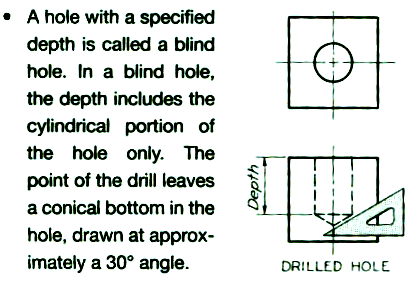
61 Case 3
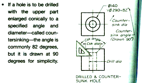
62 Case 4

63 Case 5
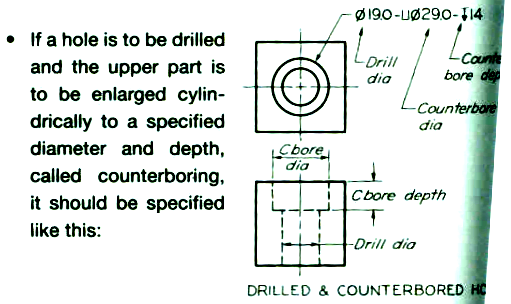
64 Case 6
65 5-37 Runouts: Case 1 Small curves called runouts (i.e., end of rounds) are used to represent fillets that connect with plane surfaces tangent to cylinders, as shown below. The runouts, labeled F, should have a radius equal to that of the fillet and a curvature of about 1/8 of a circle, as shown in (d).
66 Case 2
67 Case 3
68 The runouts from different filleted intersections will appear differently due to the shapes of the horizontal intersecting members. See examples below.
69 In figures (e) and (f) the runouts differ because the top surface of the web is flat in fig. (e), while the top surface of the web in (f) is considerably rounded. When two different sizes of fillets intersect, the direction of runout is dictated by the larger fillet as in figs. (g) and (j).
70 5-38 Conventional Edges Rounded and filleted intersections eliminate sharp edges and can make it difficult to present the shape clearly. In some cases, as shown in Fig. (a), the true projection may be misleading. Added lines depicting rounded and filleted edges, as shown in Figs. (b) and (c), give a clear representation, even though it is not a true projection. Project the added lines from the intersections of the surfaces as if the rounded and filleted were not present.

71 Preferred 1

72 Preferred 2
73 Figures below show the top views for each given front view. The first set of top views have very few lines, even though they are the true projections. The second set of top views, where lines are added to represent the rounded and filleted edges, are quite clear. Note the use of the small Y s where rounded and filleted edges meet a rough surface. If an edge intersects a finished surface, no Y is shown.
74 5-40 Partial Views A view may not need to be complete, but only need to show what is necessary to clearly describe the object. This is called a partial view and is used to save sketching time. You can use a break line to limit the partial view, as shown in figure (a), or limit a view by the contour of the part shown, as shown in fig. (b). If the view is symmetrical, you can draw a halfview on the one side of the centerline, as shown in Fig. (c), or break out a partial view, as shown in fig. (d). The half-views should be the near side, as shown.
75 When drawing a partial view, do not place a break line where it will coincide with a visible or hidden line, as this may cause the drawing to be misinterpreted. Occasionally the distinctive features of an object are on opposite site. In either complete side view there will be a considerable overlapping of shapes. In cases like this, two side views are often the best solution, as shown in figure below. The views are partial views, and certain visible and hidden lines have been omitted for clarity.
76 5-41 Removed Views A removed view is a complete or partial view removed to another place on the sheet so that it no longer is in direct projection with any other view, as shown below. A removed view may be used to show a feature of the object more clearly, possibly to a larger scale, or to save drawing a complete regular view. A viewing-plane line is used to indicate the part being viewed. The arrows at the corners show the direction of sight. The removed views should be labeled view A-A or view B-B and so on; the letters refer to those placed at the corners of the viewing-plane line.
77 5-44 Right-Hand and Left-Hand Parts Often individual parts function in pairs where opposite parts are similar. But opposite parts can rarely be exactly alike. On sketches and drawings a left-hand is noted as LH, and right-hand part as RH. In figure (a), the part in front of the mirror is a right-hand part, and the imagine shows the left-hand part. No matter how the object is turned, the image will show the LH part. Figures (b) and (c) show the LH and RH drawing of the same object.
78
79 Ordinarily you draw only one of the two opposite parts and label the one that is drawn with a note, such as LH PART SHOWN, RH OPPOSITE. If the opposite-hand is not clear, you should make a separate sketch or drawing to show it clearly and completely.
80 5-45 Revolution Conventions Regular multiview projections are sometimes awkward, confusing, or actually misleading. For instance, figure (a) shows an object that has three triangular ribs, three holes equally spaced in the base, and a key way. The right side view is a regular projection and is not recommended the lower ribs appear in a foreshortened position, the holes do not appear in their true relation to the rim of the base, and the key way is projected as a confusion hidden lines. The conventional method in fig. (c) is preferred because it is simpler to read and requires less time to sketch. Each of the features mentioned has been revolved in the front view to lie along the vertical centerline, from where it is projected to the correct side view.
81 Figures (d) and (e) show regular views of a flange with many small holes. The hidden holes are confusing and take unnecessary time to show. The preferred representation in fig. (f) shows the holes revolved for clarity.
82 Figures below show a regular projection with a confusing foreshortening of the inclined arm. To make the object s symmetry clear, the lower arm is revolved to line up vertically in the front view, shown in fig. (b).
Traditional Drawing Tools
 Engineering Drawing Traditional Drawing Tools DRAWING TOOLS DRAWING TOOLS 1. T-Square 2. Triangles DRAWING TOOLS HB for thick line 2H for thin line 3. Adhesive Tape 4. Pencils DRAWING TOOLS 5. Sandpaper
Freehand Sketching. Sections
 3 Freehand Sketching Sections 3.1 Why Freehand Sketches? 3.2 Freehand Sketching Fundamentals 3.3 Basic Freehand Sketching 3.4 Advanced Freehand Sketching Key Terms Objectives Explain why freehand sketching
Sectional drawings cutting plane
 Section Views Section Views The technique called section views is used to improve the visualization of new designs, clarify multiview drawings and facilitate the dimensioning of drawings. For mechanical
Introduction to CATIA V5
 Introduction to CATIA V5 Release 16 (A Hands-On Tutorial Approach) Kirstie Plantenberg University of Detroit Mercy SDC PUBLICATIONS Schroff Development Corporation www.schroff.com www.schroff-europe.com
Section. Tolerances. Aluminum Extrusion Manual. 4th Edition
 Section 8 Tolerances Aluminum Extrusion Manual 4th Edition Section 8 How straight is straight enough? How flat is flat enough? How uniform must a wall thickness be in order to be acceptable? These are
Technical Drawing Specifications Resource A guide to support VCE Visual Communication Design study design 2013-17
 A guide to support VCE Visual Communication Design study design 2013-17 1 Contents INTRODUCTION The Australian Standards (AS) Key knowledge and skills THREE-DIMENSIONAL DRAWING PARALINE DRAWING Isometric
Angle - a figure formed by two rays or two line segments with a common endpoint called the vertex of the angle; angles are measured in degrees
 Angle - a figure formed by two rays or two line segments with a common endpoint called the vertex of the angle; angles are measured in degrees Apex in a pyramid or cone, the vertex opposite the base; in
Modeling Curved Surfaces
 Modeling Cylindrical and Curved Theory Views of Cylinders Contour Lines Extruded Surfaces Revolved Surfaces & Cutouts Profile Shape Axis of Revolution Swept Surfaces & Cutouts Profile Shape Path Curves
DRAFTING MANUAL. Gears (Bevel and Hypoid) Drafting Practice
 Drafting Practice") Page 1 1.0 General This section provides the basis for uniformity in engineering gears drawings and their technical data for gears with intersecting axes (bevel gears), and nonparallel, nonintersecting
Page 1 1.0 General This section provides the basis for uniformity in engineering gears drawings and their technical data for gears with intersecting axes (bevel gears), and nonparallel, nonintersecting
Angles that are between parallel lines, but on opposite sides of a transversal.
 GLOSSARY Appendix A Appendix A: Glossary Acute Angle An angle that measures less than 90. Acute Triangle Alternate Angles A triangle that has three acute angles. Angles that are between parallel lines,
Shape Dictionary YR to Y6
 Shape Dictionary YR to Y6 Guidance Notes The terms in this dictionary are taken from the booklet Mathematical Vocabulary produced by the National Numeracy Strategy. Children need to understand and use
Pro/ENGINEER Wildfire 4.0 Basic Design
 Introduction Datum features are non-solid features used during the construction of other features. The most common datum features include planes, axes, coordinate systems, and curves. Datum features do
ME 111: Engineering Drawing
 ME 111: Engineering Drawing Lecture # 14 (10/10/2011) Development of Surfaces http://www.iitg.ernet.in/arindam.dey/me111.htm http://www.iitg.ernet.in/rkbc/me111.htm http://shilloi.iitg.ernet.in/~psr/ Indian
Chapter 1. Creating Sketches in. the Sketch Mode-I. Evaluation chapter. Logon to www.cadcim.com for more details. Learning Objectives
 Chapter 1 Creating Sketches in Learning Objectives the Sketch Mode-I After completing this chapter you will be able to: Use various tools to create a geometry. Dimension a sketch. Apply constraints to
Activity Set 4. Trainer Guide
 Geometry and Measurement of Solid Figures Activity Set 4 Trainer Guide Mid_SGe_04_TG Copyright by the McGraw-Hill Companies McGraw-Hill Professional Development GEOMETRY AND MEASUREMENT OF SOLID FIGURES
Technical Drawing. MEC1000 Spring 2006 Instructor: David Anderson
 Technical Drawing MEC1000 Spring 2006 Instructor: David Anderson Topics Drawing Views Drawing Standards Best Practices Creating Drawings in SolidWorks Spring 2006 MEC1000 Technical Drawing - D. Anderson
Selecting the Best Approach to Teach 3D Modeling to Technical College Engineering
 Paper ID #12358 Selecting the Best Approach to Teach 3D Modeling to Technical College Engineering Students Dr. Farzin Heidari, Texas A&M University, Kingsville c American Society for Engineering Education,
Geometry Notes PERIMETER AND AREA
 Perimeter and Area Page 1 of 57 PERIMETER AND AREA Objectives: After completing this section, you should be able to do the following: Calculate the area of given geometric figures. Calculate the perimeter
SAMPLE TEST PAPER - I
 SCHEME E SAMPLE TEST PAPER - I Course Name : Mechanical Engineering Group Course Code : AE/PG/PT/ME/MH/FE Semester : Third Subject : Mechanical Engineering Drawing 12042 Time : 90 Minutes Marks: 25 Instruction:
DWG 001. Blueprint Reading. Line Standards Drawing Symbols. Instructor Guide
 DWG 001 Blueprint Reading Line Standards Drawing Symbols Instructor Guide Module Purpose Introduction The purpose of the Blueprint Reading modules is to introduce students to production drawings and blueprint
Pro/ENGINEER Wildfire 5.0 Introduction to Surface Modeling
 Introduction Several advanced surface types are available as listed below. Variable Section Sweep Boundary Blend Section to Surfaces Blend Surface to Surface Blend A surface is created by sweeping a single
West Sound Technical Skills Center 101 National Avenue N. Bremerton WA 98312
 West Sound Technical Skills Center 101 National Avenue N. Bremerton WA 98312 Instructor: Tony Sharpe Phone: 360-473-0585 Fax: 360-478-5090 Email: [email protected] Hours: 7:30 a.m. 3:00
OD1641 PRINCIPLES OF DRAFTING AND SHOP DRAWINGS
 SUBCOURSE OD1641 EDITION 8 PRINCIPLES OF DRAFTING AND SHOP DRAWINGS US ARMY REPAIR SHOP TECHNICIAN WARRANT OFFICER ADVANCED CORRESPONDENCE COURSE MOS/SKILL LEVEL: 441A PRINCIPLES OF DRAFTING AND SHOP
Geometry Chapter 1. 1.1 Point (pt) 1.1 Coplanar (1.1) 1.1 Space (1.1) 1.2 Line Segment (seg) 1.2 Measure of a Segment
 1.1 Coplanar (1.1) 1.1 Space (1.1) 1.2 Line Segment (seg) 1.2 Measure of a Segment") Geometry Chapter 1 Section Term 1.1 Point (pt) Definition A location. It is drawn as a dot, and named with a capital letter. It has no shape or size. undefined term 1.1 Line A line is made up of points
Geometry Chapter 1 Section Term 1.1 Point (pt) Definition A location. It is drawn as a dot, and named with a capital letter. It has no shape or size. undefined term 1.1 Line A line is made up of points
Algebra Geometry Glossary. 90 angle
 lgebra Geometry Glossary 1) acute angle an angle less than 90 acute angle 90 angle 2) acute triangle a triangle where all angles are less than 90 3) adjacent angles angles that share a common leg Example:
CATIA Wireframe & Surfaces TABLE OF CONTENTS
 TABLE OF CONTENTS Introduction... 1 Wireframe & Surfaces... 2 Pull Down Menus... 3 Edit... 3 Insert... 4 Tools... 6 Generative Shape Design Workbench... 7 Bottom Toolbar... 9 Tools... 9 Analysis... 10
Making 3D Threads in Feature Based Solid Modelers
 Making 3D Threads in Feature Based Solid Modelers THREAD BASICS Making true geometric threads in feature-based solid modelers is a fairly straightforward process and can be handled using several different
Understand the Sketcher workbench of CATIA V5.
 Chapter 1 Drawing Sketches in Learning Objectives the Sketcher Workbench-I After completing this chapter you will be able to: Understand the Sketcher workbench of CATIA V5. Start a new file in the Part
ISO 1101 Geometrical product specifications (GPS) Geometrical tolerancing Tolerances of form, orientation, location and run-out
 Geometrical tolerancing Tolerances of form, orientation, location and run-out") INTERNATIONAL STANDARD ISO 1101 Third edition 2012-04-15 Geometrical product specifications (GPS) Geometrical tolerancing Tolerances of form, orientation, location and run-out Spécification géométrique
INTERNATIONAL STANDARD ISO 1101 Third edition 2012-04-15 Geometrical product specifications (GPS) Geometrical tolerancing Tolerances of form, orientation, location and run-out Spécification géométrique
12-1 Representations of Three-Dimensional Figures
 Connect the dots on the isometric dot paper to represent the edges of the solid. Shade the tops of 12-1 Representations of Three-Dimensional Figures Use isometric dot paper to sketch each prism. 1. triangular
Wallingford Public Schools - HIGH SCHOOL COURSE OUTLINE
 Wallingford Public Schools - HIGH SCHOOL COURSE OUTLINE Course Title: Computer Aided Drafting & Design Course Number: 7163 Department: Career and Technical Education Grade(s): 9-12 Level(s): Academic Credit:
16 Circles and Cylinders
 16 Circles and Cylinders 16.1 Introduction to Circles In this section we consider the circle, looking at drawing circles and at the lines that split circles into different parts. A chord joins any two
Geometry and Measurement
 The student will be able to: Geometry and Measurement 1. Demonstrate an understanding of the principles of geometry and measurement and operations using measurements Use the US system of measurement for
Copyright 2011 Casa Software Ltd. www.casaxps.com. Centre of Mass
 Centre of Mass A central theme in mathematical modelling is that of reducing complex problems to simpler, and hopefully, equivalent problems for which mathematical analysis is possible. The concept of
Chapter 8 Geometry We will discuss following concepts in this chapter.
 Mat College Mathematics Updated on Nov 5, 009 Chapter 8 Geometry We will discuss following concepts in this chapter. Two Dimensional Geometry: Straight lines (parallel and perpendicular), Rays, Angles
Technical Drawing. Dr. Anwar Abu-Zarifa. Dr. Anwar Abu-Zarifa. Islamic University Gaza. Industrial Engineering Department 1
 Technical Drawing الرسم الھندسي Dr. Anwar Abu-Zarifa Dr. Anwar Abu-Zarifa. Islamic University Gaza. Industrial Engineering Department 1 Office: IT Building,Room: I413 OfficeHrs: 12:00 13:00(So,Tue,We)
SolidWorks Tutorial 4 CANDLESTICK
 SolidWorks Tutorial 4 CANDLESTICK Candlestick In this tutorial you will make a simple container and a candlestick out of sheetmetal. You will learn about working with sheet metal in SolidWorks. We will
Area of Parallelograms (pages 546 549)
") A Area of Parallelograms (pages 546 549) A parallelogram is a quadrilateral with two pairs of parallel sides. The base is any one of the sides and the height is the shortest distance (the length of a perpendicular
A Area of Parallelograms (pages 546 549) A parallelogram is a quadrilateral with two pairs of parallel sides. The base is any one of the sides and the height is the shortest distance (the length of a perpendicular
1. Kyle stacks 30 sheets of paper as shown to the right. Each sheet weighs about 5 g. How can you find the weight of the whole stack?
 Prisms and Cylinders Answer Key Vocabulary: cylinder, height (of a cylinder or prism), prism, volume Prior Knowledge Questions (Do these BEFORE using the Gizmo.) [Note: The purpose of these questions is
Name Class. Date Section. Test Form A Chapter 11. Chapter 11 Test Bank 155
 Chapter Test Bank 55 Test Form A Chapter Name Class Date Section. Find a unit vector in the direction of v if v is the vector from P,, 3 to Q,, 0. (a) 3i 3j 3k (b) i j k 3 i 3 j 3 k 3 i 3 j 3 k. Calculate
Reflection and Refraction
 Equipment Reflection and Refraction Acrylic block set, plane-concave-convex universal mirror, cork board, cork board stand, pins, flashlight, protractor, ruler, mirror worksheet, rectangular block worksheet,
The University of the State of New York REGENTS HIGH SCHOOL EXAMINATION GEOMETRY. Wednesday, January 29, 2014 9:15 a.m. to 12:15 p.m.
 GEOMETRY The University of the State of New York REGENTS HIGH SCHOOL EXAMINATION GEOMETRY Wednesday, January 29, 2014 9:15 a.m. to 12:15 p.m., only Student Name: School Name: The possession or use of any
Isometric Axes: The lines AB, AD and AE meeting at a point A and making an angle of 120 o with each other are termed isometric axes
 ISOMTRI PROJTION When a solid is resting in its simple position, the front or top view, taken separately, gives an incomplete idea of the form of the object. When the solid is tilted from its simple position
Map Patterns and Finding the Strike and Dip from a Mapped Outcrop of a Planar Surface
 Map Patterns and Finding the Strike and Dip from a Mapped Outcrop of a Planar Surface Topographic maps represent the complex curves of earth s surface with contour lines that represent the intersection
CHAPTER 8, GEOMETRY. 4. A circular cylinder has a circumference of 33 in. Use 22 as the approximate value of π and find the radius of this cylinder.
 TEST A CHAPTER 8, GEOMETRY 1. A rectangular plot of ground is to be enclosed with 180 yd of fencing. If the plot is twice as long as it is wide, what are its dimensions? 2. A 4 cm by 6 cm rectangle has
UNESCO-NIGERIA TECHNICAL & VOCATIONAL EDUCATION REVITALISATION PROJECT-PHASE II NATIONAL DIPLOMA IN BUILDING TECHNOLOGY TECHNICAL DRAWING
 UNESCO-NIGERIA TECHNICAL & VOCATIONAL EDUCATION REVITALISATION PROJECT-PHASE II NATIONAL DIPLOMA IN BUILDING TECHNOLOGY TECHNICAL DRAWING COURSE CODE: BLD 107 YEAR I- SE MESTER I THEORY/PRACTICAL Version
Designing and Drawing a Sprocket Visualizing ideas through the creation of CAD solid models is a key engineering skill.
 05 Webster St. Hanover Massachusetts 0339 Tel. 78 878 5 Fax 78 878 6708 Designing and Drawing a Sprocket Visualizing ideas through the creation of CAD solid models is a key engineering skill. The following
CATIA Functional Tolerancing & Annotation TABLE OF CONTENTS
 TABLE OF CONTENTS Introduction...1 Functional Tolerancing and Annotation...2 Pull-down Menus...3 Insert...3 Functional Tolerancing and Annotation Workbench...4 Bottom Toolbar Changes...5 3D Grid Toolbar...5
SolidWorks Implementation Guides. Sketching Concepts
 SolidWorks Implementation Guides Sketching Concepts Sketching in SolidWorks is the basis for creating features. Features are the basis for creating parts, which can be put together into assemblies. Sketch
Geometry Progress Ladder
 Geometry Progress Ladder Maths Makes Sense Foundation End-of-year objectives page 2 Maths Makes Sense 1 2 End-of-block objectives page 3 Maths Makes Sense 3 4 End-of-block objectives page 4 Maths Makes
SpaceClaim Introduction Training Session. A SpaceClaim Support Document
 SpaceClaim Introduction Training Session A SpaceClaim Support Document In this class we will walk through the basic tools used to create and modify models in SpaceClaim. Introduction We will focus on:
SURFACE AREA AND VOLUME
 SURFACE AREA AND VOLUME In this unit, we will learn to find the surface area and volume of the following threedimensional solids:. Prisms. Pyramids 3. Cylinders 4. Cones It is assumed that the reader has
39 Symmetry of Plane Figures
 39 Symmetry of Plane Figures In this section, we are interested in the symmetric properties of plane figures. By a symmetry of a plane figure we mean a motion of the plane that moves the figure so that
11.1. Objectives. Component Form of a Vector. Component Form of a Vector. Component Form of a Vector. Vectors and the Geometry of Space
 11 Vectors and the Geometry of Space 11.1 Vectors in the Plane Copyright Cengage Learning. All rights reserved. Copyright Cengage Learning. All rights reserved. 2 Objectives! Write the component form of
Modeling Tools Objectives. Sweeps and Lofts. Loft Feature
 Modeling Tools Objectives When you complete this module, you will be able to recognize the more advanced modeling tools in Solid Edge as well as the tools that require more input than typical Solid Edge
TECHNICAL DRAWING (67)
") TECHNICAL DRAWING (67) (Candidates offering Technical Drawing Applications are not eligible to offer Technical Drawing.) Aims: 1. To develop competence among the students to pursue technical courses like
TECHNICAL DRAWING (67) (Candidates offering Technical Drawing Applications are not eligible to offer Technical Drawing.) Aims: 1. To develop competence among the students to pursue technical courses like
56 questions (multiple choice, check all that apply, and fill in the blank) The exam is worth 224 points.
 The exam is worth 224 points.") 6.1.1 Review: Semester Review Study Sheet Geometry Core Sem 2 (S2495808) Semester Exam Preparation Look back at the unit quizzes and diagnostics. Use the unit quizzes and diagnostics to determine which
6.1.1 Review: Semester Review Study Sheet Geometry Core Sem 2 (S2495808) Semester Exam Preparation Look back at the unit quizzes and diagnostics. Use the unit quizzes and diagnostics to determine which
Drawing an Approximate Representation of an Involute Spur Gear Tooth Project Description
 Drawing an Approximate Representation of an Involute Spur Gear Tooth Project Description Create a solid model and a working drawing of the 24 pitch gears specified below. It is only necessary to create
SolidWorks Tutorial 3 MAGNETIC BLOCK
 SolidWorks Tutorial 3 MAGNETIC BLOCK Magnetic Block In this exercise you will make a magnetic block. To do so, you will create a few parts, which you will assemble. You will learn the following new applications
Introduction to Autodesk Inventor for F1 in Schools
 Introduction to Autodesk Inventor for F1 in Schools F1 in Schools Race Car In this course you will be introduced to Autodesk Inventor, which is the centerpiece of Autodesk s digital prototyping strategy
WORKBOOK MODELING OF MULTI- MEMBER MACHINES
 WORKBOOK MODELING OF MULTI- MEMBER MACHINES LUBLIN 2014 0 Author: Mirosław Ferdynus Desktop publishing: Mirosław Ferdynus Technical editor: Mirosław Ferdynus Figures: Mirosław Ferdynus Cover and graphic
1. A plane passes through the apex (top point) of a cone and then through its base. What geometric figure will be formed from this intersection?
 of a cone and then through its base. What geometric figure will be formed from this intersection?") Student Name: Teacher: Date: District: Description: Miami-Dade County Public Schools Geometry Topic 7: 3-Dimensional Shapes 1. A plane passes through the apex (top point) of a cone and then through its
Student Name: Teacher: Date: District: Description: Miami-Dade County Public Schools Geometry Topic 7: 3-Dimensional Shapes 1. A plane passes through the apex (top point) of a cone and then through its
Procedure: Geometrical Optics. Theory Refer to your Lab Manual, pages 291 294. Equipment Needed
 Theory Refer to your Lab Manual, pages 291 294. Geometrical Optics Equipment Needed Light Source Ray Table and Base Three-surface Mirror Convex Lens Ruler Optics Bench Cylindrical Lens Concave Lens Rhombus
3D Drawing. Single Point Perspective with Diminishing Spaces
 3D Drawing Single Point Perspective with Diminishing Spaces The following document helps describe the basic process for generating a 3D representation of a simple 2D plan. For this exercise we will be
SolidWorks: Mirror, Revolve, and. Introduction to Robotics
 SolidWorks: Mirror, Revolve, and Circular Pattern Introduction to Robotics Let s Review At this point we have learned the following: Extrude Boss/Base Extruded Cut Adding Relations and Dimensions Linear
Geometry: Unit 1 Vocabulary TERM DEFINITION GEOMETRIC FIGURE. Cannot be defined by using other figures.
 Geometry: Unit 1 Vocabulary 1.1 Undefined terms Cannot be defined by using other figures. Point A specific location. It has no dimension and is represented by a dot. Line Plane A connected straight path.
Mensuration. The shapes covered are 2-dimensional square circle sector 3-dimensional cube cylinder sphere
 Mensuration This a mixed selection of worksheets on a standard mathematical topic. A glance at each will be sufficient to determine its purpose and usefulness in any given situation. These notes are intended
SOLIDWORKS: SKETCH RELATIONS
 Sketch Feature: The shape or topology of the initial sketch or model is important, but exact geometry and dimensions of the initial sketched shapes are NOT. It recommended to work in the following order:
The University of the State of New York REGENTS HIGH SCHOOL EXAMINATION GEOMETRY. Thursday, January 26, 2012 9:15 a.m. to 12:15 p.m.
 GEOMETRY The University of the State of New York REGENTS HIGH SCHOOL EXMINTION GEOMETRY Thursday, January 26, 2012 9:15 a.m. to 12:15 p.m., only Student Name: School Name: Print your name and the name
9 Area, Perimeter and Volume
 9 Area, Perimeter and Volume 9.1 2-D Shapes The following table gives the names of some 2-D shapes. In this section we will consider the properties of some of these shapes. Rectangle All angles are right
Basic AutoSketch Manual
 Basic AutoSketch Manual Instruction for students Skf-Manual.doc of 3 Contents BASIC AUTOSKETCH MANUAL... INSTRUCTION FOR STUDENTS... BASIC AUTOSKETCH INSTRUCTION... 3 SCREEN LAYOUT... 3 MENU BAR... 3 FILE
Line Segments, Rays, and Lines
 HOME LINK Line Segments, Rays, and Lines Family Note Help your child match each name below with the correct drawing of a line, ray, or line segment. Then observe as your child uses a straightedge to draw
Geometry Review Flash Cards
 point is like a star in the night sky. However, unlike stars, geometric points have no size. Think of them as being so small that they take up zero amount of space. point may be represented by a dot on
Geometry Notes VOLUME AND SURFACE AREA
 Volume and Surface Area Page 1 of 19 VOLUME AND SURFACE AREA Objectives: After completing this section, you should be able to do the following: Calculate the volume of given geometric figures. Calculate
1. A student followed the given steps below to complete a construction. Which type of construction is best represented by the steps given above?
 1. A student followed the given steps below to complete a construction. Step 1: Place the compass on one endpoint of the line segment. Step 2: Extend the compass from the chosen endpoint so that the width
E XPLORING QUADRILATERALS
 E XPLORING QUADRILATERALS E 1 Geometry State Goal 9: Use geometric methods to analyze, categorize and draw conclusions about points, lines, planes and space. Statement of Purpose: The activities in this
Everyday Mathematics. Grade 4 Grade-Level Goals CCSS EDITION. Content Strand: Number and Numeration. Program Goal Content Thread Grade-Level Goal
 Content Strand: Number and Numeration Understand the Meanings, Uses, and Representations of Numbers Understand Equivalent Names for Numbers Understand Common Numerical Relations Place value and notation
The University of the State of New York REGENTS HIGH SCHOOL EXAMINATION GEOMETRY. Tuesday, August 13, 2013 8:30 to 11:30 a.m., only.
 GEOMETRY The University of the State of New York REGENTS HIGH SCHOOL EXAMINATION GEOMETRY Tuesday, August 13, 2013 8:30 to 11:30 a.m., only Student Name: School Name: The possession or use of any communications
An introduction to 3D draughting & solid modelling using AutoCAD
 An introduction to 3D draughting & solid modelling using AutoCAD Faculty of Technology University of Plymouth Drake Circus Plymouth PL4 8AA These notes are to be used in conjunction with the AutoCAD software
Grade 8 Mathematics Geometry: Lesson 2
 Grade 8 Mathematics Geometry: Lesson 2 Read aloud to the students the material that is printed in boldface type inside the boxes. Information in regular type inside the boxes and all information outside
GEOMETRY CONCEPT MAP. Suggested Sequence:
 CONCEPT MAP GEOMETRY August 2011 Suggested Sequence: 1. Tools of Geometry 2. Reasoning and Proof 3. Parallel and Perpendicular Lines 4. Congruent Triangles 5. Relationships Within Triangles 6. Polygons
ABERLINK 3D MKIII MEASUREMENT SOFTWARE
 ABERLINK 3D MKIII MEASUREMENT SOFTWARE PART 1 (MANUAL VERSION) COURSE TRAINING NOTES ABERLINK LTD. EASTCOMBE GLOS. GL6 7DY UK INDEX 1.0 Introduction to CMM measurement...4 2.0 Preparation and general hints
Microsoft Excel 2010 Charts and Graphs
 Microsoft Excel 2010 Charts and Graphs Email: [email protected] Web Page: http://training.health.ufl.edu Microsoft Excel 2010: Charts and Graphs 2.0 hours Topics include data groupings; creating
Duplicating Segments and Angles
 CONDENSED LESSON 3.1 Duplicating Segments and ngles In this lesson, you Learn what it means to create a geometric construction Duplicate a segment by using a straightedge and a compass and by using patty
Snap to It with CorelDRAW 12! By Steve Bain
 Snap to It with CorelDRAW 12! By Steve Bain If you've ever fumbled around trying to align your cursor to something, you can bid this frustrating task farewell. CorelDRAW 12 object snapping has been re-designed
The University of the State of New York REGENTS HIGH SCHOOL EXAMINATION GEOMETRY. Wednesday, January 28, 2015 9:15 a.m. to 12:15 p.m.
 GEOMETRY The University of the State of New York REGENTS HIGH SCHOOL EXAMINATION GEOMETRY Wednesday, January 28, 2015 9:15 a.m. to 12:15 p.m., only Student Name: School Name: The possession or use of any
Introduction to Autodesk Inventor for F1 in Schools
 F1 in Schools race car Introduction to Autodesk Inventor for F1 in Schools In this course you will be introduced to Autodesk Inventor, which is the centerpiece of Autodesk s Digital Prototyping strategy
MD5-26 Stacking Blocks Pages 115 116
 MD5-26 Stacking Blocks Pages 115 116 STANDARDS 5.MD.C.4 Goals Students will find the number of cubes in a rectangular stack and develop the formula length width height for the number of cubes in a stack.
Tutorial: 3D Pipe Junction Using Hexa Meshing
 Tutorial: 3D Pipe Junction Using Hexa Meshing Introduction In this tutorial, you will generate a mesh for a three-dimensional pipe junction. After checking the quality of the first mesh, you will create
rarecorvettes.com, [email protected], (831) 475-4442 Pacific Time Zone
 475-4442 Pacific Time Zone") INTRODUCTION TO WHEEL ALIGNMENT A SHORT COURSE ON WHEEL ALIGNMENT, FRONT AND REAR PREPARED FOR THE N.C.R.S. NATIONAL CONVENTION JUNE 29 TO JULY 5, 2012 by: JOE CALCAGNO, RARE CORVETTES rarecorvettes.com,
INTRODUCTION TO WHEEL ALIGNMENT A SHORT COURSE ON WHEEL ALIGNMENT, FRONT AND REAR PREPARED FOR THE N.C.R.S. NATIONAL CONVENTION JUNE 29 TO JULY 5, 2012 by: JOE CALCAGNO, RARE CORVETTES rarecorvettes.com,
DRAWING INSTRUMENTS AND THEIR USES
 Chapter - A DRAWING INSTRUMENTS AND THEIR USES Drawing Instruments are used to prepare neat and accurate Drawings. To a greater extent, the accuracy of the Drawings depend on the quality of instruments
Learning Autodesk. Modeling, Analysis and Animation SDC. Randy H. Shih. Better Textbooks. Lower Prices. PUBLICATIONS www.sdcpublications.
 Learning Autodesk Inventor 2012 Modeling, Analysis and Animation Randy H. Shih SDC Better Textbooks. Lower Prices. PUBLICATIONS www.sdcpublications.com Schroff Development Corporation Visit the following
Lesson 26: Reflection & Mirror Diagrams
 Lesson 26: Reflection & Mirror Diagrams The Law of Reflection There is nothing really mysterious about reflection, but some people try to make it more difficult than it really is. All EMR will reflect
Working Drawing and Assemblies. Chapter 10
 Working Drawing and Assemblies Chapter 10 Objectives 1.Define working drawings. 2. Describe how working drawings are used in industry. 3. List the major components of a complete set of working drawings.
TABLE OF CONTENTS. INTRODUCTION... 5 Advance Concrete... 5 Where to find information?... 6 INSTALLATION... 7 STARTING ADVANCE CONCRETE...
 Starting Guide TABLE OF CONTENTS INTRODUCTION... 5 Advance Concrete... 5 Where to find information?... 6 INSTALLATION... 7 STARTING ADVANCE CONCRETE... 7 ADVANCE CONCRETE USER INTERFACE... 7 Other important
CATIA Drafting TABLE OF CONTENTS
 TABLE OF CONTENTS Introduction...1 Drafting...2 Drawing Screen...3 Pull-down Menus...4 File...4 Edit...5 View...6 Insert...7 Tools...8 Drafting Workbench...9 Views and Sheets...9 Dimensions and Annotations...10
The GED math test gives you a page of math formulas that
 Math Smart 643 The GED Math Formulas The GED math test gives you a page of math formulas that you can use on the test, but just seeing the formulas doesn t do you any good. The important thing is understanding
Platonic Solids. Some solids have curved surfaces or a mix of curved and flat surfaces (so they aren't polyhedra). Examples:
. Examples:") Solid Geometry Solid Geometry is the geometry of three-dimensional space, the kind of space we live in. Three Dimensions It is called three-dimensional or 3D because there are three dimensions: width,
Solid Geometry Solid Geometry is the geometry of three-dimensional space, the kind of space we live in. Three Dimensions It is called three-dimensional or 3D because there are three dimensions: width,
Optical Illusions Essay Angela Wall EMAT 6690
 Optical Illusions Essay Angela Wall EMAT 6690! Optical illusions are images that are visually perceived differently than how they actually appear in reality. These images can be very entertaining, but
Conjectures. Chapter 2. Chapter 3
 Conjectures Chapter 2 C-1 Linear Pair Conjecture If two angles form a linear pair, then the measures of the angles add up to 180. (Lesson 2.5) C-2 Vertical Angles Conjecture If two angles are vertical