City of St. Petersburg Municipal Pier Building Structure and Substructure Evaluation City Project Number:
|
|
|
- Silas Ferdinand Blair
- 7 years ago
- Views:
Transcription
1 Final Report for
2 August 8, 2014 City of St. Petersburg Municipal Pier Building Structure and Substructure Evaluation Executive Summary This report evaluates the existing condition of the Municipal Pier building structure (and supporting substructure caissons) in St. Petersburg, Florida. In order to determine the feasibility of refurbishing the building by reusing its current structural components, assessment included field review, materials testing, and evaluation of previous documentation and studies. Based on the findings of our team, the following conclusions are presented: Current building code requirements dictate a significant increase in design wind loading well above that of the original design which could require strengthening or reconstruction of the existing structural system for compliance. Current building code requirements may impede usage of the first floor of a refurbished building due to flood elevation design requirements. Corrosion testing and analysis showed the existing steel structure related to the building has limited corrosion activity. The reinforced concrete components of the building structure have random areas of deterioration related to moisture and chloride intrusion. Based on available data, the steel H piles of the caisson substructure appear to have limited chloride exposure. Consideration of access for necessary reconstruction of the supporting first floor structural elements (that were part of the original pier design) would be a significant issue due to interference from the surrounding structure. An extension of the design life of the building structure for an additional 75 years would greatly exceed that of similar coastal structures but could be achieved with repairs, reconstruction, cathodic protection systems for steel components, any strengthening requirements for the buildings structural systems, and first floor flood elevation modifications for building code compliance. i
3 Table of Contents Executive Summary... i Table of Contents... ii List of Figures... iii List of Tables... iii 1.0 Introduction History Scope of Services Documentation Condition Survey Structure Description Site Visit Selective Demolition Structural Observations Elevator Shaft Structural Observations Wind Loading Analysis Lightning Protection System Corrosion Investigation Limits of Investigation Corrosion Investigation Results Structural Conclusion Recommendations Appendix A 27 Appendix B 29 ii
4 List of Figures Figure 1: Inverted Pyramid Page 1 Figure 2: Caisson Layout Page 3 Figure 3: Demolition Page 4 Figure 4: Concrete Sample A Page 4 Figure 5: Concrete Sample B Page 4 Figure 6: Concrete Sample C Page 5 Figure 7: Concrete Sample C Page 5 Figure 8: Concrete Sample C Page 5 Figure 9: Concrete Sample D Page 6 Figure 10: Concrete Sample D Page 6 Figure 11: Concrete Sample D Page 6 Figure 12: 5 th Floor Plan View Page 10 Figure 13: 5 th Floor Damage SW Corner Page 12 Figure 14: Typical Deterioration Page 12 Figure 15: Elevator Pits Page 14 Figure 16: Exterior Damage Page 14 Figure 17: Exterior Damage Page 15 Figure 18: Exterior Damage SW Corner Page 16 Figure 19: Exterior Damage SW Corner Page 17 Figure 20: Chloride Content Results Page 19 Figure 21: Carbonation Depth Results Page 20 List of Tables Table 1: Design Wind Pressures Page 8 Table 2: Location of Powder Samples Page 11 Table 3: Caisson Identification for VCS and McLaren Page 21 iii
5 Introduction 1.1 History The St. Petersburg Municipal Pier (The Pier) was constructed in 1926 and consists of approximately 1,400 feet by 100 feet of approach spans and a 420 foot by 300 foot pier head at its eastern end. A five story inverted pyramid building (Figure 1), the primary subject of this report, was built within the pier head in Additions consisting of a first level retail space build out and an exterior west elevator were constructed in Figure 1: Inverted pyramid On May 31, 2013 the pier was closed to all commerce and non-essential vehicular traffic due to deterioration of primary structural components throughout the approach spans and portions of the pier head. The design of a replacement pier, called The Lens, had been approved by the St. Petersburg City Council and was in the developmental stages before a citizen-driven referendum in August, 2013 halted the progress. Upon taking office in 2014, Mayor Rick Kriseman asked that security fences be removed and that the pier approaches and pier head be open to the public for pedestrian access, fishing and other related activities. At the time of this report, the pier is open to pedestrian traffic and essential vehicular traffic that is required for pier maintenance but the building remains closed to the public. 1.2 Scope of Services While there is little question that the original pier structural components have reached the end of their useful service life based on previous investigations, there has been recent discussion regarding the possibility of restoring the inverted pyramid and incorporating it into a new pier concept. The Scope of Services required for this report was to perform an inspection of the existing inverted pyramid structure and the foundation elements associated with it and make a recommendation to the City regarding the feasibility of restoration. Specific services performed by the engineering team included: Inspection and evaluation of the inverted pyramid structure Inspection and evaluation of the caissons 1
6 Removal of concrete material for visual inspection of internal components and strength and chloride testing (including repair of the sample excavation sites) Evaluation of current Building Code requirements as compared to the 1973 design code Estimation of the remaining service life of the inverted pyramid structure and foundation Recommendation of measures to extend the service life of the pyramid structure and foundation Prepare of a summary of findings report 1.3 Documentation The following documentation was provided by the City of St. Petersburg (the City): Pier Development Project architectural drawings prepared by Harvard and Jolly, A.I.A., dated March 2, Pier Development Project structural drawings prepared by Erwin Reiss, dated March 2, First Floor Retail Structure & Elevator Addition St. Petersburg Municipal Pier Improvements architectural drawings prepared by Sasaki Associates, Inc., dated March 10, St. Petersburg Municipal Pier Improvements structural drawings prepared by O.E. Olsen & Associates, dated July 23, Saint Petersburg Municipal Pier, Alternatives Study, Parsons Brinckerhoff, May St. Petersburg Pier Existing Caisson Inspection, McLaren Engineering Group, February Environmental Forces Study, McLaren Engineering Group, April Results of Petrographic Examinations and Laboratory Testing of Concrete Cores, Terracon Consultants, Inc., August St. Petersburg Pier Remaining Service Life Caissons and Steel Frame, Karins Engineering Group, Inc., May
7 Condition Survey 2.1 Structure Description The St. Petersburg Municipal Pier was constructed in In 1973 an inverted pyramid structure and four supporting caissons (Figure 2) were added to the pier. In 1986 a fifth caisson supporting an exterior elevator, identified as the west caisson, was added to the pier. Each caisson is comprised of twenty HP14x73 steel piles that are encapsulated in concrete within a steel sheet pile cofferdam that serves as a stay-in-place form. The primary foundation elements of the inverted pyramid and additional elevator are structurally independent of the original pier. The inverted pyramid is comprised of a steel frame encased in concrete for fireproofing, corrosion protection, and strength. The inverted pyramid s first level floor structure Figure 2: Caisson layout consists of a concrete pile/beam/slab system that was constructed with the original pier in The remainder of the main structure consists of wide flange steel beam and column construction. The floor system for the remainder of the structure consists of reinforced cast-in-place (CIP) concrete slabs supported by the wide flange steel beams. 2.2 Site Visit Out team performed a condition survey of The Pier on Tuesday, June 3, The assessment consisted of an exterior perimeter survey accessed from the pier deck and roof of the first floor retail area and included observations of the bottom portion of accessible elevator shafts and tops of caissons in the shafts. The second assessment, June 25, 2014, consisted of selective demolition and a visual survey of the upper portion of the beam on the southwest corner of the structure. The selective demolition was completed by Vector Corrosion Services (VCS) in conjunction with material sampling and testing. Biller Reinhart Structural Group, Inc. (Biller Reinhart) led the structural investigation of the building. 3
8 2.3 Selective Demolition Structural Observations Portions of the concrete encasement were removed from the upper regions of the main beam at the southwest corner of the structure. The purpose of the selective demolition was to expose the underlying steel components and observe the degree of corrosion present. Observations from the selective demolition are as follows: Sample Area A A. Sample Area A was located in the center portion of the bottom of the beam where concrete spalling was observed (Figure 3). Figure 3: Demolition B. The removed portion of the concrete in Sample Area A (Figure 4). C. The markings observed in the bottom flange of the beam were due to tool impact during the removal of the concrete. D. Cracking in the concrete was observed to extend from the surface of the encasement to steel flange. Figure 4: Concrete sample A E. Corrosion of the steel beam flange was not observed in the sample area. F. An isolated portion of the welded wire fabric embedded in the concrete encasement was observed to be corroded. Sample Area B A. Sample Area B was located at the edge of the bottom flange of the beam. Figure 5: Concrete sample B 4
9 B. The removed portion of the concrete in Sample Area B (Figure 5). C. The markings observed in the bottom flange of the beam were due to tool impact during the removal of the concrete. D. Corrosion of the steel beam flange was not observed in the sample area. Sample Area C A. Sample Area C was located at the intersection of the diagonal corner beam and the fifth level perimeter beam. Cracking in the concrete encasement was present at the location of the cracking. B. The removed portion of the concrete (Figure 6). C. The top flange of the exposed perimeter beam (Figure 7). Surficial corrosion of the top flange was observed. D. Minor corrosion of an embedded reinforcement bar was observed above the top flange of the beam. Refer to (Figure 8). E. The cracking in the concrete encasement of the perimeter beam appeared to be occurring where the encasement extended over the face of the observation deck. Neither steel welded wire fabric nor reinforcement bars were observed in this section of the encasement. Such reinforcement is to minimize the widths and extents of cracking in concrete. Figure 6: Concrete sample C Figure 7: Concrete sample C Sample Area D A. Sample Area D was located in the center of the top flange beam. Figure 8: Concrete sample C 5
10 B. The removed portion of the concrete in Sample Area D (Figure 9). C. Corrosion of the steel beam flange was not observed in the sample area (Figure 10). D. The markings observed in the top flange of the beam were due to tool impact during the removal of the concrete. Figure 9: Concrete sample D 2.4 Elevator Shaft Structural Observations Elevators are located above the NW, SW, SE, and W caissons. The elevator pits were used to gain access to the top of the caissons for inspection. Two of the elevator shafts were accessed to observe the structural condition of the tops of the SW and SE caissons as well as the exposed portions of the main column base plates. The observed portions of the tops of the caissons did not appear to evidence significant moisture intrusion along the construction joint between the caisson and the elevator shaft walls thus indicating a reduced potential for corrosion of the caisson (top surface) and elevator shaft components. Additionally, portions of the column base plates had not had a concrete encasement applied, thus allowing for observation of the steel base plates and anchor bolts. The observed anchor bolts and base plates evidenced minor surficial corrosion which has not impacted the strength of these components (Figure 11). Figure 10: Concrete sample D Figure 11: Concrete sample D 6
11 Wind Loading Analysis The drawings indicate that the structure was designed in conformance to the Southern Standard Building Code. The structure was designed in The latest edition of the building code which would have been in effect at the time of construction would have been the 1969 or the 1970 Southern Standard Building Code. Section of both editions of the Southern Standard Building Code outlines the same wind loading design requirements. The structure would have been located in a Southern Coastal Region. The outlined design wind pressures are 25 pounds per square foot (psf) for the portions of the structure that are 30 feet or less in height. The portions of the structure which are between 30 and 50 feet in height were required to be designed for 35 psf. The portions of the structure which are between 51 and 99 feet in height were required to be designed for 45 psf. Based on the original construction drawings, the structure was constructed 9 feet above mean sea level thus 9 feet would be added to the building height for analysis purposes. Since the time of construction of the inverted pyramid structure many editions and revisions have been made to the building codes which govern construction in Florida. Significant changes to wind loading requirements were made after Hurricane Andrew in Two of the current building codes which outline structural requirements are the 2010 Florida Building Code: Building and 2010 Florida Building Code: Existing Building. The 2010 Florida Building Code: Building outlines construction requirements for new construction and for buildings undergoing extensive modifications Florida Building Code: Existing Building outlines requirements of existing structures undergoing various levels of modifications. Section 405 of the Existing Building code classifies Level 3 Alterations as Level 3 alterations apply where the work area exceeds 50 percent of the aggregate area of the building and made within any 12-month period. If the inverted pyramid structure is to be renovated then the respective work area will likely encompass 100% of the structure thus meeting the requirements of the Level 3 alteration. As such Section of the Existing Building code requires that Where more than 30 percent of the total floor and roof areas of the building or structure have been or are proposed to be involved in structural alteration within a 12-month period, the evaluation and analysis shall demonstrate that the altered building or structure complies with the Florida Building Code, Building for wind loading. Therefore the inverted pyramid structure would be required to meet the wind loading criteria in the current Florida Building Code: Building. Section 1609 of the Building Code states that the wind load design criteria shall be in accordance with ASCE 7 Minimum Design Loads for Buildings and Other Structures. To determine design wind pressures for the structure the design wind speeds must first be established. The code outlines four risk categories 7
12 for the determination of a design wind speed when given a structures geographic location. Table of ASCE 7-10 outlines a Risk Category III as Buildings and other structures, not included in Risk Category IV, with potential to cause a substantial economic impact and/or mass disruption of day-today civilian life in the event of failure. Given the purpose of the structure, Biller Reinhart believes that the structure would qualify as a Risk Category III structure as failure of the structure would result in a substantial economic impact due to potential repairs and loss of a tourism generator for the surrounding area. After discussions with City of St. Petersburg officials and in conjunction with the above outlined rational, both Biller Reinhart and the City of St. Petersburg Building Official agree that the Risk Category III classification is the appropriate classification and would be prudent for the long-term design of the structure. Based on a Risk Category III classification, the design wind speed for the structure would be 155 miles per hour. As with the Southern Standard Building Code the current code design wind pressures increase along the height of the structure. Current code increases however are done in 5 feet increments starting at 15 feet and going up to 30 feet and are in 10 foot increments thereafter. Given the design wind speed and assuming the window assemblies of the structure would be upgraded to impact resistant windows, the design wind pressures for the structure per the original and current building codes are as follows: Table 1: Design Wind Pressures Height of Structure (ft) Original Design Pressure (psf) Current Design Pressure (psf) Percent Increase (%) With the substantial increase in design wind pressure loading when comparing current code requirements to original construction load requirements, a detailed analysis of the structure would be required to determine if the existing structure is capable of withstanding the code required design wind pressures. If the analysis indicates that the existing structure is incapable of withstanding the current code requirements, then an extensive strengthening of the connections and components would be necessary for the structure to meet current building code requirements. Strengthening of the steel structure would likely include removal of the concrete beam and column encasements to provide access to the steel 8
13 members and connections, field welding supplemental steel plates and/or sections to the existing members and connections, and possible supplemental steel sections being added to the existing structural steel frame. Lightning Protection System Although an in-depth discussion of lightning protection systems is not within the scope of this report, a brief comment is provided for future consideration of any long-term planned use of the existing building structure. An independent system comprised of external protection should be designed by experienced engineers. This protection may consist of rods, conductor cables, and ground rods to provide a designated path to the ground for lightning. Preventing fire, building material damage, flashes across rooms, destruction of electrical appliances, and injury to occupants is an important part of modern building design in regions subject to high frequency lightning strikes. 9
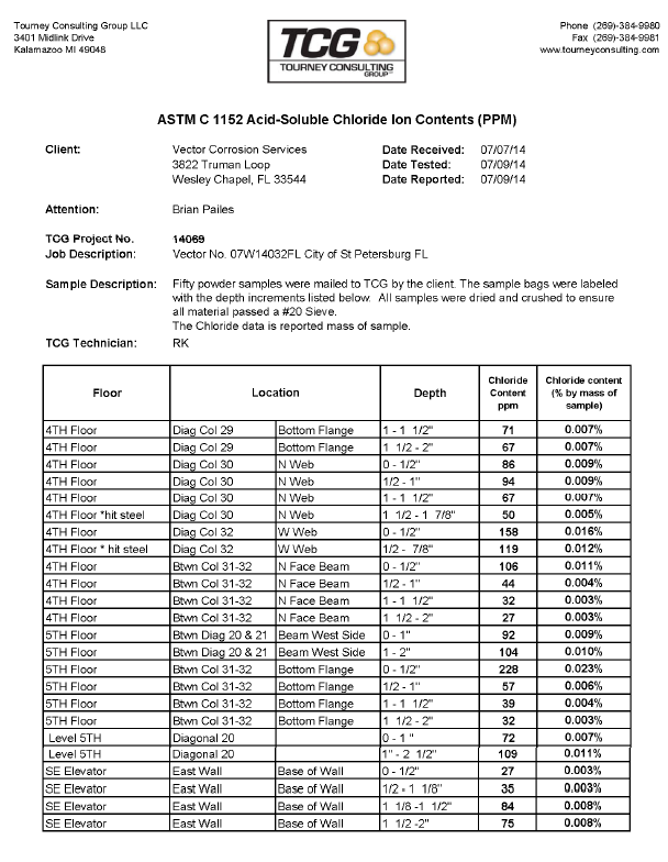
14 Corrosion Investigation 5.1 Limits of Investigation The preliminary corrosion investigation included a complete visual inspection of the inverted pyramid structure, both interior and exterior. The visual inspection included hammer sounding for delaminations in areas in which the structural components were exposed and accessible. Access to the pyramid exterior was limited due to the surrounding pier s condition. The original pier structure is experiencing significant levels of deterioration, therefore load restrictions have been incorporated. As a result, access to the exterior structure above the 2nd floor was limited because an aerial lift large enough to access the upper reaches of the structure was too heavy for the pier. A larger aerial lift was used on the west face of the structure because this area has a greater load carrying capacity. The exterior inspection was completed primarily from the roof of the first floor structure surrounding the pyramid. Each diagonal column of the inverted pyramid structure was given an identification number so that information regarding the diagonals and other structural members could be referenced to a known coordinate system. A plan view of the pyramid s 5th floor is provided along with the label for each diagonal member (Figure 12). The northeast (NE) corner of the structure was set as the zero diagonal and subsequent diagonals numbered sequentially in the clock-wise direction. All exterior components of the pyramid are hereafter referenced to the diagonals and the floor number. Concrete powder samples were collected throughout the Figure 12: 5 th Floor Plan View structure to identify the amount of chloride that had penetrated into the concrete matrix. Concrete powder samples were collected in 14 locations; in the beams, columns, diagonals, and the SE elevator pit (Table 2). The samples were collected primarily on the exterior of the structure, since this was the most susceptible area to chloride contamination. However, several samples were also collected on the interior of the structure to verify that the interior was not exposed to chloride contamination. The powder samples were collected using a hammer drill with a ¾ in. diameter drill bit. The resulting concrete powder was collected and sealed in a plastic bag. The powder samples were collected in ½ inch depth increments starting at the surface and extended 2 inches deep. In two sampling locations (diagonals 30 and 32) steel was encountered prior to reaching the 2 in. depth, therefore drilling was stopped. 10
15 Table 2: Location of powder samples Member Location Reference Diagonal Location Floor Building Face Beam Web Between 8 & 9 2 East Beam Web Between 20 & 21 5 West Beam Web Between 31 & 32 4 North Beam Bottom Flange Between 31 & 32 5 North Column Flange 0 2 Northeast Column Flange 10 2 Southeast Diagonal Bottom Flange 0 2 Northeast Diagonal Bottom Flange 10 2 Southeast Diagonal Bottom Flange 20 5 Southwest Diagonal* Bottom Flange 25 4 West Diagonal Bottom Flange 29 4 West Diagonal + Web 30 4 Northwest Diagonal + Web 32 4 North Elevator Pit* Base of East Wall - 1 Southeast * Interior sample + Encountered steel during collection 11
16 In five locations the concrete cover was removed from around the structural steel to visually inspect the structural steel s condition. Four of the five openings were made in the southwest (SW) corner of the pyramid, diagonal 20, at the 5th floor. The reason this area was a focus is that it showed external signs of advanced deterioration in the form of a coating blister and concrete cracking (Figure 13). This area was also accessible by the aerial lift. The fifth location in which the structural steel was exposed was in the southeast (SE) elevator pit. This location was selected because of the presence of a concrete delamination and potential exposure to seawater from below the pier. 5.2 Corrosion Investigation Results Interior Visual Inspection A complete walk-though of the pyramid interior revealed several instances of water damage, drainage/leak issues, general interior deterioration, and corrosion activity. However, since most of the interior is comprised of partition framing many of the issues noted have little effect on the structure. Typical deterioration found that could pose an issue to the structural frame are presented (Figure 14). Throughout the entire height of the SE stairwell there was apparent water damage and leakage (Figure 14A). The leaks appear to originate at the roof. Figure 13: 5 th Floor damage SW corner Figure 14: Typical deterioration 12
17 Most of the interior structure has a dropped ceiling. Tiles in random locations throughout the building had been removed. This facilitated the visual inspection of a majority of the floor slab soffit. The floor slabs throughout the building appeared in generally good condition except for areas similar to a location on the bottom of the 4th floor (Figure 14-B). Corrosion of the reinforcement and concrete spalling were observed at this location. Buckets and trays were below this damage to catch water. It appears this deterioration is a result of a leak allowing water throughout this area. There are several kitchens throughout the building and all were in a similar state (Figure 14C). Due to its current condition, it is likely that significant amounts of moisture and other materials have reached the slab and walls in areas like this, rendering deterioration likely in the structure around these kitchen areas. The NE stairwell utility closets previously housed equipment for an aquarium attraction, which included tanks, pumps, drains, and piping. The NE stairwell utility closets currently have large amounts of water damage and corrosion staining (Figure 14D). This area is also at risk for chloride intrusion since the aquarium housed saltwater tanks. As a result of the presence of moisture and chlorides, the NE stairwell is an area at risk for corrosion activity. The northwest (NW) stairwell utility closets housed electrical equipment and did not show signs of deterioration like the NE stairwell, due to reduced exposure to moisture Elevator Pit Corrosion Inspection The elevator pits in the NW, SW, and SE were inspected for corrosion related concrete deterioration as the elevator pit above the W caisson was inaccessible. The power to the W elevator had been turned off and the elevator was resting at the lowest level, which restricted access into the pit. Delamination and cracking of the concrete were observed on the floor and walls of the elevator pits (Figure 15). Figure 15A and Figure 15B provide an overview of the elevator pit layout. Figure 15A is the SE elevator pit and Figure 15B is the SW elevator pit. The elevator pits contain mechanical equipment making access more difficult. 13
18 Cracking was observed in the floor of the NW elevator pit (Figure 15C). The NW pit was the most deteriorated of the three elevator pits inspected. The floor had large amounts of cracking and the walls had large areas of delaminated concrete. The deterioration in the SW (Figure 15D and Figure 15E) and SE elevator pits was similar. The walls had areas of delamination that extended up the concrete wall to the concrete masonry unit topping. A common area of concrete delamination was along the corners of the elevator pit. A large primary structural concrete encased steel column is located at the corner of the pit Exterior Visual Corrosion Inspection During the exterior visual inspection several areas of deterioration were identified. Figure 16 and Figure 17 depict the type of damage that was observed. Due to access restrictions, the damage observations are limited to what could be seen from the roof of the first floor. The limited proximity to the structural members restricted the ability to provide an in-depth inspection. Diagonals 33, 34, 35, and 36 all showed signs of transverse cracking along the bottom flange, from the 4th floor to 5th floor (Figure 16A). The cracking appears to have been recoated at some point in the life of the structure. Transverse cracking like this indicates damage as a result of deflection or shrinkage as opposed to corrosion activity. However, if the cracks were left exposed to the exterior environment for a significant amount of time it could allow for the ingress of chlorides and carbon dioxide. This could lead to the initiation of corrosion activity in these areas. Figure 15: Elevator Pits Figure 16: Exterior Damage 14
19 A horizontal crack was identified along the exterior face of the north block out, located between diagonals 33 and 34 (Figure 16B). The interior of this block out contains a walk in refrigerator/freezer. The crack could be the result of corrosion activity due to excess moisture resulting from the refrigerator unit. Areas in the structure which contain large refrigerator/freezer units have the potential to supply the surrounding structure with excess moisture. Moisture infiltration could lead to reinforced concrete deterioration in these areas. Additionally, there is a walkway from the 3rd floor to the W elevator. The bottom of this walkway shows signs of water damage (Figure 16C). Inspection from the interior of the 3 rd floor did not reveal any signs of water damage. A common damage type that was observed on the pyramid structure was horizontal cracking in the concrete encasement of beams located at the 5 th floor (Figure 16D). This type of cracking was observed in the SW, SE, and NW corners of the structure. It extends from the corner diagonals in the beams through several column lines in each direction. The crack is severe and provides a pathway for chlorides and carbonation to easily reach the structural steel. Figure 17: Exterior Damage There was a large vertical crack in the SE corner column (Figure 17A). The crack has been sealed with the exterior coating material. There appears to be no crack in the coating, indicating that the crack hasn t moved since the latest coating application. Depending on how long the crack had previously been exposed to the environment there is a potential for corrosion activity of the structural steel in this area. A spall, exposed reinforcement, and corrosion product were observed on diagonal 8 (Figure 17B). The exposed steel is the steel welded wire fabric that is wrapped around structural steel in the diagonals. This was the only instance on the exterior of the structure in which the reinforcement was exposed. Deterioration of the 5 th floor beams under the roof scuppers was observed in many locations. The scuppers provide a pathway for water to drain off of the roof. However, when water travels through the scuppers it runs directly over the 5 th floor beam. Direct drainage over the beams supplies the concrete 15
20 with a high level of moisture, oxygen, and possible chlorides. This creates a favorable environment for corrosion activity. Corrosion staining, cracking, and blistering of the elastomeric coating was observed in the scupper regions (Figure 17C). Corrosion product, cracking, and blistering of the coating of the HVAC intake along the east face of the pyramid is visible (Figure 17D). It appears that there is water damage around this intake. An external pipe on the west face of the pyramid structure has an apparent leak as identified by significant corrosion product around the fitting running down to the top of the 1st floor roof (Figure 17E). A common cause for deterioration throughout the structure is a direct result of water leakage. The beam under this location is being exposed to a large amount of moisture which could lead to deterioration. The concrete encasement of the structural steel was removed in five locations in order to evaluate the steel s current condition. Four of the openings where made in the SW corner of the fifth floor in diagonal 20 (Figure 18). The fifth opening was made in the SE elevator shaft. Figure 19A shows the opening made on the top flange of diagonal 20. This Figure 18: Exterior Damage SW corner was an area of concern as it would have constant water exposure during rain and potential pooling of moisture and debris. Exposure of the structural steel showed no section loss. The steel welded wire fabric that was wrapped around the structural steel showed some signs of corrosion. Figure 19B is the opening made at the top flange of the beam where it meets diagonal 20 on the 5th floor of the pyramid structure. This location was exposed because it was directly behind a large horizontal crack (Figure 16D). The top surface of the steel had visible corrosion product, however, there was minor observed section loss. The concrete removed from this area was cracked throughout. Under the pressure of the chipping hammer the concrete was removed easily. The concrete surrounding the beam and 16
21 column was of a whitish color, while the concrete from the deck had a yellowish tint to it. At this point in time the difference between the two materials is unknown. Figure 19C was an opening made in the corner of diagonal 20 along the bottom flange and north web. The exposed steel was in good condition and showed no signs of deterioration. The steel welded wire fabric that was wrapped around the structural steel, however, did have corrosion product and minor section loss. An opening was made along the bottom flange of diagonal 20 (Figure 19D). This location was selected because it was directly underneath an observed coating blister. Hammer sounding identified this area as a potential delamination. The Figure 19: Exterior Damage SW corner exposed structural steel had no signs of corrosion activity. The steel welded wire fabric that is wrapped around the structural steel did, however, show signs of corrosion activity. There was corrosion product along the exposed steel wire. The final opening was made in the SE elevator pit in the western wall (Figure 19E). The SE elevator pit was selected because it is the elevator closest to the bay and the western wall was selected because hammer sounding identified a delamination in this area. The exposed steel was in good condition and did not show any signs of section loss. The concrete removed in all the excavations except the beam/diagonal connection (Figure 16B) which had a large crack, was in sound condition. The concrete didn t crumble or spall off under the power of the chipping hammer. All of the openings created by the inspection team were patched by VCS using Sika 212 and BASF gel patch in accordance with manufacturers recommendations. Sika 212 was used to repair the concrete 17
22 that was removed to expose the steel at the connection between the 5th floor beam and the 20th diagonal. Form-work was constructed around this opening and Sika 212 was placed to repair the removed concrete. BASF gel patch was used to repair all of the powder sample locations and the remainder of the steel exposure locations. The BASF gel patch allows for placement without the use of form-work in vertical and overhead situations. The BASF gel patch was hand packed into the concrete openings- if the opening was large the material was placed in several lifts conducted throughout the day Corrosion Potential Measurements Corrosion potential measurements were collected along the beam and diagonal 20 in the SW corner of the 5th floor and along diagonal 0 in the NE corner at the 2nd floor. The potentials measured in these two areas resulted in no indication of active corrosion. The corrosion potentials ranged from 50 mv up to 155 mv. There were no locations of sharp potential drops and the magnitude of the measured potential indicate that the structural steel is primarily in a passive condition. The measured potentials also indicate that the exterior concrete is relatively dry, thus providing a highly resistant layer Chloride Sampling Figure 20 provides the results of the chloride content analysis conducted on the concrete powder samples. The complete tabular results can be found in Appendix B. The chloride concentration in all samples were primarily at or below 100 ppm at a depth of 1 inch from the exterior surface. A chloride content of approximately 350 ppm or above is considered to be the chloride threshold for corrosion initiation in uncarbonated concrete. It is clear from these results that the chloride content at the structural steel level is well below this threshold. Based on the results of the chloride analysis, the concrete is providing adequate protection for the structural steel in regards to the diffusion of atmospheric chlorides. 18
23 Chloride Content (ppm) City of St. Petersburg Municipal Pier Building Structure and Substructure Evaluation Average Depth (in) Beam 8.5 Beam 20.5 Beam 31.5 a Beam 31.5 b Diagonal 0 Diagonal 10 Diagonal 20 Diagonal 25 Diagonal 29 Diagonal 30 Figure 20: Chloride Content Results Carbonation Depth During the excavation of the concrete to expose the structural steel, concrete samples were taken and sprayed with phenolphthalein. Figure 21 shows the results of these tests; areas dyed purple are areas with a ph greater than 9.0 and are thus not carbonated. In Figures 21 A, B, and C the carbonation front doesn t extend past ¼ in. However, in Figure 21D most of the face is carbonated. This is because this face is along the large crack identified at the beam-diagonal connection in the SW corner of the 5th floor (Figure 16D). The crack exposed the concrete to the atmosphere and rain allowing for the penetration of carbon dioxide, and removal of the free alkali that is necessary to retain a high ph environment. Areas of sound concrete show no significant carbonation penetration. A carbonation front of ¼ after 40 years of exposure indicates that the exterior coating and concrete are adequately protecting the structural steel. 19
24 Figure 21: Carbonation Depth Results Caisson Condition During this field evaluation only the top of the caissons were inspected. The tops of three caissons were accessible from the elevator pits, which sit on top of the caissons. However, review of previous inspection results has provided insight into the current condition of the caissons. An underwater inspection done by McLaren Engineering Group in February 2013 and a concrete petrographic analysis by Terracon Consultants in August 2013 provides the current information regarding the caisson condition. The underwater inspection conducted in February 2013 included a visual inspection of the caissons and used an ultrasonic thickness gauge to measure the thickness of the steel sheet pile. The following bullets highlight the important information gathered from the underwater inspection report; The exterior of the sheet piles is in fair to poor condition. The sheet pile thickness ranges from in. to in. 20
25 There are multiple scattered holes in the sheet-pile that extended into the concrete of the caisson, these holes range in width from 2 in. to 9 in. and up to a depth of 10 in. No scour was observed at the bottom of the caissons. The rip-rap that is supposed to be present was not visible - it is suspected that it is covered by sediment. Most of the previous dive inspection focused on evaluating the condition of the sheet pile. The sheet pile is a stay-in-place form and does not provide significant structural support to the caissons or structure. There are areas in which the sheet pile has holes allowing for saltwater to reach the concrete directly. However, even in these areas the concrete provides 20 in. of cover for the caisson H-piles and at the worst spall depth of 10 inches, there is still 10 inches of concrete cover. As a part of the previous study, cores were collected from the caissons and tested in the laboratory. Two cores were taken 2 ft. above the water line from each caisson, except at the W caisson in which only one core was taken. The area 2 ft. above the water line is an aggressive environment due to the repeated wetting and drying by saltwater. This wetting/drying effect allows for chloride to concentrate at the surface and to penetrate into the concrete at a much quicker rate than if constantly dry or wet. This area also has an increased level of oxygen, which facilitates corrosion. The following provides an overview of the key findings from the concrete core laboratory testing; The carbonation depth was minimal. No visual or physical signs of alkali-silica reaction. All of the compressive strengths measured were above 4000 psi The maximum chloride concentration recorded at a depth of 6 in. was 160 ppm. It is important to note that the McLaren report identified the caissons using a 1 through 5 numbering system. VCS has used a cardinal direction coordinate system to identify the caissons. The conversion between McLaren and VCS caisson identifications is presented in Table 3. Table 3: Caisson identification for VCS and McLaren VCS Caisson ID McLaren Caisson ID West 1 Northwest 2 Northeast 3 Southwest 4 Southeast 5 21
26 5.2.7 Summary of Corrosion Findings The inverted pyramid structural frame is in overall good condition for a structure of its age but is in need of maintenance repairs. Currently, roof leaks are allowing water to enter the interior and damage is occurring as a result. Water is entering areas adjacent to roof scuppers and along cracks in the concrete encasement surrounding the steel frame. These areas have isolated corrosion that can be mitigated. Due to the large size of the structural steel members a small amount of corrosion product over the steel s large surface area is creating a large delamination. While the concrete is damaged the structural steel damage has been observed as minor. These areas require repair. Delaying repairs will result in more corrosion damage over time. Any area of prolonged water exposure is an area of potential deterioration. Interior of Structure Several areas were identified with localized deterioration as a result of direct exposure to moisture. Areas of the structure which were previously kitchens, refrigerators, or freezers will require some repairs to surrounding walls and slab. The SE stairwell has damage due to an apparent roof leak. This area requires additional investigation to determine the extent of deterioration. There are isolated areas with localized corrosion and deterioration in the floor slabs and beams. These areas can presently be considered minor repairs. The NE stairwell is in need of additional evaluation as it was previously used to house saltwater aquarium equipment. The elevator pits have some limited concrete deterioration. However, the structural steel had minimal section loss and is considered to be in good condition. Exterior of Structure The overall exterior of the structure is protected as a result of the concrete encasement and surface coating of the structural steel. There are limited areas of concrete deterioration but the underlying structural steel is in generally good condition based on the areas tested. The exterior coating has provided a barrier to slow penetration of atmospheric chlorides and carbon dioxide. Diagonals 33, 34, 35, and 36 have potential damage as a result of observed transverse cracking between floors 4 and 5. 22
27 The horizontal cracking in the 5th floor beams at the corners of the structure represent the most serious observed deterioration. The section loss to the beam in this area is minor but the concrete damage is severe and should be addressed to preserve the structural steel. The welded wire fabric around the structural steel has been observed in several cases to be corroding adjacent to cracks and spalls. Areas near the scuppers have observed areas of deterioration as a result of exposure to moisture. The concrete surrounding the structural steel appears to be of generally good quality. Caissons While the H-piles in the caissons have not been directly investigated, the information provided in previous inspections done by McLaren Engineering and Terracon leads VCS to believe that the H- piles should be subject to limited corrosion. Most of the observed sheet pile is intact which still provides a limited barrier for the concrete. There are areas of damage in the sheet pile and concrete that could be addressed for additional protection of the caissons. Chloride penetration into the concrete, based on samples previously taken, is not sufficient to raise immediate corrosion concerns for the structural H-piles. The H-piles have a concrete cover of 20 inches, which provides a durable and cost effective corrosion barrier. Some localized areas have voids noted that will reduce the effectiveness of the barrier, so future evaluation in these areas is recommended. Structural Conclusion Based on the selective demolition and limited condition survey of the structure, the exterior steel components of the building structure appear to have minimal amounts of corrosion present. The column base plates and anchor bolts in the elevator shafts were observed to evidence only surficial corrosion. The observed portions of the tops of the caissons also did not evidence moisture intrusion which would have been indicative of an increased potential for corrosion of the embedded steel components. Of the four areas exposed at the southwest top portion of the building structure, only one area evidenced corrosion. Surficial corrosion was observed at the top flange of the beam and does not warrant structural repairs. Corrosion of other steel components was observed at the underside of the southwest diagonal steel beam and was limited to the welded wire fabric within the concrete encasement. Based on the assumption that the limited condition survey results from the southwest corner of the building are representative of the remaining structure, the existing structural components would not require extensive repairs due to corrosion of the steel framing components. Repairs to some extent will likely be 23
28 necessary to address unknown or hidden damage that could be exposed during construction. Such damage often occurs as a result of long-term exposure to environmental conditions, necessary maintenance, wear, and/or original construction deficiencies. While the structure framing was found to not evidence significant corrosion, an analysis of code required loading indicates that the current wind pressures that the structure will be required to withstand are approximately 32%-121% greater, depending on which section of the building is being compared, than the wind pressures the structure was originally designed to withstand. In order to determine if the existing structure can meet the required wind loading, a detailed analysis of the structure would be required. If the structure is found to not be able to meet current wind load requirements, then significant structural modifications will be necessary to strengthen the connections, beams, and columns for the steel structure. The cost of any necessary structural modifications could be determined after completion of a wind analysis. In addition to wind load related issues, a flood hazard analysis also indicates that the existing first floor elevation is approximately 4-8 (given the example conditions described above) lower than that required by current code. The replacement first level would therefore be required to be elevated to meet current code requirements thus resulting in a decreased ceiling height (from 12-0 to 7-4 given the example conditions described above). The decreased ceiling height would likely be less than the minimum outlined in the building code and would have a significant impact on the aesthetics of the structure. The elevated first floor would also require the elevators and stair systems to be reconfigured to accommodate the increased floor elevation. Replacement of original pier components below the first level and within the footprint of the building would present significant access and coordination challenges. Recommendations If the existing building structure is found to be capable of meeting the required current design wind pressures, or is strengthened to do so, and has the first level either increased in height or eliminated, then our team recommends that a periodic and proactive maintenance plan would be necessary to extend the building s service life. The building structure is approximately 44 years old and if reused with a new pier structure would be required to meet the new pier s service life of approximately 75 years. The inverted pyramid structure would therefore be expected to have a total service life of up to 119 years which is greater than most structures constructed in an aggressively corrosive environment (e.g. immediate proximity to salt water). If the structure is to be reused, the cost of ongoing maintenance should be considered. Without addressing these ongoing maintenance items, the structure likely will not 24
29 last another 75 years. The maintenance should include, at a minimum, the following to properly attempt achieving this service life: Implementation and maintenance of an active cathodic protection (CP) system to protect vulnerable areas of the steel structure and piles. Removal of deteriorated concrete and replacement with cementitious products (e.g. concrete, repair mortars, etc.) containing corrosion inhibitors. Removal and replacement of deteriorated concrete may be required on a 5-10 year cycle for areas exhibiting corrosion of welded wire fabric within the concrete encasements. Removal of the existing window assemblies and replacement with window assemblies meeting current required design wind pressures and impact ratings. The replacement window assemblies should have the perimeter sealants and glazing periodically removed (as necessary) and replaced to mitigate moisture intrusion. Dependent upon which material is used (e.g. silicone, urethane, hybrid, etc.) the recommended replacement cycle will be approximately 5-10 years. Application of urethane membranes to exterior horizontal concrete surfaces. An exposed unreinforced high traffic urethane membrane should be replaced on an approximate 5 year cycle. A reinforced urethane membrane with low traffic rating should be replaced on an approximate 20 year cycle. Application of a high quality acrylic paint to vertical exterior building components and beam encasements. The paint should be reapplied on an approximate 5 year cycle. Repair of localized areas of interior deterioration. o Areas near the kitchens and refrigerators/freezers will most likely need rehabilitation. Localized repair of damage to the interior beams and slab mostly located around areas of excessive moisture. Application of corrosion protection measures to interior structure. o To insure the interior repair areas do not create future corrosion issues, corrosion protection measures in the form of discrete alkali-activated zinc anodes are recommended. Redesign of roof drainage to prevent future deterioration. Repair of Caissons. o Removal of marine growth from sheet piles. Repair of the holes in the sheet pile. Removal and replacement of deteriorated concrete in elevator shafts. Protection of the sheet pile from further deterioration. o Application of cathodic protection to sheet pile in the form of a bulk aluminum anodes and a marine coating above the low water line. 25
30 In-depth investigation of the caisson s H-piles and pyramid s structural steel. o The current investigation was a preliminary assessment. However, to fully develop a complete repair strategy, several more large openings in the concrete encasement must be made to expose the structural steel in the caissons and pyramid. Application of corrosion protection measures to caisson s H-piles. Application of cathodic protection in the form of an impressed current system is a possible repair strategy. However, a corrosion investigation of the H-piles is recommended to determine if cathodic protection is necessary. A cost estimate for carrying out necessary structural modifications/strengthening can be completed based on the results of an in-depth wind loading analysis of the existing structure. An analysis of construction feasibility considerations is necessary for the reconstruction of the first floor elevation. Neither the survey nor this report is intended to cover hidden defects, mechanical, electrical, or architectural features, nor environmental concerns. The information contained in this report may be updated at a later date if deemed necessary due to modified site conditions or the availability of new/additional information. 26
31 Appendix A- FIRM Map 27
32 28
33 Appendix B Chloride Test Results 29
34 30
35 31
MEMORANDUM. 1509 West Swann Avenue, Suite 225 Tampa, Florida 33606 Phone (813) 258-8818 Fax (813) 258-8525
 258-8818 Fax (813) 258-8525") 1509 West Swann Avenue, Suite 225 Tampa, Florida 33606 Phone (813) 258-8818 Fax (813) 258-8525 To: From: Date: Subject: Mr. Thomas Gibson, City of St. Petersburg Jeffrey D. Malyszek, PE and Deborah C.
1509 West Swann Avenue, Suite 225 Tampa, Florida 33606 Phone (813) 258-8818 Fax (813) 258-8525 To: From: Date: Subject: Mr. Thomas Gibson, City of St. Petersburg Jeffrey D. Malyszek, PE and Deborah C.
Building Foundation and Structure
 Building Foundation and Structure Overview The construction of the Hall of Waters building began in 1936, and was constructed over the original site of the Siloam and Sulpho-Saline Springs. The original
EAST LYME HIGH SCHOOL
 Overview: 1971 N 1966 GYM 1966 CLASSROOM WING 1966 AUD. 1971 GYM 1998 1998 POOL EAST LYME HIGH SCHOOL Original 1966 Building: The original East Lyme High School was constructed in 1966 and was composed
Chapter 3 Pre-Installation, Foundations and Piers
 Chapter 3 Pre-Installation, Foundations and Piers 3-1 Pre-Installation Establishes the minimum requirements for the siting, design, materials, access, and installation of manufactured dwellings, accessory
University of Missouri Hospitals and Clinics. Structural Repair and Protection of Post-tensioned Parking Garage
 University of Missouri Hospitals and Clinics Structural Repair and Protection of Post-tensioned Parking Garage 1 University of Missouri Project The University of Missouri Health Care Patient and Visitor
Exterior Elevated Elements Inspection Guidelines
 Exterior Elevated Elements Inspection Guidelines Planning and Development 1. Guideline Purpose These guidelines are intended to assist practicing professionals in complying with Berkeley Municipal Code
Page & Turnbull imagining change in historic environments through design, research, and technology
 DCI+SDE STRUCTURAL EVALUATIONS OFFICE BUILDING, TOOL SHED & WATER TANK, AND BLACKSMITH & MACHINE SHOP BUILDINGS SAN FRANCISCO, CALIFORNIA [14290] PRIMARY PROJECT CONTACT: H. Ruth Todd, FAIA, AICP, LEED
SECTION 3 ONM & J STRUCTURAL ANALYSIS
 Historic Boynton Beach High School Existing Building Assessment City of Boynton Beach February 10, 2011 SECTION 3 ONM & J STRUCTURAL ANALYSIS STRUCTURAL ENGINEERS SPECIAL INSPECTORS STRUCTURAL CONDITION
Chapter 2 Basis of design and materials
 Chapter 2 Basis of design and materials 2.1 Structural action It is necessary to start a design by deciding on the type and layout of structure to be used. Tentative sizes must be allocated to each structural
Rehabilitation of an Aging Concrete Reservoir Adit Tower
 Rehabilitation of an Aging Concrete Reservoir Adit Tower Raymond S. Tombaugh, Senior Coatings Consultant KTA-Tator, Inc. and Mongkol Mahavongtrakul, P.E. Corrosion Control Contract Manager San Francisco
March 19, 2014. Ms. Jean McDonald CAP Management 910 16th Street, Suite 1010 Denver, Colorado 80202
 Ms. Jean McDonald CAP Management 910 16th Street, Suite 1010 Denver, Colorado 80202 Re: Prospector s Point Walkway/Façade Repairs Martin/Martin, Inc Project No.: 13.0358.S.02 Ms. McDonald: Per your request
US 51 Ohio River Bridge Engineering and Environmental Study
 US 51 Ohio River Bridge Engineering and Environmental Study ITEM NOS. 1-100.00 & 1-1140.00 Prepared by: Michael Baker Jr., Inc. 9750 Ormsby Station Rd Louisville, KY 40223 August 16, 2013 Table of Contents
Reference: BRM-00220488-A0 July 18 th, 2014. Cursory Visual Review of Various Below Grade Spaces and Exposed Foundation Walls
 Reference: BRM-00220488-A0 July 18 th, 2014 Toronto Catholic District School Board 80 Sheppard Avenue East Toronto, Ontario M2N 6E8 Re: 1.0 Introduction Exp Services Inc. (exp) was retained by the Toronto
STRUCTURAL ASSESSMENT
 STRUCTURAL ASSESSMENT Project: 1432-1434 East Commerce St. Job. No: 122200 Location: San Antonio, TX Date: Dec. 10, 2012 Weather: Sunny, Windy,60 deg Performed by: Jeff Haughton and Frank Lamas, Alpha
Residential Deck Safety, Construction, and Repair
 Juneau Permit Center, 4 th Floor Marine View Center, (907)586-0770 This handout is designed to help you build your deck to comply with the 2006 International Residential Building code as modified by the
Successful Approach to the Repair of Reinforced Concrete Support Structures in Delayed Coking Units
 Successful Approach to the Repair of Reinforced Concrete Support Structures in Delayed Coking Units Thomas Kline Director- Concrete Repair Solutions STRUCTURAL TECHNOLOGIES, LLC Houston, Texas USA November
STAYFLEX CORROSION CONTROL AND THERMAL INSULATION SYSTEM
 STAYFLEX CORROSION CONTROL AND THERMAL INSULATION SYSTEM Installed in Pre-engineered Steel Buildings Provides Lowest Cost Construction Method for CORROSIVE AND WET Environments PREFERRED SOLUTIONS, INC.
1997 Uniform Administrative Code Amendment for Earthen Material and Straw Bale Structures Tucson/Pima County, Arizona
 for Earthen Material and Straw Bale Structures SECTION 70 - GENERAL "APPENDIX CHAPTER 7 - EARTHEN MATERIAL STRUCTURES 70. Purpose. The purpose of this chapter is to establish minimum standards of safety
Excerpts from the Canadian National Building Code (NBC)
") Excerpts from the Canadian National Building Code (NBC) Reproduced here with Permission of the Copyright Owner, the National Research Council of Canada, Institute for Research in Construction. For more
Excerpts from the Canadian National Building Code (NBC) Reproduced here with Permission of the Copyright Owner, the National Research Council of Canada, Institute for Research in Construction. For more
Safe & Sound Bridge Terminology
 Safe & Sound Bridge Terminology Abutment A retaining wall supporting the ends of a bridge, and, in general, retaining or supporting the approach embankment. Approach The part of the bridge that carries
PELHAM MEMORIAL HIGH SCHOOL STONE FAÇADE REPORT. November 2007
 PELHAM MEMORIAL HIGH SCHOOL STONE FAÇADE REPORT November 2007 PURPOSE OF INVESTIGATION Determine possible locations of moisture intrusion into and through facade. Determine cause of horizontal and vertical
201 WATER STREET FORWARDERS MUSEUM AND VISITORS INFORMATION CENTRE
 STRUCTURAL INSPECTION REPORT DRAFT 201 WATER STREET FORWARDERS MUSEUM AND VISITORS INFORMATION CENTRE TOWN OF PRESCOTT Date: November 2013 GENIVAR No.: 131-20617-00 2611 Queensview Drive, Suite 300, Ottawa,
Architectural Condition Survey
 Architectural Condition Survey Santa Fe Railroad / AMTRAK Depot, Lawrence. Kansas for the City of Lawrence, 2002 Survey: (student) PI: William Carswell, Associate Dean, School of Architecture, University
6 RETROFITTING POST & PIER HOUSES
 Retrofitting Post & Pier Houses 71 6 RETROFITTING POST & PIER HOUSES by James E. Russell, P.E. 72 Retrofitting Post & Pier Houses Retrofitting Post & Pier Houses 73 RETROFITTING POST AND PIER HOUSES This
Elevating Your House. Introduction CHAPTER 5
 CHAPTER 5 Elevating Your House Introduction One of the most common retrofitting methods is elevating a house to a required or desired Flood Protection Elevation (FPE). When a house is properly elevated,
Project Report. Structural Investigations Hotel del Sol Yuma, Arizona
 Project Report Structural Investigations Yuma, Arizona Prepared by: 2619 Spruce Street Boulder, CO 80302 303-444-3620 Prepared for: Principle Engineering Group, Inc. 833 East Plaza Circle, Suite 100 Yuma,
NCMA TEK CONCRETE MASONRY FOUNDATION WALL DETAILS. TEK 5-3A Details (2003)
") NCMA TEK National Concrete Masonry Association an information series from the national authority on concrete masonry technology CONCRETE MASONRY FOUNDATION WALL DETAILS TEK 5-3A Details (2003) Keywords:
NCMA TEK National Concrete Masonry Association an information series from the national authority on concrete masonry technology CONCRETE MASONRY FOUNDATION WALL DETAILS TEK 5-3A Details (2003) Keywords:
ASHULIA APPARELS LTD. Client Summary Report
 Revision : Issue 1 Date: 18 March 2014 ASHULIA APPARELS LTD Samad Mansion, Sec # 6, Block # kha, Road No# 1, Plot #14, Shenpara Parbata, Mirpur, Dhaka (23.8065N,90.3683E) 4th March 2014 Client Summary
Roof Inspection. Summary Report
 Phone: (561) 866 9956 www.real-estate-inspections.com Roof Inspection Summary Report Subject Property File Number: 05-15-RF-002 Inspector: Craig Milliken, PE CPM Real Estate Inspections, Inc. Date of Inspection:
STRUCTURES. 1.1. Excavation and backfill for structures should conform to the topic EXCAVATION AND BACKFILL.
 STRUCTURES 1. General. Critical structures may impact the integrity of a flood control project in several manners such as the excavation for construction of the structure, the type of foundation, backfill
4.3.5 - Breakaway Walls
 4.3.5 - Breakaway Walls Elevation of a structure on a properly designed foundation reduces the potential for water damage from flooding. When the space below the lowest elevated floor is maintained free
GARDEN CITY SKYWAY SUBSTRUCTURE REHABILITATION
 GARDEN CITY SKYWAY SUBSTRUCTURE REHABILITATION Issam ElKhatib, P.Eng., Dennis Baxter, P.Eng. Totten Sims Hubicki Associates, Canada Abstract The rehabilitation history of the Garden City Skyway Bridge
SECTION 15410 GROUND WATER STORAGE TANKS
 SECTION 15410 GROUND WATER STORAGE TANKS PART 1 GENERAL.01 SCOPE A. Section Includes Requirements for designing, fabricating, and erecting a welded steel ground storage tank..02 SYSTEM DESCRIPTION A. Design
BROWNSVILLE STRUCTURES STUDY. July 2012. Prepared by. LDA ARCHITECTS 33 Terminal Way, Suite 317 Pittsburgh, Pennsylvania 15219 1208
 BROWNSVILLE STRUCTURES STUDY July 2012 Prepared by LDA ARCHITECTS 33 Terminal Way, Suite 317 Pittsburgh, Pennsylvania 15219 1208 TABLE OF CONTENTS I. SUMMARY OF BUILDING ANALYSIS.. 1 II. INDIVIDUAL BUILDING
SECTION 1 GENERAL REQUIREMENTS
 Page 1 of 6 SECTION 1 GENERAL REQUIREMENTS 1. SCOPE OF WORK: The work to be performed under the provisions of these documents and the contract based thereon includes furnishing all labor, equipment, materials,
SECTION 02630 STORM DRAINAGE SYSTEM
 SECTION 02630 PART 1 - GENERAL 1.01 DESCRIPTION A. Section includes specifications for storm drainage systems including modifications and connections to existing storm drainage systems. 1.02 REFERENCE
June 2007 CHAPTER 7 - CULVERTS 7.0 CHAPTER 7 - CULVERTS 7.1 GENERAL
 7.0 7.1 GENERAL For the purpose of this manual, culverts are defined as structures that are completely surrounded by soil and located below the surface of the roadway parallel to the general direction
Building Condition Assessment: 215-219 West Lexington Street Baltimore, Maryland
 KPA The Joint Venture of EBA Engineering, Inc. and Kennedy Porter & Associates, Inc. 4813 Seton Drive, Baltimore, MD 21215 Phone: (410-358-7171) Fax: (410)358-7213 Building Condition Assessment: Baltimore,
Vision Home Inspection
 Vision Home Inspection 324 Rams Run Shepherdsville KY 40165-7877 Inspector: James McFadden Property Inspection Report Client(s): Property address: Inspection date: View report summary This report is the
OTTAWA CIVIC CENTRE & NORTH SIDE STANDS LANSDOWNE PARK FRANK CLAIR STADIUM STRUCTURAL ADEQUACY REPORT 2007
 OTTAWA CIVIC CENTRE & NORTH SIDE STANDS at LANSDOWNE PARK FRANK CLAIR STADIUM STRUCTURAL ADEQUACY REPORT 2007 for CITY OF OTTAWA REAL PROPERTY ASSET MANAGEMENT prepared by ADJELEIAN ALLEN RUBELI LIMITED
Structural Audit of Buildings
 International Journal of Civil Engineering Research. ISSN 2278-3652 Volume 5, Number 4 (2014), pp. 411-416 Research India Publications http://www.ripublication.com/ijcer.htm Structural Audit of Buildings
2006 ICRI Baltimore Washington Chapter Outstanding Repair Project Award George Washington University Ross Hall Façade Restoration
 2006 ICRI Baltimore Washington Chapter Outstanding Repair Project Award George Washington University Ross Hall Façade Restoration 2006 ICRI Baltimore Washington Chapter Outstanding Repair Project Award
Proposed Minimum Subterranean Termite Treatment Standards
 Proposed Minimum Subterranean Termite Treatment Standards Introduction This document is intended to serve as a model for states considering the adoption of standards for soil application of termiticides.
PETERSONS WATERFRONT CONDOMINIUMS
 CONSULT DESIGN CONSTRUCT PETERSONS WATERFRONT CONDOMINIUMS 103 Park Street Chelan, Washington Findings Summary Report Prepared for: Petersons Waterfront Condominium Association March 21, 2014 J2 Project
Basement & Foundation Damage
 Basement & Foundation Damage Please note-this presentation is only intended to be used as a basic educational tool and is by no means all encompassing. Each property should be treated on a case by case
Structural Assessment Report
 Report Dallas Township Elementary School Dallas, Pennsylvania (JBCI Project No. 144911) 1655 Suburban Station Building 1617 John F. Kennedy Boulevard Philadelphia PA 19103 215 665 0497 5 Sandwood Drive
School Construction Authority Architecture & Engineering
 SCOPING GUIDELINES 1.0 GENERAL GUIDELINES 2.0 BUILDING ENVELOPE SCOPING GUIDELINES 3.0 CATEGORIES AND COMPONENTS: The Flood Elimination/Below Grade Capital Category may include some or all of the following
Materials. Estimating Steel. Players. Materials. Shop Drawings. Detailing Process. Standard shapes. Fabricated members, Built-up sections
 Materials Standard shapes W sections, C channels, Structural T, Angles, Pipes, Tubes, Rods and Plates Fabricated members, Built-up sections Adding plates to beam flanges, Stiffeners to beam webs Built
TITLE: MASONRY PARAPET WALLS AND FLAT ROOF REQUIREMENTS 11/1/09
 TITLE: MASONRY PARAPET WALLS AND FLAT ROOF REQUIREMENTS 11/1/09 PMT GUIDE # 10 Book of Order Section G-10.0102o: "The session is responsible for the mission and government of the particular church. It
MILWAUKEE CITY HALL FOUNDATION RESTORATION. Project Update November 12, 2014
 MILWAUKEE CITY HALL FOUNDATION RESTORATION Project Update November 12, 2014 Milwaukee City Hall Building History/Fast Facts - City Hall is a masonry and iron superstructure - Originally constructed from
Mark Cramer Inspection Services, Inc.
 Mark Cramer Inspection Services, Inc. 492 Twentieth Avenue, Indian Rocks Beach, FL 34635-2970 (727) 595-4211 Fax (727) 596-7583 Certified Member #12085 American Society of Home Inspectors Construction
Waterproofing System for Wastewater Tanks in Petrochemical Industries and Refineries
 Waterproofing System for Wastewater Tanks in Petrochemical Industries and Refineries Introduction Wastewater of petrochemical industries and refineries contains high amounts of emulsified aliphatic or
Metropolitan Builders Association Masonry & Concrete Standard
 Metropolitan Builders Association Masonry & Concrete Standard Background Masonry and concrete work in residential construction often provides the base structure upon which the house is built or as a veneer.
Water Damage & Repair
 Water Damage & Repair Chinatown Preservation Talks 2015 James Engler, P.A Glenn Mason, AIA Mason Architects Program Outline Terminology & Waterproofing Basics Discussion of why this is important Below
foot skylight) is enough to knock a worker off their feet. A 10 mph wind gust on a 5 x 6 skylight develops a wind force of 270 lbs.
 is enough to knock a worker off their feet. A 10 mph wind gust on a 5 x 6 skylight develops a wind force of 270 lbs.") Skylight Installation Instructions This document provides instruction and guidelines for installation of both curb mount (CM) and self flashing (SF) unit skylights on flat, pitched (> or equal to 3/12
Skylight Installation Instructions This document provides instruction and guidelines for installation of both curb mount (CM) and self flashing (SF) unit skylights on flat, pitched (> or equal to 3/12
STRUCTURAL ASSESSMENT REPORT BOLINAS MARINE STATION - BOLINAS, CALIFORNIA
 STRUCTURAL ASSESSMENT REPORT BOLINAS MARINE STATION - BOLINAS, CALIFORNIA College of Marin c/o Swinerton Management & Consulting P.O. Box 144003 835 College Avenue, Building MS-3 Kentfield, California
Repairs, Remodeling, Additions, and Retrofitting
 Repairs, Remodeling, Additions, and Retrofitting HOME BUILDER S GUIDE TO COASTAL CONSTRUCTION FEMA 499/August 2005 Technical Fact Sheet No. 30 Purpose: To outline National Flood Insurance Program (NFIP)
Estimated Cost of Repair
 1 Applicant: Property: Home: Business: Assessor: Applicant Number: Type of Loss: Hurricane Date Contacted: 1/18/2014 Date of Loss: 10/29/2012 Date Received: 1/14/2014 Date Inspected: 2/4/2014 Date Entered:
Lighthouse Engineering, L.L.C.
 Registered Engineering Firm (F: 9334) Phone: 214-577-1077 Fax: 214-224-0549 Website: www.lighthouseeng.com Email: Office@LighthouseEng.com Thursday, September 04, 2014 TO: Our Client RE: Initial Engineering
STRUCTURAL ASSESSMENT. Full Metal Jacket Building 0 Prince Street, Alexandria, VA
 STRUCTURAL ASSESSMENT FOR Full Metal Jacket Building 0 Prince Street, Prepared by: ALPHA CORPORATION (Alpha) 1850 S. Loudoun Street, Suite 200 Winchester, VA 22601 540-723-0704 September 22, 2010 J. Michael
Roof Inspection. Summary Report
 www.real-estate-inspections.com Roof Inspection Summary Report Subject Property Prepared for: File Number: Client in Detroit 05-15-RF-004 Inspector: Craig Milliken, PE # 32779 CPM Real Estate Inspections,
CCU Engineering Specifications. Section 003300 PRECAST CONCRETE PRODUCTS
 CCU Engineering Specifications Section 003300 Effective Date: Nov. 1st, 2011 Page 1 of 5 PRECAST CONCRETE PRODUCTS PART 1 - GENERAL The following specification is intended for use for the design, selection
FORM DESIGN. easy to work with, and generally available.
 Forms play a major role in concrete construction. They give the plastic concrete its shape and hold it until it hardens. Forms protect the concrete, assist in curing it, and support any reinforcing rods
ENTRY FORM. DVASE 2015 Excellence in Structural Engineering Awards Program
 ENTRY FORM DVASE 2015 Excellence in Structural Engineering Awards Program PROJECT CATEGORY (check one): Buildings under $2M Buildings Over $100M Buildings $2M-$10M X Other Structures Under $5M Buildings
SECTION 22 LIGHTNING PROTECTION SYSTEM
 SECTION 22 LIGHTNING PROTECTION SYSTEM 22.01 SCOPE: A. These Specifications shall form a part of the Contract Documents and shall govern construction work for all buildings to be built or modified for
Structural Failures Cost Lives and Time
 Structural Failures Cost Lives and Time Recent failures of storage bins, silos and other structures highlight the need to increase awareness of hazards associated with these structures. Since 2010, one
NRDCA 400 GUIDELINE FOR FIELD APPLICATION of LIGHTWEIGHT INSULATING CONCRETE REROOFING/RECOVER SYSTEMS
 NRDCA 400 GUIDELINE FOR FIELD APPLICATION of LIGHTWEIGHT INSULATING CONCRETE REROOFING/RECOVER SYSTEMS The (NRDCA) has prepared this document to provide customers and installers information that the industry
Building Code Clarifications - 7. Fire Resistance
 Building Code Clarifications - 7. Fire Resistance 7.1 (15-12-030) Use of combustibles in Type III construction roof assemblies Code Section (15-12-030) Use of Combustibles was revised on May 17, 2000,
Assessing Curtain Walls
 Assessing Curtain Walls Considerations and Best Practices Paul E Beers GCI Consultants, LLC pbeers@gciconsultants.com What is a Curtain Wall System? A curtain wall system is an outer covering of a building
Foundation Experts, LLC Specializes in Foundation Repair and Waterproofing
 1 Most basements show some signs of leaking and cracking. Through the years, problems with water, poor soils, grading, drainage and possible settling affect the integrity of a basement. Being able to recognize
Commercial Roof Management
 Disclaimer: This material is designed and intended for general informational purposes only, and is not intended, nor shall it be construed or relied upon, as specific legal advice. Roof damage is a leading
Engineers, Civil Structural Survey
 Engineers, Civil Structural Survey 317 STREET 0 6 3 6 0 886-1966 886-9165 FAX. September 1 1 Mr. Alan Bergren City Manager City of Norwich Broadway, Floor Norwich, 06360 Re: Limited Structural Condition
Report on. Wind Resistance of Signs supported by. Glass Fiber Reinforced Concrete (GFRC) Pillars
 Pillars") Report on Wind Resistance of Signs supported by Glass Fiber Reinforced Concrete (GFRC) Pillars Prepared for US Sign and Fabrication Corporation January, 2006 SUMMARY This study found the attachment of
Report on Wind Resistance of Signs supported by Glass Fiber Reinforced Concrete (GFRC) Pillars Prepared for US Sign and Fabrication Corporation January, 2006 SUMMARY This study found the attachment of
Concrete Repair. Applications and Procedures
 Concrete Repair Applications and Procedures Objectives Identify what surface preparation is needed Identify typical modes of failure and testing methods How to choose the correct material for the repair
(4020-NY) ARCHITECTURAL BUILDING INSPECTION ASSESSMENT AND REPORT
 ARCHITECTURAL BUILDING INSPECTION ASSESSMENT AND REPORT") FEMA Task Order 12-J-0001 (4020-NY) ARCHITECTURAL BUILDING INSPECTION ASSESSMENT AND REPORT Orange County Government Center 255 Main Street, Goshen NY February 15, 2012 1 INDEX and TABLE OF CONTENTS I.
FEMA Task Order 12-J-0001 (4020-NY) ARCHITECTURAL BUILDING INSPECTION ASSESSMENT AND REPORT Orange County Government Center 255 Main Street, Goshen NY February 15, 2012 1 INDEX and TABLE OF CONTENTS I.
Comment Form on Proposed Gut Rehabilitation Alternatives
 Comment Form on Gut Rehabilitation Alternatives Name: Organization: Email: Instructions Submission: Please submit this form to energystarhomes@energystar.gov by October 10 th, 2012 with the subject line
City of San Diego, CWP Guidelines
 PART 1 -- GENERAL SECTION 08520-1.1 WORK OF THIS SECTION City of San Diego, CWP Guidelines A. The WORK of this Section includes providing aluminum windows with frames, bracing, glazing attachments, screens,
Designed and Engineered to Perform
 History EARTH CONTACT PRODUCTS, L.L.C., is a family owned company, based in Olathe, Kansas. This company was built upon Don May s U.S. Patented fourth-generation Steel Piering System that has led to the
Foundations 65 5 FOUNDATIONS. by Richard Chylinski, FAIA and Timothy P. McCormick, P.E. Seismic Retrofit Training
 Foundations 65 5 FOUNDATIONS by Richard Chylinski, FAIA and Timothy P. McCormick, P.E. 66 Foundations Foundations 67 FOUNDATIONS Let's assume that the retrofit has been done correctly from the roofline
REPAIR AND PREVENTATIVE MAINTENANCE OF THE EAST MONROE PARKING GARAGE
 REPAIR AND PREVENTATIVE MAINTENANCE OF THE EAST MONROE PARKING GARAGE Chicago, Illinois 2013 Award for Outstanding Concrete Repair Projects Project Abstract REPAIR AND PREVENTATIVE MAINTENANCE OF THE EAST
Introduction...COMB-2 Design Considerations and Examples...COMB-3
 SECTION DIRECTORY General Information Introduction...COMB-2 Design Considerations and Examples...COMB-3 Combination Assembly Recommendations and Limitations Composite Configurations...COMB-4 Typical Sealant
SECTION 08360 SECTIONAL OVERHEAD DOORS 521 SERIES ALUMINUM SECTIONAL OVERHEAD DOORS
 SECTION 08360 SECTIONAL OVERHEAD DOORS 521 SERIES ALUMINUM SECTIONAL OVERHEAD DOORS Display hidden notes to specifier by using Tools / Options / View / Hidden Text. On newer versions of Microsoft Word
Supplemental Investigation Summary Report
 130 Liberty Street New York, New York Supplemental Investigation Summary Report Visual Mold Inspection Summary Prepared for: Lower Manhattan Development Corporation One Liberty Plaza, 20 th Floor, New
APPLICATION INFORMATION FOR RESIDENTIAL ROOFING AND RESIDENTIAL ROOFING PACKET
 Environmental Protection and Growth Management Department PERMITTING, LICENSING AND CONSUMER PROTECTION DIVISION 1 N. University Drive, Box #302 Plantation, Florida 33324 954-765-4400 www.broward.org/permittingandlicensing
Certification: Building Plans Examiner. Exam ID: B3
 Certification: Building Plans Examiner Exam ID: B3 Scope: A Building Plans Examiner will be responsible for reviewing submitted plans to determine if they meet the requirements of the various Building
March 14, 2007. Installation of Bay, Bow and Garden Windows
 March 14, 2007 Re: Installation of Bay, Bow and Garden Windows Attached are the Atrium Companies, Inc recommendation for the installation of bay, bow and garden windows. These instructions were developed
SWIMMING POOL, SPA, & HOT TUB GUIDELINES
 SWIMMING POOL, SPA, & HOT TUB GUIDELINES Pool permit cost is based on the total value of the project. See Permit Fee Schedule Table 1A. A. Adopted construction codes and installation requirements 1. 2015
Fire Barriers & Fire Stopping
 Presented by: Bill Lauzon, PE Lauzon Life Safety Consulting, LLC 262-945-4567 Lauzon.lsc@gmail.com Web: Lauzon-LSC.com Environmental Part 2 Life Safety Code Chapter 8 Fire Barriers & Fire Stopping 1 Fire
3.1 Historical Considerations
 3. Recommended Scope of Bridge improvements 3.1 Historical Considerations In the fall of 2000, an outside consultant, Fraser Design, suggested that the existing 4 th St. Bridge is potentially eligible
Report on Sanctuary/Chancel Crawl Space Inspection. St. John in The Wilderness, 2896 Old Lakeshore Road Bright s Grove. Project No.
 Report on Sanctuary/Chancel Crawl Space Inspection St. John in The Wilderness, 2896 Old Lakeshore Road Bright s Grove Project No. E112056 1. Background St. John in the Wilderness (SJITW) is considering
Precast Concrete Parking Structures
 Precast Concrete Parking Structures Durability starts at the joints BY DAVID C. MONROE AND JOSEPH L. WHITE Parking structures comprise the largest market segment for the structural precast, prestressed
Commercial Roof Inspection Form
 Inspection Date: Inspector: Building Information Building ID: No.: Used For: Year Roof Applied: Building Description: Permanent Temporary Building Type: Retail Industrial Residential Building Name: Building
Meeting the Challenge of Pipeline Emergency Repair
 Meeting the Challenge of Pipeline Emergency Repair Michael R. McReynolds, PE, SE 1 Tao Peng, PE, SE 2 ABSTRACTS The Metropolitan Water District of Southern California (MWD) is the nation s largest provider
HURRICANE MITIGATION RETROFITS FOR EXISTING SITE-BUILT SINGLE FAMILY RESIDENTIAL STRUCTURES
 HURRICANE MITIGATION RETROFITS FOR EXISTING SITE-BUILT SINGLE FAMILY RESIDENTIAL STRUCTURES 101 Retrofits Required. Pursuant to Section 553.844 553.884, Florida Statutes, strengthening of existing site-built,
Foundation Evaluation Report for PROPERTY ADDRESS Houston, Texas 77089. August 30, 2012. Prepared for:
 A Full Service Real Estate Inspection & Engineering Firm for Houston, Texas 77089 August 30, 2012 Prepared for: CLIENT S NAME MAILING ADDRESS Houston, Texas 77089 Prepared by: Charles J. Jenkins, P.E.
29 Broadway- 14 th Fl Tel: 212.888.8334 New York NY 10006 Fax: 212.419.1939. Due Diligence Report. New York, New York
 Due Diligence Report New York, New York Prepared for Mr. On February 8, 2010 P a g e 1 Table of Contents PAGE 3.. GENERAL INFORMATION PAGE 4 FILINGS PERMITS AND ENCUMBRANCES PAGE 6. CORE AND SHELL PAGE
Sisal Composite Ltd. Apparel 4 Ltd. JM Knit Ltd. Natun Para, Hemayetpur, Savar, Dhaka-1340 (23.789416N,90.266135E)
") Revision: issue 1 Date: 11 June 2014 Sisal Composite Ltd. Apparel 4 Ltd. JM Knit Ltd. Natun Para, Hemayetpur, Savar, Dhaka-1340 (23.789416N,90.266135E) 24 th May 2014 Structural Inspection Report Observations
Revision: issue 1 Date: 11 June 2014 Sisal Composite Ltd. Apparel 4 Ltd. JM Knit Ltd. Natun Para, Hemayetpur, Savar, Dhaka-1340 (23.789416N,90.266135E) 24 th May 2014 Structural Inspection Report Observations
CONSOLIDATED EDISON CO. OF NEW YORK, INC. 4 IRVING PLACE NEW YORK, NY 10003 DISTRIBUTION ENGINEERING DEPARTMENT SUBSTATION & EQUIPMENT SECTION
 CONSOLIDATED EDISON CO. OF NEW YORK, INC. 4 IRVING PLACE NEW YORK, NY 10003 DISTRIBUTION ENGINEERING DEPARTMENT SUBSTATION & EQUIPMENT SECTION SPECIFICATION EO-5023 REVISION 3 MARCH 2003 REQUIREMENTS FOR
REQUEST FOR PROPOSALS FOR: THE PURCHASE AND RENOVATION OF ADJOINING PROPERTIES AT 200/240 SOUTH 16 TH STREET ORD, NEBRASKA BY:
 REQUEST FOR PROPOSALS FOR: THE PURCHASE AND RENOVATION OF ADJOINING PROPERTIES AT 200/240 SOUTH 16 TH STREET ORD, NEBRASKA BY: THE COMMUNITY DEVELOPMENT AGENCY OF THE CITY OF ORD JULY 2014 A. STATEMENT
SECTION 31 20 00 EARTH MOVING
 SECTION 31 20 00 PART 1 - GENERAL 1.01 DESCRIPTION A. This Section describes the requirements for excavating, filling, and grading for earthwork at Parking Structure, new exit stair and as required to