A CMOS UWB Camera with 7x7 Simultaneous Active Pixels
|
|
|
- Vernon Norton
- 9 years ago
- Views:
Transcription
1 1 A CMOS UWB Camera with 7x7 Simultaneous Active Pixels Ta-Shun Chu and Hossein Hashemi University of Southern California, Los Angeles, CA

2 2 Outline Introduction Multi-Beam Architectures for Antenna Array A CMOS UWB Camera UWB Camera Measurement Results Conclusion

3 Motivation 3 Optical Camera RF Camera Light Beam Optical Lens Light Sensor Electromagnetic Beams Antenna Array Microwave Lens Detector Array RF Camera can reconstruct images by using active or passive sensing. RF Camera allows for imaging through optically opaque objects.

4 Antenna Array Principle 4 τ Timed Array Large Instantaneous BW Constant Group delay Phased Array Small Instantaneous BW Constant Phase Shift RF in τ τ τ RF out Phase Group Delay Frequency Frequency Group Delay Phase Frequency Frequency Note: Broadband phased array is not equal to broadband timed array.

5 Scanning and Multi-Beam Antenna Arrays 5 Scanning Antenna Array Multi-Beam Staring Array Beam 1 Beam 2 Beam 3 Beam 4 Beam 5 RF in1 RF in2 RF in3 RF in4 RF in1 RF in2 RF in3 RF in4 τ τ τ τ Multi-Beam Matrix RF out RF out1 RF out2 RF out3 RF out4 RF out5 Multi-beam staring array reduces the image capture time significantly.

6 6 Outline Introduction Multi-Beam Architectures for Antenna Array A CMOS UWB Camera UWB Camera Measurement Results Conclusion

7 Microwave Lens Multi-Beam Structure 7 1D Array Beam 1 Beam 2 Beam 3 Outer Lens Inner Lens RF Cable Parallel Plate Focal Arc I/O 3 I/O 2 I/O 1

8 Microwave Lens Multi-Beam Structure 7 1D Array 2D Array Beam 1 Beam 2 Beam 3 Outer Lens Inner Lens RF Cable Parallel Plate Focal Arc I/O 3 I/O 2 I/O 1 z x y

9 Conventional Circuit Multi-Beam Matrix 8 1D Array Beam 1 Beam 2 Beam 3 2τ τ τ τ τ 2τ I/O 1 I/O 2 I/O 3

10 Conventional Circuit Multi-Beam Matrix 8 1D Array 2D Array Beam 1 Beam 2 Beam 3 2τ τ τ τ τ 2τ I/O 1 I/O 2 I/O 3 z x y

11 Blass Multi-Beam Matrix 9 1D Array Beam 1 Beam 2 Beam 3 #1 #2 I/O 1 τ τ 2τ 2τ 3τ 3τ I/O 2 2τ I/O 3

12 Blass Multi-Beam Matrix 9 1D Array 2D Array Beam 1 Beam 2 Beam 3 #1 #2 I/O 1 τ τ 2τ 2τ 3τ 3τ I/O 2 2τ I/O 3 z x y

13 The Proposed Multi-Beam Matrix 10 1D Array Beam 1 Beam 2 Beam 3 #1 #2 τ τ τ τ I/O 3 I/O 2 I/O 1

14 The Proposed Multi-Beam Matrix 10 1D Array 2D Array Beam 1 Beam 2 Beam 3 #1 #2 τ τ τ τ I/O 3 I/O 2 I/O 1 z x y

15 Comparison of Multi-Beam Arrays 11 2 inputs 3 outputs 4 inputs 5 outputs 2X2 inputs 3X3 outputs 4X4 inputs 5X5 outputs Conventional Multi-beam Matrix Blass Multi-beam Matrix The Proposed Multi-beam Matrix 8τ 7τ 2τ 56τ 70τ 27τ 40τ 35τ 10τ 504τ 630τ 243τ Complexity of 2D Array

16 12 Outline Introduction Multi-Beam Architectures for Antenna Array A CMOS UWB Camera UWB Camera Measurement Results Conclusion

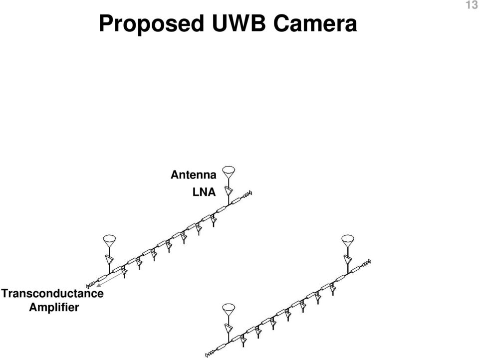
17 Proposed UWB Camera 13 Antenna LNA

18 Proposed UWB Camera 13 Antenna LNA

19 Proposed UWB Camera 13 Antenna LNA Transconductance Amplifier
20 Proposed UWB Camera 13 Antenna LNA Unit Delay Cell ( τ ) Transconductance Amplifier Delay Line Termination

21 Proposed UWB Camera 13 Antenna LNA Unit Delay Cell ( τ ) Transconductance Amplifier Detector Driver (RF Buffer) Delay Line Termination
22 Proposed UWB Camera 13 Antenna LNA Unit Delay Cell ( τ ) Transconductance Amplifier Detector Driver (RF Buffer) Detector Array (7X7 Pixels) Delay Line Termination
23 Proposed UWB Camera 13 Electromagnetic Beams (7X7 Directions) Antenna LNA Unit Delay Cell ( τ ) Transconductance Amplifier Detector Driver (RF Buffer) Detector Array (7X7 Pixels) Delay Line Termination
24 Signal Flow for Pixel X-direction Y-direction 4τ RF in11 Delay In 11 Out 44 = 4τ + 4τ = 8τ Delay In 12 Out 44 = 4τ + 4τ = 8τ Delay In 21 Out 44 = 4τ + 4τ = 8τ Delay In 22 Out 44 = 4τ + 4τ = 8τ 4τ Z RF in21 RF in12 X Y 4τ RF in22 4τ
25 Signal Flow for Pixel X-direction Y-direction 5τ RF in11 Delay In 11 Out 52 = 5τ + 2τ = 7τ Delay In 12 Out 52 = 5τ + 6τ = 11τ Delay In 21 Out 52 = 3τ + 2τ = 5τ Delay In 22 Out 52 = 3τ + 6τ = 9τ 3τ Z RF in21 RF in12 X Y 2τ 6τ RF in22
26 UWB Camera Block Diagram 16 RF in11 RF in12 LNA VGA Bias Circuit Transconductance Amplifier Detector Driver (RF Buffer) Energy Detector Digital Controller RF in21 RF in22
27 Embedded Equalizer 17 Original-Embedded Equalizer Optimal-Embedded Equalizer Array Gain Array Gain Array Gain Array Gain Group Delay Gain Frequency Frequency Group Delay Gain Frequency Frequency Group Delay Gain Frequency Frequency Group Delay Gain Frequency Frequency Embedded equalizer maintains the same array gain for all directions.
28 UWB Front-end Design 18 Vdd Mf Lsp Pad 50Ω M1 Ls M2 Delay Line Pad Lg Vb1 Vin+ Vin- UWB LNA Vb2 Vb3 Vb4 3-Stage UWB VGA -3dB bandwidth Power gain S11 (1GHz-15GHz) Noise figure 1 db Compression Point (input power) Current Consumption 17GHz 19dB <-10dB <4.5dB -19dBm@1GHz, -22dBm@15GHz
29 UWB Front-End Measurement Results S21 (db) NF (db) Frequency (GHz) Frequency (GHz) Group Delay (ps) Frequency (GHz) S11(dB) Frequency (GHz)
30 Amplifier and Driver Design 20 Vdd + _ Vout Lm Vdd Pad Vb5 Vb6 Transconductance Amplifier 30mS transconductance Gain with 1.5V Detector Driver (RF Buffer) 2dB Voltage Gain with 1.5V
31 Energy Detector Design 21 Input Output Squarer Lowpass filter Integrator 3-Bit ADC Vdd Vo1 Vc1 Vo2 + Vb8 Cp Vc2 Vo3 Vin _ Vc3 Vb7 Energy detector has low power and consumes small area.
32 Pulse Energy Detector Measurement Results Monocycle Pulser Monocycle Pulser 180 Hybrid Detector Driver Monocycle Pulser 180 Hybrid Detector Driver Squarer Squarer Integrator Integrator Digital Oscilloscope 50Ω Digital Oscilloscope 50Ω Digital Oscilloscope 50Ω 1nF Voltage (mv) Voltage (mv) Voltage (mv) Time (nsec) Time (nsec) Time (nsec) 22
33 23 Outline Introduction Multi-Beam Architectures for Antenna Array A CMOS UWB Camera UWB Camera Measurement Results Conclusion
34 Die Microphotograph 24 RFin11 RFin12 UWB Front-End Horizontal Delay Line Vertical Delay Line Unit Delay Cell RF Output Buffer UWB Gm Cell 4.1mm Pulse Energy Detector Digital Control Unit RFin21 4.1mm RFin22 Implemented in 0.13μm CMOS with 8 metal layers.
35 Single-Channel Measurements for Pixel Voltage (mv) RFin RFin11 RFin22 Time Domain Measurement Input Monocycle Time (psec) RFin12 Group Delay (psec) Power Gain (db) Frequency Domain Measurement Array Power Gain Frequency (GHz) Frequency (GHz)
36 Single-Channel Measurements for Pixel Voltage (mv) RFin RFin11 RFin22 Time Domain Measurement Input Monocycle Time (psec) RFin12 Group Delay (psec) Power Gain (db) Frequency Domain Measurement 30 Array Power Gain Frequency (GHz) Frequency (GHz)
37 Single-Channel Measurements for Pixel Voltage (mv) RFin RFin11 RFin22 Time Domain Measurement Input Monocycle Time (psec) RFin12 Group Delay (psec) Power Gain (db) Frequency Domain Measurement 30 Array Power Gain Frequency (GHz) Frequency (GHz)
38 Noise Figure and Linearity Measurements NF (db) Frequency (GHz) Pout (dbm) GHz 8GHz 15GHz Pin (dbm)
39 Synthesized Array Patterns 29 Pixel 41 Pixel 42 Pixel 43 Pixel 44 Pixel 51 Pixel 52 Pixel 53 z RF in11 RF in12 y y Pixel 61 Pixel 62 x x Pixel 71 RF in21 RF in22
40 Wireless Measurement Setup 30 Receiving Antenna Array HP 11966G Conical Log Spiral Antenna 3cm UWB Camera Chip 3cm Pulsed Sinusoid Generator Front Side Back Side Z. Low, et. al, AWPL 05 Reported UWB Camera measurements correspond to active receiving mode with 4cm antenna spacing.
41 Wireless Measurement Result 31 Theoretical Measured Maximum intensity is at the center pixel (pixel 44).
42 Wireless Measurement Result 32 Theoretical Measured Maximum intensity is at the bottom the left corner pixel (pixel 71).
43 Measurement Performance Summary 33 UWB Front-End (LNA + VGA) -3dB bandwidth 17GHz Power gain 19dB S11 (1GHz 15GHz) < -10dB Noise-Figure (1GHz 15GHz) < 4.5dB 1 db Compression Point (input power) -19dBm@1GHz, -22dBm@15GHz Power dissipation Complete 4-Channel 2D Multi-beam Array -3dB Bandwidth 15GHz Total array gain 24dB Noise-Figure (1GHz 14GHz) < 5.8dB (single channel worst case) 1 db Compression Point (input power) -24dBm@1GHz, -26dBm@15GHz UWB true time delay resolution 17.5ps UWB Camera spatial resolution 10 (antenna separation = 3cm) Total number of available beams 7X7=49 (Simultaneously) Power dissipation [email protected] Total number of on-chip spiral inductors 220 Technology 0.13µm CMOS Die Area 4.1mm x 4.1mm
44 Conclusions 34 Ultra wideband multi-beam arrays are strong candidates for high resolution radar and imaging applications. The proposed broadband multi-beam array architecture is introduced that is suitable for integrated circuits layout and reduces the chip area significantly. The first single-chip Ultra wideband Camera with 2X2 antennas and 7X7 simultaneous pixels is demonstrated in a 0.13μm CMOS technology.
45 Acknowledgement 35 This work was supported by Boeing Phantom Works, Seattle, WA National Science Foundation Our thanks to Fong Shi and Michael Foster, Boeing Phantom Works W-F. Yeh, S-W. Feng, Ray Chen, C.Y. Lee, and our group members, USC
US-SPI New generation of High performances Ultrasonic device
 US-SPI New generation of High performances Ultrasonic device Lecoeur Electronique - 19, Rue de Courtenay - 45220 CHUELLES - Tel. : +33 ( 0)2 38 94 28 30 - Fax : +33 (0)2 38 94 29 67 US-SPI Ultrasound device
CMOS 5GHz WLAN 802.11a/n/ac RFeIC WITH PA, LNA, AND SPDT
 CMOS 5GHz WLAN 802.11a/n/ac RFeIC WITH PA, LNA, AND SPDT Description RFX8055 is a highly integrated, single-chip, single-die RFeIC (RF Front-end Integrated Circuit) which incorporates key RF functionality
AMICSA 2012. Integrated SAR Receiver/Converter for L, C and X bands Markku Åberg VTT Technical Research Centre of Finland
 AMICSA 2012 Integrated SAR Receiver/Converter for L, C and X bands Markku Åberg VTT Technical Research Centre of Finland 2 The Team Markku Åberg (1), Jan Holmberg (1), Faizah Abu Bakar (2), Tero Nieminen
Spike-Based Sensing and Processing: What are spikes good for? John G. Harris Electrical and Computer Engineering Dept
 Spike-Based Sensing and Processing: What are spikes good for? John G. Harris Electrical and Computer Engineering Dept ONR NEURO-SILICON WORKSHOP, AUG 1-2, 2006 Take Home Messages Introduce integrate-and-fire
EVALUATION KIT AVAILABLE Single-Chip Global Positioning System Receiver Front-End BIAS CBIAS GND GND RFIN GND GND IFSEL
 19-3469; Rev 2; 4/08 EVALUATION KIT AVAILABLE Single-Chip Global Positioning System General Description The complete single-chip global positioning system (GPS) RF front-end utilizes many innovative and
US-Key New generation of High performances Ultrasonic device
 US-Key New generation of High performances Ultrasonic device US-Key connected to a laptop computer US-Key Ultrasound device single channel Features USB2 High Speed connection Ultralow noise preamplifier
Wireless Security Camera
 Wireless Security Camera Technical Manual 12/14/2001 Table of Contents Page 1.Overview 3 2. Camera Side 4 1.Camera 5 2. Motion Sensor 5 3. PIC 5 4. Transmitter 5 5. Power 6 3. Computer Side 7 1.Receiver
Ultra Wideband Signal Impact on IEEE802.11b Network Performance
 Ultra Wideband Signal Impact on IEEE802.11b Network Performance Matti Hämäläinen 1, Jani Saloranta 1, Juha-Pekka Mäkelä 1, Tero Patana 2, Ian Oppermann 1 1 Centre for Wireless Communications (CWC), University
Wideband Driver Amplifiers
 The driver amplifier is a wideband, 1 khz to 4 GHz amplifier intended for use in broadband microwave and high data rate systems. The is a 3-stage high output power modulator driver amplifier that can provide
MATRIX TECHNICAL NOTES
 200 WOOD AVENUE, MIDDLESEX, NJ 08846 PHONE (732) 469-9510 FAX (732) 469-0418 MATRIX TECHNICAL NOTES MTN-107 TEST SETUP FOR THE MEASUREMENT OF X-MOD, CTB, AND CSO USING A MEAN SQUARE CIRCUIT AS A DETECTOR
NBB-402. RoHS Compliant & Pb-Free Product. Typical Applications
 Typical Applications Narrow and Broadband Commercial and Military Radio Designs Linear and Saturated Amplifiers 0 RoHS Compliant & Pb-Free Product NBB-402 CASCADABLE BROADBAND GaAs MMIC AMPLIFIER DC TO
Chapter 6 PLL and Clock Generator
 Chapter 6 PLL and Clock Generator The DSP56300 core features a Phase Locked Loop (PLL) clock generator in its central processing module. The PLL allows the processor to operate at a high internal clock
6.976 High Speed Communication Circuits and Systems Lecture 1 Overview of Course
 6.976 High Speed Communication Circuits and Systems Lecture 1 Overview of Course Michael Perrott Massachusetts Institute of Technology Copyright 2003 by Michael H. Perrott Wireless Systems Direct conversion
DC to 30GHz Broadband MMIC Low-Power Amplifier
 DC to 30GHz Broadband MMIC Low-Power Amplifier Features Integrated LFX technology: Simplified low-cost assembly Drain bias inductor not required Broadband 45GHz performance: Good gain (10 ± 1.25dB) 14.5dBm
Application Note Noise Frequently Asked Questions
 : What is? is a random signal inherent in all physical components. It directly limits the detection and processing of all information. The common form of noise is white Gaussian due to the many random
Full-Band Capture Cable Digital Tuning
 White Paper Full-Band Capture Cable Digital Tuning Cable operators are demanding devices that support an increasing number of simultaneous channels, which translates to multiple cable tuners and demodulators
Projects. Objective To gain hands-on design and measurement experience with real-world applications. Contents
 Projects Contents 9-1 INTRODUCTION...................... 43 9-2 PROJECTS......................... 43 9-2.1 Alarm Radar Sensor................ 43 9-2.2 Microwave FM Communication Link....... 46 9-2.3 Optical
APPLICATIO S TYPICAL APPLICATIO. LTC5507 100kHz to 1GHz RF Power Detector FEATURES DESCRIPTIO
 00kHz to GHz RF Power Detector FEATRES Temperature Compensated Internal Schottky Diode RF Detector Wide Input Power Range: 34dBm to 4dBm ltra Wide Input Frequency Range: 00kHz to 000MHz Buffered Output
SMART ANTENNA BEAMFORMING NETWORK Sharul Kamal Abdul Rahim Peter Gardner
 Smart Antena Beamforming Network 23 3 SMART ANTENNA BEAMFORMING NETWORK Sharul Kamal Abdul Rahim Peter Gardner 3.1 INTRODUCTION Smart Antenna with RF beamforming capability can greatly improve the performance
Hardware Documentation. Data Sheet HAL 401. Linear Hall-Effect Sensor IC. Edition Dec. 8, 2008 DSH000018_002EN
 Hardware Documentation Data Sheet HAL 41 Linear Hall-Effect Sensor IC Edition Dec. 8, 28 DSH18_2EN HAL41 DATA SHEET Copyright, Warranty, and Limitation of Liability The information and data contained in
Case Study Competition 2013. Be an engineer of the future! Innovating cars using the latest instrumentation!
 Case Study Competition 2013 Be an engineer of the future! Innovating cars using the latest instrumentation! The scenario You are engineers working on a project team that is tasked with the development
Analog Devices Welcomes Hittite Microwave Corporation NO CONTENT ON THE ATTACHED DOCUMENT HAS CHANGED
 Analog Devices Welcomes Hittite Microwave Corporation NO CONTENT ON THE ATTACHED DOCUMENT HAS CHANGED www.analog.com www.hittite.com THIS PAGE INTENTIONALLY LEFT BLANK v2.71 HMC42ST8 / 42ST8E AMPLIFIER,.4-2.2
Equalization/Compensation of Transmission Media. Channel (copper or fiber)
") Equalization/Compensation of Transmission Media Channel (copper or fiber) 1 Optical Receiver Block Diagram O E TIA LA EQ CDR DMUX -18 dbm 10 µa 10 mv p-p 400 mv p-p 2 Copper Cable Model Copper Cable 4-foot
Equalization/Compensation of Transmission Media Channel (copper or fiber) 1 Optical Receiver Block Diagram O E TIA LA EQ CDR DMUX -18 dbm 10 µa 10 mv p-p 400 mv p-p 2 Copper Cable Model Copper Cable 4-foot
Features. Applications. Transmitter. Receiver. General Description MINIATURE MODULE. QM MODULATION OPTIMAL RANGE 1000m
 Features MINIATURE MODULE QM MODULATION OPTIMAL RANGE 1000m 433.05 434.79 ISM BAND 34 CHANNELS AVAILABLE SINGLE SUPPLY VOLTAGE Applications IN VEHICLE TELEMETRY SYSTEMS WIRELESS NETWORKING DOMESTIC AND
A Wideband mm-wave CMOS Receiver for Gb/s Communications Employing Interstage Coupled Resonators
 A Wideband mm-wave CMOS Receiver for Gb/s Communications Employing Interstage Coupled Resonators Federico Vecchi 1,2, Stefano Bozzola 3, Massimo Pozzoni 4, Davide Guermandi 5, Enrico Temporiti 4, Matteo
SPECIFICATION. MAT.03A Embedded Active GPS and Cellular Antenna Assembly and Reference Board
 SPECIFICATION Part Number: MAT.03A Product Name: Features: MAT.03A Embedded Active GPS and Cellular Antenna Assembly and Reference Board 2in1 Embedded Antenna Solution Two SMA(F) connectors for Output
Broadband covering primary wireless communications bands: Cellular, PCS, LTE, WiMAX
 Ultra Linear Low Noise Monolithic Amplifier 50Ω The Big Deal 0.05 to 4 GHz Ultra High IP3 Broadband High Dynamic Range without external Matching Components May be used as a replacement for RFMD SPF-5189Z
LTCC Short Range Radar Sensor for Automotive Applications at 24 GHz
 LTCC Short Range Radar Sensor for Automotive Applications at 24 GHz P. Uhlig, C. Günner, S. Holzwarth, J. Kassner, R. Kulke, A. Lauer, M. Rittweger IMST GmbH, D-47475 Kamp-Lintfort, Germany, www.ltcc.de
A 2.4GHz Cascode CMOS Low Noise Amplifier
 A 2.4GHz Cascode CMOS Low Noise Amplifier Gustavo Campos Martins Universidade Federal de Santa Catarina Florianopolis, Brazil [email protected] Fernando Rangel de Sousa Universidade Federal de Santa Catarina
EM Noise Mitigation in Circuit Boards and Cavities
 EM Noise Mitigation in Circuit Boards and Cavities Faculty (UMD): Omar M. Ramahi, Neil Goldsman and John Rodgers Visiting Professors (Finland): Fad Seydou Graduate Students (UMD): Xin Wu, Lin Li, Baharak
MASW-000823-12770T. HMIC TM PIN Diode SP2T 13 Watt Switch for TD-SCDMA Applications. Features. Functional Diagram (TOP VIEW)
") Features Exceptional Loss = 0.35 db Avg @ 2025 MHz, 20mA Exceptional Loss = 0.50 db Avg @ 2025 MHz, 20mA Higher - Isolation = 31dB Avg @ 2025 MHz, 20mA Higher RF C.W. Input Power =13 W C.W.(-Ant Port)
Features Exceptional Loss = 0.35 db Avg @ 2025 MHz, 20mA Exceptional Loss = 0.50 db Avg @ 2025 MHz, 20mA Higher - Isolation = 31dB Avg @ 2025 MHz, 20mA Higher RF C.W. Input Power =13 W C.W.(-Ant Port)
Department of Information Engineering University of Pisa. Automotive Radar. Maria S. Greco. 2012 IEEE Radar Conference, May 7-11, Atlanta
 Department of Information Engineering University of Pisa. Automotive Radar Maria S. Greco Automotive RADAR Why? Automotive RADARs as core sensor (range, speed) of driver assistance systems: long range
A 10,000 Frames/s 0.18 µm CMOS Digital Pixel Sensor with Pixel-Level Memory
 Presented at the 2001 International Solid State Circuits Conference February 5, 2001 A 10,000 Frames/s 0.1 µm CMOS Digital Pixel Sensor with Pixel-Level Memory Stuart Kleinfelder, SukHwan Lim, Xinqiao
Monolithic Amplifier PMA2-43LN+ Ultra Low Noise, High IP3. 50Ω 1.1 to 4.0 GHz. The Big Deal
 Ultra Low Noise, High IP3 Monolithic Amplifier 50Ω 1.1 to 4.0 GHz The Big Deal Ultra low noise figure, 0.46 db High gain, high IP3 Small size, 2 x 2 x 1mm 2mm x 2mm Product Overview Mini-Circuits is an
AN-691 APPLICATION NOTE One Technology Way P.O. Box 9106 Norwood, MA 02062-9106 Tel: 781/329-4700 Fax: 781/461-3113 www.analog.com
 APPLICATION NOTE One Technology Way P.O. Box 9106 Norwood, MA 02062-9106 Tel: 781/329-4700 Fax: 781/461-3113 www.analog.com Operation of RF Detector Products at Low Frequency by Matthew Pilotte INTRODUCTION
Michael Hiebel. Fundamentals of Vector Network Analysis
 Michael Hiebel Fundamentals of Vector Network Analysis TABIH OF CONTENTS Table of contents 1 Introduction 12 1.1 What is a network analyzer? 12 1.2 Wave quantities and S-parameters 13 1.3 Why vector network
CONFERENCE SESSIONS MATRIX - MONDAY
 CONFERENCE SESSIONS MATRIX - MONDAY 7 05 GaN Devices 11 Graphene & III-V Devices 8 04 OPENING SESSION 06 Millimetre-Wave Low Noise Amplifiers 12 Millimetre-Wave Transceiver 9 07 Millimetre-Wave and THz
Synthetic Sensing: Proximity / Distance Sensors
 Synthetic Sensing: Proximity / Distance Sensors MediaRobotics Lab, February 2010 Proximity detection is dependent on the object of interest. One size does not fit all For non-contact distance measurement,
RF Measurements Using a Modular Digitizer
 RF Measurements Using a Modular Digitizer Modern modular digitizers, like the Spectrum M4i series PCIe digitizers, offer greater bandwidth and higher resolution at any given bandwidth than ever before.
MANUAL FOR RX700 LR and NR
 MANUAL FOR RX700 LR and NR 2013, November 11 Revision/ updates Date, updates, and person Revision 1.2 03-12-2013, By Patrick M Affected pages, ETC ALL Content Revision/ updates... 1 Preface... 2 Technical
FM Radio Transmitter & Receiver Modules
 FM Radio Transmitter & Receiver Modules T5 / R5 Features MINIATURE SIL PACKAGE FULLY SHIELDED DATA RATES UP TO 128KBITS/S RANGE UPTO 300 METRES SINGLE SUPPLY VOLTAGE INDUSTRY PIN COMPATIBLE QFMT5-434 TEMP
IC-EMC Simulation of Electromagnetic Compatibility of Integrated Circuits
 IC-EMC Simulation of Electromagnetic Compatibility of Integrated Circuits SUMMARY CONTENTS 1. CONTEXT 2. TECHNOLOGY TRENDS 3. MOTIVATION 4. WHAT IS IC-EMC 5. SUPPORTED STANDARD 6. EXAMPLES CONTEXT - WHY
Broadband covering primary wireless communications bands: Cellular, PCS, LTE, WiMAX
 High Gain, High IP3 Monolithic Amplifier 50Ω 0.01 to 6 GHz The Big Deal High Gain Broadband High Dynamic Range without external Matching Components May be used as a replacement to RFMD SBB5089Z a,b SOT-89
HP 8970B Option 020. Service Manual Supplement
 HP 8970B Option 020 Service Manual Supplement Service Manual Supplement HP 8970B Option 020 HP Part no. 08970-90115 Edition 1 May 1998 UNIX is a registered trademark of AT&T in the USA and other countries.
ILX511. 2048-pixel CCD Linear Image Sensor (B/W)
") 248-pixel CCD Linear Image Sensor (B/W) Description The ILX is a rectangular reduction-type CCD linear image sensor designed for bar code POS hand scanner and optical measuring equipment use. A built-in
248-pixel CCD Linear Image Sensor (B/W) Description The ILX is a rectangular reduction-type CCD linear image sensor designed for bar code POS hand scanner and optical measuring equipment use. A built-in
Frequency Response of Filters
 School of Engineering Department of Electrical and Computer Engineering 332:224 Principles of Electrical Engineering II Laboratory Experiment 2 Frequency Response of Filters 1 Introduction Objectives To
Network Analyzer Operation
 Network Analyzer Operation 2004 ITTC Summer Lecture Series John Paden Purposes of a Network Analyzer Network analyzers are not about computer networks! Purposes of a Network Analyzer Measures S-parameters
Jeff Thomas Tom Holmes Terri Hightower. Learn RF Spectrum Analysis Basics
 Jeff Thomas Tom Holmes Terri Hightower Learn RF Spectrum Analysis Basics Learning Objectives Name the major measurement strengths of a swept-tuned spectrum analyzer Explain the importance of frequency
TowerJazz High Performance SiGe BiCMOS processes
 TowerJazz High Performance SiGe BiCMOS processes 2 Comprehensive Technology Portfolio 0.50 µm 0.35 µm 0.25 µm 0.18/0.16/0.152 µm 0.13 0.13µm BiCMOS, SiGe SiGe SiGe SiGe Power/BCD BCD BCD Power/BCD Image
High-Frequency Integrated Circuits
 High-Frequency Integrated Circuits SORIN VOINIGESCU University of Toronto CAMBRIDGE UNIVERSITY PRESS CONTENTS Preface, page xiii Introduction l 1.1 High-frequency circuits in wireless, fiber-optic, and
RF Power Amplifier PA10W Owner s Manual SpinCore Technologies, Inc. http://www.spincore.com
 RF Power Amplifier PA10W Owner s Manual SpinCore Technologies, Inc. http://www.spincore.com Congratulations and thank you for choosing a design from SpinCore Technologies, Inc. We appreciate your business!
INFRARED PARTS MANUAL
 INFRARED PARTS MANUAL PIR325 FL65 GLOLAB CORPORATION Thank you for buying our Pyroelectric Infrared components. The goal of Glolab is to produce top quality electronic kits, products and components. All
Wireless Communication and RF System Design Using MATLAB and Simulink Giorgia Zucchelli Technical Marketing RF & Mixed-Signal
 Wireless Communication and RF System Design Using MATLAB and Simulink Giorgia Zucchelli Technical Marketing RF & Mixed-Signal 2013 The MathWorks, Inc. 1 Outline of Today s Presentation Introduction to
8 Gbps CMOS interface for parallel fiber-optic interconnects
 8 Gbps CMOS interface for parallel fiberoptic interconnects Barton Sano, Bindu Madhavan and A. F. J. Levi Department of Electrical Engineering University of Southern California Los Angeles, California
76-77 GHz RF Transmitter Front-end for W-band Radar Applications
 Freescale Semiconductor Data Sheet Summary for MC33 7-77 GHz RF Transmitter Front-end for W-band Radar Applications The MR2001 is a scalable three package solution for automotive radar modules. The chipset
TS5010 TeraTune Programmable Bandpass Filter
 FEATURES 0MHz to 90MHz Tunability 240 Frequency Steps Constant Q, Two-pole Butterworth Bandpass 1W Power Handling 0µs Tuning Speed Serial/Parallel Modes -40C to +85C DESCRIPTION The TS5010 series of TeraTune
AN1200.04. Application Note: FCC Regulations for ISM Band Devices: 902-928 MHz. FCC Regulations for ISM Band Devices: 902-928 MHz
 AN1200.04 Application Note: FCC Regulations for ISM Band Devices: Copyright Semtech 2006 1 of 15 www.semtech.com 1 Table of Contents 1 Table of Contents...2 1.1 Index of Figures...2 1.2 Index of Tables...2
A Low Frequency Adapter for your Vector Network Analyzer (VNA)
") Jacques Audet, VE2AZX 7525 Madrid St, Brossard, QC, Canada J4Y G3: [email protected] A Low Frequency Adapter for your Vector Network Analyzer (VNA) This compact and versatile unit extends low frequency
Jacques Audet, VE2AZX 7525 Madrid St, Brossard, QC, Canada J4Y G3: [email protected] A Low Frequency Adapter for your Vector Network Analyzer (VNA) This compact and versatile unit extends low frequency
Nomadic Base Station (NBS): a Software Defined Radio (SDR) based Architecture for Capacity Enhancement in Mobile Communications Networks
: a Software Defined Radio (SDR) based Architecture for Capacity Enhancement in Mobile Communications Networks") International Journal of Engineering & Technology IJET-IJENS Vol: 11 No: 01 253 Nomadic Base Station (NBS): a Software Defined Radio (SDR) based Architecture for Capacity Enhancement in Mobile Communications
International Journal of Engineering & Technology IJET-IJENS Vol: 11 No: 01 253 Nomadic Base Station (NBS): a Software Defined Radio (SDR) based Architecture for Capacity Enhancement in Mobile Communications
Design and Test of Fast Laser Driver Circuits
 Design and Test of Fast Laser Driver Circuits Since the invention of the laser by Theodore H Maiman 50 years ago, lasers have found widespread applications in various technological fields, such as telecommunications,
Lecture 1: Communication Circuits
 EECS 142 Lecture 1: Communication Circuits Prof. Ali M. Niknejad University of California, Berkeley Copyright c 2005 by Ali M. Niknejad A. M. Niknejad University of California, Berkeley EECS 142 Lecture
Agilent AN 1315 Optimizing RF and Microwave Spectrum Analyzer Dynamic Range. Application Note
 Agilent AN 1315 Optimizing RF and Microwave Spectrum Analyzer Dynamic Range Application Note Table of Contents 3 3 3 4 4 4 5 6 7 7 7 7 9 10 10 11 11 12 12 13 13 14 15 1. Introduction What is dynamic range?
A Laser Scanner Chip Set for Accurate Perception Systems
 A Laser Scanner Chip Set for Accurate Perception Systems 313 A Laser Scanner Chip Set for Accurate Perception Systems S. Kurtti, J.-P. Jansson, J. Kostamovaara, University of Oulu Abstract This paper presents
RF FRONT END FOR HIGH BANDWIDTH BUNCH ARRIVAL TIME MONITORS IN FREE-ELECTRON LASERS AT DESY
 Proceedings of IBIC212, Tsukuba, Japan RF FRONT END FOR HIGH BANDWIDTH BUNCH ARRIVAL TIME MONITORS IN FREE-ELECTRON LASERS AT DESY A. Penirschke #, A. Angelovski, M. Hansli, R. Jakoby, Institut für Mikrowellentechnik
Silicon Seminar. Optolinks and Off Detector Electronics in ATLAS Pixel Detector
 Silicon Seminar Optolinks and Off Detector Electronics in ATLAS Pixel Detector Overview Requirements The architecture of the optical links for the ATLAS pixel detector ROD BOC Optoboard Requirements of
Product Information S N O. Portable VIP protection CCTV & Alarm System 2
 Product Information S N O Portable VIP protection CCTV & Alarm System 2 G O V E R N M E N T A L S E C U R I T Y S O L U T I VIP KIT Rapid Deployment VIP Protection Kit The VIP KIT has been designed to
DRTS 33. The new generation of advanced test equipments for Relays, Energy meters, Transducers and Power quality meters
 The new generation of advanced test equipments for Relays, Energy meters, Transducers and Power quality meters Testing all relay technologies: electromechanical, solid state, numerical and IEC61850 Manual
it4036f 120-ps Wideband Phase Delay Description Features Device Diagram Timing Diagram
 Description The it436f is an ultra-wideband phase delay with an ECL topology to ensure high-speed operation that accepts either single-ended or differential data input. Its high output voltage, excellent
DATA SHEET. SiGe LOW NOISE AMPLIFIER FOR GPS/MOBILE COMMUNICATIONS. Part Number Order Number Package Marking Supplying Form
 DESCRIPTION The μpc8tk is a silicon germanium (SiGe) monolithic integrated circuit designed as a low noise amplifier for GPS and mobile communications. The package is -pin lead-less minimold, suitable
Rayson. Bluetooth Module
 Rayson Class2 BC04-ext Module Features Bluetooth Module BTM-182 Outline Class2 module with printed pcb antenna Bluetooth standard Ver. 2.1 + EDR compliant. Low current consumption : Hold,Sniff,Park,Deep
Advantage of the CMOS Sensor
 - TECHNICAL DOCUMENTATION Advantage of the CMOS Sensor Contents 1. Introduction...2 2. Comparing CCD & CMOS...2 3. CMOS Sensor Exmor...3 4. New Wide-D Technology Using High-speed Readout of the CMOS Sensor
Agilent N8973A, N8974A, N8975A NFA Series Noise Figure Analyzers. Data Sheet
 Agilent N8973A, N8974A, N8975A NFA Series Noise Figure Analyzers Data Sheet Specifications Specifications are only valid for the stated operating frequency, and apply over 0 C to +55 C unless otherwise
LM 358 Op Amp. If you have small signals and need a more useful reading we could amplify it using the op amp, this is commonly used in sensors.
 LM 358 Op Amp S k i l l L e v e l : I n t e r m e d i a t e OVERVIEW The LM 358 is a duel single supply operational amplifier. As it is a single supply it eliminates the need for a duel power supply, thus
Sentinel-SSO: Full DDR-Bank Power and Signal Integrity. Design Automation Conference 2014
 Sentinel-SSO: Full DDR-Bank Power and Signal Integrity Design Automation Conference 2014 1 Requirements for I/O DDR SSO Analysis Modeling Package and board I/O circuit and layout PI + SI feedback Tool
Jeff Thomas Tom Holmes Terri Hightower. Learn RF Spectrum Analysis Basics
 Jeff Thomas Tom Holmes Terri Hightower Learn RF Spectrum Analysis Basics Agenda Overview: Spectrum analysis and its measurements Theory of Operation: Spectrum analyzer hardware Frequency Specifications
PCM Encoding and Decoding:
 PCM Encoding and Decoding: Aim: Introduction to PCM encoding and decoding. Introduction: PCM Encoding: The input to the PCM ENCODER module is an analog message. This must be constrained to a defined bandwidth
Understanding Network Video Security Systems
 Understanding Network Video Security Systems Chris Adesanya Panasonic System Solutions Company [email protected] Introduction and Overview This session will provide vendor neutral introduction
APPLICATION NOTE. Basler racer Migration Guide. Mechanics. www.baslerweb.com. Flexible Mount Concept. Housing
 62 62 APPLICATION NOTE www.baslerweb.com Basler racer Migration Guide This paper describes what to consider when replacing the Basler L100 Camera Link or the Basler runner Gigabit Ethernet (GigE) line
CMS Tracker module / hybrid tests and DAQ development for the HL-LHC
 CMS Tracker module / hybrid tests and DAQ development for the HL-LHC S. Mersi, G. Auzinger [email protected] 1 Outline Reminder: the Ph2 CMS Tracker upgrade pt Modules: principle, elements, electronics
Symbol Parameters Units Frequency Min. Typ. Max. 850 MHz 14.8 16.3 17.8
 Product Description Sirenza Microdevices SGC-689Z is a high performance SiGe HBT MMIC amplifier utilizing a Darlington configuration with a patented active-bias network. The active bias network provides
The Effective Number of Bits (ENOB) of my R&S Digital Oscilloscope Technical Paper
 of my R&S Digital Oscilloscope Technical Paper") The Effective Number of Bits (ENOB) of my R&S Digital Oscilloscope Technical Paper Products: R&S RTO1012 R&S RTO1014 R&S RTO1022 R&S RTO1024 This technical paper provides an introduction to the signal
The Effective Number of Bits (ENOB) of my R&S Digital Oscilloscope Technical Paper Products: R&S RTO1012 R&S RTO1014 R&S RTO1022 R&S RTO1024 This technical paper provides an introduction to the signal
DWH-1B. with a security system that keeps you in touch with what matters most
 expand your senses comfort zone with a security system that keeps you in touch with what matters most HOME & SMALL BUSINESS DWH-1B designed with innovated technologies for indoor/outdoor convenient placement
Application Note SAW-Components
 Application Note SAW-Components Principles of SAWR-stabilized oscillators and transmitters. App: Note #1 This application note describes the physical principle of SAW-stabilized oscillator. Oscillator
DRM compatible RF Tuner Unit DRT1
 FEATURES DRM compatible RF Tuner Unit DRT1 High- Performance RF Tuner Frequency Range: 10 KHz to 30 MHz Input ICP3: +13,5dBm, typ. Noise Figure @ full gain: 14dB, typ. Receiver Factor: -0,5dB, typ. Input
Scan Time Reduction and X-ray Scatter Rejection in Dual Modality Breast Tomosynthesis. Tushita Patel 4/2/13
 Scan Time Reduction and X-ray Scatter Rejection in Dual Modality Breast Tomosynthesis Tushita Patel 4/2/13 Breast Cancer Statistics Second most common cancer after skin cancer Second leading cause of cancer
RF Communication System. EE 172 Systems Group Presentation
 RF Communication System EE 172 Systems Group Presentation RF System Outline Transmitter Components Receiver Components Noise Figure Link Budget Test Equipment System Success Design Remedy Transmitter Components
Analog Signal Conditioning
 Analog Signal Conditioning Analog and Digital Electronics Electronics Digital Electronics Analog Electronics 2 Analog Electronics Analog Electronics Operational Amplifiers Transistors TRIAC 741 LF351 TL084
Extended Resolution TOA Measurement in an IFM Receiver
 Extended Resolution TOA Measurement in an IFM Receiver Time of arrival (TOA) measurements define precisely when an RF signal is received, necessary in the identification of type and mode of RF and radar
How To Use A Sound Card With A Subsonic Sound Card
 !"## $#!%!"# &"#' ( "#' )*! #+ #,# "##!$ -+./0 1" 1! 2"# # -&1!"#" (2345-&1 #$6.7 -&89$## ' 6! #* #!"#" +" 1##6$ "#+# #-& :1# # $ #$#;1)+#1#+
Optical Fibres. Introduction. Safety precautions. For your safety. For the safety of the apparatus
 Please do not remove this manual from from the lab. It is available at www.cm.ph.bham.ac.uk/y2lab Optics Introduction Optical fibres are widely used for transmitting data at high speeds. In this experiment,
SPADIC: CBM TRD Readout ASIC
 SPADIC: CBM TRD Readout ASIC Tim Armbruster [email protected] HIC for FAIR, Darmstadt Schaltungstechnik Schaltungstechnik und und February 2011 Visit http://spadic.uni-hd.de 1. Introduction
Power Amplifier Gain Compression Measurements
 Technical Brief Power Amplifier Gain Compression Measurements GPIB Private Bus Sweep Out Sweep In Pulse In AC Mod Out Blank/Marker Out Blanking In Overview The 1 db gain compression of an amplifier describes
RFSPACE CLOUD-IQ #CONNECTED SOFTWARE DEFINED RADIO
 CLOUD-IQ #CONNECTED SOFTWARE DEFINED RADIO 1 - SPECIFICATIONS Cloud-IQ INTRODUCTION The Cloud-IQ is a high performance, direct sampling software radio with an ethernet interface. It offers outstanding
Demonstration of a Software Defined Radio Platform for dynamic spectrum allocation.
 Demonstration of a Software Defined Radio Platform for dynamic spectrum allocation. Livia Ruiz Centre for Telecommunications Value-Chain Research Institute of Microelectronic and Wireless Systems, NUI
SZI 1029. IR Audio Transmission Technology Modulators/Radiators
 General Description The is a 5-W high-power radiator for use with all wideband and narrowband modulators. The radiator is automatically switched on by the RF carrier and can cover areas of up to 800 m
CONDUCTED EMISSION MEASUREMENT OF A CELL PHONE PROCESSOR MODULE
 Progress In Electromagnetics esearch C, Vol. 42, 191 203, 2013 CONDUCTED EMISSION MEASUEMENT OF A CELL PHONE POCESSO MODULE Fayu Wan *, Junxiang Ge, and Mengxiang Qu Nanjing University of Information Science
GaN High Power Amplifiers: Optimal Solutions Addressing Pico to Macro BTS Demands
 GaN High Power Amplifiers: Optimal Solutions Addressing Pico to Macro BTS Demands David Runton; Engineering Director, PBBU David Aichele; Marketing Director, PBBU IWPC Atlanta 2012 IWPC Chicago 2010 1
MAS.836 HOW TO BIAS AN OP-AMP
 MAS.836 HOW TO BIAS AN OP-AMP Op-Amp Circuits: Bias, in an electronic circuit, describes the steady state operating characteristics with no signal being applied. In an op-amp circuit, the operating characteristic
'Possibilities and Limitations in Software Defined Radio Design.
 'Possibilities and Limitations in Software Defined Radio Design. or Die Eierlegende Wollmilchsau Peter E. Chadwick Chairman, ETSI ERM_TG30, co-ordinated by ETSI ERM_RM Software Defined Radio or the answer
ZLPLL Local Oscillator
 ZLPLL Local Oscillator Wayne Knowles, ZL2BKC [email protected] Contents 1 Introduction... 3 2 Specifications... 3 3 Performance... 4 3.1 Phase Noise... 4 3.2 Output Level... 4 3.3 Harmonic Level...