How To Build A Reinforced Concrete Floor Plan
|
|
|
- Cecilia Richards
- 5 years ago
- Views:
Transcription
1 DIFFERENT FLOOR SYSTEMS USED IN STRUCTURES. Beams and girders are often used to support building floors.in particular, a girder is the main load-carrying element of the floor, whereas the smaller element having a shorter span connected to the girders are called beams. Often the loads that are applied to a beam or girder are transmitted to it by the floor that is supported by the beam or girder. Again, it is important to be able to appropriately idealize the system a series of models, whish can be used to determine, to a close approximation, the forces acting in the member. Consider, for example, the framing used to support a typical floor slab in a building.the slab is support by floor joists located at even intervals.

2 Floor Systems Basically, a building is a series of floors held up by columns and walls. There are a number of standard floor/roof structural systems used in cast-in-place reinforced concrete construction.

3 Project No.10 DIFFERENT FLOOR SYSTEMS USED IN STRUCTURES.

4 Two-way flat plate system. There are no beams between the columns. Instead, the floor is slightly thicker and more heavily reinforced in both directions. There is extra reinforcing in the floor at the columns to transfer the loads properly. Two-way flat slab with drop panels. The extra thickness around the columns is there to strengthen the column-floor connection and resist the negative moments. The floor itself can be slightly thinner with less dead weight. One-way beam and slab. The floor loads are transferred to the beams, which are then transferred to the columns. One-way joist slab. The joists act like small beams. This floor system is very economical because the formwork is readily available, and less reinforcing is need. Because there's only a small span between each joist, the slab can be thinner. One-way wide module joist slab. in the lower middle is a variation on the one-way joist slab. Two-way joist slab, also called a waffle slab. Because there are joists in both directions, this floor system is the strongest and will have the least deflection. It's typically used when stiffness is important or if there are abnormally heavy loads

5 Image-GoddenF76 Typical oneway beam grid and slab system. This parking structure has columns on a rectangular grid pattern. The essentially one-way design of the system can be seen by the relative lengths and sections of the main beam, and the primary and secondary beams under the slab. The rectangular shape of the unsupported slab also indicates one-way slab action. Image-GoddenF77 Typical waffleslab for parking structure. With columns on a 33-ft x 27-ft pattern, the design uses 3-ft square waffles. Note the infilling of the squares at the head of the column to resist both shear and negative moments.

6 Image-GoddenF78 Waffle-slab roof, San Diego Airport. Not heavily loaded as a roof structure, the waffle slab system could be extended into the overhang where the moments are negative. Note also the supporting columns with a built-in point of zero moment at two-thirds height. (San Diego, California) Image-GoddenF79 Typical flat slab construction for a parking structure. Note the square column capitals that increase the area of the slab resisting punching shear at the columns.
 Image-GoddenF79 Typical flat slab construction for a parking structure.")
7 Image-GoddenF80 Typical flat plate construction. This office building under construction uses flat plates for the floors and constant section columns without capitals. The shear stiffness of the building is provided by elevator shafts and stair wells. Due to the relatively small floor loading and the close column spacing, flat plate construction was possible. For heavier loading and larger column spacing, column capitals are required (GoddenF73), and for even larger spans to reduce the self-weight, waffle slabs are used (GoddenF77)

8 STRUCTURAL ONE-WAY/TWO-WAY CONCRETE SLAB DESIGN (IBM & compatibles): OT designs one-way and two-way concrete slabs under applied loads using the design procedures of Winter and Nilson, the ACI Direct Design Method and ACI moment coefficients. * OT computes the minimum slab thickness required by codes, flexural steel bar sizes, and design moments. -Data inputs for two way slabs are the short and long span lengths, minimum desired thickness live and dead loads, reinforcing steel yield strength, concrete density, and compressive strength. Two-way slab design also requires the column dimensions and interior and exterior beam dimensions.

9 OT calculates corner position, central, longside exposed, and shortside exposed positions. Outputs are design moments, minimum required thickness actual and allowable shear stress, and the number and size of reinforcing bars for the two half-column strips and the middle strip, for the short and the long spans. Detailed inputs and outputs may be printed. The user must note that certain limiting assumptions apply to the direct design method such as the ratio of short to long side length, maximum column offset, live to dead load. etc. The program is fully prompted and interactive. Runs in English or SI Metric units.

10 One way slab One way slabs are designed to transfer their loads to only two opposite support walls. Generally for spans up to 3.60 meters and with length/breadth ratio is greater than 0.60 one way slabs.can be provided Back to One Way Designer :Effective Span This is the distance between center of two opposite supports. In the case of one way slab the pair of opposite supports with shortest distance between them are taken as the supports. (Span.(is specified in meters Back to One Way Designer :Live Load This is the load expected to come on the slab after construction excluding the self weight of the slab. This will include load of flooring material provided and any other load that will come on the slab when using it. Generally a live load of 200 to 250 Kg/m² is recommended for residential buildings and more.for commercial buildings Back to One Way Designer

11 Two way slab Two way slabs are designed to transfer their loads to all the four support walls. Generally for spans greater than 3.60 meters and with length/breadth ratio is less than 0.60 two way slabs can be provided. In this case main bars (referred under Part 1) are provided in both.directions, mutually at right angles Back to Two Way Designer: Short Span This is the distance between center of two opposite supports. In the case of Two way slab the distance between the pair of opposite supports with shorter distance between them are taken as the Short.(span. (Span is specified in meters Back to Two Way Designer :Long Span This is the distance between center of two opposite supports. In the case of Two way slab the distance between the pair of opposite supports with larger distance between them are taken as the long.(span. (Span is specified in meters Definition of all other terms are same as that given for part 1 above. Please note that in two way slab, separate distribution bars.are not provided Back to Two Way Designer Technical aspects

12 The design tried here, is based on the "Basic Elastic Theory". Two way slab design is based on the Rankine-Grashoff Theory. Reinforced cement concrete using 20 mm nominal size granite broken stones -M150 (1:2:4) is assumed for design. MS bars with a tensile strength of 4200 Kg/cm² is proposed for reinforcement. The factor of safety assumed is 3 In both types bend up the main bars at distance of 1/7th of span from supports to take negative bending

13 Slabs - Introduction Reinforced concrete slabs are a common building system because they can be built economically with essentially any plan geometry and supported by randomly located beams, columns and walls. Slabs must have sufficient strength to carry loads safely but must not deflect or crack excessively. It is these two serviceability factors that provide the criteria on which the success of a slab design is ultimately judged and their importance cannot.be overly emphasized

14 In theory, because they are highly statically indeterminate structures, the analysis of reinforced concrete slabs is complex. Fortunately, for most slabs, a satisfactory design can be obtained by uncoupling the strength and serviceability requirements leading to relatively simple design procedures. Since slab sections are usually lightly reinforced, they can maintain an essentially constant moment capacity after yielding of the reinforcement for large changes in curvature thereby permitting considerable redistribution of moments within the slab. This leads to simpler moment fields and patterns of reinforcement. Deflection requirements are met by.selecting appropriate slab thickness

15 The above steps are not independent and indeed may not be completed in the order listed. For example, it is usual to make at least a preliminary evaluation of Shear. capacity when selecting slab thickness There are a number of calculations in the design of slab systems that are tedious when performed manually even with the use of electronic calculators. Design aids in the form of charts or tables are provided to facilitate many of these calculations. Design examples are presented to assist in interpreting the provisions of specific clauses of the Standard and to illustrate the use of the design aids. As a result, each example is an incomplete design in that only portions of the.slab system are considered

16 The structural behaviour of reinforced concrete slab structures depends primarily on how they are supported. Slabs supported so that they tend to deform into a cylindrical surface carry load essentially in one direction only and are referred to as one-way slabs. Such slabs may be designed as beam strips in the direction of curvature. Slabs supported on regularly spaced columns, or walls, forming approximately square panels deform to carry load in two orthogonal directions. Such slabs are referred to as regular two-way slabs (see Clause 13.1) and may be designed for uniformly distributed gravity loads using the simplification of perpendicular design strips. Slabs supported on randomly spaced columns and/or with randomly placed beams, walls or openings are referred to as irregular slabs. With irregular slabs, the loads in different regions will be carried by combinations of either one-way or two-way action and considerable judgment is needed by the designer to ensure.both strength and serviceability requirements are met

17 Housing with Information - (Floors) Floors: Concrete is a natural choice for floors in homes ICF or concrete block walls. In addition to delivering benefits similar to the walls - resistance to natural forces (wind, rot and insects), sound reduction, and improved thermal performance - concrete floors are long-spanning, squeakless and can accommodate efficient, comfortable radiant heat systems. Floors fall into four categories: composite/steel joist concrete/steel deck concrete joists precast Composite Concrete/Steel Joists Light steel joists supporting concrete on a steel deck or ribbed steel pan are widely available. Typical spans =4.5 to 9.0 m or longer using mm joists plus mm concrete. "Hambro" a proprietary system, uses sheets of plywood temporarily held between joists with removable roll bars. Steel mesh is draped over the joist, then topped with concrete, bonding it to the top chord and creating a reinforced composite deck. The plywood and roll bars can be reused. Because of the composite action between joists and concrete, this system is somewhat lighter than plain joists/steel deck combinations.

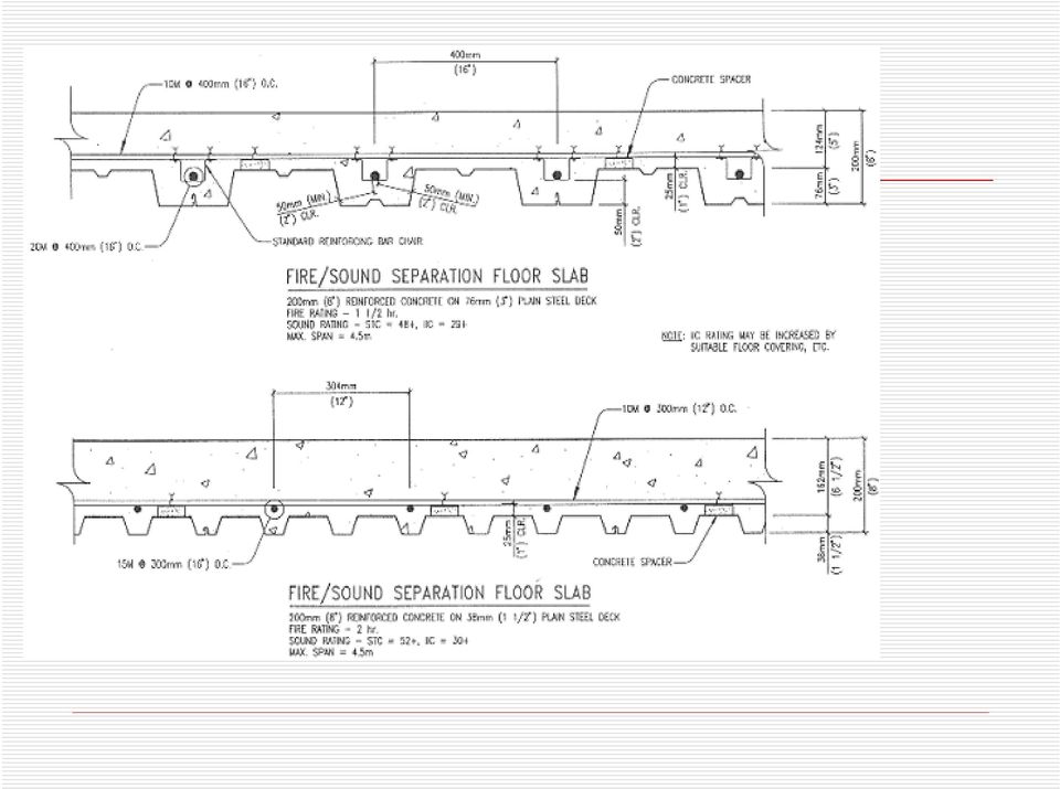
18 C-Floor is another unique composite system which uses cold formed C- sections at 600 to 750 mm o.c. instead of steel joists. The 200 to 250 mm deep C-sections support a 75 mm concrete slab on ribbed steel pan. Composite action is created by continuous bond bars secured to the top of the C-sections by patented shear transfer devices. Typical spans 5.5m to 7.9m support live loads up to 4.8 KPa. Concrete/Steel Deck Metal deck made from plain or galvanized steel sheet rolled into ribbed profiles can be used to form concrete floor slabs. Steel deck can be used strictly as a form for the concrete deck slab or it can be used as part of a composite design where deck and concrete act together structurally. For house construction, ga. ( mm) sheets with mm deep ribs is used. When the decking is used solely as a form, steel reinforcing rods and concrete are designed to carry all loads. Two examples that have been tested for fire and sound performance are shown below: Temporary supports installed under the deck at 1.5m before the pour must remain in place until the concrete reaches 80 percent of its design strength.

19 For a composite concrete/steel deck floor, a similar steel deck with "dimples" formed into the vertical flutes to create a physical bond with the concrete is used. This results in very efficient use of both materials. A 22 ga (0.75 mm) 75 mm composite deck with 75mm of 25 MPa concrete on top - total thickness 150 mm - can span up to 4.5m with no reinforcement. Temporary supports at 2.25m are required until the concrete develops sufficient strength. For design, either the ASCE Standard Specification for Design of Composite Slabs or the SDI Composite Deck Design Handbook should be followed. In Canada CSSBI S3-88 Criteria for the Design of Composite Slabs prepared by the Canadian Sheet Steel Building Institute or the Cement Association of Canada Concrete Housing Handbook could be used.

20
21 Concrete Joist. There are several systems available for casting concrete joist floors. Some use removable metal or fiberglass forms. Others use stay in place composite steel or plastic forms. Typical systems produce 200 mm deep ribs mm on centre. With mm thick topping, total floor thickness is mm. One reinforcing bar is placed near the bottom of each rib and most systems require welded wire mesh in the top slab. For joist floors using composite steel forms, spans of m are common. Bulkheads to retain the concrete between the ribs where they meet a wall are provided as part of the forming system. Composite steel forms that stay in place are available from Canadian Steel Inc. A method of forming concrete joist floors using foam forms is now making its way to North America from Europe where it has been used for several years. Hollow core foam planks, shaped to form concrete ribs at mm centres, stay in place after temporary bracing is removed. Attachments for ceiling finishes can be incorporated into the foam floor forms.
22 Precast Precast prestressed hollow core concrete slabs or planks for housing are usually 1220 mm wide and 150 mm or 200 mm thick. Although designs and widths vary somewhat, they normally have evenly spaced voids running the length of the slab with prestressing tendons in between. Hollow core is machine-extruded in long continuous beds and cut into planks to final dimensions at the plant. They may be cut to customized widths or shapes and reinforced for stair openings and other speciality applications. Holes for services may be cut on site if necessary. Hollow core slabs are set on ICF walls by crane and anchored with bent reinforcing bars set into the shear key joint between planks. The joints are then grouted to complete the installation. Precast products have constant depth with a relatively flat top surface and a very smooth underside that can be exposed as a ceiling with a minimum of additional treatment. Carpet and underpad can be laid on top with a minimum of finishing and levelling. A thin cement/latex grout or a concrete topping is required under linoleum or other thin floor finishes. A 38mm concrete topping is applied where radiant heat is to be installed. Systems that employ small concrete T joists with light autoclaved cellular panels set between them to support a cast-in-place floor slab have been used for many years in other parts of the world. As the use of concrete in low rise housing in North America intensifies, this and other concrete floor systems will likely find their way into the marketplace.
23 Taken by your own digital camera
24 Taken by your own digital camera
25 Work Group:- Al-Rshodi. Abdullah Al-Ghmmas. abdalelah _ AbdulAziz Al-Ateeg.
DESIGN OF SLABS. Department of Structures and Materials Engineering Faculty of Civil and Environmental Engineering University Tun Hussein Onn Malaysia
 DESIGN OF SLABS Department of Structures and Materials Engineering Faculty of Civil and Environmental Engineering University Tun Hussein Onn Malaysia Introduction Types of Slab Slabs are plate elements
Technical Assignment 2 TABLE OF CONTENTS
 2 TABLE OF CONTENTS Executive Summary...3 Introduction..5 Gravity Loads......6 Design Codes......7 Materials..8 Existing Structural System.. 10 Existing Floor System 15 Alternate Floor Framing Systems...17
SLAB DESIGN. Introduction ACI318 Code provides two design procedures for slab systems:
 Reading Assignment SLAB DESIGN Chapter 9 of Text and, Chapter 13 of ACI318-02 Introduction ACI318 Code provides two design procedures for slab systems: 13.6.1 Direct Design Method (DDM) For slab systems
9.3 Two-way Slabs (Part I)
") 9.3 Two-way Slabs (Part I) This section covers the following topics. Introduction Analysis and Design Features in Modeling and Analysis Distribution of Moments to Strips 9.3.1 Introduction The slabs are
9.3 Two-way Slabs (Part I) This section covers the following topics. Introduction Analysis and Design Features in Modeling and Analysis Distribution of Moments to Strips 9.3.1 Introduction The slabs are
The following sketches show the plans of the two cases of one-way slabs. The spanning direction in each case is shown by the double headed arrow.
 9.2 One-way Slabs This section covers the following topics. Introduction Analysis and Design 9.2.1 Introduction Slabs are an important structural component where prestressing is applied. With increase
FUTURE SLAB. PENETRATIONS and. DEMOLITION of POST-TENSIONED FLOORS
 FUTURE SLAB PENETRATIONS and DEMOLITION of POST-TENSIONED FLOORS 1.0 INTRODUCTION Post-tensioned floor slabs in Australia and South East Asia are now universally regarded as the most cost effective form
Formwork for Concrete
 UNIVERSITY OF WASHINGTON DEPARTMENT OF CONSTRUCTION MANAGEMENT CM 420 TEMPORARY STRUCTURES Winter Quarter 2007 Professor Kamran M. Nemati Formwork for Concrete Horizontal Formwork Design and Formwork Design
Technical Notes 3B - Brick Masonry Section Properties May 1993
 Technical Notes 3B - Brick Masonry Section Properties May 1993 Abstract: This Technical Notes is a design aid for the Building Code Requirements for Masonry Structures (ACI 530/ASCE 5/TMS 402-92) and Specifications
DESIGN OF SLABS. 3) Based on support or boundary condition: Simply supported, Cantilever slab,
 Based on support or boundary condition: Simply supported, Cantilever slab,") DESIGN OF SLABS Dr. G. P. Chandradhara Professor of Civil Engineering S. J. College of Engineering Mysore 1. GENERAL A slab is a flat two dimensional planar structural element having thickness small compared
DESIGN OF SLABS Dr. G. P. Chandradhara Professor of Civil Engineering S. J. College of Engineering Mysore 1. GENERAL A slab is a flat two dimensional planar structural element having thickness small compared
SECTION 5 ANALYSIS OF CONTINUOUS SPANS DEVELOPED BY THE PTI EDC-130 EDUCATION COMMITTEE LEAD AUTHOR: BRYAN ALLRED
 SECTION 5 ANALYSIS OF CONTINUOUS SPANS DEVELOPED BY THE PTI EDC-130 EDUCATION COMMITTEE LEAD AUTHOR: BRYAN ALLRED NOTE: MOMENT DIAGRAM CONVENTION In PT design, it is preferable to draw moment diagrams
TABLE OF CONTENTS. Roof Decks 172 B, BA, BV Deck N, NA Deck. Form Decks 174.6 FD,.6 FDV Deck 1.0 FD, 1.0 FDV Deck 1.5 FD Deck 2.0 FD Deck 3.
 Pages identified with the NMBS Logo as shown above, have been produced by NMBS to assist specifiers and consumers in the application of New Millennium Building Systems Deck products. Pages identified with
Draft Table of Contents. Building Code Requirements for Structural Concrete and Commentary ACI 318-14
 Draft Table of Contents Building Code Requirements for Structural Concrete and Commentary ACI 318-14 BUILDING CODE REQUIREMENTS FOR STRUCTURAL CONCRETE (ACI 318 14) Chapter 1 General 1.1 Scope of ACI 318
4B-2. 2. The stiffness of the floor and roof diaphragms. 3. The relative flexural and shear stiffness of the shear walls and of connections.
 Shear Walls Buildings that use shear walls as the lateral force-resisting system can be designed to provide a safe, serviceable, and economical solution for wind and earthquake resistance. Shear walls
NCMA TEK CONCRETE MASONRY FOUNDATION WALL DETAILS. TEK 5-3A Details (2003)
") NCMA TEK National Concrete Masonry Association an information series from the national authority on concrete masonry technology CONCRETE MASONRY FOUNDATION WALL DETAILS TEK 5-3A Details (2003) Keywords:
NCMA TEK National Concrete Masonry Association an information series from the national authority on concrete masonry technology CONCRETE MASONRY FOUNDATION WALL DETAILS TEK 5-3A Details (2003) Keywords:
Design of reinforced concrete columns. Type of columns. Failure of reinforced concrete columns. Short column. Long column
 Design of reinforced concrete columns Type of columns Failure of reinforced concrete columns Short column Column fails in concrete crushed and bursting. Outward pressure break horizontal ties and bend
TECHNICAL SPECIFICATION SERIES 8000 PRECAST CONCRETE
 TECHNICAL SPECIFICATION SERIES 8000 PRECAST CONCRETE TECHNICAL SPECIFICATION PART 8000 - PRECAST CONCRETE TABLE OF CONTENTS Item Number Page 8100 PRECAST CONCRETE CONSTRUCTION - GENERAL 8-3 8101 General
POST AND FRAME STRUCTURES (Pole Barns)
") POST AND FRAME STRUCTURES (Pole Barns) Post and frame structures. The following requirements serve as minimum standards for post and frame structures within all of the following structural limitations:
POST AND FRAME STRUCTURES (Pole Barns) Post and frame structures. The following requirements serve as minimum standards for post and frame structures within all of the following structural limitations:
Detailing of Reinforcment in Concrete Structures
 Chapter 8 Detailing of Reinforcment in Concrete Structures 8.1 Scope Provisions of Sec. 8.1 and 8.2 of Chapter 8 shall apply for detailing of reinforcement in reinforced concrete members, in general. For
How To Design A Post Tensioned Deck For A Building
 SAMUEL ÁVILA STRUCTURAL OPTION FACULTY CONSULTANT: THOMAS BOOTHBY UNIVERSITY OF CENTRAL FLORIDA S ACADEMIC VILLAGES ORLANDO, FL THESIS PROPOSAL EXECUTIVE SUMMARY DECEMBER 12, 2005 Introduction: The University
Safe & Sound Bridge Terminology
 Safe & Sound Bridge Terminology Abutment A retaining wall supporting the ends of a bridge, and, in general, retaining or supporting the approach embankment. Approach The part of the bridge that carries
Design of Steel Structures Prof. S.R.Satish Kumar and Prof. A.R.Santha Kumar. Fig. 7.21 some of the trusses that are used in steel bridges
 7.7 Truss bridges Fig. 7.21 some of the trusses that are used in steel bridges Truss Girders, lattice girders or open web girders are efficient and economical structural systems, since the members experience
Building Construction. Structural Systems 1. Load-bearing wall construction 2. Skeleton framing 3. Combination of the two
 Structural Systems 1. Load-bearing wall construction 2. Skeleton framing 3. Combination of the two Factors governing type selection Economics not necessarily the one that requires the least structural
CONCRETE FLOOR SLAB & CASTING BED CONSTRUCTION
 CONCRETE FLOOR SLAB & CASTING BED CONSTRUCTION General 7 www.meadowburke.com 877-518-7665 MB1109 CONCRETE FLOOR SLAB AND CASTING BED CONSTRUCTION Quality Construction Begins at Ground Level Everything
SEISMIC DESIGN. Various building codes consider the following categories for the analysis and design for earthquake loading:
 SEISMIC DESIGN Various building codes consider the following categories for the analysis and design for earthquake loading: 1. Seismic Performance Category (SPC), varies from A to E, depending on how the
Page & Turnbull imagining change in historic environments through design, research, and technology
 DCI+SDE STRUCTURAL EVALUATIONS OFFICE BUILDING, TOOL SHED & WATER TANK, AND BLACKSMITH & MACHINE SHOP BUILDINGS SAN FRANCISCO, CALIFORNIA [14290] PRIMARY PROJECT CONTACT: H. Ruth Todd, FAIA, AICP, LEED
Section 5A: Guide to Designing with AAC
 Section 5A: Guide to Designing with AAC 5A.1 Introduction... 3 5A.3 Hebel Reinforced AAC Panels... 4 5A.4 Hebel AAC Panel Design Properties... 6 5A.5 Hebel AAC Floor and Roof Panel Spans... 6 5A.6 Deflection...
Fire and Concrete Structures
 Fire and Concrete Structures Authors: David N. Bilow, P.E., S.E., Director, Engineered Structures, Portland Cement Association 5420 Old Orchard Road, Skokie, IL 60077,Phone 847-972-9064, email: [email protected]
STRUCTURAL CONCEPT FOR LIGHT GAUGE STEEL FRAME SYSTEM
 Chapter 9 STRUCTURAL CONCEPT FOR LIGHT GAUGE STEEL FRAME SYSTEM 9.1 BACKGROUND Steel is widely used in the construction of multi-storey buildings. However, steel construction is seldom used and is traditionally
CH. 2 LOADS ON BUILDINGS
 CH. 2 LOADS ON BUILDINGS GRAVITY LOADS Dead loads Vertical loads due to weight of building and any permanent equipment Dead loads of structural elements cannot be readily determined b/c weight depends
INTRODUCTION TO BEAMS
 CHAPTER Structural Steel Design LRFD Method INTRODUCTION TO BEAMS Third Edition A. J. Clark School of Engineering Department of Civil and Environmental Engineering Part II Structural Steel Design and Analysis
Chapter 5 Bridge Deck Slabs. Bridge Engineering 1
 Chapter 5 Bridge Deck Slabs Bridge Engineering 1 Basic types of bridge decks In-situ reinforced concrete deck- (most common type) Pre-cast concrete deck (minimize the use of local labor) Open steel grid
Structural Failures Cost Lives and Time
 Structural Failures Cost Lives and Time Recent failures of storage bins, silos and other structures highlight the need to increase awareness of hazards associated with these structures. Since 2010, one
MECHANICS OF SOLIDS - BEAMS TUTORIAL 1 STRESSES IN BEAMS DUE TO BENDING. On completion of this tutorial you should be able to do the following.
 MECHANICS OF SOLIDS - BEAMS TUTOIAL 1 STESSES IN BEAMS DUE TO BENDING This is the first tutorial on bending of beams designed for anyone wishing to study it at a fairly advanced level. You should judge
COMMONLY USED RESIDENTIAL BUILDING CODES
 COMMONLY USED RESIDENTIAL BUILDING CODES INTERNATIONAL RESIDENTIAL CODE (2009) form revised 5/10 FOUNDATION 1. DESIGN OF FORMWORK. Section 1906.1 IBC 2009, Section R404.1.2.3.6 IRC 2009, ACI 318 Section
16. Beam-and-Slab Design
 ENDP311 Structural Concrete Design 16. Beam-and-Slab Design Beam-and-Slab System How does the slab work? L- beams and T- beams Holding beam and slab together University of Western Australia School of Civil
ADVANCED SYSTEMS FOR RATIONAL SLAB REINFORCEMENT
 ADVANCED SYSTEMS FOR RATIONAL SLAB REINFORCEMENT CASPER ÅLANDER M. Sc. (Civ. Eng.) Development manager Fundia Reinforcing Abstract This paper deals with rational and fast ways to reinforce concrete slabs.
[TECHNICAL REPORT I:]
![[TECHNICAL REPORT I:]](/thumbs/26/8259375.jpg "[TECHNICAL REPORT I:]") [Helios Plaza] Houston, Texas Structural Option Adviser: Dr. Linda Hanagan [TECHNICAL REPORT I:] Structural Concepts & Existing Conditions Table of Contents Executive Summary... 2 Introduction... 3 Structural
[Helios Plaza] Houston, Texas Structural Option Adviser: Dr. Linda Hanagan [TECHNICAL REPORT I:] Structural Concepts & Existing Conditions Table of Contents Executive Summary... 2 Introduction... 3 Structural
Design Of Reinforced Concrete Structures ii Two-Way Slabs
 1. Inroduction When the ratio (L/S) is less than 2.0, slab is called two-way slab, as shown in the fig. below. Bending will take place in the two directions in a dish-like form. Accordingly, main reinforcement
PRESENTATION ON REPAIR AND REHABILITATION OF BUILDINGS DAMAGED IN EARTHQUAKE. By H P Gupta & D K Gupta
 PRESENTATION ON REPAIR AND REHABILITATION OF BUILDINGS DAMAGED IN EARTHQUAKE By H P Gupta & D K Gupta DIFFERENT TYPES OF DAMAGES 1.Minor cracks 0.5 to 5 mm wide in load or non-load bearing walls 2.Major
Floor structures Building constructure 2 REINFORCED CONCRETE FLOOR STRUCTURES
 REINFORCED CONCRETE FLOOR STRUCTURES Structure of RC floors joist structures Floor structures Building constructure 2 slab structures Classification of RC floor structures Floor structures Building constructure
Optimum proportions for the design of suspension bridge
 Journal of Civil Engineering (IEB), 34 (1) (26) 1-14 Optimum proportions for the design of suspension bridge Tanvir Manzur and Alamgir Habib Department of Civil Engineering Bangladesh University of Engineering
Mark Cramer Inspection Services, Inc.
 Mark Cramer Inspection Services, Inc. 492 Twentieth Avenue, Indian Rocks Beach, FL 34635-2970 (727) 595-4211 Fax (727) 596-7583 Certified Member #12085 American Society of Home Inspectors Construction
first look at GigaCrete s revolutionary new New Construction GigaHouse GigaHouse Utilizing GigaPanel
 first look at GigaCrete s revolutionary new New Construction GigaHouse GigaHouse Utilizing GigaPanel What is GigaCrete GigaCrete is a family of products based on low carbon footprint Green ceramic binders
Two-Way Post-Tensioned Design
 Page 1 of 9 The following example illustrates the design methods presented in ACI 318-05 and IBC 2003. Unless otherwise noted, all referenced table, figure, and equation numbers are from these books. The
LAYING BLOCK AND BRICK
 LAYING BLOCK AND BRICK Products highlighted in this section: SAKRETE Type N Mortar Mix SAKRETE Type S Mortar Mix Brick And Block Laying Basics The first step in building a brick or block wall is to construct
Spon Press PRESTRESSED CONCRETE DESIGN EUROCODES. University of Glasgow. Department of Civil Engineering. Prabhakara Bhatt LONDON AND NEW YORK
 PRESTRESSED CONCRETE DESIGN TO EUROCODES Prabhakara Bhatt Department of Civil Engineering University of Glasgow Spon Press an imprint of Taytor & Francfe LONDON AND NEW YORK CONTENTS Preface xix Basic
Fire Preventive and Fireproof Performance Test and Evaluation Procedure Manual
 BR BO-01-02 Effective from June 1, 2000 Revision: March 26, 2002 Fire Preventive and Fireproof Performance Test and Evaluation Procedure Manual (Unofficial Manual) Technical Appraisal Department, Building
A Case Study Comparing Two Approaches for Applying Area Loads: Tributary Area Loads vs Shell Pressure Loads
 1 A Case Study Comparing Two Approaches for Applying Area Loads: Tributary Area Loads vs Shell Pressure Loads By Dr. Siriwut Sasibut (Application Engineer) S-FRAME Software Inc. #1158 13351 Commerce Parkway
Building Construction. Lightweight construction. Conventional Construction
 Ventilation 53 Building Construction The firefighter s ability to safely and efficiently ventilate a building through its roof will depend to some degree on the firefighter s understanding of roof construction.
After reading this lesson you will be able to: 12.3 IMPORTANCE OF ROOF 12.4 TYPES OF ROOF IN A HOUSE
 86 :: Certificate in Construction Supervision (CIVIL) 12 ROOF 12.1 INTRODUCTION The structure provided to cover the house surface (floor) is known as roof. For different situation and requirement, it is
DESIGN OF BLAST RESISTANT BUILDINGS IN AN LNG PROCESSING PLANT
 DESIGN OF BLAST RESISTANT BUILDINGS IN AN LNG PROCESSING PLANT Troy Oliver 1, Mark Rea 2 ABSTRACT: This paper provides an overview of the work undertaken in the design of multiple buildings for one of
How to secure your property after a disaster
 How to secure your property after a disaster The Red Guide to Recovery HOuse secured properly Board-Up of Windows, Doors and Roof Hole. Lot secured with Perimeter Fencing. Fires, floods, tornadoes, hurricanes,
SECTION 3 DESIGN OF POST- TENSIONED COMPONENTS FOR FLEXURE
 SECTION 3 DESIGN OF POST- TENSIONED COMPONENTS FOR FLEXURE DEVELOPED BY THE PTI EDC-130 EDUCATION COMMITTEE LEAD AUTHOR: TREY HAMILTON, UNIVERSITY OF FLORIDA NOTE: MOMENT DIAGRAM CONVENTION In PT design,
SECTION 3 DESIGN OF POST TENSIONED COMPONENTS FOR FLEXURE
 SECTION 3 DESIGN OF POST TENSIONED COMPONENTS FOR FLEXURE DEVELOPED BY THE PTI EDC-130 EDUCATION COMMITTEE LEAD AUTHOR: TREY HAMILTON, UNIVERSITY OF FLORIDA NOTE: MOMENT DIAGRAM CONVENTION In PT design,
A transverse strip of the deck is assumed to support the truck axle loads. Shear and fatigue of the reinforcement need not be investigated.
 Design Step 4 Design Step 4.1 DECK SLAB DESIGN In addition to designing the deck for dead and live loads at the strength limit state, the AASHTO-LRFD specifications require checking the deck for vehicular
Basics of Reinforced Concrete Design
 Basics of Reinforced Concrete Design Presented by: Ronald Thornton, P.E. Define several terms related to reinforced concrete design Learn the basic theory behind structural analysis and reinforced concrete
Structural Integrity Analysis
 Structural Integrity Analysis 1. STRESS CONCENTRATION Igor Kokcharov 1.1 STRESSES AND CONCENTRATORS 1.1.1 Stress An applied external force F causes inner forces in the carrying structure. Inner forces
Materials. Estimating Steel. Players. Materials. Shop Drawings. Detailing Process. Standard shapes. Fabricated members, Built-up sections
 Materials Standard shapes W sections, C channels, Structural T, Angles, Pipes, Tubes, Rods and Plates Fabricated members, Built-up sections Adding plates to beam flanges, Stiffeners to beam webs Built
Solid shape molding is not desired in injection molding due to following reasons.
 PLASTICS PART DESIGN and MOULDABILITY Injection molding is popular manufacturing method because of its high-speed production capability. Performance of plastics part is limited by its properties which
Chapter 2 Basis of design and materials
 Chapter 2 Basis of design and materials 2.1 Structural action It is necessary to start a design by deciding on the type and layout of structure to be used. Tentative sizes must be allocated to each structural
EAST LYME HIGH SCHOOL
 Overview: 1971 N 1966 GYM 1966 CLASSROOM WING 1966 AUD. 1971 GYM 1998 1998 POOL EAST LYME HIGH SCHOOL Original 1966 Building: The original East Lyme High School was constructed in 1966 and was composed
Eurocode 4: Design of composite steel and concrete structures
 Eurocode 4: Design of composite steel and concrete structures Dr Stephen Hicks, Manager Structural Systems, Heavy Engineering Research Association, New Zealand Introduction BS EN 1994 (Eurocode 4) is the
Diameter. Swift Lift Round Recess Plug. Note: The diameter of the narrow recess plug is the same as the diameter of the round recess plug.
 P-5 The P-5 is hot forged from carbon steel. The formed head provis spherical seating that the Lifting Eye engages, while a disc-shaped foot is embedd in the concrete. Due to its being a forged part, the
FORM DESIGN. easy to work with, and generally available.
 Forms play a major role in concrete construction. They give the plastic concrete its shape and hold it until it hardens. Forms protect the concrete, assist in curing it, and support any reinforcing rods
National Council of Examiners for Engineering and Surveying. Principles and Practice of Engineering Structural Examination
 Structural Effective Beginning with the April 2011 The structural engineering exam is a breadth and exam examination offered in two components on successive days. The 8-hour Vertical Forces (Gravity/Other)
June 2007 CHAPTER 7 - CULVERTS 7.0 CHAPTER 7 - CULVERTS 7.1 GENERAL
 7.0 7.1 GENERAL For the purpose of this manual, culverts are defined as structures that are completely surrounded by soil and located below the surface of the roadway parallel to the general direction
Guidelines for the Design of Post-Tensioned Floors
 Guidelines for the Design of Post-Tensioned Floors BY BIJAN O. AALAMI AND JENNIFER D. JURGENS his article presents a set of guidelines intended to T assist designers in routine post-tensioning design,
MEZZANINE SPECIFICATIONS PART 1 GENERAL 1.1 SCOPE 1.2 APPROVED MANUFACTURER 1.3 REGULATORY ORGANIZATIONS AND GROUPS 1.4 QUALITY ASSURANCE
 MEZZANINE SPECIFICATIONS PART 1 GENERAL 1.1 SCOPE This specification is intended to describe the general requirements applicable to a proper structural mezzanine design. In addition, it is to serve as
STANDARD REQUIREMENTS FOR BONDING OR MECHANICAL ATTACHMENT OF INSULATION PANELS AND MECHANICAL ATTACHMENT OF ANCHOR AND/OR BASE SHEETS TO SUBSTRATES
 ROOFING APPLICATION STANDARD (RAS) No. 117 STANDARD REQUIREMENTS FOR BONDING OR MECHANICAL ATTACHMENT OF INSULATION PANELS AND MECHANICAL ATTACHMENT OF ANCHOR AND/OR BASE SHEETS TO SUBSTRATES Scope 1.1.
Chapter 6 ROOF-CEILING SYSTEMS
 Chapter 6 ROOF-CEILING SYSTEMS Woodframe roof-ceiling systems are the focus of this chapter. Cold-formed steel framing for a roof-ceiling system also is permitted by the IRC but will not be discussed;
HURRICANE MITIGATION RETROFITS FOR EXISTING SITE-BUILT SINGLE FAMILY RESIDENTIAL STRUCTURES
 HURRICANE MITIGATION RETROFITS FOR EXISTING SITE-BUILT SINGLE FAMILY RESIDENTIAL STRUCTURES 101 Retrofits Required. Pursuant to Section 553.844 553.884, Florida Statutes, strengthening of existing site-built,
FOUNDATION DESIGN. Instructional Materials Complementing FEMA 451, Design Examples
 FOUNDATION DESIGN Proportioning elements for: Transfer of seismic forces Strength and stiffness Shallow and deep foundations Elastic and plastic analysis Foundation Design 14-1 Load Path and Transfer to
Excerpts from the Canadian National Building Code (NBC)
") Excerpts from the Canadian National Building Code (NBC) Reproduced here with Permission of the Copyright Owner, the National Research Council of Canada, Institute for Research in Construction. For more
Excerpts from the Canadian National Building Code (NBC) Reproduced here with Permission of the Copyright Owner, the National Research Council of Canada, Institute for Research in Construction. For more
6 RETROFITTING POST & PIER HOUSES
 Retrofitting Post & Pier Houses 71 6 RETROFITTING POST & PIER HOUSES by James E. Russell, P.E. 72 Retrofitting Post & Pier Houses Retrofitting Post & Pier Houses 73 RETROFITTING POST AND PIER HOUSES This
Weight Measurement Technology
 Kistler-Morse (KM) introduced bolt-on weight measuring systems three decades ago. These devices featured Walter Kistler s invention, the Microcell. Over the years, many improvements were made to the Microcell
1997 Uniform Administrative Code Amendment for Earthen Material and Straw Bale Structures Tucson/Pima County, Arizona
 for Earthen Material and Straw Bale Structures SECTION 70 - GENERAL "APPENDIX CHAPTER 7 - EARTHEN MATERIAL STRUCTURES 70. Purpose. The purpose of this chapter is to establish minimum standards of safety
SEISMIC UPGRADE OF OAK STREET BRIDGE WITH GFRP
 13 th World Conference on Earthquake Engineering Vancouver, B.C., Canada August 1-6, 2004 Paper No. 3279 SEISMIC UPGRADE OF OAK STREET BRIDGE WITH GFRP Yuming DING 1, Bruce HAMERSLEY 2 SUMMARY Vancouver
Aluminium systems profile selection
 Aluminium systems profile selection The purpose of this document is to summarise the way that aluminium profile selection should be made, based on the strength requirements for each application. Curtain
Steel joists and joist girders are
 THE STEEL CONFERENCE Hints on Using Joists Efficiently By Tim Holtermann, S.E., P.E.; Drew Potts, P.E.; Bob Sellers, P.E.; and Walt Worthley, P.E. Proper coordination between structural engineers and joist
AISI CHEMICAL COMPOSITION LIMITS: Nonresulphurized Carbon Steels
 AISI CHEMICAL COMPOSITION LIMITS: Nonresulphurized Carbon Steels AISI No. 1008 1010 1012 1015 1016 1017 1018 1019 1020 1021 1022 1023 1024 10 1026 1027 1029 10 1035 1036 1037 1038 1039 10 1041 1042 1043
FLOORS REINFORCEMENT Shear Stud Connector for steel- concrete composite structures cold applied by pins
 www.tecnaria.com FLOORS REINFORCEMENT Shear Stud Connector for steel concrete composite structures cold applied by pins HIGHPERFORMANCE FLOORS COMPOSITE STEEL AND CONCRETE STRUCTURES: STATIC AND ECONOMIC
Chapter 8. Flexural Analysis of T-Beams
 Chapter 8. Flexural Analysis of T-s 8.1. Reading Assignments Text Chapter 3.7; ACI 318, Section 8.10. 8.2. Occurrence and Configuration of T-s Common construction type.- used in conjunction with either
Elevating Your House. Introduction CHAPTER 5
 CHAPTER 5 Elevating Your House Introduction One of the most common retrofitting methods is elevating a house to a required or desired Flood Protection Elevation (FPE). When a house is properly elevated,
CHAPTER 9 LONG TERM MONITORING AT THE ROUTE 351 BRIDGE
 CHAPTER 9 LONG TERM MONITORING AT THE ROUTE 351 BRIDGE 9.1 INTRODUCTION An important reason that composite piles have not gained wide acceptance in the civil engineering practice is the lack of a long
LEGACY REPORT. www.icc-es.org (800) 423-6587 (562) 699-0543 A Subsidiary of the International Code Council. *Corrected March 2014
 423-6587 (562) 699-0543 A Subsidiary of the International Code Council. *Corrected March 2014") ICC-ES Legacy Report PFC-3700* Issued October 2003 www.icc-es.org (00) 423-57 (52) 99-0543 A Subsidiary of the International Code Council Legacy report on the 1997 Uniform Building Code and the 2000 International
ICC-ES Legacy Report PFC-3700* Issued October 2003 www.icc-es.org (00) 423-57 (52) 99-0543 A Subsidiary of the International Code Council Legacy report on the 1997 Uniform Building Code and the 2000 International
Eurocode 2: Design of concrete structures
 Eurocode 2: Design of concrete structures Owen Brooker, The Concrete Centre Introduction The transition to using the Eurocodes is a daunting prospect for engineers, but this needn t be the case. Industry
Superform Products Ltd.
 TYPICAL CORNER REINFORCING NOTE : SEE ENGINEERED REBAR SCHEDULES SUPPLIED BY THE MANUFACTURER STEEL REINFORCEMENT WALL CORNER 90 Copyright 2012 Sept. 2012 5.1.1 Rebar Spacing 6" 12" Max. Load LB./FT. 2000
ETABS. Integrated Building Design Software. Concrete Shear Wall Design Manual. Computers and Structures, Inc. Berkeley, California, USA
 ETABS Integrated Building Design Software Concrete Shear Wall Design Manual Computers and Structures, Inc. Berkeley, California, USA Version 8 January 2002 Copyright The computer program ETABS and all
Residential Deck Safety, Construction, and Repair
 Juneau Permit Center, 4 th Floor Marine View Center, (907)586-0770 This handout is designed to help you build your deck to comply with the 2006 International Residential Building code as modified by the
Project Report. Structural Investigations Hotel del Sol Yuma, Arizona
 Project Report Structural Investigations Yuma, Arizona Prepared by: 2619 Spruce Street Boulder, CO 80302 303-444-3620 Prepared for: Principle Engineering Group, Inc. 833 East Plaza Circle, Suite 100 Yuma,
8 EXTRA LIGHT GRC SANDWICH ELEMENTS FOR ROOFING IN INDUSTRIAL BUILDINGS
 8 EXTRA LIGHT GRC SANDWICH ELEMENTS FOR ROOFING IN INDUSTRIAL BUILDINGS MARICA DELLA BELLA and DIEGO CIAN Precompressi Centro Nord S.p.A., Italy SUMMARY: Secondary roofing elements, complementary to the
REPAIR AND STRENGTHENING OF HISTORICAL CONCRETE BRIDGE OVER VENTA RIVER IN LATVIA
 1 REPAIR AND STRENGTHENING OF HISTORICAL CONCRETE BRIDGE OVER VENTA RIVER IN LATVIA Verners Straupe, M.sc.eng., Rudolfs Gruberts, dipl. eng. JS Celuprojekts, Murjanu St. 7a, Riga, LV 1024, Latvia e-mail:
MILMAN & ASSOCIATES STRUCTURAL CONSULTING ENGINEERS/ PROJECT MANAGERS
 MILMAN & ASSOCIATES STRUCTURAL CONSULTING ENGINEERS/ PROJECT MANAGERS May 29, 2013 Revision B Structural Guideline for Design and Installation Holes in Composite Floor Slab Terminal 3, Departure Level
1.2 Advantages and Types of Prestressing
 1.2 Advantages and Types of Prestressing This section covers the following topics. Definitions Advantages of Prestressing Limitations of Prestressing Types of Prestressing 1.2.1 Definitions The terms commonly
Joist. Reinforcement. Draft 12/7/02
 Joist Reinforcement Draft 12/7/02 1 JOIST REINFORCING The purpose of this CSD Design Aid is to provide procedures and suggested details for the reinforcement of open web steel joists. There are three basic
Envelope INSULATION BATT (2) Avoid Using Batt Insulation With Metal Framing. Pressure or Friction Fit
 Avoid Using Batt Insulation With Metal Framing. Pressure or Friction Fit") R-H-DI1 INSULATION BATT NR-E-IB1 Avoid Using Batt Insulation With Metal Framing Batt insulation should not be used with metal framing systems. Although it is common to see fiberglass batt insulation installed
R-H-DI1 INSULATION BATT NR-E-IB1 Avoid Using Batt Insulation With Metal Framing Batt insulation should not be used with metal framing systems. Although it is common to see fiberglass batt insulation installed
How To Build A Luxury Apartment Complex In London
 Post Tensioning Awards 2009 Project Summary Type of structure Location Architects Structural Engineer Residential with leisure suites including Swimming pool, Cinema, Virtual Golf, Wine Cellars, and Parking
King Post Wall Information
 King Post Wall Information DAWSON-WAM specialise in the installation of piled retaining wall systems including steel sheet piling, concrete piled walls and king post walls. This document is our guide to