How To Design A Power Plant
|
|
|
- Simon Lawson
- 5 years ago
- Views:
Transcription
1 42 Design of Belts, Ropes and Chains -- U8 INTRODUCTION Power is transmitted from the prime mover to a machine by means of intermediate mechanism called drives. This intermediate mechanism known as drives may be belt or chain or gears. Belt is used to transmit motion from one shaft to another shaft with the help of pulleys, preferably if the centre distance is long. It is not positive drive since there is slip in belt drive. Three types of belt drives are commonly used. They are: Flat belt drive V-belt drive Rope or circular belt drive FLAT BELT DRIVE When the distance between two pulleys is around 10 meters and moderate power is required then flat belt drive is preferred. This may be arranged in two ways Open belt drive Cross belt drive When the direction of rotation of both the pulleys are required in the same direction, then we can use open belt drive; if direction of rotation of pulleys are required in opposite direction then cross belt is used. The pulleys which drives the belt is known as driver and the pulley which follows driver is known as driven or follower. MERITS AND DEMERITS OF FEAT BELT DRIVE Merits: Simplicity, low cost, smoothness of operation, ability to absorb shocks, flexibility and efficiency at high speeds. Protect the driven mechanism against breakage in case of sudden overloads owing to belt slipping. Simplicity of care, low maintenance and service. Possibility to transmit power over a moderately long distance. Open belt drive

2 43 Cross belt drive Demerits: It is not a positive drive. Comparatively large size. Stretching of belt calling for resewing when the centre distance is constant. Not suitable for short centre distance. Belt joints reduce the life of the belt. High bearing loads and belt stresses. Less efficiency due to slip and creep. Creep in Belts Consider an open belt drive rotating in clockwise direction as shown in figure. The portion of the belt leaving the driven and entering the driver is known as tight side and portion of belt leaving the driver and entering the driven is known as slack side. During rotation there is an expansion of belt on tight side and contraction of belt on the slack side. Due to this uneven expansion and contraction of the belt over the pulleys, there will be a relative movement of the belt over the pulleys, this phenomenon is known as creep in belts.

3 44 Flat belt drive system Flat belt drive system Serpentine belt system 3D arrangement of belt drive Velocity Ratio The ratio of angular velocity of the driver pulley to the angular velocity of the driven pulley is known as velocity ratio or speed ratio or transmission ratio. Let d1 = Speed of driver pulley d2 = Speed of driver pulley n1 = Speed of driver pulley n2 = Speed of driver pulley Neglecting slip and thickness of belt, Linear speed of belt on driver = Linear speed of belt on driven

4 45 Velocity Ratio The ratio of angular velocity of the driver pulley to the angular velocity of the driven pulley is known as velocity ratio or speed ratio or transmission ratio. Let i.e., d1 = Speed of driver pulley d2 = Speed of driver pulley n1 = Speed of driver pulley n2 = Speed of driver pulley Neglecting slip and thickness of belt, Linear speed of belt on driver = Linear speed of belt on driven πd1 n1 = πd2 n2 Considering the thickness of belt Slip in Belts Consider an open belt drive rotating in clockwise direction, this rotation of belt over the pulleys is assumed to be due to firm frictional grip between the belt and pulleys. When this frictional grip becomes in sufficient, there is a possibility of forward motion of driver without carrying belt with it and there is also possibility of belt rotating without carrying the driver pulley with it, this is known as slip in belt. Therefore slip may be defined as the relative motion between the pulley and the belt in it. This reduces velocity ratio and usually expressed as a percentage. Effect of Slip on Velocity Ratio Let s1 = Percentage of slip between driver pulley rim and the belt. s2 = Percentage of slip between the belt and the driven pulley rim. Linear speed of driver = πd1 n1

5 46 Material Used for Belt Belts used for power transmission must be strong, flexible, and durable and must have a coefficient of friction. The most common belt materials are leather, fabric, rubber, balata, Camel s hair and woven cotton. Length of Open Belt Consider an open belt drive as shown in Figure. Let, D = diameter of larger pulley d = diameter of smaller pulley C = distance between centers of pulley L = length of belt

6 47 Where L and s are in radians. For equal diameter pulleys L = s = radians. For unequal diameters pulleys, since slip will occur first on the smaller diameter pulley, it is necessary to consider s while designing the belt. Length of Cross Belt Consider a cross-belt drive as shown in Figure Let, D = diameter of larger pulley d = diameter of smaller pulley L = Length of belt

7 48 Ratio of Belt Tensions Consider a driven pulley rotating in clockwise direction as shown in Figure. Let, T1 = Tension on tight side T2 = Tension on slack side = Angle of lap RN = Normal Reaction F = Frictional force = RN Now consider a small elemental portion of the belt PQ subtending an angle at the centre. The portion of the belt PQ is in equilibrium under the action of the following forces, (i) Tension T at P (ii) Tension T + T at Q (iii) Normal reaction RN (iv) Frictional force F = RN
 Tension T at P (ii) Tension T +")
8 49 Centrifugal Tension Consider a driver pulley rotating in clockwise direction, because of rotation of pulley there will be centrifugal force which acts away from the pulley. The tensions created because of this centrifugal force both on tight and slack side are known as centrifugal tension. Let, m = Mass of belt per meter length v = Velocity in m/sec TC = Centrifugal tension in N r = Radius of pulley FC = Centrifugal force Consider a small elemental portion of the belt PQ subtending an angle shown in Figure. Now the mass of belt PQ = M = Mass per unit length x Arc length PQ = mrd

9 50 Effect of Centrifugal Tension on Ratio oftensions Ratio of belt tension considering the effect of centrifugal tension is T1 T T T 2 C C

10 51 Initial Tension The motion of the belt with the pulleys is assumed to be due to firm frictional grip between the belt and pulleys surface. To increase this grip the belt is mounted on the pulleys with some tension when the pulleys are stationary. The tension provided in the belt while mounting on the pulley is Initial tension and is represented by T0. Since in actual practice the belt is not perfectly elastic, C.G.Barth has given the relation as Design Procedure for Flat Belt Drive

11 52 3. Centrifugal stress 4. Capacity Calculate e L L and e s s and take the smaller value as the capacity. If the coefficient of friction is same for both pulleys then find only e s since it is smaller than e L

12 53 Example A belt is required to transmit 18.5 kw from a pulley of 1.2 m diameter running at 250 rpm to another pulley which runs at 500 rpm.the distance between the centers of pulleys is 2.7 m. The following data refer to an open belt drive, = Safe working stress for leather is 1.75 N/mm2. Thickness of belt = 10mm. Determine the width and length of belt taking centrifugal tension into account. Also find the initial tension in the belt and absolute power that can be transmitted by this belt and the speed at which this can be transmitted.

13 54

14 55 Area of cross section of belt Total given power 18.5 = = = mm 2 Power transmitted per mm area Also A = b x t = b x 10 Therefore, b = mm Standard width b = 152 mm

15 56 V- BELT DRIVE Introduction When the distance between the shafts is less, then V-belts are preferred. These are endless and of trapezoidal cross section as shown in Figure. It consists of central layer of fabric and moulded in rubber or rubber like compound. This assembly is enclosed in an elastic wearing cover. The belt will have contact at the two sides of the groove in the pulley. The wedging action between the belt and groove will increase the coefficient of friction making the drive a positive one.

16 57 Types of V - belts a) Endless V-belt b) Assembling of V-belt c) Narrow V-belt d) Wide V-belt with cogs e) Narrow V-belt with cogs f) Double angle V-belt g) Great angle V-belt h) Vee-band i) Pol-rib belt Advantages of V-belt over Flat belt Advantages: Compact and give high velocity ratio. Provides shock absorption between driver and driven shafts. Positive and reliable drive. Because of wedging action in the grooves, loss of power due to slip is less. There is no joints problem as the drive is of endless type. Disadvantages: Initial cost is more as the fabrication of pulleys with V-grooves are complicated. Cannot be used when the center distance is large. Improper belt tensioning and mismatching of belt results in reduction in service life.

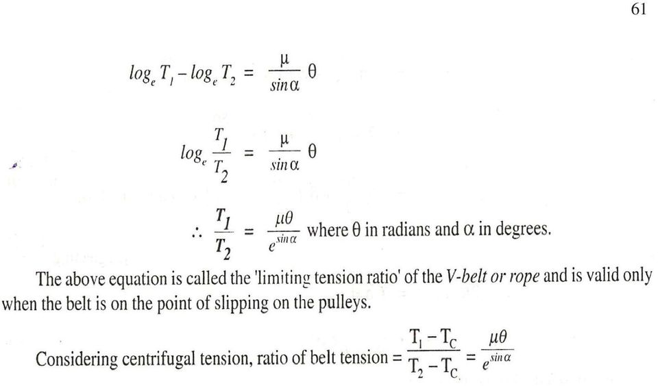
17 58 Ratio of belt tensions for V-belt or rope drive V-Belt drive or rope drive runs in a V-grooved pulley as discussed earlier. The cross-section of V-belt is shown in Figure. Let, 2 = angle of groove RN = normal reaction between each side of groove and the corresponding side of the belt strip PQ From Figure Resolving Forces Vertically, R = RN sin + RN sin = 2 RN sin Total frictional force = RN + RN = 2 RN In case of V-belt or rope, there are two normal reactions as shown in Figure, so that the radial reaction R is 2 RN sin and the total frictional force = 2(µ RN) = 2µ RN Consider a short length PQ of belt subtending angle at the center of the pulley as shown in Figure.

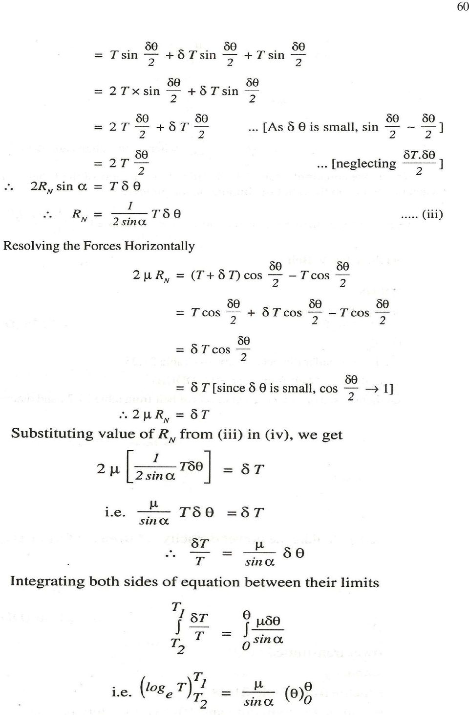
18 59 Let, R = radial reaction between the belt length PQ and the pulley rim = 2RN sin RN = Normal reaction between the belt length PQ and the pulley rim. T = Tension on slack side of the shot strip PQ T+ T = Tension on tight side of short strip PQ T = Difference in tension due to friction between the length PQ and the surface pulley rim µ = Coefficient of friction between the belt and pulley surface µ = effective coefficient of friction = µ/sin The strip PQ will be in equilibrium (figure) under the action of four forces T, T+ T, 2 µrn and R where 2 µrn is the frictional force which is opposing the motion
 under the action of four forces T, T+ T, 2 µrn and R where 2 µrn is the frictional force which is opposing the")
19 60
20 61
21 62 DESIGN PROCEDURE FOR V-BELT 1. Selection of belt c/s Equivalent pitch diameter of smaller pulley de = dp.fb Where, dp = d1 Fb = smaller diameter factor Based on de select the c/s of belt If d is not given them based on power select the c/s of beltand diameter d1 2. Velocity 3. Power capacity Based on the cross-section selected, calculated the power capacity N* from the formulas. 4. Number of V belts N= Total power transmitted in kw N*= power capacity Fa= Service factor If the condition is not given then assume medium duty and hours duty per day. θ θ 1 = 2 cos or D d 2C D d 2C 1 = sin
22 63 Correction factor for angle of contact = Fd (If the type is not given select V - V - Belts) Therefore, Number of belts = i Select a V-belt drive to transmit 10 kw of power froma pulley of 200 mm diameter mounted on an electric motor running at 720 rpm to another pulley mounted on compressor running at 200 rpm. The service is heavy duty varying from 10 hours to 14 hours per day and centre distance between centre of pulleys is 600 mm.
23 64 v. Number of Belts The nearest standard value of nominal pitch length for the selected C-cross section belt L = 2723 mm Nominal inside length = 2667 mm For nominal inside length = 2667 mm, and C-cross section belt, correction factor for length Fe = 0.94
24 65 ROPE DRIVES Introduction When power is to be transmitted over long distances then belts cannot be used due to the heavy losses in power. In such cases ropes can be used. Ropes are used in elevators, mine hoists, cranes, oil well drilling, aerial conveyors, tramways, haulage devices, lifts and suspension bridges etc. two types of ropes are commonly used. They are fiber ropes and metallic ropes. Fiber ropes are made of Manila, hemp, cotton, jute, nylon, coir etc., and are normally used for transmitting power. Metallic ropes are made of steel, aluminium. alloys, copper, bronze or stainless steel and are mainly used in elevator, mine hoists, cranes, oil well drilling, aerial conveyors, haulage devices and suspension bridges. Hoisting tackle (Block and Tackle Mechanism) It consists of two pulley blocks one above the other. Each block has a series of sheaves mounted side by side on the same axle. The ropes used in hoisting tackle are Cotton ropes Hemp ropes and Manila ropes The pulleys are manufactured in two designs i.e. fixed pulley and movable pulley. Pulley system A pulley system is a combination of several movable and fixed pulleys or sheaves. The system can be used for a gain in force or for a gain in speed. Hoisting devices employ pulleys for a gain in force predominantly. Pulley systems for a gain in forces are designed with the rope running off a fixed pulley and with the rope running off a movable pulley. Consider a hoisting tackle (block and tackle mechanism) as shown in fig.
25 66
26 67 STEEL WIRE ROPES A wire rope is made up of stands and a strand is made up of one or more layers of wires as shown in fig. the number of strands in a rope denotes the number of groups of wires that are laid over the central core. For example a 6 19 construction means that the rope has 6 strands and each strand is composed of 19(12/6/1) wires. The central part of the wire rope is called the core and may be of fiber, wire, plastic, paper or asbestos. The fiber core is very flexible and very suitable for all conditions. The points to be considered while selecting a wire rope are Strength Abrasion resistance Flexibility Resistance of crushing Fatigue strength Corrosion resistance. Ropes having wire core are stronger than those having fiber core. Flexibility in rope is more desirable when the number of bends in the rope is too many. DESIGN PROCEDURE FOR WIRE ROPE Let d=diameter of rope D=Diameter of sheave H= Depth of mine or height of building W= total load WR= Weight of rope dw= Diameter of wire A= Area of c/s of rope Pb= Bending load in the rope Fa= allowable pull in the rope Fu= Ultimate of breaking load of rope n= Factor of safety Ws= Starting load
27 68
28 69 problem Select a wire rope to lift a load of 10kN through a height of 600m from a mine. The weight of bucket is 2.5kN. the load should attain a maximum speed of 50m/min in 2 seconds. Solution: From table select the most commonly used type of rope i.e From table for 6 19 rope Fu= d2 N where d in mm Weight per meter length = d2 N/m where d in mm Wire diameter dw = d, mm Area of c/s A = 0.38 d2, mm2 Sheave diameter D= 45 d, mm From table for 600 m depth F.O.S = n = 7 1. Total load W= Load to be lifted + weight of skip = = 12500N
29 70 CHAIN DRIVE Introduction Chain is used to transmit motion from one shaft to another shaft with the help of sprockets. Chain drives maintain a positive speed ratio between driving and driven components, so tension on the slack side is considered is as zero. They are generally used for the transmission of power in cycles, motor vehicles, agricultural machinery, road rollers etc. Merits and demerits of chain drives Merits 1. Chain drives are positive drives and can have high efficiency when operating under ideal conditions. 2. It can de used for both relatively long centre distances. 3. Less load on shafts and compact in size as compared to belt drive. Demerits 1. Relatively high production cost and noisy operation. 2. Chain drives require more amounts of servicing and maintenance as compared to belt drives.
30 71 Velocity ratio in chain drive Let n1= speed of driver sprocket in rpm n2 = speed of driven sprocket in rpm z1= number of teeth on drivers sprocket z2 = number of teeth on driven sprocket Therefore Velocity ratio n1/n2= z1/z2 Chains for power transmission The different types of chain used for power transmission are: i. Block chain ii. Roller chain iii. Inverted-tooth chain or silent chain. ROLLER CHAIN It consists of two rows of outer and inner plates. The outer row of plates in known as pin link or coupling link whereas the inner row of plates is called roller link. A Pin passes through the bush which is secured in the holes of the inner pair of links and is riveted to the outer pair of links as shown in Fig. Each bush is surrounded by a roller. The rollers run freely on the bushes and the bushes turn freely on the pins. A roller chain is extremely strong and simple in construction. It gives good service under severe conditions. To avoid longer sprocket diameter, multi-row-roller chains or chains with multiple strand width are used. Theoretically, the power capacity multistrand chain is equal to the capacity of the single chain multiplied by the number of strand, but actually it is reduced by 10 percent. Inverted tooth chain or silent chain It is as shown Fig. these chains are not exactly silent but these are much smoother and quieter in action than a roller chain. These chains are made up of flat steel stamping, which make it easy to built up any width desired. The links are so shaped that they engage directly with sprocket teeth. In design, the silent chains are more complex than brush roller types, more expensive and require more careful maintenance.
31 72 Chordal action When a chain passes over a sprocket, it moves as a series of chords instead of a continuous arc as in the case of a belt drive. Thus the center line of a chain is not a uniform radius. When the driving sprocket moves at a constant speed, the driven sprocket rotates at a varying speed due to the continually varying radius of chain line. This variation in sped ranges from Where n 1 = Speed of the driving sprocket in rpm d 1 Pitch circle diameter of the driving sprocket in mm z1 = number of teeth on driving sprockets. It is clear from above that for the same pitch, the variation in speed and articulation angle decreases, if the number of teeth in sprocket is increased. The average speed of the sprocket as given by Where p = pitch of the chain in mm and z = number of teeth in sprocket. This chordal action of the chain is shown in Fig.
32 73 DESIGN PROCEDURE FOR ROLLER CHAIN Let p = Pitch d1 = diameter of smaller sprocket d2 = diameter of larger sprocket n1 = speed of smaller sprocket n2 = speed of larger sprocket z1 = number of teeth on smaller sprocket z2 = Number of teeth on larger sprocket L = Length of chain in pitches C = Center diameter Cp = Center distance in pitches 1. Pitch of chain Where p in mm, and n1= speed of smaller sprocket Select standard nearest value of pitch from Table Chain number Breaking load Fu Measuring load w 2. Number of teeth on the sprockets From Table for the given ratio select the number of teeth on the smaller sprocket (z1) Since Number of teeth on larger sprocket = z2 3. Pitch diameters
33 74 = pitch diameter of smaller sprocket = pitch of larger sprocket 4. Velocity 5. Required pull 6. Allowable pull 7. Number of strands in a chain 8. Check for actual factor of safety
34 75 6. Allowable pull 10. length of chain 11. Correct centre distance Select a roller chain drive to transmit power of 10 kw from a shaft rotating at 750 rpm to another shaft to run at 450 rpm. The distance between the shaft centers could be taken as 35 pitches. Data: N= 10 kw; n1 = 750 rpm; n2 = 450 rpm; C = 35 pitches
35 76
36 77
Belt Drives and Chain Drives. Power Train. Power Train
 Belt Drives and Chain Drives Material comes for Mott, 2002 and Kurtz, 1999 Power Train A power train transmits power from an engine or motor to the load. Some of the most common power trains include: Flexible
Mechanical Principles
 Unit 4: Mechanical Principles Unit code: F/60/450 QCF level: 5 Credit value: 5 OUTCOME 3 POWER TRANSMISSION TUTORIAL BELT DRIVES 3 Power Transmission Belt drives: flat and v-section belts; limiting coefficient
SOLID MECHANICS DYNAMICS TUTORIAL PULLEY DRIVE SYSTEMS. This work covers elements of the syllabus for the Edexcel module HNC/D Mechanical Principles.
 SOLID MECHANICS DYNAMICS TUTORIAL PULLEY DRIVE SYSTEMS This work covers elements of the syllabus for the Edexcel module HNC/D Mechanical Principles. On completion of this tutorial you should be able to
B.TECH. (AEROSPACE ENGINEERING) PROGRAMME (BTAE) Term-End Examination December, 2011 BAS-010 : MACHINE DESIGN
 PROGRAMME (BTAE) Term-End Examination December, 2011 BAS-010 : MACHINE DESIGN") No. of Printed Pages : 7 BAS-01.0 B.TECH. (AEROSPACE ENGINEERING) PROGRAMME (BTAE) CV CA CV C:) O Term-End Examination December, 2011 BAS-010 : MACHINE DESIGN Time : 3 hours Maximum Marks : 70 Note : (1)
No. of Printed Pages : 7 BAS-01.0 B.TECH. (AEROSPACE ENGINEERING) PROGRAMME (BTAE) CV CA CV C:) O Term-End Examination December, 2011 BAS-010 : MACHINE DESIGN Time : 3 hours Maximum Marks : 70 Note : (1)
Design of a Rope Brake Dynamometer
 Middle-East Journal of Scientific Research 0 (5): 650-655, 014 ISSN 1990-933 IDOSI Publications, 014 DOI: 10.589/idosi.mejsr.014.0.05.11356 Design of a Rope Brake Dynamometer R. Gopinath Department of
MECHANICAL PRINCIPLES OUTCOME 4 MECHANICAL POWER TRANSMISSION TUTORIAL 1 SIMPLE MACHINES
 MECHANICAL PRINCIPLES OUTCOME 4 MECHANICAL POWER TRANSMISSION TUTORIAL 1 SIMPLE MACHINES Simple machines: lifting devices e.g. lever systems, inclined plane, screw jack, pulley blocks, Weston differential
Highly flexible couplings
 Construction and operation 8.03.00 Instructions for installation 8.03.00 Types of stress 8.04.00 Diagrams for static deformation of the coupling ring 8.05.00 Coupling size 8.07.00 Examples of combinations
Gear Trains. Introduction:
 Gear Trains Introduction: Sometimes, two or more gears are made to mesh with each other to transmit power from one shaft to another. Such a combination is called gear train or train of toothed wheels.
GEAROLOGY 2-1 SPUR GEARS SPUR GEARS
 GEAROLOGY 2-1 2 2-2 GEAROLOGY COMMON APPLICATIONS: Spur gears are used to Now that you ve been introduced to both Boston Gear and some of the basics of our Gearology course which we like to call Power
Formula. = base of natural logarithms. = friction factor of the ropes in the grooves. = angle of wrap of the ropes on the traction sheave (radians).
.") Formula It is generally accepted that the maximum available traction is dependent upon three major factors: i) angle of wrap of the ropes around the traction sheave; ii) shape of groove profile; and iii)
Formula It is generally accepted that the maximum available traction is dependent upon three major factors: i) angle of wrap of the ropes around the traction sheave; ii) shape of groove profile; and iii)
Mechanical Reasoning Review
 Mechanical Reasoning Review Work can be made easier or faster through practical applications of simple and/or compound machines. This is called mechanical advantage - in other words, using the principal
3 Work, Power and Energy
 3 Work, Power and Energy At the end of this section you should be able to: a. describe potential energy as energy due to position and derive potential energy as mgh b. describe kinetic energy as energy
ELEVATOR TRAVELING CABLE - DESIGN EVOLUTION
 ELEVATOR TRAVELING CABLE - DESIGN EVOLUTION by Richard Laney Introduction Elevator traveling cable is a vital link between the elevator car and controller. In conventional elevators, all power and signal
Technology Exploration-I
 Technology Exploration-I PREPARED BY Academic Services August 2011 Applied Technology High Schools, 2011 Module Objectives After the completion of this module, the student should be able to: Identify pulleys.
Fig 1 Power Transmission system of Tractor
 POWER TRANSMISSION SYSTEM Transmission is a speed reducing mechanism, equipped with several gears (Fig. 1). It may be called a sequence of gears and shafts, through which the engine power is transmitted
For New Technology Network. Steel Manufacturing Machinery Product Guide Book
 For New Technology Network R Steel Manufacturing Machinery Product Guide Book Ecological / Economical proposals from NTN NTN products exhibit benefits at various locations. Steel manufacturing equipment
CHAIN CARE & TROUBLE SHOOTING
 Fatigue Failure Bushing Fatigue Stress Corrosion Stress Corrosion and Hydrogen Embrittlement These closely related failures are similar in appearance and nature. They appear as cracks which initiate at
GEAROLOGY 4-1 WORMS AND WORM GEARS WORMS AND WORM GEARS
 GEAROLOGY 4-1 4 4-2 GEAROLOGY COMMON APPLICATIONS: Worm and worm gear sets are used in many, everyday products including: electrical mixers, hubometers, right Now that you have an understanding of two
Module 2- GEARS. Lecture 9 - SPUR GEAR DESIGN
 Module 2- GEARS Lecture 9 - SPUR GEAR DESIGN Contents 9.1 Problem 1 Analysis 9.2 Problem 2 Spur gear 9.1 PROBLEM 1 SPUR GEAR DESIGN In a conveyor system a step-down gear drive is used. The input pinion
Fric-3. force F k and the equation (4.2) may be used. The sense of F k is opposite
 may be used. The sense of F k is opposite") 4. FRICTION 4.1 Laws of friction. We know from experience that when two bodies tend to slide on each other a resisting force appears at their surface of contact which opposes their relative motion. The
4. FRICTION 4.1 Laws of friction. We know from experience that when two bodies tend to slide on each other a resisting force appears at their surface of contact which opposes their relative motion. The
GEARS AND GEAR SYSTEMS
 This file aims to introducing basic concepts of gears and pulleys. Areas covered include spur gears, compound gears, chain drive, rack/pinion systems and pulley systems. GEARS AND GEAR SYSTEMS Gears can
LOW VOLTAGE D.C. MOTORS & GEARBOX UNITS
 LOW D.C. MOTORS & GEARBOX UNITS Printed on 100% recycled paper. 918D SERIES SINGLE RATIO METAL GEARBOX (RE280 MOTOR/RE 280/1 MOTOR) NEW! NEW! NEW! NEW! NEW! WITH 2mm OUTPUT SHAFT (15:1 ONLY) WITH 4mm OUTPUT
Rollers. from the UK s largest roller manufacturer. Quality Performance Reliability
 Rollers from the UK s largest roller manufacturer Quality Performance Reliability 42 Index Gravity Rollers Light to Medium Duty 4 Heavy Duty 5 Plastic Rollers 6 Stainless Steel Rollers 7 Grooved Rollers
Module 2 - GEARS Lecture 7 - SPUR GEAR DESIGN
 Module 2 - GEARS Lecture 7 - SPUR GEAR DESIGN Contents 7.1 Spur gear tooth force analysis 7.2 Spur gear - tooth stresses 7.3 Tooth bending stress Lewis equation 7.4 Tooth bending stress AGMA procedure
EDEXCEL NATIONAL CERTIFICATE/DIPLOMA MECHANICAL PRINCIPLES OUTCOME 2 ENGINEERING COMPONENTS TUTORIAL 1 STRUCTURAL MEMBERS
 ENGINEERING COMPONENTS EDEXCEL NATIONAL CERTIFICATE/DIPLOMA MECHANICAL PRINCIPLES OUTCOME ENGINEERING COMPONENTS TUTORIAL 1 STRUCTURAL MEMBERS Structural members: struts and ties; direct stress and strain,
Machine Design II Prof. K.Gopinath & Prof. M.M.Mayuram. Module 2 - GEARS. Lecture 17 DESIGN OF GEARBOX
 Module 2 - GEARS Lecture 17 DESIGN OF GEARBOX Contents 17.1 Commercial gearboxes 17.2 Gearbox design. 17.1 COMMERCIAL GEARBOXES Various commercial gearbox designs are depicted in Fig. 17.1 to 17.10. These
Technical Data. 7. Bearing Fits. 7.1 Interference. 7.2 Calculation of interference F B LLLLLLLLL( A-54
 Technical Data 7. Bearing Fits 7.1 Interference For rolling s the rings are fixed on the or in the housing so that slip or movement does not occur between the mated surface during operation or under. This
TRANSMISSION CHAIN - SELECTION PROCEDURE
 SELECTION METHOD 1 SELECT DRIVE RATIO AND SPROCKETS INTRODUCTION Chain selected using this method will have a minimum life expectancy with proper installation and lubrication of 15000 hours. The Rating
INVERTED TOOTH Chains and Sprockets FOR POWER TRANSMISSION
 INVERTED TOOTH Chains and Sprockets FOR POWER TRANSMISSION Ramsey Silent Chains For Power Transmission Ramsey Products specializes in the design, manufacture, and application of silent chain drives, also
#25 The Basics of Lightweight Conveyor Belting
 #25 The Basics of Lightweight Conveyor Belting The overall belting market share for lightweight conveyor belting has increased modestly over the past couple of decades. The primary reasons for the increase
DOUBLE DRUM TRACTION WINCH SYSTEMS FOR OCEANOGRAPHIC RESEARCH 1.0 TRACTION WINCH SYSTEM ADVANTAGES 11-2
 Chapter 11 DOUBLE DRUM TRACTION WINCH SYSTEMS FOR OCEANOGRAPHIC RESEARCH James Stasny 1.0 TRACTION WINCH SYSTEM ADVANTAGES 11-2 2.0 THEORY OF OPERATION 11-3 3.0 ADVANTAGES IN TRACTION WINCH SYSTEM DESIGN/
Practice Problems on Boundary Layers. Answer(s): D = 107 N D = 152 N. C. Wassgren, Purdue University Page 1 of 17 Last Updated: 2010 Nov 22
: D = 107 N D = 152 N. C. Wassgren, Purdue University Page 1 of 17 Last Updated: 2010 Nov 22") BL_01 A thin flat plate 55 by 110 cm is immersed in a 6 m/s stream of SAE 10 oil at 20 C. Compute the total skin friction drag if the stream is parallel to (a) the long side and (b) the short side. D =
BL_01 A thin flat plate 55 by 110 cm is immersed in a 6 m/s stream of SAE 10 oil at 20 C. Compute the total skin friction drag if the stream is parallel to (a) the long side and (b) the short side. D =
EDEXCEL NATIONAL CERTIFICATE/DIPLOMA MECHANICAL PRINCIPLES AND APPLICATIONS NQF LEVEL 3 OUTCOME 1 - LOADING SYSTEMS TUTORIAL 3 LOADED COMPONENTS
 EDEXCEL NATIONAL CERTIICATE/DIPLOMA MECHANICAL PRINCIPLES AND APPLICATIONS NQ LEVEL 3 OUTCOME 1 - LOADING SYSTEMS TUTORIAL 3 LOADED COMPONENTS 1. Be able to determine the effects of loading in static engineering
Topics. Introduction Gear schematics Types of gears Measuring gears
 Gear Measurement Topics Introduction Gear schematics Types of gears Measuring gears What is a gear? A gear is a wheel with teeth that mesh together with other gears. Gears change the : speed torque (rot.
BAGGAGE HANDLING SYSTEMS. Trastecnica S.p.A. Handling Baggage Systems Edition 2002 - Rev. 00-1 -
 BAGGAGE HANDLING SYSTEMS Trastecnica S.p.A. Handling Baggage Systems Edition 2002 - Rev. 00-1 - TECHNICAL SPECIFICS INDEX Check-in with one conveyor 4 Scales 6 Belt Conveyors 8 Take away 9 Feeder and Belt
Boom and fly capacities for this machine are listed by the following sections:
 Lifting Capacities Telescopic Hydraulic Truck Crane HTC 8650 50 ton (45.36 metric ton) and fly capacities for this machine are listed by the following sections: Fully Extended Outriggers Working Range
Roller Chain Drive Design
 Roller Chain Drive Design Roller Chain by nature of its design is capable of transmitting high torque loads, and provides the ideal drive media for the connection of slow to medium speed shafts located
Belt and Roller Conveyor for boxes and containers
 logiss srl 38068 Rovereto (TN) Italy Viale del Lavoro, 16/E (ZI) Tel. +39 0464 401121 Fax. +39 0464 423077 Mail [email protected] Web Belt and Roller Conveyor for boxes and containers A wide range of
There are four types of friction, they are 1).Static friction 2) Dynamic friction 3) Sliding friction 4) Rolling friction
.Static friction 2) Dynamic friction 3) Sliding friction 4) Rolling friction") 2.3 RICTION The property by virtue of which a resisting force is created between two rough bodies that resists the sliding of one body over the other is known as friction. The force that always opposes
2.3 RICTION The property by virtue of which a resisting force is created between two rough bodies that resists the sliding of one body over the other is known as friction. The force that always opposes
BELT AND CHAIN DRIVES
 BELT AND CHAIN DRIVES BELT DRIVES BELT DRIVES...A105 CHAIN DRIVES...A109 BELT AND CHAIN DRIVES ADVERTISING...A115 sign, and delivery priorities prevail for belts and sheaves for industrial machines built
MACHINE TOOL DRIVES. Learning Objectives:
 MACHINE TOOL DRIVES Learning Objectives: Broadly Classification of transmission of rotary motion Stepped Speed Drives in Machine Tools Belting Pick-Off Gears Gear boxes AP &GP for steeping speeds of gears
Numerical Analysis of Independent Wire Strand Core (IWSC) Wire Rope
 Wire Rope") Numerical Analysis of Independent Wire Strand Core (IWSC) Wire Rope Rakesh Sidharthan 1 Gnanavel B K 2 Assistant professor Mechanical, Department Professor, Mechanical Department, Gojan engineering college,
Numerical Analysis of Independent Wire Strand Core (IWSC) Wire Rope Rakesh Sidharthan 1 Gnanavel B K 2 Assistant professor Mechanical, Department Professor, Mechanical Department, Gojan engineering college,
ENGINEERING COUNCIL CERTIFICATE LEVEL
 ENGINEERING COUNCIL CERTIICATE LEVEL ENGINEERING SCIENCE C103 TUTORIAL - BASIC STUDIES O STRESS AND STRAIN You should judge your progress by completing the self assessment exercises. These may be sent
Q&A Session for Advanced Ball Screws 102: Troubleshooting for Design Engineers
 Q&A Session for Advanced Ball Screws 102: Troubleshooting for Design Engineers Topic: Noise Q: Is there a way to predict/calculate noise on a ball screw? A: No, there is no way to calculate the noise of
The Campbell operation facilities in York, PA, and Cortland, NY, conform to Quality Standard ISO 9001.
 Campbell Blocks Table of Contents Begun as a forging company in 1834, Campbell/Brewer-Titchener first manufactured horse harnesses, then carriage hardware, then horseless carriage hardware. From hardware
The word teamster today means a truck driver,
 Page 47 Heron of Alexandria The word teamster today means a truck driver, but originally it meant a wagon driver, someone who drives a team of horses, mules or oxen. Over 2000 years ago teamsters in the
Servo Motor Selection Flow Chart
 Servo otor Selection Flow Chart START Selection Has the machine Been Selected? YES NO Explanation References etermine the size, mass, coefficient of friction, and external forces of all the moving part
Solution Derivations for Capa #11
 Solution Derivations for Capa #11 1) A horizontal circular platform (M = 128.1 kg, r = 3.11 m) rotates about a frictionless vertical axle. A student (m = 68.3 kg) walks slowly from the rim of the platform
DryLin ZLW Belt Drive
 Belt Drive +50º 0º DryLin toothed belt drives have been developed for the fast positioning of small loads. The linear units with toothed belt drive are corrosion resistant, light and compact, besides having
MECHANICAL PRINCIPLES HNC/D PRELIMINARY LEVEL TUTORIAL 1 BASIC STUDIES OF STRESS AND STRAIN
 MECHANICAL PRINCIPLES HNC/D PRELIMINARY LEVEL TUTORIAL 1 BASIC STUDIES O STRESS AND STRAIN This tutorial is essential for anyone studying the group of tutorials on beams. Essential pre-requisite knowledge
BICO CHIPMUNK JAW CRUSHER - TYPE WD
 BICO CHIPMUNK JAW CRUSHER - TYPE WD The Bico Chipmunk Jaw Crusher is designed to give long and efficient service. In order to secure the long life and excellent performance that your crusher is capable
SURFACE TENSION. Definition
 SURFACE TENSION Definition In the fall a fisherman s boat is often surrounded by fallen leaves that are lying on the water. The boat floats, because it is partially immersed in the water and the resulting
Lapping and Polishing Basics
 Lapping and Polishing Basics Applications Laboratory Report 54 Lapping and Polishing 1.0: Introduction Lapping and polishing is a process by which material is precisely removed from a workpiece (or specimen)
PowerLine Magnetic-Laser Pulley Alignment System Instructions
 MONARCH INSTRUMENT 15 COLUMBIA DRIVE AMHERST, NEW HAMPSHIRE 03031 PHONE: 603-883-3390 FAX: 603-886-3300 E-mail: [email protected] Web site: www.monarchinstrument.com PowerLine Magnetic-Laser
WINDER SYSTEMS GE Industrial Control Systems
 WINDER SYSTEMS Systems Concepts Terminology GE Industrial Control Systems APPLICATION TECHNIQUES With a smooth metal surface material, a paper liner is sometimes wound with a coil. The paper is lightweight
TECHNICAL INFORMATION
 TECHNICAL INFORMATION Models No. 2012NB Description 304mm (12") Automatic Thickness Planer CONCEPTION AND MAIN APPLICATIONS * Compact and light weight (27 Kg./59 lbs) automatic thickness planer for easier
DRAFTING MANUAL. Gears (Bevel and Hypoid) Drafting Practice
 Drafting Practice") Page 1 1.0 General This section provides the basis for uniformity in engineering gears drawings and their technical data for gears with intersecting axes (bevel gears), and nonparallel, nonintersecting
Page 1 1.0 General This section provides the basis for uniformity in engineering gears drawings and their technical data for gears with intersecting axes (bevel gears), and nonparallel, nonintersecting
7.3 Fit selection. Inner ring: Rotating. Outer ring: Stationary. Inner ring: Stationary. Outer ring: Rotating. Inner ring: Stationary
 7. Bearing Fits 7. Fitting For rolling s, inner and outer rings are fixed on the or in the housing so that relative movement does not occur between fitting surfaces during operation or under. This relative
Problem Set 1. Ans: a = 1.74 m/s 2, t = 4.80 s
 Problem Set 1 1.1 A bicyclist starts from rest and after traveling along a straight path a distance of 20 m reaches a speed of 30 km/h. Determine her constant acceleration. How long does it take her to
Electric Motors and Drives
 EML 2322L MAE Design and Manufacturing Laboratory Electric Motors and Drives To calculate the peak power and torque produced by an electric motor, you will need to know the following: Motor supply voltage,
What is a Mouse-Trap
 What is a Mouse-Trap Car and How does it Work? A mouse-trap car is a vehicle that is powered by the energy that can be stored in a wound up mouse-trap spring. The most basic design is as follows: a string
Shaft- Mounted Speed Reducers
 Torque Arm Design Considerations for Todd R. Bobak has worked in the gear industry for 15 years. He has held positions in technical service, design and development, and quality assurance. He is a product
Gear Engineering Data. Spur Gear Gear Formulas Drive Selection Horsepower and Torque Tables
 Engineering Gear Engineering Data Spur Gear Gear Formulas Drive Selection Horsepower and Torque Tables G-79 Gear Selection Stock Spur Gear Drive Selection When designing a stock gear drive using the horsepower
ANSWER KEY. Work and Machines
 Chapter Project Worksheet 1 1. inclined plane, wedge, screw, lever, wheel and axle, pulley 2. pulley 3. lever 4. inclined plane 5. Answers will vary: top, side, or bottom 6. Answers will vary; only one
SECTION 4 CONVEYOR CHAIN DESIGNER GUIDE. 66 engineering excellence www.renold.com
 SECTION CONVEYOR CHAIN DESIGNER GUIDE 66 engineering excellence www.renold.com Introduction Selecting the right chain for a given application is essential to obtain long service life. This guide has been
AS COMPETITION PAPER 2008
 AS COMPETITION PAPER 28 Name School Town & County Total Mark/5 Time Allowed: One hour Attempt as many questions as you can. Write your answers on this question paper. Marks allocated for each question
ROLL PASS DESIGN EVAULUATION USING SOFTWARE APPLICATION ARINDAM MUKHERJEE PROJECT MANAGEMENT CELL UNDP/GEF PROJECT (STEEL)
") ROLL PASS DESIGN EVAULUATION USING SOFTWARE APPLICATION ARINDAM MUKHERJEE PROJECT MANAGEMENT CELL UNDP/GEF PROJECT (STEEL) OBJECTIVE OF ROLL PASS DESIGN Steel sections are generally rolled in several passes,
ROLL PASS DESIGN EVAULUATION USING SOFTWARE APPLICATION ARINDAM MUKHERJEE PROJECT MANAGEMENT CELL UNDP/GEF PROJECT (STEEL) OBJECTIVE OF ROLL PASS DESIGN Steel sections are generally rolled in several passes,
Roller Chain Coupling
 Roller Chain Coupling Features 1. Simple structure A roller chain coupling consists of one duplex roller chain and two sprockets for a simplex chain. Handling is very simple as both the shafts (driving
Belt Tensioning Methods for Small Package Conveyors What s the best solution?
 Belt Tensioning Methods for Small Package Conveyors What s the best solution? Industrial White Paper By: Michael A. Hosch, P.E. Dorner Mfg. Corp. 975 Cottonwood Avenue Hartland, WI 53029 USA Phone: 800
The flat belt drive compared to the V-belt drive
 Edition: October 2001 Replaces edition: January 1992 Informa Manual The flat belt drive compared to the V-belt drive 9130 The flat belt drive The V-belt drive Table of contents 2 page Introduction 1. The
CHAPTER 15 FORCE, MASS AND ACCELERATION
 CHAPTER 5 FORCE, MASS AND ACCELERATION EXERCISE 83, Page 9. A car initially at rest accelerates uniformly to a speed of 55 km/h in 4 s. Determine the accelerating force required if the mass of the car
www.mathsbox.org.uk Displacement (x) Velocity (v) Acceleration (a) x = f(t) differentiate v = dx Acceleration Velocity (v) Displacement x
 Velocity (v) Acceleration (a) x = f(t) differentiate v = dx Acceleration Velocity (v) Displacement x") Mechanics 2 : Revision Notes 1. Kinematics and variable acceleration Displacement (x) Velocity (v) Acceleration (a) x = f(t) differentiate v = dx differentiate a = dv = d2 x dt dt dt 2 Acceleration Velocity
Mechanics 2 : Revision Notes 1. Kinematics and variable acceleration Displacement (x) Velocity (v) Acceleration (a) x = f(t) differentiate v = dx differentiate a = dv = d2 x dt dt dt 2 Acceleration Velocity
Service life of synthetic fibre ropes in deepwater lifting operations. The 15 th North Sea Offshore Cranes & Lifting Conference Ashley Nuttall
 Service life of synthetic fibre ropes in deepwater lifting operations The 15 th North Sea Offshore Cranes & Lifting Conference Ashley Nuttall Fibre ropes for deepwater lifting Fibre ropes offer the following
Chapter 18: Brakes and Clutches
 Chapter 18: Brakes and Clutches Nothing has such power to broaden the mind as the ability to investigate systematically and truly all that comes under thy observation in life. Marcus Aurelius, Roman Emperor
v v ax v a x a v a v = = = Since F = ma, it follows that a = F/m. The mass of the arrow is unchanged, and ( )
") Week 3 homework IMPORTANT NOTE ABOUT WEBASSIGN: In the WebAssign versions of these problems, various details have been changed, so that the answers will come out differently. The method to find the solution
Week 3 homework IMPORTANT NOTE ABOUT WEBASSIGN: In the WebAssign versions of these problems, various details have been changed, so that the answers will come out differently. The method to find the solution
Overall Indicator: The student: recognizes the effects of forces acting on structures and mechanisms
 Grade 5 Performance Task: Disaster Recovery Content Connections Assessment Criterion Understanding of basic concepts Overall Indicator: The student: recognizes the effects of forces acting on structures
Unit 24: Applications of Pneumatics and Hydraulics
 Unit 24: Applications of Pneumatics and Hydraulics Unit code: J/601/1496 QCF level: 4 Credit value: 15 OUTCOME 2 TUTORIAL 2 HYDRAULIC AND PNEUMATIC CYLINDERS The material needed for outcome 2 is very extensive
ULTRA 865HD HIGH PERFORMANCE MULTI PURPOSE GREASE
 ULTRA 865HD HIGH PERFORMANCE MULTI PURPOSE GREASE Contains penetrants, lubricants and greases All weather Water-resistant Penetrates like an oil, then cures to a thick, water-resistant grease Recommended
Residential Garage Door Terminology
 A Air Infiltration: The leakage or passage of air through a door system Anodize: A hard non-corrosive oxide film on the surface of aluminum Astragal: A compressible or deformable seal provided on the bottom
SOLID MECHANICS DYNAMICS TUTORIAL MOMENT OF INERTIA. This work covers elements of the following syllabi.
 SOLID MECHANICS DYNAMICS TUTOIAL MOMENT OF INETIA This work covers elements of the following syllabi. Parts of the Engineering Council Graduate Diploma Exam D5 Dynamics of Mechanical Systems Parts of the
Simple Machines. What are simple machines?
 Definitions to know: Simple Machines Work done when an applied force causes an object to move in the direction of the force Energy ability to cause change; can change the speed, direction, shape, or temperature
Prelab Exercises: Hooke's Law and the Behavior of Springs
 59 Prelab Exercises: Hooke's Law and the Behavior of Springs Study the description of the experiment that follows and answer the following questions.. (3 marks) Explain why a mass suspended vertically
Contents. ELATECH Polyurethane belts 2. ELATECH M and V 3. ELA-flex SD Polyurethane belts 95. Polyurethane belts for conveying applications 125
 ELATECH Polyurethane belts 2 Introduction to ELATECH polyurethane belts 2 Page Contents ELATECH M and V 3 Introduction 4 Tension cords 4 Products certifications 4 Mechanical and chemical properties 4 Executions
DESIGN OF SLABS. 3) Based on support or boundary condition: Simply supported, Cantilever slab,
 Based on support or boundary condition: Simply supported, Cantilever slab,") DESIGN OF SLABS Dr. G. P. Chandradhara Professor of Civil Engineering S. J. College of Engineering Mysore 1. GENERAL A slab is a flat two dimensional planar structural element having thickness small compared
DESIGN OF SLABS Dr. G. P. Chandradhara Professor of Civil Engineering S. J. College of Engineering Mysore 1. GENERAL A slab is a flat two dimensional planar structural element having thickness small compared
PowerLine Magnetic-Laser Sheave Alignment System Instructions
 PowerLine Magnetic-Laser Sheave Alignment System Instructions The PowerLine Magnetic-Laser Sheave Alignment System laser aligns belts, pulleys, sheaves, sprockets, gear trains, rollers, platforms, conveyors,
EVALUAT ING ACADEMIC READINESS FOR APPRENTICESHIP TRAINING Revised for ACCESS TO APPRENTICESHIP
 EVALUAT ING ACADEMIC READINESS FOR APPRENTICESHIP TRAINING for ACCESS TO APPRENTICESHIP SCIENCE SKILLS SIMPLE MACHINES & MECHANICAL ADVANTAGE AN ACADEMIC SKILLS MANUAL for The Construction Trades: Mechanical
Network Standard Advice No. 1420C 9/6/2011
 Network Standard Advice No. 1420C 9/6/2011 TO: Customers, Service Providers and Ausgrid Staff. Advisory Note on Changes to the Use of 11kV Cable Types. Introduction This Network Standard Advice (NSA) provides
SKF Transmission chains
 SKF ransmission chains 2 Contents A A Introduction Standards and compliance... 3 Chain parts... 14 B Selection and procedures Chain selection procedure and design guidelines... 10 ower rating tables..................................
TARIFF CODE and updates standard
 TARIFF CODE and updates standard No HS CODE AHTN CODE PRODUCT DESCRIPTION PRODUCT TYPE STANDARDS IDENTIFIED 7207 Semi finished products of iron or non alloy steel Containing by weight less than 0.25% of
Simple Machines. Figure 2: Basic design for a mousetrap vehicle
 Mousetrap Vehicles Figure 1: This sample mousetrap-powered vehicle has a large drive wheel and a small axle. The vehicle will move slowly and travel a long distance for each turn of the wheel. 1 People
105 Webster St. Hanover Massachusetts 02339 Tel. 781 878 1512 Fax 781 878 6708
 105 Webster St. Hanover Massachusetts 02339 Tel. 781 878 1512 Fax 781 878 6708 Chain Drive Systems Description In order to design, build and discuss chain drive systems it is necessary to understand the
2. Crane standing on firm, horizontal ground.
 The operating weight includes the basic machine with HD undercarriage, 2 main winches 300 kn with speed change gear and 11 m boom, consisting of A frame, boom foot (4 m), boom head section (6.4 m), boom
Ideal Cable. Linear Spring - 1. Cables, Springs and Pulleys
 Cables, Springs and Pulleys ME 202 Ideal Cable Neglect weight (massless) Neglect bending stiffness Force parallel to cable Force only tensile (cable taut) Neglect stretching (inextensible) 1 2 Sketch a
ROSTA MOTORBASES ROSTA. Self-Tensioning Motor Mount for Belt Drives. without slippage self-adjusting maintenance-free
 MOTORBASES Self-Tensioning Motor Mount for Belt Drives without slippage self-adjusting maintenance-free ROSTA Technology ROSTA Tensioning Motorbase Type MB for Belt Drives The ROSTA elastic tensioning
Journal bearings/sliding bearings
 Journal bearings/sliding bearings Operating conditions: Advantages: - Vibration damping, impact damping, noise damping - not sensitive for vibrations, low operating noise level - dust tight (if lubricated
MECHANICS OF SOLIDS - BEAMS TUTORIAL 1 STRESSES IN BEAMS DUE TO BENDING. On completion of this tutorial you should be able to do the following.
 MECHANICS OF SOLIDS - BEAMS TUTOIAL 1 STESSES IN BEAMS DUE TO BENDING This is the first tutorial on bending of beams designed for anyone wishing to study it at a fairly advanced level. You should judge
Fluid Mechanics: Static s Kinematics Dynamics Fluid
 Fluid Mechanics: Fluid mechanics may be defined as that branch of engineering science that deals with the behavior of fluid under the condition of rest and motion Fluid mechanics may be divided into three
LiftAlloy Chain Slings
 CHAIN SLING BASICS Slings Lift-All chain slings meet or exceed all OSHA, ASME B30.9 and NACM standards and regulations. chain slings, available in 80 for 7/32" and 7/8"- /4" and 00 for 9/32"-3/4", are
Motion. Table of Contents: Introduction to the Motion Subsystem 3.2. Concepts to Understand 3.8. Subsystem Interactions 3.26. Motion.
 Motion Table of Contents: Introduction to the Motion Subsystem 3.2 Concepts to Understand 3.8 Subsystem Interactions 3.26 3 1 Introduction to the Motion Subsystem The Motion Subsystem comprises all the