Reliable System Solutions for Isolated Air-Termination Systems.
|
|
|
- Myles Young
- 9 years ago
- Views:
Transcription
1 Lightning Protection Surge Protection Safety Equipment DEHN + SÖHNE GmbH + Co.KG. Hans-Dehn-Str. 1 Postfach Neumarkt Germany Reliable System Solutions for Isolated Air-Termination Systems. Tel Fax [email protected] For more information material and services e.g. Lightning Protection main catalogue DEHNsupport Toolbox Lightning Protection Guide Appointment with our sales engineer please visit our homepage: Service section COPYRIGHT 2010 DEHN + SÖHNE DS151/E/0810

2 supporting tube with in the hazardous area supporting tube with at a cell site mast isolated air-termination rod with tripod DEHNiso spacer telescopic lightning protection mast isolated air-termination rod with concrete base air-termination tip with MV clamp Part No DEHNiso Combi DEHNiso Combi modular, versatile and robust. DEHNiso Combi set Part No supporting tube Part No DEHNiso Combi is a practice-oriented, modular and flexible component programme which meets the mechanical and constructive requirements on site. The components of the DEHNiso Combi system allow to use isolated air-termination systems for complex contours of the volume to be protected. Electrical and metal installations protruding above the roof are protected against lightning strokes and coupling of parts of the lightning current into the building is prevented. If the separation distance s is considered, an uncontrolled flashover (sparks) can be prevented and partial lightning currents cannot enter the building/installation. The separation distance can be calculated based on EN The DEHNiso Combi programme allows for installation of the following components: Air-termination rods with conical protection zone, Four and more air-termination rods with a large protection zone, Isolated air-termination systems with tripod. Pipes or profile systems, walls or corners: the fixing system of the DEHNiso Combi component programme offers solutions for every application. An insulating piece in the supporting tube and a glass-fibre reinforced plastic spacer bar allow for maintaining the separation distance. Bars come in standard lengths and individually adjustable lengths and are mounted firmly or can be inserted into a fixing socket. A material factor km = 0.7 is used for determining the separation distance (length of the spacer bar). Besides the standard air-termination rod support, supports for wires are also available. Tripods with fixed terminals (concrete base) can be used for installing isolated air-termination rods which have to withstand high wind loads. The DEHNiso Combi system allows for easy installation of isolated air-termination systems. tensioning strap for pipes and masts Part No mounting bracket for even installation locations Part No For the entire DEHNiso Combi programme and additional technical information, please refer to our Lightning Protection main catalogue and to installation instructions 1475.

3 DEHNiso Combi

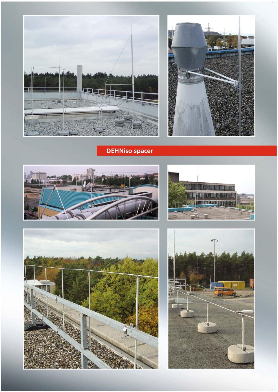
4 supporting tube with in the hazardous area supporting tube with at a cell site mast isolated air-termination rod with tripod DEHNiso spacer telescopic lightning protection mast isolated air-termination rod with concrete base spacer with twin screw cleat and fixing plate (also suitable for flat structures) Part No spacer with pipe clamp for fixation at round components Part No DEHNiso Combi DEHNiso spacer versatile, durable and elegant. The DEHNiso spacer system is a practice-oriented and versatile component programme. This system offers easy and cost-effective solutions for almost every application. The spacer system can be used as static support for isolated air-termination rods (diameter 16 mm). Provided that the separation distance s (material factor km = 0.7) is observed, the installation of ring conductors is also possible. Thus, e.g. an air-termination rod (diameter 16 mm) can be directly attached to the structure to be protected via spacers if the separation distance is maintained. The relevant down conductor can also be installed directly at the structure to be protected by means of spacers. Standard lengths up to 1 m with pre-mounted fixing elements and premounted conductor holders and/or rod holders are available. If special lengths are required, spacers can be assembled of 3 m rods and the relevant individual components. Even though projects requirements are versatile, installation vehicles have only limited loading capacities. Therefore, DEHN + SÖHNE does not only offer set solutions but also a modular DEHNiso system. pipe clamp with fixing socket for spacer bar ø 16 mm Part No angle fixing with clamping bolt for spacer bars ø 16 mm Part No spacer with rod holder Part No spacer bar (can be cut to length for variable solutions, l = 3 m) Part No adapter for angled support for robust fixation of airtermination rods Part No For the entire DEHNiso Combi spacer programme and additional technical information, please refer to our Lightning Protection main catalogue.

5 DEHNiso spacer
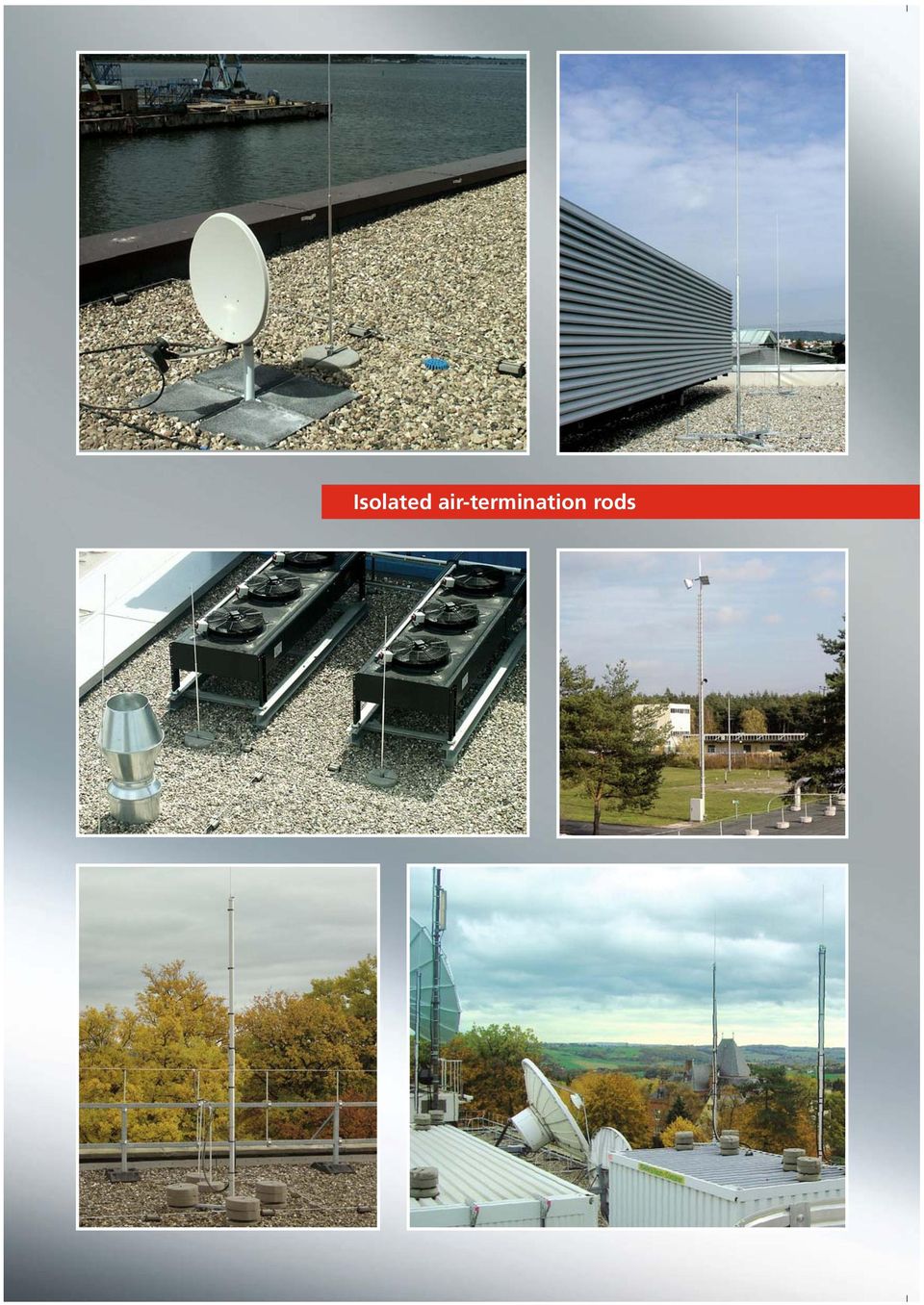
6 supporting tube with HVI conductor in the hazardous area air-termination tip Part No supporting tube with isolated airtermination rod with tripod DEHNiso spacer at a cell site mast isolated air-termination rod with concrete base telescopic lightning protection mast isolated air-termination rod with braces m Part No isolated air-termmination rod with tripod 12 m / 14 m Part No / DEHNiso Combi Isolated air-termination rods easy to install, stable and weight-optimised. Isolated air-termination rods allow integration of large superstructures into protection zone 0B without mechanically contacting or drilling installations with roof superstructures, air conditioning systems or fans. Air-termination rods can be inserted into tripods which are positioned on the roof area or on the ground. Stability has to be ensured considering the wind load zones and wind velocities stipulated by the relevant standard. The map shows that approximately 95% of the surface of Germany is covered by wind zones I and II. For this reason, air-termination rods are generally designed for wind zone II. Depending on the occurring loads, it has to be verified separately if isolated air-termination rods can be used in wind zones III and IV. spacer Part No DEHNiso Combi supporting tube Part No isolated air-termination rod available from 4 m to 5.5 m Part No wedged concrete base Part No base plate for concrete base Part No tripod for DEHNiso Combi supporting tube Part No For the complete DEHNiso air-termination rod programme and additional technical information, please refer to our Lightning Protection main catalogue and to installation instructions 1436.

7 Isolated air-termination rods
8 supporting tube with in the hazardous area DEHN telescopic lightning protection mast in a bucket or concrete foundation supporting tube with a cell site mast The masts are installed on site in a bucket foundation (finished part) or in a concrete foundation with a foundation basket (to be ordered separately). For more detailed information on the plug-in system, foundation and installation, please refer to our lightning protection catalogue. The masts are dimensioned for wind speeds up to 161 km/h (wind load zone III in accordance with DIN 4131). DEHNiso spacer isolated air-termination rod with tripod DEHNiso Combi isolated air-termination rod with concrete base telescopic lightning protection mast Benefits of the air-termination mast system: Excavation work can be completed in advance Installation on site in a bucket foundation (finished part) with little effort or Alternatively installation on site in a concrete foundation with a foundation basket (hardening time of concrete has to be considered for time scheduling and installation) Type with flange plate for fast installation Easy positioning due to M24 threaded bolt Detailed installation instructions Verifiable statics (on request) Max. transport length of 6 m. DEHN telescopic lightning protection masts easy to transport, practical and cost-effective. Available with a height above ground from m to m. Part No For more detailed information, please refer to installation instructions No It is useful to apply the protective angle method to plain buildings. The values of the protective angle depend on the class of LPS and the height of the air-termination rod. The separation distance s between the air-termination rod and the structure to be protected has to be observed in accordance with EN The telescopic lightning protection masts come in different lengths. Bucket foundations for telescopic lightning protection masts Bucket foundation (finished part) for easy installation of telescopic lightning protection masts. No concrete work required on site. Part No and DEHN telescopic lightning protection mast with screw-in foundation The masts are installed with a screw-in foundation. No digging or foundation work is necessary. Without special preparation the screw-in foundation is just screwed into the ground and fixed additionally with earth rods. The masts are designed for wind velocities up to 145 km/h (wind load zone II according to DIN 4131). Height above ground from 6 m to 11 m. Part No For further details, please see also installation instructions No Foundation baskets for concrete foundation on site To be encased in concrete, with threaded bolt, compatible with the flange plate of the telescopic lightning protection masts. For more technical information, please refer to our Lightning Protection main catalogue. Part No and
.")
9 Source: AW Elektro Automatisierungstechnik, Stadtlohn / Germany DEHN telescopic lightning protection masts Source: Bischof Blitzschutz, Weyhe / Germany

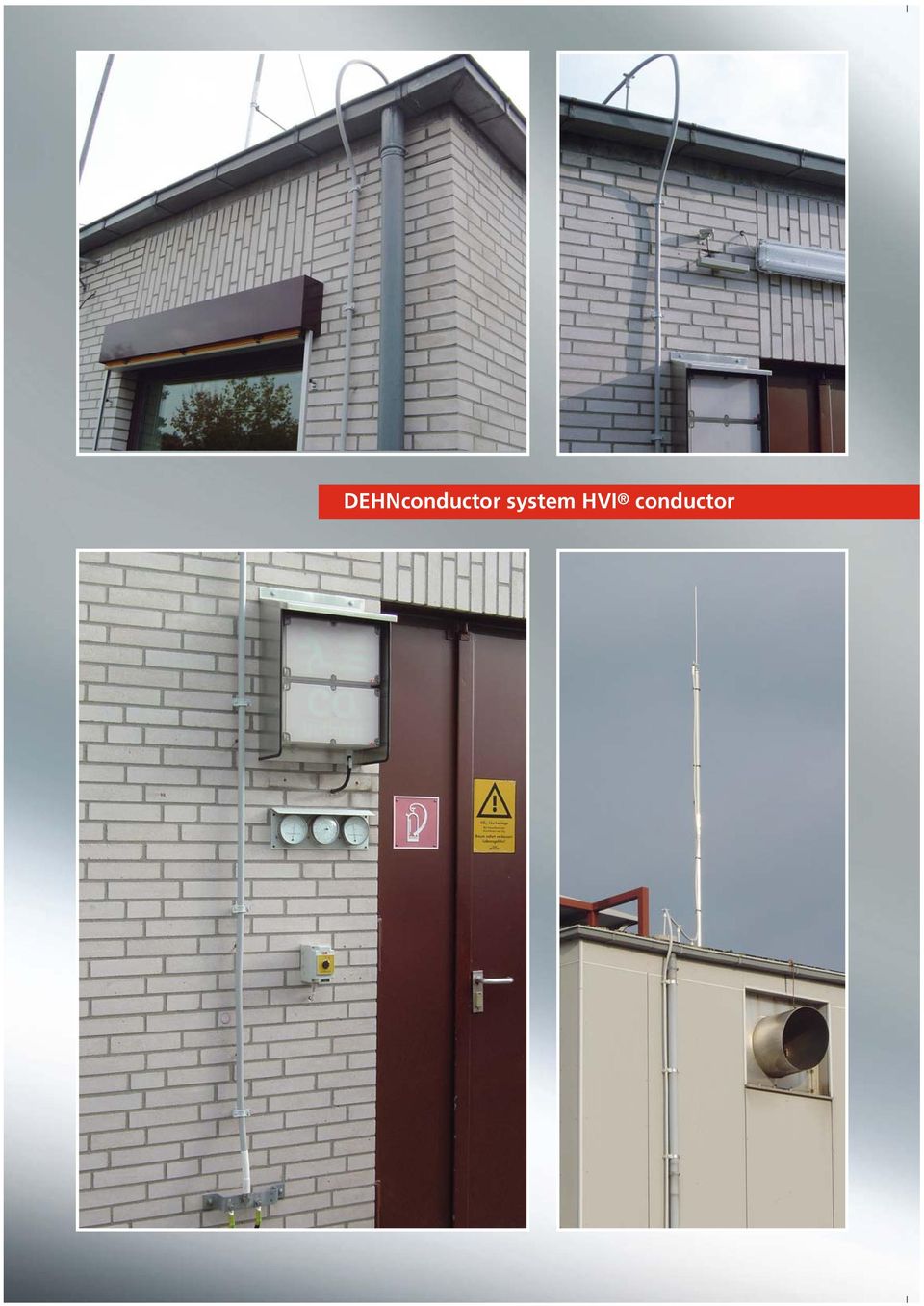
10 supporting tube with in the hazardous area supporting tube with at a cell site mast isolated airtermination rod with tripod HVI conductor in the supporting tube Part No DEHNiso spacer isolated air-termination rod with concrete base telescopic lightning protection mast DEHNiso Combi head piece DEHNconductor system durable, universal, tried and tested. High impulse voltages cause flashovers at the surface of insulating materials if no additional protection measures are taken. This effect is known as creeping flashover. If the creeping discharge inception voltage is exceeded, a surface discharge occurs which may range over a distance of several metres without any problems. In order to avoid creeping discharges, the HVI conductor is equipped with a special external coating which allows for diverting high lightning impulse voltages to a reference potential. In the sealing end area, the external special coating is connected to the equipotential bonding structure of the building where no parts of the lightning current flow, e.g. at earthed metal roof superstructures in the protection zone of the lightning protection system, at earthed parts of the building construction which are free of lightning currents or at the protective conductor of the low-voltage system. Under certain conditions, the special coating can be connected to parts of the lightning protection system such as air-termination system and other down conductors. For this purpose, it has to be ensured that the calculated separation distance does not exceed 35 cm in air at the contact point. In this case, the special external coating has to be directly connected to the part through which lightning potential flows via an equipotential bonding connection element. The black coaxial with an outer diameter of 20 mm and the grey coaxial with an outer diameter of 23 mm consist of a 19 mm 2 copper wire, a thick-walled, high-voltage-resistant insulation and a weatherproof special external coating. In order to prevent lowenergy flashovers due to capacitive displacement currents, the can be additionally connected to the equipotential bonding structure during conductor installation. These connections do not have to be capable of carrying lightning currents as the capacitive displacement currents have low energy and do not cause dangerous sparking. Extensive measurements show that the with its high electric strength has an equivalent separation distance of s = 0.75 m (air). head piece sealing end area EB connection element (fixed) with special coating earth connection element (not fixed) sealing end area EB connection element (fixed) sealing end area head piece head piece sealing end area EB connection element (fixed) with special coating heat-shrinkable sleeve (not fixed) earth connection element (not fixed) EB connection element (not fixed) I Part No II Part No III Part No and supporting tube for biogas plants Part No For more technical information, please refer to our Lightning Protection main catalogue and to installation instructions spacer for supporting tubes at omnidirectional antennas Part No

11 DEHNconductor system
12 Product range of the. The prewired I is equipped with a head piece and an earth connection element at delivery. The earth connection element is pre-mounted in its delivery condition. Thus, the length of the can be adjusted (shortened) on site and the earth connection element can be installed. I is used e.g. for directly connecting the air-termination system to the earth-termination system of the structure. An equipotential bonding element is firmly attached at the end of the sealing end area for the connection of the to the equipotential bonding (EB) structure. At delivery, the prewired II is equipped with two adjusted head pieces the length of which cannot be changed on site. The prewired III is equipped with a fixed sealing end consisting of a head piece and a fixed equipotential bonding element. An additional sealing end at the end of the conductor can be established on site. The components required for this (connection element with heat-shrinkable sleeve and equipotential bonding element) are not fixed at delivery. This allows for adjusting the length of III on site. s II and III are used if e.g. several parts of a plant to be protected are not supposed to be connected individually but jointly to the earth-termination system of the structure via a separate ring conductor (consideration of the separation distance). The can also be installed in the supporting tube at locations with special architectural requirements. Isolated air-termination systems for antennas and emitting characteristics / omnidirectional antennas. Protection of omnidirectional antennas e.g. I in supporting tube Part No L = 3200 mm e.g. I in supporting tube Part No L = 3200 mm Antennas with 360 emitting characteristics (omnidirectional antennas) are used for different radio applications. When installing isolated air-termination systems for omnidirectional antennas, it has to be considered that an isolated air-termination rod with a sufficient protective angle covers the antenna to be protected. Furthermore it has to be ensured that a sufficient separation distance is maintained. From a functional point of view, a distance has to be kept between the antenna and the air-termination system, which corresponds to a quarter of the wave length of the radio frequency used. Installation instructions No have to be observed. Units: Hz m Frequency [F] Wave length [ ] x x x x x Covered by DEHN spacers for omnidirectional antennas.

13 50 mm supporting tube with in the hazardous area = DEHNconductor system in the hazardous area approved and certified. DEHNconductor system HVI conductor Special measures have to be taken to protect all industrial sectors against explosion in which the processing or transport of combustible substances causes gases, vapours, mist or dusts creating a potentially explosive atmosphere with air. Depending on the probability and duration of the occurrence of potentially explosive atmospheres, the areas of the potentially explosive system are divided into zones which are referred to as hazardous areas. Annex D of EN provides detailed information on lightning protection systems for potentially explosive systems taking into consideration threats posed by direct and indirect lightning strokes, causes of damage, structures to be protected and protection measures to be taken. Due to the ever increasing complexibility of systems, effective protection in case of lightning strokes and surges becomes more and more important. Legislation e.g. the Landesbauordnungen (German building regulations) and Betriebssicherheitsverordung (German Health and Safety at Work Regulations) calls for lightning protection measures for structures housing potentially explosive facilities such as paint facilities, chemical facilities, large warehouses with combustible liquids and large gas tanks with a high fire risk. The DEHN conductor system allows for the installation of an external lightning protection system in hazardous areas 1 or 2 and 21 or 22. Installation instructions No have to be observed. 200 mm 500 mm conductor holder for HVI conductor (distance of 50 mm) Part No mm conductor holder for HVI conductor fixing plate Part No Al spacer bar (distance of 200 mm) Part No sealing end α α conductor holder for HVI conductor fixing plate Part No Al spacer bar (distance of 200 mm) Part No mm PAS / EBB 500 mm connecting brace for conductor holder (length of 500 mm) Part No ceiling profile air exhaust silo roof

14 No proximities with DEHNcon-H. Metal and electric superstructures protruding above the roof are particularly exposed lightning striking points. If the external lightning protection system is installed correctly, that is with an isolated air-termination system for these roof superstructures, partial lightning currents do not enter the building. The new lightning protection standard EN (VDE ), the safety standard for antenna installations EN (VDE ) as well as supplement 1 of DIN VDE 0845 for surge protection of IT systems call for an isolated lightning protection system or an isolated air-termination system for antenna installations or other installations protruding above the roof. DEHNcon-H The variable component system consists of the following components: light, a refined insulated down conductor, which is installed in a supporting tube with air-termination tip Fixing elements, conductor holders and other accessories Roof conductor holder height of 175 mm Part No The equivalent separation distance of the light is s 0.45 m (in air) or s 0.90 m (solid material). DEHNcon-H comes with a practice-oriented design since the dimensions of the supporting tubes were reduced. Another benefit of DEHNcon-H is the reduced weight of the total structure. This allows for already existing antenna masts to be retrofitted with DEHNcon-H. Possible applications are protection against direct lightning strokes into: Antennas (satellite antennas, terrestrial antennas, DVBT receiver installations) Photovoltaic and solar thermal systems Object surveillance systems For a complete component overview, please refer to our Lightning Protection main catalogue. For more detailed information on DEHNcon-H, please refer to installation instructions No Roof conductor holder height of 75 mm Part No Fixing clamp made of StSt (V2A) Part No DEHNcon-H HVI light d=0 l = 90 cm r 17.5 cm
, the safety standard for antenna installations EN 60728-11 (VDE 0855-1) as well as supplement 1 of DIN VDE 0845 for surge protection")
15 light. Nowadays roof areas of industrial and office buildings are often the last installation level. Regardless of the risk of possible lightning strikes, pipes e.g. for ventilation systems, electrical and IT systems are installed on the roof area. All theses systems have electrical links into the building which allow for inducing partial lightning currents. Isolated airtermination systems prevent partial lightning currents from being induced into buildings where they may interfere with or even damage sensitive electrical / electronic equipment. If bare, non-insulated wires of the air-termination system are directly installed on the roof, the separation distance to electric and metal systems situated underneath the roof area has to be observed according to the state of the art and the current EN lightning protection standard. The separation distance has also to be observed in standard residential buildings with steep roofs. Various conductors, pipes and large metal-coated thermal insulation systems underneath the roofing are located close to the airtermination system and down conductor so that the problem of proximity arises. Isolated air-termination systems with high-voltage-resistant down conductors, s, provide the solution to this problem. The air-termination system is installed e.g. conventionally by means of air-termination rods which are mounted on a GRP pipe for insulation/electrical isolation from the roof. The length of air-termination rods or an arrangement of several air-termination rods is selected in such a way that the protection zone is sufficiently large. If an individual airtermination rod is used, the protection zone is the area formed by the protective angle. If two air-termination rods are used, a tent-shaped protection zone is formed beside the air-termination rods and between these two air-termination rods. If several air-termination rods are arranged, an entire large protection zone is formed underneath the airtermination rods according to the rolling sphere method. The newly developed light, an extension of the tried and tested DEHNconductor system, offers various design options for external lightning protection systems. There are also connection types of the s light which require no sealing end for connection to the equipotential bonding element in the connection area. The coupling point at the tripod has to be effected in a defined way so that a functional earth conductor is not required. This allows for easy installation and consequently saves a lot of time. For a complete component overview, please refer to our Lightning Protection main catalogue. For more detailled information on the light, please refer to installation instructions No light

16 Building data Building height: h = 22 m Number of down conductors: n = 4 Height of roof superstructure: h 1 = 2.5 m Class of LPS: III Building length: 17 m (maximum distance between down conductors c = 17 m) Building width: 15 m radius = 45 m The roof superstructure is supposed to be protected by means of two air-termination rods. mesh 6 m L2 = 6 m L 1 = 5 m s 3 (km 1) h 1 = 2.5 m s 2 (km 0.5) between roof s 1 top edge of the roof superstructure and air-termination rod h = +22 m top edge of the roof m top edge roof superstructure building down conductor n = 4 k i factor Class of LPS I 0.08 Class of LPS II 0.06 Class of LPS III/IV m 15 m Isolated air-termination systems for protecting roof superstructures considering the separation distances according to standard requirements According to the state of the art of lightning protection systems, large roof superstructures should be protected against direct lightning strokes by isolated air-termination systems. Electrical isolation of the lightning protection system from conductive parts of the building construction (metal construction parts, reinforcement, etc.) and isolation with regard to electrical conductors in the building prevent lightning currents from flowing through control and supply lines as well as interference / destruction of sensitive electrical and electronic installations. In accordance with the current EN standard, airtermination rods and/or elevated air-termination systems (ring conductors or spanned cables) should be installed taking the calculated separation distance into account in order to protect roof superstructures on buildings against lightning strokes. Three methods can be used for determining the arrangement and position of air-termination systems: Rolling sphere method Protective angle method Mesh method. The mesh size, the radius of the rolling sphere and the protective angle depend on the class of LPS. The rolling sphere method as universal design method should be used particularly for geometrically complicated applications. A risk analysis in accordance with EN has to be carried out to determine the class of LPS. When using the protective angle method, the protective angle of an air-termination system depends on the selected class of LPS of the lightning protection system and the height of the air-termination system above the area to be protected. We recommend to use the DEHN Distance Tool software for the calculation of the separation distance. ok is maintained!!!! Roof superstructure directly connected to the air-termination system!!! is not maintained!!!! k m factor 1.0 = air 0.5 = solid material 0.7 = GRP DEHNiso spacer/dehniso Combi Step 1: Determine the length of the air-termination rod via the protective angle method or rolling sphere method. Step 2: Calculate the separation distance to determine the position of the air-termination rod. 1. Calculation k c (building): k c = n c h k c = = Calculation of s 2 between the base point of the airtermination rod and the roof superstructure (k m 0.5): ki s 2 (L1) = (k c1 L * km 1 + k c2 L 2 + k c3 L 3(h) ) s 2 (L1) = (1 5 m m m) s 2 (km 0.5) = 1.08 m Note: L 1 * base = 5 m length of the connecting line from the base to the next node Application of the division rule: POSSIBILITY 1: Manual calculation of the separation distance Legend: n = total number of down conductors c = maximum distance between one down conductor and the next h = distance (or height) between ring conductors k c = partitioning coefficient 2. Calculation of s 1 top edge of the roof (side strike): s = k i kc L (m) s 1 = = 0.72 m Calculation of s 3 between the top edge of the roof superstructure and the air-termination rod (k m 1): POSSIBILITY 2: Calculation of the separation distance by means of DEHN Distance Tool S1 S2 km 5. Comparison of s 2 (km 0.5) with s 3 (km 1) s 2 (km 0.5) = 1.08 m > s 3 (km 1) = 0.64 S3 Design procedure ki s 3 (km 1) = (k c1 L * km 1 + k c2 L 2 + k c3 L 3(h) ) s 3 (km 1) = 0.04 (1 7.5 m m m) 1 s 3 (km 1) = 0.64 m Note: L 1 * roof superstructure = 7.5 m length of the air-termination rod from the point of proximity to the next node Calculation of s1 top edge of the roof (lightning strike into the middle of the metal capping) Calculation with solid material (km 0.5) : s1max. = 0.89 m 3. Calculation of s2 between the base point of the air-termination rod and the roof superstructure Calculation with solid material (km 0.5) : s2 = 1.26 m 4. Calculation of s3 between the air-termination rod and the top edge of the roof superstructure Calculation with air (km 1) : s3 = 1.36 m / 2 s3 = 0.68 m DEHNsupport Toolbox software available on

17 Distance between Class of LPS I Class of LPS II Class of LPS III Class of LPS IV the air-termination radius 20 radius 30 radius 45 radius 60 rods in m sag in m sag in m sag in m sag in m Height of the Class of Class of Class of Class of air-termination LPS I Distance LPS II Distance LPS III Distance LPS IV Distance rod h in m Angle α a in m Angle α a in m Angle α a in m Angle α a in m ROLLING SPHERE Table 3: Sag of the rolling sphere depends on the distance between two air-termination rods and the class of LPS PROTECTIVE ANGLE Values ^ = Lightning Protection Guide, 2 nd edition, Table (page 55) Table 2: Assignment of the height of the air-termination rod h to the protective angle α and distance a depending on the class of LPS

DEHN + SÖHNE. DEHNconductor System No Problems with Proximities
 DEHN + SÖHNE DEHNconductor System No Problems with Proximities DEHNconductor System - New Possibilities for controling Proximities. For preventing dangerous flashovers among parts of external lightning
Isolated Lightning Protection Systems & HVI Conductor
 Surge Protection Lightning Protection Safety Equipment DEHN Protects DEHN (UK) Ltd Unit N8b Meltham Mills Meltham Holmfirth, HD9 4DS Tel. +44 1484 859111 Fax +44 1484 859222 [email protected] www.dehn.co.uk
INTERNATIONAL STANDARD
 INTERNATIONAL STANDARD IEC 62305-3 Edition 2.0 2010-12 colour inside Protection against lightning Part 3: Physical damage to structures and life hazard INTERNATIONAL ELECTROTECHNICAL COMMISSION PRICE CODE
DEHNconcept Planning of lightning protection systems. www.dehn-international.com
 DEHNconcept Planning of lightning protection systems www.dehn-international.com A successful project starts with professional planning 2 fotolia.com Our engineering knowhow for your projects In addition
Consultants Handbook
 Consultants Handbook CONSULTANTS HANDBOOK Welcome to our Wallis Designers Lightning Protection Handbook. This handbook offers a guide for any designers of the structural Lightning protection system to
SECTION 22 LIGHTNING PROTECTION SYSTEM
 SECTION 22 LIGHTNING PROTECTION SYSTEM 22.01 SCOPE: A. These Specifications shall form a part of the Contract Documents and shall govern construction work for all buildings to be built or modified for
PPS-PPQ-BT-PIAS RESIN INSULATORS FOR OIL INSULATED ELECTRICAL MACHINES
 PPS-PPQ-BT-PIAS RESIN INSULATORS FOR OIL INSULATED ELECTRICAL MACHINES BUSHING WITH PLUG CONNECTION WITH OUTER CONE PPS CHARACTERISTICS The PPS bushing can be used as a fixed section for the entry of medium
EH-20 20m antenna. By VE3RGW
 EH-20 20m antenna By VE3RGW Equivalent circuit of EH-20 (prototype 2A) antenna system. Upper cylinder Lower cylinder Ground Counter pose Phasing coil Impedance transformer and tune circuit Tune coil Feed
Phoenix Solar AG. Phoenix TectoSun 3 Installation instructions
 AG Phoenix TectoSun 3 Installation instructions 2 THE TECTOSUN 3 MOUNTING SYSTEM FROM PHOENIX SOLAR THE ADVANTAGES AT A GLANCE Tested by TÜV, RAL seal of uality for all components Quick and easy installation
DiwiTherm, Resistance Thermometers Model TR75, with digital Display Battery or Solar Powered
 Electrical Temperature Measurement DiwiTherm, Resistance Thermometers Model TR75, with digital Display Battery or Solar Powered WIKA Data Sheet TE 60.75 Applications Machinery, plant and tank construction
THE LIGHTNING PROTECTION INTERNATIONAL STANDARD
 THE LIGHTNING PROTECTION INTERNATIONAL STANDARD Prof.-Dr-Eng. Christian Bouquegneau, Chairman of IEC TC81 (Lightning Protection), Pro-rector of the Faculté Polytechnique de Mons (Belgium) Abstract The
3.1.1 Full Type Tests & Routine Tests according to Clause 8 2 & 8 3. 4.0 Instructions For Installation, Operation & Maintenance
 SPECIFICATION FOR LOW VOLTAGE SWITCHBOARD SEN I N D E X Description 10 STANDARD TECHNICAL REQUIREMENTS 11 Standards 12 General Operating Conditions 13 General Description Of Switchboard 131 Structure 132
Threaded Resistance Thermometers Model TR10-D, Miniature Design
 Electrical Temperature Measurement Threaded Resistance Thermometers Model TR10-D, Miniature Design WIKA Data Sheet TE 60.04 Applications Machine building, plant and tank construction Power transmission
LOW-VOLTAGE CURRENT TRANSFORMERS
 LOWVOLTAGE CURRENT TRANSFORMERS 5 A Power network meters ND0 and ND type. N4Z and N5Z Tel: (+48 68) 45 75 39; 45 75 305; 45 75 3; 45 75 368; email: [email protected] ul. Słubicka 657 Zielona Góra CONTENTS
Modelling of Electrostatic Ignition Hazards in Industry: too Complicated, not Meaningful or only of Academic Interest?
 A publication of CHEMICAL ENGINEERING TRANSACTIONS VOL. 31, 2013 Guest Editors: Eddy De Rademaeker, Bruno Fabiano, Simberto Senni Buratti Copyright 2013, AIDIC Servizi S.r.l., ISBN 978-88-95608-22-8; ISSN
Operating Instructions
 Operating Instructions Cable Glands Ex d and Ex e with Compound > Contents 1 Contents 1 Contents...2 2 General Information...2 3 General Safety Information...3 4 Designated Use...4 5 Technical Data...4
Linear Luminaire for Fluorescent Lamps Series EXLUX 6001
 > As wall, ceiling and pendant light fitting or side entry lamp > Version with 2 lamps: 18 W, 36 W and 58 W > Central locking > All-pole disconnection by means of an N/C switch when the lamp is opened
Robot Welding Torch System
 T e C H N O L O G y f O R T H e W e L d e R s W O R L d. Robot Welding Torch System W W Robot welding torch system... The universal MIG/MAG-torch system for robot welding: A new interface and cable assembly
VITOSOL r 200-T SP2A. VITOSOL 200-T Type SP2A
 Technical Data Manual Model Nos. and pricing: see Price List Vacuum tube collector based on the heat pipe principle For the utilisation of solar energy VITOSOL r 200-T SP2A Product may not be exactly as
Permanent Stainless Steel Anchorage Point for Concrete, Solid Masonry and Steel Constructions
 ABS-Lock X / X - SR Permanent Stainless Steel Anchorage Point for Concrete, Solid Masonry and Steel Constructions The ABS-Lock X system was developed to provide both a secure single anchorage point for
Technical Data. General specifications Switching element function Rated operating distance s n 15 mm
 0102 Model Number Features Comfort series 15 mm flush Accessories MHW 01 Modular mounting bracket MH 04-2057B Mounting aid for VariKont and +U1+ Technical Data General specifications Switching element
Cellular Wireless Antennas
 Cellular Wireless Antennas A Technical Brief GarrettCom Inc., November 2010 Overview The Cellular Wireless Antenna Technical brief is provided to assist with the design and deployment of the DX940 Cellular
Lightning Protection Introduction
 Lightning Protection Introduction Structural lightning protection design considerations BS 6651 (Protection of structures against lightning) clearly advises strict adherence to the provision of a conventional
Linear modules Lifting units Rotary modules Grip modules Inductive proximity switches Plug connectors
 20000 Linear modules Lifting units Rotary modules Grip modules Inductive proximity switches Plug connectors 23000 22000 21000 20000 09000 08000 07000 06000 05000 04000 03000 02000 01000 823 Notes 824 Technical
Technical reference Key points
 Key points Key variances between the previous standard, BS 6651, and the IEC/BS EN 62305 - Technical reference table BS 6651 Standard (withdrawn August 2008) IEC/BS EN 62305 Standard Document structure
This mount uses concrete parking bumpers and a Davis tripod to create a mounting solution for nonpenetrable
 NON-PENETRATING FLAT ROOF MOUNT Application Note 18 For Any Davis Weather Station Installed on a Mounting Tripod Introduction This application note describes various mounting solutions for non-penetrable
Terminal Boxes Series 8146
 Series > Enclosures in shock-resistant glass fibre reinforced polyester resin > basic enclosure sizes various heights > Fitted according to the customer's requirements > For terminals up to max. 00 mm
6720616592.00-1.SD. Flat roof. Rack Mounting. Installation instructions 6 720 647 036 (2010/11) AU
 AU") 6720616592.00-1.SD Flat roof Rack Mounting AU Installation instructions 2 Contents AU Contents 1 Key to symbols and safety instructions....... 3 1.1 Explanation of symbols................ 3 1.2 Safety
6720616592.00-1.SD Flat roof Rack Mounting AU Installation instructions 2 Contents AU Contents 1 Key to symbols and safety instructions....... 3 1.1 Explanation of symbols................ 3 1.2 Safety
Installation guide for the SafeLine type anchorage device. Tested in compliance with EN 795: 1996. No.: SE-...
 Installation guide for the SafeLine type anchorage device Tested in compliance with EN 795: 1996 No.: SE-... Version: 09.10.2008 SE 67 Subject to technical alterations! Contents 1. General information
Planning Information. Passenger and Freight Elevators.
 A company of ThyssenKrupp Elevator Thyssen Aufzüge tk This planning information will give you an overview of the most important planning criteria of passenger and freight elevators. However you should
Video Camera Installation Guide
 Video Camera Installation Guide The intent of this guide is to provide the information needed to complete or modify a video camera installation to avoid lightning and induced power surge damage. This guide
HORIZONTAL INSTALLATION
 THERMO/SOLAR Žiar s.r.o. MANUAL FOR INSTALLATION PV SUPPORTING FRAMES HORIZONTAL INSTALLATION Technical alternation reserved A1410 1 12/2014 CONTENT ORD.NO. PAGE Mounting information 3 Mounting, flat roof
HERZ-Thermal Actuators
 HERZ-Thermal Actuators Data Sheet 7708-7990, Issue 1011 Dimensions in mm 1 7710 00 1 7710 01 1 7711 18 1 7710 80 1 7710 81 1 7711 80 1 7711 81 1 7990 00 1 7980 00 1 7708 11 1 7708 10 1 7708 23 1 7709 01
NATUS NES / NES-H Draw-out Type Medium Voltage Switchgear Systems. Safe energy distribution that meets the highest industrial requirements
 NATUS NES / NES-H Draw-out Type Medium Voltage Switchgear Systems Safe energy distribution that meets the highest industrial requirements NATUS switchgear systems your advantages minimal use of insulant
Always. Reliable. Tight. Wall sleeves Versatile solutions for building entries. cablepipebuildingentry+
 Always. Reliable. Tight. Wall sleeves Versatile solutions for building entries. cablepipebuildingentry+ The wall sleeve The wall sleeve a largely unnoticed but very important sealing part. Wall sleeves
Medium-voltage transformers
 Medium-voltage transformers We make energy measurable and take care of your future www.mbs-ag.com Page 2 E-Mail: [email protected] Web: www.mbs-ag.com Contents Current transformers Technical characteristics
MiCAFIL. 1 RIP Technology. Bushings. Z. Zic 09/2003
 MiCAFIL 1 RIP Technology Z. Zic 09/2003 )XQFWLRQRI+LJK9ROWDJH%XVKLQJ Uncontrolled (natural) electrical field Capacity-controlled electrical field %XVKLQJV0DLQ,QVXODWLRQ6\VWHPV 7\SH 0DLQ,QVXODWLRQ +RXVLQJFRYHU
Pipe Clamps and Accessories
 Products 4.0 Products 4.1 Connection options to pipe clamps with Triple-Thread Connector NT 3G (M16, M10, M8) 4.2 Connection options to pipe clamps with Triple-Thread Connector NT 3G (3/8", M12, M10) 4.3
SANS 10142-1 : 2008 CODE OF PRACTICE THE WIRING OF PREMISES Part 1 : Low Voltage Installation
 SANS 10142-1 : 2008 CODE OF PRACTICE THE WIRING OF PREMISES Part 1 : Low Voltage Installation 4 Compliance Proof of Compliance (Sub clause 4.1.1) The SABS safety mark The SABS approved performance mark
SITEMA PowerStroke. Technical Information TI-P11. 1 Function. 2 Applications. Mould Closing Devices series FSK. Contents
 English translation of German original Technical Information TI-P11 SITEMA PowerStroke Mould Closing Devices series FS drive system for powerful forces on a short stroke hydraulic actuation closing force
GK Packing System Welding Instructions
 GK Packing System Welding Instructions Roxtec GmbH Neuer Höltigbaum 1-3, 22143 Hamburg GERMANY Tel +49 (040) 657398-0, Fax +49 (040) 657398-50 EMAIL [email protected], www.roxtec.de Welding instructions
ELECTRICAL SAFETY Information Bulletin
 ELECTRICAL SAFETY Information Bulletin January 2016 CEC-10 [rev-9] Page 1 of 8 CANADIAN ELECTRICAL CODE SUBJECT: Section 10 Grounding and Bonding Rule 10-204 Grounding Connections for Alternating-Current
Installation Instructions Hustler 6-BTV Trap Vertical
 Installation Instructions Hustler 6-BTV Trap Vertical ASSEMBLY 1. Check the package contents against the parts list on page 2. 2. WARNING. Installation of this product near power lines is dangerous. For
Structured Cabling, Earthing & Equipotential Bonding
 White Paper Information and Communication Technology Structured Cabling, Earthing & Equipotential Bonding English Rev. 1.0.1 / 2012-06-01 1 Abstract All Dallmeier network products (PoE cameras, recorders,
Guidelines for Earthquake Bracing Residential Water Heaters
 Guidelines for Earthquake Bracing Residential Water Heaters Department of General Services Division of the State Architect In accordance with the Health and Safety Code Section 19215, the Division of the
KIRÁLY TRADING KFT H-1151 Budapest Mogyoród útja 12-14 tel: 061307-3801 [email protected]. Clamps Clamping devices
 04000 Clamps Clamping devices 23000 22000 21000 20000 09000 08000 07000 06000 05000 04000 03000 02000 01000 297 04010 Adjustable straps Tempered steel 1.1191 Black oxide finish nlm 04010-101 Suitable thrust
EMC Engineering Guidelines For Automation Systems PS 4 PS 416 04/97 AWB 27-1287-GB
 EMC Engineering Guidelines For Automation Systems PS 4 PS 416 1st edition 04/97 Moeller GmbH, Bonn Author: Werner Albrecht Editors: Klaus Krüger, Thomas Kracht Translator: Chris Baker, Terence Osborn Contents
Ontario Fire Code SECTION 5.13 DIP TANKS. Illustrated Commentary. Office of the Ontario Fire Marshal
 Ontario Fire Code SECTION 5.13 DIP TANKS Illustrated Commentary Office of the Ontario Fire Marshal Dip Tanks Illustrated Commentary 1 5.13.1. Location 5.13.1.1. Dip tank operations involving flammable
39HQ Airovision Air Handling Units
 39HQ Airovision Air Handling Units Mounting instructions CONTENTS 1 - TRANSPORT AND LIFTING INSTRUCTIONS... 3 1.1 - General... 3 1.2 - Transport and storage... 3 1.3 - Roof edge protection during transport
A good connection. International approvals.
 E X - P L U G S A N D R E C E P T A C L E S A to A Plastic version for Zone and Zone A good connection Providing electrical energy there, where it is most needed even in hazardous areas for the Zones,,
SITEMA PowerStroke. Technical Information TI-P12. 1 Function. 2 Applications. Mould Closing Devices series FSKP. Contents
 SITEMA PowerStroke FSP ocking, actuating and releasing by pneumatic pressure English translation of German original Technical Information TI-P1 SITEMA PowerStroke Mould Closing Devices series FSP drive
Guidelines for Earthquake Bracing of Residential Water Heaters
 Guidelines for Earthquake Bracing of Residential Water Heaters Department of General Services Division of the State Architect 1102 Q Street, Suite 5100 Sacramento, CA 95814 Phone: (916) 324-7099 Fax: (916)
Version 1.1/01-2010. CTBTO/IMS Earthing and Lightning Protection Minimum Standard
 Version 1.1/01-2010 CTBTO/IMS Earthing and Lightning Protection Minimum Standard TABLE OF CONTENT 1 Introduction... 4 2 General Part... 5 2.1 Lightning activity and exposure... 5 2.1.1 Frequency of lightning
www.steelformcatering.com
 www.steelformcatering.com catering cat e r i n g We are specialized in the production and sub furniture of components for mechanical industry, sector for which we even furnish advice and collaborate in
AutoLink Three-Phase Sectionalizer Specifications. Scope. General. Applicable Standards. Operating principle
 Scope This specification stipulates the minimum requirements for mechanically linked three-phase electronic sectionalizers, for use on outdoor medium voltage overhead lines of 15, 27, and 38 kv. Electronic
Directory chapter 04
 M Directory chapter 04 D-Sub Mixed subminiature D connectors New Page D-Sub mixed connector system general information................... 04.02 Contact arrangements............................................
Portable digital microprocessor thermometers with interchangeable probes
 JUMO GmbH & Co. KG Delivery address:mackenrodtstraße 14, 36039 Fulda, Germany Postal address: 36035 Fulda, Germany Phone: +49 661 6003-0 Fax: +49 661 6003-607 e-mail: [email protected] Internet: www.jumo.net
3-Component Measuring System
 Force 3-omponent Measuring System for utting Force Measurement During Turning Modular system for measurement of cutting forces when turning outside and inside diameters on turret lathes. Machine adapters
EARTHING AND BONDING AT SECONDARY SUBSTATIONS
 DISTRIBUTION CONSTRUCTION MANUAL SECTION 4 - SUBSTATIONS ISSUE B SEPT 1996 4.4.4 EARTHING AND BONDING AT SECONDARY SUBSTATIONS 1 SCOPE This section of the Distribution Construction Manual lays down the
ALTERNATIVE METHODS FOR INTERNAL ARC TESTS ON 12 KV AND 24 KV METAL-ENCLOSED SWITCHGEARS WITH COMPACT RMU
 ALTERNATIVE METHODS FOR INTERNAL ARC TESTS ON 12 KV AND 24 KV METAL-ENCLOSED SWITCHGEARS WITH COMPACT RMU George CURCANU, Constantin ILINCA, Ilie SBORA ICMET Craiova, Romania, Calea Bucuresti 144, phone:
Instructions Manual. Electromagnetic sensor Series FLOMID FX. instrumentation for fluids. R-MI-FlomidFX Rev.: 0 English version
 instrumentation for fluids Electromagnetic sensor Series FLOMID FX Instructions Manual! Conforms with the Pressure Equipment Directive 97/23/EC. 0830 This equipment is considered as being a pressure accessory
SEISMIC VELOCITY TRANSDUCER T1-40
 SEISMIC VELOCITY TRANSDUCER T1-40 Measurement of Omnidirectional Absolute Vibrations Certified according to ATEX 94/9/CE directive OPERATION Transducer T1-40 serves for seismic measurement of the absolute
produces and delivers products worldwide can provide the optimal are dedicated to supplying you with superior advice and global support.
 www.ppcinsulators.com The very Best. The very Best. That s what we deliver. ong od Insulators Only a company that develops, produces and delivers products worldwide can provide the optimal solution for
Explosion proof enclosures
 1 of 7 Explosion proof enclosures DE8 C 2 of 7 The Ex d enclosures are rugged and designed for harsh environment like: Oil and gas industry Chemical industry Pharmaceutical industry Agribusiness Without
Rittal s Comprehensive Family Of... NETWORK RACK SOLUTIONS
 Rittal s Comprehensive Family Of... NETWORK RACK SOLUTIONS STANDARD & ECONOMICAL BasicRack A complete low-cost, high-quality basic equipment management system. Design Six web channel holes per side allow
CONVEYING TECHNOLOGY LOADING TECHNOLOGY PALLETIZING TECHNOLOGY PACKAGING TECHNOLOGY SORTATION AND DISTRIBUTION SYSTEMS
 CONVEYING TECHNOLOGY LOADING TECHNOLOGY PALLETIZING TECHNOLOGY PACKAGING TECHNOLOGY SORTATION AND DISTRIBUTION SYSTEMS High capacity chain bucket elevators BEUMER CONVEYING TECHNOLOGY Bucket elevators
SERIES ASM NEOPRENE/EPMD FLANGED SINGLE SPHERE CONNECTOR CONNECTORS. Pressures to 225 PSIG (15.51 barg) Temperatures to 230ºF (110ºC)
 Temperatures to 230ºF (110ºC)") APPLICATIONS Process Industry Weak Acids Alkalies Compressed Air Pulp & Paper MODELS ASM - Flanged Connection OPTIONS Control Rods Oil & Gas Water & Waste Pump suction & discharge Sea water Chemical lines
APPLICATIONS Process Industry Weak Acids Alkalies Compressed Air Pulp & Paper MODELS ASM - Flanged Connection OPTIONS Control Rods Oil & Gas Water & Waste Pump suction & discharge Sea water Chemical lines
08. SEK IDC CONNECTORS
 . IDC CONNECTORS connectors for flat cables enable simple and, cost-optimized device configuration. connectors are preferably used for connection within the device. HARTING offers a broad range of these
Introduction to vacuum gauges. Vacuum Gauges where the Pressure Readings are Independent of the Type of Gas (Mechanical Vacuum Gauges)
") Introduction to vacuum gauges Vacuum Gauges where the Pressure Readings are Independent of the Type of Gas (Mechanical Vacuum Gauges) BOURDON Vacuum Gauge The inside of a tube which is bent into a circular
Introduction to vacuum gauges Vacuum Gauges where the Pressure Readings are Independent of the Type of Gas (Mechanical Vacuum Gauges) BOURDON Vacuum Gauge The inside of a tube which is bent into a circular
English AUTOMATION SYSTEMS FOR SLIDING GATES. Operating and installation instructions SLIDE SERIES
 English AUTOMATION SYSTEMS FOR SLIDING GATES Operating and installation instructions SLIDE SERIES v.0 Rev /202 INDEX ) General Safety Regulations... pág. 0 2) Description... pág. 02 3) Technical Specifications...
Pressure monitoring equipment for oil-sf 6. bushings, type GOEK
 Pressure monitoring equipment for oil-sf 6 bushings, type GOEK Installation and maintenance guide 5693 827-6 en, Rev. 3, 2002-01-30 This document must not be copied without our written permission, and
Machine devices, jig devices
 Machine devices, jig devices 853 K0697 Rolled thread studs DIN 6379 Material: Tempered steel. KIPP Rolled thread studs DIN 6379 Order No. D L B1 B2 Approx. weight g Surface finish: Thread rolled. Class
V - JET. Counteflow System. V-JET Counterflow System Installation and Operation Manual
 V - JET Counteflow System V-JET Counterflow System Installation and Operation Manual 1. System Installation By purchasing the V - JET counterflow system you have obtained high-quality product, which will
FLAT ROOF CARPORT RECOMMENDED INSTRUCTION MANUAL
 FLAT ROOF CARPORT RECOMMENDED INSTRUCTION MANUAL Table of Contents Introduction... 2 Components... 3 Step 1 Marking out the Perimeter of the Carport... 3 Step 2a Footing Set-Out for Concrete Block Pad
InForm Mobile Units. Selection. Equipment trolley, filing trolley Printer/PC trolley Overhead/demo trolley
 Selection Equipment trolley, filing trolley Printer/PC trolley Overhead/demo trolley Basic mobile unit Basic mobile with vertical profiles Installation options Functional shelf, low Functional shelf, inclinable
INSTALLATION INSTRUCTIONS HUSTLER 4-BTV, 5-BTV TRAP VERTICAL WARNING INSTALLATION OF THIS PRODUCT NEAR POWER LINES IS DANGEROUS
 INSTALLATION INSTRUCTIONS HUSTLER 4-BTV, 5-BTV TRAP VERTICAL WARNING INSTALLATION OF THIS PRODUCT NEAR POWER LINES IS DANGEROUS FOR YOUR SAFETY, FOLLOW THE INSTALLATION DIRECTIONS GENERAL DESCRIPTION:
Technical Data. General specifications Switching element function Rated operating distance s n 5 mm
 0102 Model Number Features 5 mm flush Usable up to SIL 2 acc. to IEC 61508 Accessories EXG-18 Quick mounting bracket with dead stop BF 18 Mounting flange, 18 mm Technical Data specifications Switching
Toroidal Conductivity Sensor
 Instruction Sheet PN 51A-/rev.C June 2012 Toroidal Conductivity Sensor For additional information, please visit our website at www.emersonprocess.com/rosemountanalytical.com SPECIFICATIONS Wetted Materials:
MultiPost-AP anchorage device
 MultiPost-AP anchorage device MultiPost anchorage point Type 1 Fixing on reinforced concrete with large, 360 rotating stainless steel lifting eye for the simultaneous securing of max. 2 persons. This can
HDA -----------------------------------------------------------
 ----------------------------------------------------------- Lightstrips ---------------------------------------------------------------------- Ceiling system for heating and cooling LIGHTSTRIPS LIGHTSTRIPS
Removable Aluminium posts
 Post Solent Sail Shades Ltd 120 Billington Gardens Hedge End Southampton SO30 2RT Tel/Fax: 01489 788243 www.solentsailshades.co.uk Email: [email protected] Removable Aluminium posts Single Pole
Achat 110 M passive full-range speaker. user manual
 Achat 110 M passive full-range speaker user manual Musikhaus Thomann Thomann GmbH Hans-Thomann-Straße 1 96138 Burgebrach Germany Telephone: +49 (0) 9546 9223-0 E-mail: [email protected] Internet: www.thomann.de
Elektromotoren und Gerätebau Barleben GmbH
 Elektromotoren und Gerätebau Barleben GmbH OPERATING INSTRUCTIONS Transformer Protection Relay (Buchholz principle) Elektromotoren und Gerätebau Barleben GmbH Table of contents Page 1 Safety instructions
Inductive sensor NI10-M18-Y1X-H1141
 ATEX category II 1 G, Ex zone 0 ATEX category II 1 D, Ex zone 20 SIL2 as per IEC 61508 Threaded barrel, M18 x 1 Chrome-plated brass DC 2-wire, nom. 8.2 VDC Output acc. to DIN EN 60947-5-6 (NA- MUR) M12
Decree of the Ministry of the Environment on fire safety of ventilation systems
 THE NATIONAL BUILDING CODE OF FINLAND MINISTRY OF THE ENVIRONMENT Housing and Building Department Decree of the Ministry of the Environment on fire safety of ventilation systems Adopted in Helsinki, 18
EZ-48-3AB-125-35 Weather Station Mounting Tripod and Mast
 EZ-48-3AB-125-35 Weather Station Mounting Tripod and Mast EZ-125-35M 35 Mast Extension (Optional) EZ-125-SK Stake Kit (Optional) EZ-46-3 Tar Pad Kit (Optional) EZ-GWA Guy Wire Kit (Optional) Ambient Weather
Coaxial Cable Entry Panels, Coax and Grounding Connectors. Technical Note
 Coaxial Cable Entry Panels, Coax and Grounding Connectors Technical Note Coaxial Cable Entry Panels, Coax and Grounding Connectors Surge Protection Solutions for PTC 2 Coaxial Cable Entry Panels, Coax
50AI01oe 02/15. Labko GRP cesspools. Instructions for installation, operation and maintenance
 02/15 Labko GRP cesspools Instructions for installation, operation and maintenance Reliable solutions Wastewater treatment systems Contents 1 LABKO CESSPOOLS... 3 1.1 GENERAL... 3 1.2 IMPORTANT TO KNOW
Linear Luminaire with LED Series EXLUX 6402/2
 > Latest LED technology with a high luminous efficacy and a long service life > As pendant light fitting or side entry lamp > Central locking > All-pole disconnection by means of an N/C switch when the
Technical Data. Dimensions
 0102 Model Number Features 15 mm quasi flush Usable up to SIL2 acc. to IEC 61508 Accessories BF 30 Mounting flange, 30 mm V1-G-N-2M-PUR Female cordset, M12, 2-pin, NAMUR, PUR cable V1-W-N-2M-PUR Female
Grounding and Bonding Against Static Electricity. Jon Koppari, CSP, MS Occupational Safety and Health Instructor OSHA Training Institute
 Grounding and Bonding Against Static Electricity Jon Koppari, CSP, MS Occupational Safety and Health Instructor OSHA Training Institute Objectives Identify Sources of Ignition. Identify Hazards associated
Newson Gale. Is it ever Safe to use Plastic Drums and Containers in Hazardous areas? White Paper. Author Details:
 White Paper Is it ever Safe to use Plastic Drums Author Details: Mike O Brien, Head of Product Marketing for If you have any questions relating to the topics discussed in this article, you can contact
UNIVERSAL MOUNTING SET (UMS) FOR ARTOLINK FSO EQUIPMENT
 FOR ARTOLINK FSO EQUIPMENT") UNIVERSAL MOUNTING SET (UMS) FOR ARTOLINK FSO EQUIPMENT 1. DESIGNATION AND COMPOSITION OF THE SET. The present manual is meant for familiarizing with construction, mounting and operational regulations
UNIVERSAL MOUNTING SET (UMS) FOR ARTOLINK FSO EQUIPMENT 1. DESIGNATION AND COMPOSITION OF THE SET. The present manual is meant for familiarizing with construction, mounting and operational regulations
FAG Hydraulic nuts. Technical Product Information
 FAG Hydraulic nuts Technical Product Information Contents Application 2 Design 2 Design variants 3 Pressure generators, connectors 4 Dimension tables for FAG hydraulic nuts (metric) 6 Dimension tables
Excerpts from the Canadian National Building Code (NBC)
") Excerpts from the Canadian National Building Code (NBC) Reproduced here with Permission of the Copyright Owner, the National Research Council of Canada, Institute for Research in Construction. For more
Excerpts from the Canadian National Building Code (NBC) Reproduced here with Permission of the Copyright Owner, the National Research Council of Canada, Institute for Research in Construction. For more
I-Line. Accessories. Essential cable installation products for corrugated, smooth wall, and braided cables
 I-Line TM Essential cable installation products for corrugated, smooth wall, and braided cables Installation Coaxial cable installation components for corrugated, smooth wall and braided cables Proven
CEILING SYSTEMS. CI/SfB (35) Xy April 2006. [Between us, ideas become reality.] ULTIMA CANOPY. Data sheet. Acoustic performance meets High Design
![CEILING SYSTEMS. CI/SfB (35) Xy April 2006. [Between us, ideas become reality.] ULTIMA CANOPY. Data sheet. Acoustic performance meets High Design](/thumbs/24/3275487.jpg "CEILING SYSTEMS. CI/SfB (35) Xy April 2006. [Between us, ideas become reality.] ULTIMA CANOPY. Data sheet. Acoustic performance meets High Design") CEILING SYSTEMS [Between us, ideas become reality.] CI/SfB (35) Xy April 2006 ULTIMA CANOPY Data sheet Acoustic performance meets High Design ULTIMA CANOPY Installation Instructions I. GENERAL 1. Product
CEILING SYSTEMS [Between us, ideas become reality.] CI/SfB (35) Xy April 2006 ULTIMA CANOPY Data sheet Acoustic performance meets High Design ULTIMA CANOPY Installation Instructions I. GENERAL 1. Product
FACTORY AUTOMATION. Manual Laying loops for Loop detector LC10-1 and LC10-2
 FACTORY AUTOMATION Manual Laying loops for Loop detector LC10-1 and LC10-2 With regard to the supply of products, the current issue of the following document is applicable: The General Terms of Delivery
WTW SWANTM. Linear slot air diffusers of wall-to-wall design for ceilings
 SWANTM WTW Linear slot air diffusers of wall-to-wall design for ceilings Quick facts Wall-to-wall installation Diffuser face of light aluminium design 2, 3 or slots Horizontal/vertical air distribution
800 Communications Circuits
 ARTICLE 800 Communications Circuits INTRODUCTION TO ARTICLE 800 COMMUNICATIONS CIRCUITS This article has its roots in telephone technology. Consequently, it addresses telephone and related systems that