Installation Instructions Hustler 6-BTV Trap Vertical
|
|
|
- Cora Bell
- 9 years ago
- Views:
Transcription
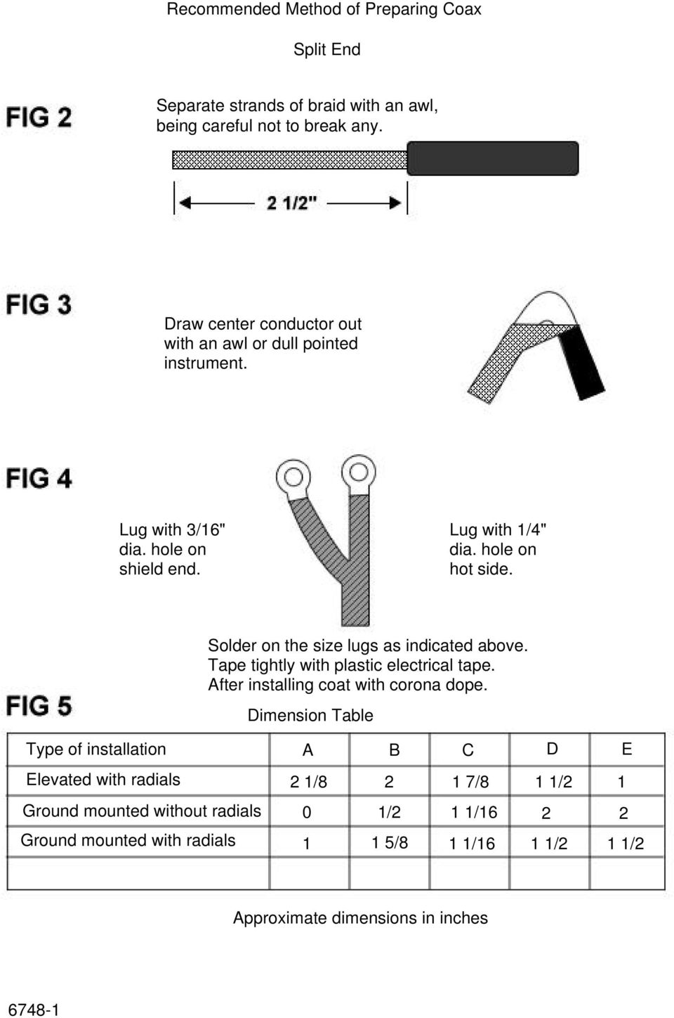
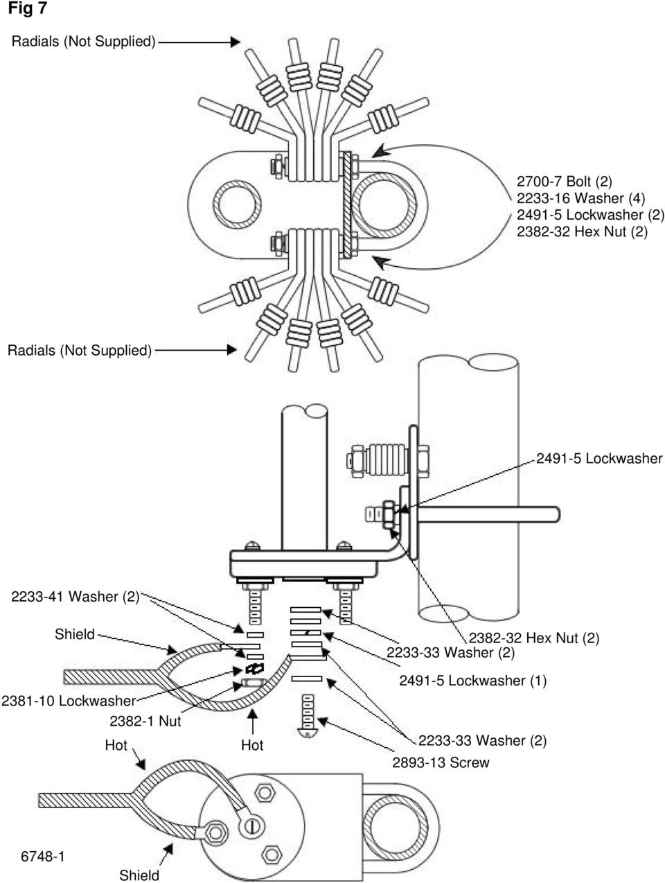
1 Installation Instructions Hustler 6-BTV Trap Vertical ASSEMBLY 1. Check the package contents against the parts list on page WARNING. Installation of this product near power lines is dangerous. For your safety, read the enclosed warnings and follow the installation directions. 3. Prepare split lead on coax in accordance with figures 2 and 3. RG-8/U coax is recommended. (See decoupling information, page 12). 4. Install lugs on coax as shown in figure 4 and weatherproof with electrical tape. 5. Install coax feedline and radials (if needed) as shown in figure 7. Coax length is not critical. 6. After making all connections it is recommended you spray the bracket assembly with a heavy protective coating such as Krylon clear spray coating. 7. Assemble all 1-1/4 in. stainless steel clamps using the 1/4 in.-20 x 3/4 in. screws and 1/4-20 square nuts. 8. Attach the 10-meter trap to the 72 in. tube using one of the clamp assemblies. Set dimension A as indicated in the table in figures 5 and Assemble one of the 20 in. tubes on top of the 10-meter trap using a clamp assembly. Place the 15-meter trap on top of the 20 in. tube and set dimension B (see table figures 5 and 6). Repeat this step with another 20 in. tube and install the 20-meter trap. Set dimension C. 10. Put the 24 in. tube above the 20-meter trap. Place the 30-meter trap on it, using clamp assemblies. Set dimension D (figures 5 and 6). 11. There is no trap for 40 meters. The 40-meter section consists of a 36 in. tube with a threaded stud on the upper end. Install the 40-meter tube on the top of the 30-meter trap. Set dimension E (figures 5 and 6). 12. Screw on the 75/80-meter resonator at the top of the 40-meter tube and adjust the tip rod in accordance with figure 8. NOTE: The Hustler RM-75S and RM-80S resonators are the same. Tip rod length is the only difference. 13. Place the antenna on the bracket assembly and set dimension A, using the last clamp assembly.

2 PACKAGE CONTENTS Part Number Description Qty Tube 1-1/4 in. x 72 in Tube 1-1/4 in. x Tube 1-1/4 in. x Meter Trap Assembly Meter Trap Assembly Meter Trap Assembly Meter Trap Assembly Bracket Assembly Resonator Body Tube and Top Plug Assembly S Tip Rod and Marker Assembly Hardware Kit 1 IN PLASTIC BAG Part Number Description Qty Washer 1/2 in. O.D. x 3/16 in. I.D Hex Nut 1/4 in.-20 x 7/32 in. Thick Lock washer 1/4 in. Split U-Bolts Clamps, Tube SS Nut, Hex SS Terminal Lug 1/4 in. Hole Terminal Lug #10 Hole Danger Label Washer 5/8 in. O.D. x 1/4 in. I.D Hex Nut 1/4-20 x 7/32 in. Thick Lock washer _ in. Split Hex Head Bolt 1/4-20 x 1-1/2 in Lock washer, Ext. #10 SS 1

3

4
5

6
7 TIP ROD LENGTHS FOR 75 OR 80 METER RESONATORS USED WITH 6-BTV Tip rod length measured from top of tip ball down to top of clutch locking nut as illustrated. NOTE: All resonators are supplied with top rod lengths for mobile operation. With the 6-BTV, a shorter length is required, therefore, remove the tip rod from the resonator and grind off the necessary amount from the end that inserts in the resonator. Before cutting, ascertain the approximate rod length from the chart plus four inches for insertion in the upper tube section of the resonator. Dimensions indicated are approximate. FREQUENCY (KHz) RM-75S RM-75 RM-80S RM in. 21-1/4 in /8 in. 22 in in. 22-1/2 in /2 in. 23-3/4 in /8 in. 24-3/4 in /8 in. 26 in /2 in. 26-3/4 in. (Novice Band) (Novice Band) /4 in. 27-3/4 in in. 29-1/4 in /8 in. 31 in in. 33 in /8 in. 34-3/4 in. The above dimensions are exposed lengths of tip rod.

8 INSTALLATION There are two mounting choices. 1. Ground Mount In most areas with normal soil moisture, the 6-BTV can be ground mounted without a radial system. To ground mount your antenna, use a 4 foot metal pipe or mast of 1-1/4 in. O.D. Drive it into the ground, leaving 18 in. protruding. Do not use concrete. Do not dig a hole and bury the mast. It must be driven in. Follow assembly steps 1-6 before mounting the bracket on the mast. The bracket assembly should be placed on the mast so that the feed-point is 4 in. above the ground. After tuning the antenna, compare your A, B, C, D, and E dimensions to the initial dimensions used to assemble the antenna. If your actual dimensions (after tuning) are shorter than the initial dimensions, your ground plane is better than average. If, on the other hand, your actual dimensions are longer, your ground plane is poorer. If this is the case, radials are suggested. Consult page 9 for radial length and configuration. The radials should be buried 2-3 inches underground. 2. Elevated Mount Elevated mounts provide height which, in turn, will generally provide better reception and transmission. Radials are necessary on elevated installations. The ideal droop angle is 45 degrees. A droop angle of 10 degrees to 60 degrees is acceptable. Plan the height of the mount to allow the best droop angle. Consult page 9 for radial information. When installing the radials avoid running them parallel (within 5 feet) to large masses of metal such as chain link fences, metal buildings, etc. The 6-BTV can be mounted on a tower, a heavy duty chimney strap, wooden or metal pole, or other suitable support structure. CAUTION: Mounting the 6-BTV on towers, tripods, or large mast pipes, approximately a quarter wave length, can often provide an upset to the counterpoise created by the radial system, and act as a vertical dipole instead of the desired ground plane. To correct this problem, the radial system must be RF isolated from the mounting structure. This may be done by using a nonconductive mounting mast, such as heavy wall fiberglass tube or fiberglass rod or by sliding a split piece of PVC pipe over the metal mast. The coax or mounting bracket should not be directly grounded. In either mount configuration the 6-BTV must be guyed. Attach the guys above the 20 meter trap.

9 RADIALS Radials should be made from insulated wire of #14 gauge or larger. Insulating the bare ends of wire on the outer end of the radial. A minimum of 2 radials per band is required. Radial lengths are as follows: 10 meters 8' 4" 15 meters 11' 4" 20 meters 16' 4" 30 meters 23' 4" 40 meters 32' 4" 75/80 meters 64' 4"

10 TUNING FOR ALL CHOICES: The dimensions given in the Table are approximate and will vary, depending on environment. To check antenna tuning, use a sensitive SWR bridge. (DO NOT USE A FIELD STRENGTH METER.) Using only sufficient power to obtain a full scale reading, check and record the SWR at the high, center and low edge of the bands. If the SWR reading is lowest at the high end, lengthen the related section of the antenna; if it is lowest at the low end, shorten this antenna section. Always attempt to get the very lowest SWR reading in the center of the band. Tuning in this manner will permit operation in both the phone and CW portions with a low SWR. If you favor one end of the band or the other, you can retune the antenna to provide the lowest SWR in that portion, if desired. In the process of tuning the antenna, it is mandatory that you always start with 10 meters and work your way up the antenna. Tune 10 first, then 15, 20, 30, 40 and 75/80 meters last. Any adjustment made on 10 will affect the other bands. Any adjustment made on 15 will affect 20, 30 and 40. By the same token, any adjustment on 20 will affect 30 and 40. Adjustment of the individual bands is as follows: 10 meters, adjust Dimension A; 15 meters, adjust Dimension B; 20 meters, adjust Dimension C; 30 meters, adjust Dimension D and 40 meters, adjust Dimension E. It is not necessary to remove the bracket each time to adjust the antenna. It is only necessary to remove the antenna from the bracket. (If the desired SWR cannot be achieved, it is probably because of an insufficient counterpoise system or poor soil conditions.) Follow the same tuning procedure for 75/80 meters, adjusting the tip rod of the resonator by loosening the nut and moving the tip rod. The sleeve on the tip rod can be moved to mark the correct tuning position. New-Tronics Antenna Corp. One Newtronics Place Mineral Wells, TX

11 GENERAL HINTS If you are unable to achieve a low VSWR: Be certain the antenna is not within 15 feet of metallic objects or 10 feet of non-metallic objects. The decoupling coil on page 12 should be used. This is especially recommended if TVI is present. If your antenna is elevated, with radials, be certain the mounting bracket is insulated from the mounting mast. The RF ground created by the radial system should not be electrically connected to earth or DC, ground. If you are using radials, be certain they don't run parallel to large metallic objects such as fences. Also avoid metallic objects near the ends of the radials. The ends of the radials should be insulated. Do not use ground rods or ground stakes. They may detune the antenna. Never bunch radials together. They must be evenly spaced around 360 degrees. Do not attempt to tune the antenna by changing coax length. Changing coax length may make the VSWR appear better, but will not change the antenna or its performance. Antenna tuners are not recommended. Use of a tuner treats the symptom (poor VSWR) but does not correct the problem of a poorly tuned antenna. The antenna must be tuned properly to radiate efficiently. Ground mounted antennas should be on a 4 ft. mast only. Masts of other lengths may resonant at an amateur frequency or a multiple thereof, detuning the antenna. SPECIAL APPLICATIONS The 6-BTV can be mounted on metal buildings, RV's or other structures, utilizing the metal for a ground plane. The feed point of the antenna should be 4" above the metal ground plane. Use the ground mount dimensions for the initial setup. The 6-BTV is designed for the average ground plane. As the ground plane increases, the antenna becomes shorter. For this reason it may be necessary to trim some sections in order to reach resonance. Since your coax shield is connected to where a radial would connect, it too will act as a radial. This is not desirable since this imposes additional currents which will detract from the antennas low V.S.W.R. at the rig end of your coax.

12 To prevent this from occurring, form at the bottom of the antenna or within eight feet of the base, a coil in your coax. By wrapping your coax in a single layer fashion, ten times around a 6" diameter form, you will form an R.F. choke in the braid which will isolate these additional currents from your coax. Since your coax (the shield) is in the R.F. near field of your antenna, it will act as a collector of R.F. energy (an antenna). This too is not desirable since this can impose similar additional currents which will register as a higher V.S.W.R. at the rig. To prevent this, form the same type coil as before at/or within eight feet of your rig. These coils will NOT impede the R.F. energy contained inside the coax from flowing. It only acts as high impedance to the undesirable additional currents on the outside braid of your coax. After having installed these coils, you may need to retune the antenna. If you still have a high V.S.W.R., perhaps tuned radials are needed.

13 NEWTRONICS ANTENNA CORP. Newtronics Antenna Corp. warrants its products to be free of defects in material and workmanship and extends this warranty under intended use and normal service conditions to the original owner for a period of one year from the date of purchase. This warranty does not apply to any product that has been repaired or altered in any manner and is void for any damage due to accident, neglect, unreasonable use, improper installation of any other cause not arising out of defects in material of workmanship. The obligations of Newtronics Antenna Corp. are limited to repairing or replacing, at its option, any product or part that is returned to the factory, all transportation charges prepaid, accompanied by proof of purchase and which examination reveals to have been defective within the warranty period stated above. Newtronics Antenna Corp. does not assume nor is any person authorized to assume for it, any obligations other than that herein stated. Any implied warranties, including but not limited to fitness for a particular purpose, are limited in duration for the above one year period. Newtronics Antenna Corp. shall not be liable under this warranty, or any implied warranty, for loss of use of the product or for other consequential loss or damage incurred by the purchaser. Some states do not allow the exclusion of limitation of implied warranties of consequential damages and so the above exclusions of limitations may not apply. This warranty gives you special legal rights and you may have other rights that vary from state to state. One Newtronics Place Mineral Wells, Texas

INSTALLATION INSTRUCTIONS HUSTLER 4-BTV, 5-BTV TRAP VERTICAL WARNING INSTALLATION OF THIS PRODUCT NEAR POWER LINES IS DANGEROUS
 INSTALLATION INSTRUCTIONS HUSTLER 4-BTV, 5-BTV TRAP VERTICAL WARNING INSTALLATION OF THIS PRODUCT NEAR POWER LINES IS DANGEROUS FOR YOUR SAFETY, FOLLOW THE INSTALLATION DIRECTIONS GENERAL DESCRIPTION:
VEC-896 Vertical Antenna
 VEC-896 Vertical Antenna INTRODUCTION The basic 40 meter quarter wave vertical antenna is 33' tall and requires a reasonably good ground or counterpoise system to function properly. The usual way to eliminate
EH-20 20m antenna. By VE3RGW
 EH-20 20m antenna By VE3RGW Equivalent circuit of EH-20 (prototype 2A) antenna system. Upper cylinder Lower cylinder Ground Counter pose Phasing coil Impedance transformer and tune circuit Tune coil Feed
SAFETY NOTICE WARNING! POWER LINES CAN KILL YOU
 PG1 SAFETY NOTICE WARNING! POWER LINES CAN KILL YOU DO NOT ERECT THIS ANTENNA NEAR ANY OVERHEAD WIRES, UNDER ANY CIRCUMSTANCES. READ AND FOLLOW THESE INSTRUCTIONS CAREFULLY 1) Do not erect this antenna
4-BTV, 5-BTV, 6-BTV Multiband HF Vertical Antennas. New Assembly and High Performance Installation Instructions - 1 -
 4-BTV, 5-BTV, 6-BTV Multiband HF Vertical Antennas New Assembly and High Performance Installation Instructions DXE-BTV-INSTALL GUIDE - Rev 0 Cost: $5.00 To be certain to get optimum performance from this
M2 Antenna Systems, Inc. Model No: KT34M2
 M2 Antenna Systems, Inc. Model No: KT34M2 10m f, MHz G, dbi F/B, db 28.0 7.3 18 28.2 7.3 23 28.4 7.4 25 28.6 7.5 24 29.2 7.6 20 15m f, MHz G, dbi F/B, db 21.0 6.9 19 21.1 6.9 22 21.2 7.0 24 21.3 7.0 24
2007 MFJ ENTERPRISES, INC.
 80/40/20 Meter Rotatable Dipole Model MFJ-1785 INSTRUCTION MANUAL CAUTION: Read All Instructions Before Operating Equipment MFJ ENTERPRISES, INC. 300 Industrial Park Road Starkville, MS 39759 USA Tel:
HMS Hairpin Matching Systems
 HMS Hairpin Matching Systems DXE-HMS-1P, DXE-HMS-2P, DXE-HMS-4P DXE-HMS-INS-Rev 1b For Use with 1-1/2 Inch through 3 Inch Booms Shown with optional boom, elements and Element Bracket with hardware DX Engineering
Owners Manual For The PackTenna Mini
 Owners Manual For The PackTenna Mini By Nick Garner N3WG and George Zafiropoulos KJ6VU Quickstart With The 9:1 Random Wire Version You can identify this version because it has a yellow shrink wrap on the
EZ-48-3AB-125-35 Weather Station Mounting Tripod and Mast
 EZ-48-3AB-125-35 Weather Station Mounting Tripod and Mast EZ-125-35M 35 Mast Extension (Optional) EZ-125-SK Stake Kit (Optional) EZ-46-3 Tar Pad Kit (Optional) EZ-GWA Guy Wire Kit (Optional) Ambient Weather
Installation Instructions GOOSENECK MOUNTING KIT Chevrolet/GMC 1500/2500/3500 All except 4-door Crew-Cab
 GOOSENECK MOUNTING KIT Equipment Required: Fastener Kit: F Wrenches: 3/4, 7/8, 15/16 Drill Bits: 1/4 Other Tools: Drill WARNING: Under no circumstances do we recommend exceeding the towing vehicle manufacturers
Installation Instructions: (Part # SB76880) XRC Armor Front Fender Kit
 XRC Armor Front Fender Kit") WARNING: Check with Local and State laws before installing this accessory! NOTE: Carefully read entire instructions thoroughly before attempting to install this part. Parts Included: Qty Parts Included:
WARNING: Check with Local and State laws before installing this accessory! NOTE: Carefully read entire instructions thoroughly before attempting to install this part. Parts Included: Qty Parts Included:
Weekend Antennas No. 1 A Bobtail Curtain for 2m
 Weekend Antennas No. 1 A Bobtail Curtain for 2m Welcome to the first installment of my new column, which I hope will become a regular feature in Radio ZS. Each installment will present a practical and
ANTENNA PARTS CATALOG
 ANTENNA PARTS CATALOG Maco Antennas 302 S. East St. Mt. Carroll, IL 61053 www.macoantennas.net 815-244-3500 www.antennapartsoutlet.com SCREWS / BOLTS PART SIZE LENGTH DESCRIPTION PRICE S21 10-24 1/2" Machine
Model S9v. 18 Mk II Multiband Vertical Antenna Installation Guide
 Model S9v 18 Mk II Multiband Vertical Antenna Installation Guide WARNING: INSTALLATION OF THIS PRODUCT NEAR POWERLINES IS DANGEROUS. FOR YOUR SAFETY, FOLLOW THE INSTALLATION DIRECTIONS. INTRODUCTION Thank
2 Meter Half-Wave J-Pole Antenna From 450 Ohm Ladder Line
 2 Meter Half-Wave J-Pole Antenna From 450 Ohm Ladder Line Photos: Copyright 2007 David Jordan WA3GIN. All rights reserved. This is a good rainy day antenna project for those of you who would like to home
BUILT-IN DISHWASHER INSTALLATION INSTRUCTIONS
 BUILT-IN DISHWASHER INSTALLATION INSTRUCTIONS PLEASE READ COMPLETE INSTRUCTIONS BEFORE YOU BEGIN LEAVE INSTALLATION INSTRUCTIONS AND USER'S GUIDE WITH OWNER ALL ELECTRIC WIRING AND PLUMBING MUST BE DONE
Triple Threat 3-in-1 Game Table 3 IN 1 GAME TABLE
 NG0M Triple Threat 3-in- Game Table 3 IN GAME TABLE Thank 3 in Y Game Table Thank you for your purchase of our product. We work around the clock and around the globe to ensure that our products maintain
ATS Overhead Table Shelf System INSTRUCTION MANUAL
 ATS Overhead Table Shelf System INSTRUCTION MANUAL ATS Overhead Table Shelf System Instruction Manual Warranty Newport Corporation warrants this product to be free of defects in material and workmanship
In-Ground Basketball System Owners Manual
 In-Ground Basketball System Owners Manual Customer Service Center N53 W4700 South Corporate Circle Sussex, WI 53089 U.S.A. Write Model Number From Box Here: WARNING! 3 Capable Adults REQUIRED TOOLS AND
RZ Guardrail System Installation Manual
 TM RZ Guardrail System Installation Manual RZ Guardrail System Compliance is based on OSHA standards: (Standards - 29 CFR) 1910.23 (e) and (Standards - 29 CFR) 1926.502 (b) Failure to read, understand
Broadband Terminated Vee Beam Wire Antenna
 Broadband Terminated Vee Beam Wire Antenna TEN-TEC Model 3402 and 3403 1.8-54 or 3.5-54 MHz. THROW AWAY YOUR ANTENNA TUNER! Models 3402 and 3403 are broadband terminated vee beam wire antennas. These broadband
Wind Direction Smart Sensor (S-WDA-M003)
") (S-WDA-M003) The Wind Direction smart sensor is designed to work with HOBO Stations. The smart sensor has a plug-in modular connector that allows it to be added easily to a HOBO Station. All sensor parameters
(S-WDA-M003) The Wind Direction smart sensor is designed to work with HOBO Stations. The smart sensor has a plug-in modular connector that allows it to be added easily to a HOBO Station. All sensor parameters
READ CAREFULLY - FAILURE TO FOLLOW INSTRUCTIONS AND SAFETY RULES MAY RESULT IN SERIOUS INJURY
 Owner s Manual LSP16H LS3001 LS3002H LS3003 LSP21H LS3101 LS3102H LS3103 LSP24H LS3201 LS3102H LS3103 LSP28H LS3301 LS3302H LS3303 mainframe bundle H-unit bundle accessory box mainframe bundle H-unit bundle
CUSHCRAFT R5 (10/12/15/17/20 m) POWER PRACTICAL TESTS INSULATOR
 POWER PRACTICAL TESTS INSULATOR") onhr5engres Page 1 of 6 Cushcraft R5 ½ λ Vertical Maintenance and Repair CUSHCRAFT R5 (10/12/15/17/20 m) Cushcraft have made many vertical antennas; R4, R5, R6, R6000, R7, R7000, R8 etc. All are ½ wave
onhr5engres Page 1 of 6 Cushcraft R5 ½ λ Vertical Maintenance and Repair CUSHCRAFT R5 (10/12/15/17/20 m) Cushcraft have made many vertical antennas; R4, R5, R6, R6000, R7, R7000, R8 etc. All are ½ wave
Hendricks 40m 15m SOTA EFHW Tuner
 Hendricks 40m 15m SOTA EFHW Tuner First, familiarize yourself with the parts and check for all the components. Parts Inventory 1 - Tayloe SWR Indicator kit 1 - T50-6 core (yellow), T94-2 (red) core not
HDTV. Amplified Indoor Outdoor Antenna. indoor outdoor. 10 db Amplification. Paintable. Versatile TERRESTRIAL VHF UHF
 Amplified Indoor Outdoor Antenna VHF UHF 10 db Amplification fixed 10 db amplification for improved reception of weak signals Paintable customize your antenna color to match your interior or exterior décor
CP2 Buried Cable Pedestal Initial & Rehab Installation Instructions
 Printing 3 March 2008 CP2 Buried Cable Pedestal Initial & Rehab Installation Instructions This instruction is intended for CP2 cable pedestal installations and replacements. The following tools will be
Model S9v43. 43 Multiband Vertical Antenna Installation Guide
 Model S9v43 43 Multiband Vertical Antenna Installation Guide. WARNING: INSTALLATION OF THIS PRODUCT NEAR POWERLINES IS DANGEROUS. FOR YOUR SAFETY, FOLLOW THE INSTALLATION DIRECTIONS. INTRODUCTION Thank
Table of Contents WARNING SYMBOLS AND DEFINITIONS
 Table of Contents SAFETY INSTALLATION OPERATION MAINTENANCE Safety... 2 Specifications... 4 Installation... 5 Operation... 8 WARNING SYMBOLS AND DEFINITIONS Maintenance... 9 Parts List and Assembly Diagram...
Rating when used as a weight carrying hitch without spring bars:
 BOLT-TOGETHER WEIGHT DISTRIBUTING HITCH SYSTEM Rating when used as a weight distributing hitch with spring bars: Part Number 48051 4805 48053 48054 Max Tongue Weight 550 Ibs. 750 Ibs. 1000 Ibs. 1400 lbs.
Mounting Tripod Kit Installation Manual
 Mounting Tripod Kit Installation Manual For use with Davis s wireless and cabled Vantage Pro2 weather stations, the Mounting Tripod simplifies installation. The tripod supports the Integrated Sensor Suite
Toroidal Conductivity Sensor
 Instruction Sheet PN 51A-/rev.C June 2012 Toroidal Conductivity Sensor For additional information, please visit our website at www.emersonprocess.com/rosemountanalytical.com SPECIFICATIONS Wetted Materials:
Calvert USA, Inc. Attic Stairs
 Calvert USA, Inc. Attic Stairs Instructions for installation of vertical opening access stairs Model numbers: 7035 through 7047 Calvert USA, Inc., P.O. Box 841, Solomons, MD 20688, Tel. (410) 286-1430,
Portable HF Antennas. Presented to the Stamford Amateur Radio Association. by Jon Perelstein. Copyright 2010 Jon Perelstein 1
 Portable HF Antennas Presented to the Stamford Amateur Radio Association by Jon Perelstein Copyright 2010 Jon Perelstein 1 For purposes of this presentation, a portable HF antenna is An antenna that doesn't
Solar Power Systems Models: PVS220W-24 and PVS220W-48 Installation Manual
 Solar Power Systems Models: PVS220W-24 and PVS220W-48 Installation Manual 255379 Rev. D0 1015 Printed in U.S.A. Copyright 2015 Federal Signal Corporation Limited Warranty The Alerting and Notification
I-Line. Accessories. Essential cable installation products for corrugated, smooth wall, and braided cables
 I-Line TM Essential cable installation products for corrugated, smooth wall, and braided cables Installation Coaxial cable installation components for corrugated, smooth wall and braided cables Proven
By SP Partners, LLC. www.rainbowatticstair.com INSTALLATION GUIDE. Prestige
 By SP Partners, LLC www.rainbowatticstair.com INSTALLATION GUIDE Prestige IMPORTANT READ THIS FIRST Inspect stair for any damage prior to installation. Stair is NOT to be installed while home is under
PLEASE - Read this entire booklet and study the diagrams before building a Quad, it can save you unwarranted frustrations!
 VHF/UHF Quad Antenna The information in this article has come from many amateur sources, the most notable was from WA6TEY (sk 1985) Ray Frost, who was a pioneer of VHF Quad designs and one of the best
Hydraulic Punch Driver Kit
 Hydraulic Punch Driver Kit Item 96718 Instructions and precautions Visit our website at: http://www.harborfreight.com Read this material before using this product. Failure to do so can result in serious
INSTALLATION INSTRUCTIONS PART NUMBER:
 Equipped with AEM Dryflow Filter No Oil Required! INSTALLATION INSTRUCTIONS PART NUMBER: 21-475B (Blue Finish) 21-475C (Gun Metal Grey Finish) 21-475P (Vacuum Metalized Chrome-VMC) 21-475R (Red Finish)
Multi-Pitch Pitching Machine USER MANUAL
 Multi-Pitch Pitching Machine USER MANUAL TABLE OF CONTENTS Thank you for purchasing the Cimarron Multi-Pitch Pitching Machine. The Cimarron Multi-Pitch Pitching Machine is a high performance pitching machine
Installation Guide. WSD-100 Wind Speed and Direction Sensor For XR5 Data Loggers. February, 2011
 WSD-100 Wind Speed and Direction Sensor For XR5 Data Loggers Installation Guide February, 2011 Pace Scientific Inc www.pace-sci.com Tel: 704-799-0688 [email protected] 1 Disclaimer The following warranty
Cisco Aironet 2.4-GHz MIMO Wall-Mounted Omnidirectional Antenna (AIR-ANT2440NV-R)
") Cisco Aironet 2.4-GHz MIMO Wall-Mounted Omnidirectional Antenna (AIR-ANT2440NV-R) This document outlines the specifications for the Cisco Aironet 2.4-GHz MIMO Wall-Mounted Omnidirectional Antenna (AIR-ANT2440NV-R)
Cisco Aironet 2.4-GHz MIMO Wall-Mounted Omnidirectional Antenna (AIR-ANT2440NV-R) This document outlines the specifications for the Cisco Aironet 2.4-GHz MIMO Wall-Mounted Omnidirectional Antenna (AIR-ANT2440NV-R)
40m-10m DELTA LOOP ANTENNA - GU3WHN
 This simple broad band antenna is easy to build, has gain similar to that of a dipole and is tolerant of nearby objects. It can be erected in almost any configuration provided the wires are well separated
REPAIR PARTS MANUAL MODEL NO. PR160Y21RDP (MFG. ID. NO. 96142004500) Rotary Lawn Mower
 Rotary Lawn Mower") REPAIR PARTS MANUAL MODEL NO. PR160Y21RDP (MFG. ID. NO. 96142004500) Rotary Lawn Mower For Parts and Service, contact our authorized distributor: call 1-800-849-1297 For Technical Assistance: call 1-800-829-5886
REPAIR PARTS MANUAL MODEL NO. PR160Y21RDP (MFG. ID. NO. 96142004500) Rotary Lawn Mower For Parts and Service, contact our authorized distributor: call 1-800-849-1297 For Technical Assistance: call 1-800-829-5886
Security Cameras, CATV, GPS & Satellite Protection. White Paper
 Security Cameras, CATV, GPS & Satellite Protection White Paper Security Cameras, CATV, GPS & Satellite Protection Surge Protection Solutions for PTC 1 Security Cameras, CATV, GPS & Satellite Protection
Speed-Mat Rectangle Cutter
 Speed-Mat Rectangle Cutter 1 Honeycomb baseboard. 2 Left hold down. 14 3 Bottom hold down. 4 4 Left / right rule. 8 5 8 5 Left / right rule pointer. 1 6 Top / bottom rule. 7 Top / bottom rule pointer.
Operating Instructions
 Operating Instructions Series L 000 Cord Reels Model Numbers: L 000 L 0 0 L 0 B L 0 X L 00 L A X L 0 L 0 0 L 00 L 0 L 0 B L 0 0 X L 00 L 0 A L 0 X IMPORTANT Read this manual carefully before installing,
WARNING TO END USER, INSTALLER AND SELLER OF THIS PART!
 WARNING TO END USER, INSTALLER AND SELLER OF THIS PART! By installing this part you are accepting full responsibility and liability for proper wheel and tire fitment after installation. It is the installer
My Loop Antenna. Stephen E. Sussman-Fort, Ph.D. AB2EW. [email protected]
 Stephen E. Sussman-Fort, Ph.D. AB2EW [email protected] Outline Brief History Characteristics of Small Loop Antennas for HF My Loop for 40m 15m Receive/Transmit Properties of Elect.-Small Loops Loop
2178-S Fiber Optic Splice Case
 2178-S Fiber Optic Splice Case Instructions March 1998 34-7041-6288-1-B 1 2 Table of Contents 3M 2178-S Splice Case Description... 4 1.0 General...4 2.0 Specifications...4 3.0 Kit Contents...5 3M 2178-S
ANTENNA SYSTEMS. 1.8m Offset TxRx Antenna INSTALLATION & ASSEMBLY INSTRUCTIONS
 ANTENNA SYSTEMS 1.8m Offset TxRx Antenna INSTALLATION & ASSEMBLY INSTRUCTIONS LIMITED TWELVE (12) MONTH WARRANTY This PATRIOT ANTENNA equipment is warranted to be free from defects in material and workmanship
Advantium 2 Plus Alarm
 ADI 9510-B Advantium 2 Plus Alarm INSTALLATION AND OPERATING INSTRUCTIONS Carefully Read These Instructions Before Operating Carefully Read These Controls Corporation of America 1501 Harpers Road Virginia
JP Tribander Owner Manual
 JP Tribander Owner Manual JP-Tribander Technical overview JP-Tribander is effective tribander beam for 20m, 15m and 10meters with full size elements without traps. Antenna is designed using latest computer
Installation Instructions For Slider Casement Air Conditioners
 Installation Instructions For Slider Casement Air Conditioners NOTE: These instructions describe installation in a typical wood framed window with a wood SLIDE-BY sash, or installation in a metal CASEMENT
40 Meter Mini-MOXON Beam Antenna. Designed, built, and presented by: Al Koblinski W7XA
 40 Meter Mini-MOXON Beam Antenna Designed, built, and presented by: Al Koblinski W7XA Design goals Some forward gain Good directivity (high F/B and F/S ratios) Relatively small size Good Bandwidth (min.
Please Do Not Return This Product To The Store!
 O W N E R ' S MODEL NO. M A N U A L B0F B0W CV60 BASKETBALL SYSTEM. Read this manual carefully before starting assembly. Read each step completely before beginning each step.. Some smaller parts may be
LDG RBA-4:1Balun LDG RBA-1:1Balun
 LDG RBA-4:1Balun LDG RBA-1:1Balun Table of Contents Features 1 Specifications 1 Preparation 2 An important word about power levels: 2 Installation 2 Care and Maintenance 6 Technical Support 6 Warranty
Please Do Not Return This Product to the Store!
 MODEL NO. B400W GS60 BASKETBALL SYSTEM O W N E R ' S M A N U A L 1. Read this manual carefully before starting assembly. Read each step completely before beginning each step.. Some smaller parts may be
Installation Instructions HighRock 4x4 TM
 Installation Instructions HighRock 4x4 TM Slider Step Vehicle Application: Jeep YJ and TJ Wrangler 1986 2006 Part Number: 49312 www.bestop.com - We re here to help! Visit our web site and click on Ask
WiMo Antennen und Elektronik GmbH Am Gäxwald 14, D-76863 Herxheim Tel. (07276) 96680 FAX 9668-11
 96680 FAX 9668-11") The I-PRO Traveller part no. 11440 Thank you for your purchase, please take your time to digest some of the important building tips and the essential matching/adjustment techniques. You will need 8m of
The I-PRO Traveller part no. 11440 Thank you for your purchase, please take your time to digest some of the important building tips and the essential matching/adjustment techniques. You will need 8m of
Assembly Instructions for the InteliTrack 3000 Rail Tracking System
 Assembly Instructions for the InteliTrack 3000 Rail Tracking System InteliTrack is a trademark of Sedona Solar Technology. Sedona Solar Technology 16 April 2013 1 1. Before you begin WARNING Safety equipment
There are at least six ways to go about loading a short vertical monopole.
 With a mobile installation and most base locations, the HF seems to pose problems especially using the top band. 160 meters is also known as the top band. It is the only frequency group in the MF band
HF OPERATORS SMALL HF ANTENNAS - - - - - - - - - - - Rev 1. John White VA7JW
 HF OPERATORS SMALL HF ANTENNAS Rev 1 by John White VA7JW NSARC HF Operators 1 Antenna Problems Big or Small always problems. Affects all - Single family, apartments, condo s, high rises, etc The Small
USE &CARE GUIDE. Remote Faucet Pump System. See Important Safeguards on page 2
 Remote Faucet Pump System USE &CARE GUIDE See Important Safeguards on page 2 An exclamation point within an equilateral triangle is intended to alert user to the presence of important operating and maintenance
SECTION 22 LIGHTNING PROTECTION SYSTEM
 SECTION 22 LIGHTNING PROTECTION SYSTEM 22.01 SCOPE: A. These Specifications shall form a part of the Contract Documents and shall govern construction work for all buildings to be built or modified for
ELECTRIC KNIFE SHARPENER
 PRODUCT MANUAL- M109 MODEL 401 ELECTRIC KNIFE SHARPENER Please read thoroughly before operation and keep for future reference Model 401 Knife Sharpener Specifications Model No. #401 Power Requirements
This mount uses concrete parking bumpers and a Davis tripod to create a mounting solution for nonpenetrable
 NON-PENETRATING FLAT ROOF MOUNT Application Note 18 For Any Davis Weather Station Installed on a Mounting Tripod Introduction This application note describes various mounting solutions for non-penetrable
LOW-VOLTAGE TRANSFORMER QUICK START GUIDE PLANNING GUIDE INSTALLATION GUIDE
 LOW-VOLTAGE TRANSFORMER QUICK START GUIDE PLANNING GUIDE INSTALLATION GUIDE Applies to Models: 75W, 150W, 300W, 600W, 900W, 1200W ATTENTION: Please read this guide carefully to ensure safe and efficient
Here are the details with pictures of the items for sale as listed below. Please Scroll Down.
 Here are the details with pictures of the items for sale as listed below. Please Scroll Down. Further Items are also available - for further list please phone or e-mail Phone Ivan 073 528 4950 or 021 439
OPERATING INSTRUCTIONS AND PARTS LIST FOR U075075 U100058 UNDERGROUND HOSE REELS
 OPERATING INSTRUCTIONS AND PARTS LIST FOR U075075 U0005 FORM NO.: 3-00 REV: RAIN BIRD CORPORATION ONE REELCRAFT CENTER COLUMBIA CITY, IN 675 (00) -33 / (60) - FAX: (60) -605 U0005 MODEL NUMBER SIGNIFICANCE
Cheap Antennas for the AMSAT LEO's Kent Britain -- WA5VJB
 Cheap Antennas for the AMSAT LEO's Kent Britain -- WA5VJB Cheap LEO Antenna Drew, KO4MA, using the Cheap LEO antenna during a Dayton AMSAT LEO Demonstration Hand held dual band antennas are popular for
Installation Instructions
 page 1 of 7 Description These feeds are designed for installation in shielded standard types of parabolic antennas. The feed is designed for positive metal-to-metal contact between the feed and the reflector,
Basic Wire Antennas. Part II: Loops and Verticals
 Basic Wire Antennas Part II: Loops and Verticals A loop antenna is composed of a single loop of wire, greater than a half wavelength long. The loop does not have to be any particular shape. RF power can
OWNER S MANUAL Table Tennis Table Patent Pending
 OWNER S MANUAL Table Tennis Table Patent Pending Be sure to write your model number and serial number here for future reference. You can find these numbers printed on the bottom of the table. MODEL # T8179
Equipped with AEM Dryflow Filter No Oil Required! INSTALLATION INSTRUCTIONS PART NUMBER 21-754DS. 2012-2015 BMW 335i 3.0L
 Equipped with AEM Dryflow Filter No Oil Required! INSTALLATION INSTRUCTIONS PART NUMBER 21-754DS 2012-2015 BMW 335i 3.0L 1 ITEM NO. PART NUMBER DESCRIPTION QTY. 1 21-2057DK AIR FILTER 1 2 9-0442 TUBE;
WINEGARD MOTORIZED SENSAR ANTENNA Models MA1055W & MA1055G MADE IN U.S.A. U.S. Patents D500,496 and 7,358,909 INSTALLATION MANUAL
 WINEGARD MOTORIZED SENSAR ANTENNA Models MA1055W & MA1055G MADE IN U.S.A. U.S. Patents D500,496 and 7,358,909 INSTALLATION MANUAL CAUTION: This system is not for use with antenna in raised position while
MSA Saddle Machine Parts & Operating Manual
 Machine Model Serial# Register product online @ www.mathey.com PO Box 472110 Tulsa, OK 74147 USA Toll Free: 800-725-7311 918-447-1288 office 918-447-0188 fax www.mathey.com MSA
Eric Six Heath Consultants Incorporated
 Eric Six Heath Consultants Incorporated 9030 Monroe Road Houston, TX 77061 www.heathus.com The contents of this manual are proprietary to Heath Consultants (HEATH). Reproduction in whole or in part of
RAIN COLLECTOR S HELF MANUAL
 RAIN COLLECTOR S HELF MANUAL The Rain Collector Shelf provides a good mounting support for your Rain Collector II. The Rain Collector Shelf is designed to be attached to Davis Sensor Mounting Arm, and
ZS6BKW vs G5RV. Antenna Patterns/SWR at 40 ft Center height, 27 ft end height ~148 Degree Included Angle
 ZS6BKW vs G5RV Antenna Patterns/SWR at 40 ft Center height, 27 ft end height ~148 Degree Included Angle Compiled By: Larry James LeBlanc 2010 For the AARA Ham Radio Club Note: All graphs computed using
TRACTOR QUICK HITCH CATEGORY I
 TRACTOR QUICK HITCH CATEGORY I Assembly, Operation & Parts Manual January 2005 Form: Quickhitch.PM7 SAFETY INFORMATION To avoid accident or injury, do not allow anyone to operate this equipment without
WARNING: FAILURE TO FOLLOW THESE RULES MAY RESULT IN SERIOUS PERSONAL INJURY CAUTION: INSTALLATION LOCATION:
 Revision Level: 01 Revision Date: 07/07/2011 Please read all instructions carefully to help ensure a correct and SAFE installation of your Second Wind Ultraviolet Germicidal Air Purifier. Failure to do
123 Industrial Loop Road Paynesville, MN 56362 Phone: 1-800-864-1649 www.master-mfg.com MASTER MANUFACTURING MASTER GARDNER
 123 Industrial Loop Road Paynesville, MN 56362 Phone: 1-800-864-1649 www.master-mfg.com MASTER MANUFACTURING MASTER GARDNER Part Number PCD E3 009B MM Rev 1 Nov. 2010 INTRODUCTION The purpose of this manual
MODEL #12006. Introduction
 THE ORIGINAL PECO POWER SPRAYER PECO OWNER S MANUAL MODEL #12006 (Q0080) Revised: 1/8/2014 PECO POWER SPRAYER MODEL #12006 TABLE OF CONTENTS SECTION PAGE SECTION PAGE INTRODUCTION - - - - - - - - - - -
Weatherproof Tournament Table Tennis Table
 Weatherproof Tournament Table Tennis Table Owner s Manual Model Number 7035-590 Absolutely Weatherproof Printed on 100% recycled paper.! Made in Germany Thank you for purchasing our high quality KETTLER
Invisible DX Antenna for the Low Bands
 Invisible DX Antenna for the Low Bands By Heinz-Josef Pick, DK5WL Summary This paper describes a multi-band DX antenna for the 160m-40m amateur radio bands with low visibility but great performance for
Elo Touch Solutions Wall-mounting Kit for the 5501L IDS Touchmonitors
 Installation Manual Elo Touch Solutions Wall-mounting Kit for the 5501L IDS Touchmonitors SW602206 Rev B Table of Contents Chapter 1: Safety Warning... 3 Chapter 2: Kit Contents... 4 Included in Kit...
NONSUCH SPARS Recommended Owner s Maintenance Schedule
 NONSUCH SPARS Recommended Owner s Maintenance Schedule The first Nonsuch masts were designed and produced in 1978 and these prototype spars are standing and functioning today after seven seasons of hard
Small HF Antennas - - -- - - - -- - - ! The Small Space and Big Antenna Dilemma! Constraints
 Small HF Antennas! The Small Space and Big Antenna Dilemma! Constraints " Covenants " Restricted lot size " City Bylaws " Boards of Variance " Strata Rules " Neighbor complaints of unsightly structures
Technician Licensing Class
 Technician Licensing Class Antennas Presented by Amateur Radio Technician Class Element 2 Course Presentation ELEMENT 2 SUB-ELEMENTS (Groupings) About Ham Radio Call Signs Control Mind the Rules Tech Frequencies
Guidelines for Earthquake Bracing Residential Water Heaters
 Guidelines for Earthquake Bracing Residential Water Heaters Department of General Services Division of the State Architect In accordance with the Health and Safety Code Section 19215, the Division of the
Installation Instructions
 Installation Instructions S50-310 (Semi-Circular) S50-311 (Circular) Accu-Zone Infrared Control Conversion Kit for Terrazzo & Stainless Steel Classic Washfountains (Non-sectional) Table of Contents Pre-Installation
Slide the new steering column shaft through the steering column from the driver compartment.
 Slide the new steering column shaft through the steering column from the driver compartment. Push the column shaft through the steering column until the machined end is out past the column lower bushing.
POLE MOUNT SYSTEM EX-3 INSTALLATION
 May 2014 POLE MOUNT SYSTEM EX-3 INSTALLATION The Pole Mount System EX-3 is an easy to install and flexible system designed to allow ONE SYSTEMS loudspeaker systems to be mounted to pole structures. The
Guidelines for Earthquake Bracing of Residential Water Heaters
 Guidelines for Earthquake Bracing of Residential Water Heaters Department of General Services Division of the State Architect 1102 Q Street, Suite 5100 Sacramento, CA 95814 Phone: (916) 324-7099 Fax: (916)