Efficient Pneumatic Conveying Dense Phase vs. Dilute Phase: How Being Accurate is More Cost Effective Than Being Conservative
|
|
|
- Hilda Spencer
- 7 years ago
- Views:
Transcription
1 2013 World of Coal Ash (WOCA) Conference - April 22-25, 2013 in Lexington, KY Efficient Pneumatic Conveying Dense Phase vs. Dilute Phase: How Being Accurate is More Cost Effective Than Being Conservative Kody W. Smajstrla, P.E. LB Industrial Systems, San Antonio TX KEYWORDS: Dense Phase, Dilute Phase, Pneumatic, Conveying, Fly Ash Submitted for consideration in the 2013 World of Coal Ash Conference, April 22-25, INTRODUCTION In the coal combustion products realm there is a growing trend towards requiring dilute phase pneumatic conveying as a rule. The first hurdle to meet with this mindset is to actually define dilute phase. A widely accepted definition available for dilute phase flow is a two phase flow where all of the conveyed particles are carried in suspension [1]. From a practical standpoint this definition is useless as, short of installing sections of transparent pipe, there is no way to verify whether 100% of the conveyed material is being carried in suspension. The next logical step is to determine some measurable properties to serve as the delineation between dense and dilute phase. Commonly gas velocities and pressure drops are selected to serve this purpose. The problem with such a definition is that for it to hold true for a range of materials, the values need to be very conservative. For example, it is not unusual to hear a plant engineer or operator state that a pressure conveying system that operates with air velocities over 3000 ft/min or overall pressure drops of less than about 15 psi is indeed a dilute phase system. The question you should be asking yourself is Is this cost effective? PROBLEM From the viewpoint of a design and supply firm overly conservative design requirements are wonderful. At such elevated airflow rates one needs little to no knowledge of the material. At ft/min one could successfully convey iron powder through a pipeline so fly ash with its characteristic permeability, air retention, and ease of conveying can certainly be moved with little concern [2]. So now I can cut costs by not having to invest in the expertise of my design engineers. To meet the higher velocities I also get to supply much larger blowers than may be necessary; another increase in profit margin. To keep the pressure

2 drop within range at these elevated specified velocities larger pipe is usually necessary. Now I am providing more pounds of steel per foot of conveyance thanks to increased pipe sizes and beefier supports required to keep it all in the air. As pipeline erosion is a function of airflow proportional to the range of velocity squared to velocity cubed, a dramatically increased erosion rate at and near fittings should be expected [3]. Again, as a design and supply firm I see dollar signs. Now I can provide hardened fittings, hardened pipe, and severe service valves. The beauty of these components is, although they will slow the erosion rate, they do not stop the actual damage mechanism. So they WILL wear out and if I can convince the client that they need MY proprietary fittings and valves they will have to come back to me to purchase the replacements. This aspect can be so lucrative that I may be willing to actually sacrifice profit on the initial project just to get my foot in the door and enrich myself as a parts provider. It should be obvious that blindly setting such conservative limits stacks the deck in the design and supply firm s favor. As the customer who is spending hundreds of thousands, if not millions, of dollars on such products shouldn t you be provided with a system that is designed with efficiency and reliability (i.e., your best interest) in mind? STUDY This study examines a recent proposal where the customer requested a system to be designed to a conservative dilute phase specification. The system was designed and quoted per the customer specification; however, an alternative system design was quoted for comparison by the customer applying a hybrid phase approach tailored to the customer s performance requirements. The following paragraphs will describe the system layout, design method, final design differences, and financial differences. Pressure Conveying Overall Pressure Drop Requirement Pressure Conveying Minimum Air Velocity Vacuum Conveying Overall Pressure Drop Requirement Vacuum Conveying Minimum Air Velocity CUSTOMER SPEC INTERNAL SPEC Less than 15 psi Within the capabilities of a commonly available blower or compressor. 3,000 ft/min 2,000 ft/min (Considered conservative without the benefit of a full scale material analysis) Must fall within the capabilities of a commonly available vacuum blower Must fall within the capabilities of a commonly available vacuum blower 3,500 ft/min 2,500 ft/min (Considered conservative without the benefit of a full scale material analysis) TABLE 1: DESIGN SPECIFICATIONS
![As pipeline erosion is a function of airflow proportional to the range of velocity squared to velocity cubed, a dramatically increased erosion rate at and near fittings should be expected [3].](/docs-images/47/21063619/images/page_2.jpg "Again, as a design and supply firm I see dollar signs. Now I can provide hardened fittings, hardened pipe, and severe service valves.")
3 SYSTEM DESCRIPTION The system proposed is a combination vacuum and pressure conveying system. Figure 1 shows the plan view of the equipment locations and pipe routing. The target conveying rate is 34 tons of fly ash per hour. The vacuum conveying system begins at the base of the unit baghouse where the ash/air mixture is pulled by vacuum from the baghouse hoppers into the collector, which feeds an airlock discharging into the transfer tank. See Appendix A for flow diagram. The pipe route includes 316 feet of horizontal pipe, 67 feet of vertical pipe, and eight 90 degree elbows. The transfer tank fills the transfer vessels where the pressure conveying system takes over and compressed air is used to push the ash/air mixture to the storage silo. See Appendix B for flow diagram. The pressure conveying route consists of 3108 feet of horizontal pipe, 130 feet of vertical pipe, and eight 90 degree elbows. DESIGN OVERVIEW FIGURE 1: Plan View of Piping Route A critical parameter of a pneumatic conveying system design is the minimum pickup velocity of the material [4]. This is the minimum air velocity at which an aerated material will join the air flow [5]. It is the critical nature of this parameter that influences many designers to be overly conservative in its definition. Material testing is the best way to get a definitive range for this parameter. For preliminary design purposes previous material testing of a very similar material can be used with the addition of a reasonable safety factor until testing of actual system material can be performed. The minimum pickup velocity is determined as part of the material lab testing. Sample material is conveyed through the system detailed in Figure 2: Lab Conveying Loop Schematic.

4 FIGURE 2: LAB CONVEYING LOOP SCHEMATIC The material is conveyed through the system in a series of runs at varying rates of material feed and transfer air supply while taking pressure readings at the various locations as indicated in Figure 2. After completion, a chart is assembled plotting pressure drop values with respect to air and material flow rates (See Figure 3). FIGURE 3: ISO-PRESSURE LINES FROM RAW DATA REGRESSION

5 From here the lab scale procedure detailed by David Mills (Mills 2004, Mills 2009) is utilized to scale the material/air flows and pressure drops from the relatively small lab system to the final full scale system design. It is not the intention of this study to present this method in detail. However, in summary, the method relies on two well proven assumptions which are logically and iteratively applied. The first assumption is that for two piping segments of equal diameter, equal air mass flow rates, and equal pressure drop attributed to material flow the ratio of the material mass flow rates equals the ratio of their lengths (See Figure 4). The second assumption is that for two piping segments of equal solids loading ratios (mass flow rate of material divided by mass flow rate of air) and equal average velocities the pressure drop attributed to material flow rate will be equal per unit length (See Figure 4). System A ASSUMPTION #1 System B IF: m a, A, m p, A THEN: p, B = m a B and Δ P p, A = ΔPp, B m L = L e, B e, A System A ASSUMPTION #2 System B PER UNIT LENGTH L IF: SLR A = SLR B and C i, A = Ci, B ΔPp, A ΔPp, B THEN: = = Constant L L FIGURE 4: LAB SCALE PROCEDURE ASSUMPTIONS The result of the procedure is a series of graphs similar to Figure 5 from which a pressure drop of a piping segment can be determined at a multitude of combinations of air and material flow rates. These values are collected to determine the final system requirements.

6 RESULTS FIGURE 5: SYSTEM PERFORMANCE OF PIPING SEGMENT For the two designs being reviewed in this study the air and pipe sizing requirements as well as purchase/operating costs are as follows. Air Requirements (ICFM) Piping Requirements VACUUM SYSTEM Customer Spec 17.8 Hg 100 of 8 Pipe 213 of 10 Pipe 70 of 12 Pipe Firm Spec 17.1 Hg 100 of 8 Pipe 265 of 10 Pipe 18 of 12 Pipe PRESSURE SYSTEM Customer Spec 14.4 psig 1221 of 12 Pipe 2012 of 14 Pipe Firm Spec 33.0 psig 25 of 6 Pipe 1196 of 8 Pipe 2012 of 10 Pipe TABLE 2: DESIGN AIR AND PIPING REQUIREMENTS

7 Up-Front Cost (dollars) Operating Cost* (dollars/year) CUSTOMER SPEC Piping 270,403 0 Vacuum Blower (250 HP) 139,941 82,125 Pressure Blower (400HP) 84, ,400 Silo Air Cleaning and Relief 82,505 0 Total 576, ,525 FIRM SPEC Piping 223,829 0 Vacuum Blower (200 HP) 113,445 65,700 Compressor (250 HP) 114,400 82,125 Silo Air Cleaning and Relief 58,340 0 Total 510, ,825 *Power cost calculated based on 12 hours of operation per day, 365 days per year at $0.10/kWh TABLE 3: DESIGN COST SUMMARY CONCLUSION Reviewing Table 3 from the results shows a dramatic cost savings when choosing to back off of the overly conservative dilute phase specification. There is an up-front savings of $66,966 and a yearly operating cost savings of $65,700. It should be noted that these results may not be typical. There are certainly times when a dilute phase system will be the clear winner when performing such a cost comparison. The driving factor for this is commonly the high up-front cost of a compressor versus a pressure blower. The point of this study is not to declare one design to be superior to the other. The purpose is to show that there are options to what is becoming the growing norm of dilute phase only specification. So as an owner-operator how does one protect their interests and ensure that the system you are paying for is being designed to maximize efficiency and reliability rather than the design and supply firm s profit? Ask for a guarantee of conveying rate. Reliable design firms will have the confidence in their design methods to supply this. Do not paint your designer into a corner with arbitrary velocity or pressure drop limits. Check their references of systems in place and operator s experiences. Have the firm run a material analysis to establish specific material characteristics. The additional up front cost yields the benefit of increased system efficiency which will pay dividends during the life of the plant. When requesting a quote, ask for both dilute and dense phase options. This is not always possible but at a minimum it is a good conversation starter and will give you a feel for the firm s capabilities.

8 Insist on components available from more than one source when possible. The best way to keep cost down is through competition.

9 NOMENCLATURE C Velocity ft sec L Pipeline Length ft lbm m Mass Flow Rate min P Conveying Air Pressure psi Subscripts a Conveying Air e Equivalent Value i Isentropic p Product A,B Actual Conditions Prefixes Δ Difference in Value

10 REFERENCES [1] Woodcock, C.R., Bulk Solids Handling An Introduction to the Practice and Technology, Blackie Academic & Professional, London, [2] Mills, David, Pneumatic Conveying Design Guide, Second Edition, Elsevier. Oxford [3] Mills, David; Agarwal, V.K., Pneumatic Conveying Systems: Design, Selection & Troubleshooting with Particular Reverence to Pulverized Fuel Ash, Second Edition, Vogel Business Media, Wurzburg, [4] Stoess, H.A. JR., Pneumatic Conveying, John Wiley & Sons, Inc. New York, [5] Klinzing, G.E. et al., Pneumatic Conveying of Solids: A Theoretical and Practical Approach, Particle Technology Series 8, DOI / _1, Springer Science + Business Media B.V., 2010.

11 APPENDIX A Vacuum System Flow Diagram

12

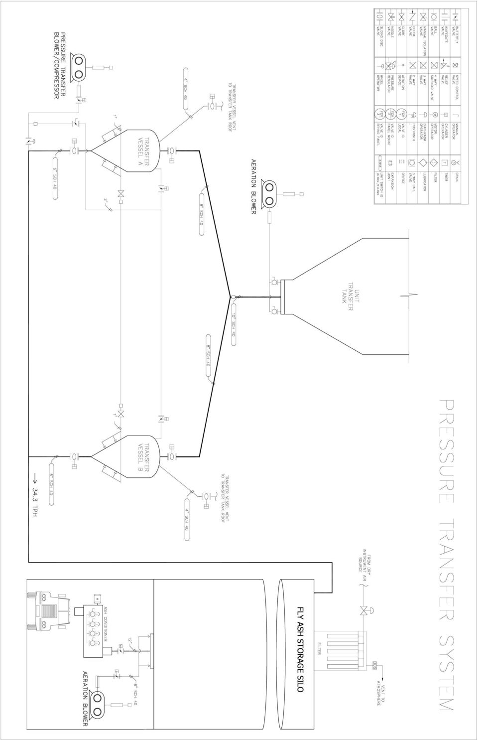
13 APPENDIX B Pressure System Flow Diagram

14
Pulverized Coal Pipe Testing and Balancing
 Pulverized Coal Pipe Testing and Balancing By Richard F. (Dick) Storm, PE The first step in optimizing combustion system performance is balancing the air and fuel flowing through each of the plant's coal
ACFM vs. SCFM vs. ICFM Series of Technical White Papers from Ohio Medical Corporation
 ACFM vs. SCFM vs. ICFM Series of Technical White Papers from Ohio Medical Corporation Ohio Medical Corporation 1111 Lakeside Drive Gurnee, IL 60031 Phone: (800) 448-0770 Fax: (847) 855-6304 info@ohiomedical.com
NFPA Combustible Dust Compliance and the Industrial Ventilation System
 NFPA Combustible Dust Compliance and the Industrial Ventilation System Presented By: Tom Kroeger PE tkroeger@kirkblum.com Kirk & Blum, a CECO Environmental Company Marty Schloss PE marty.schloss@schlossengineering.com
Air Eliminators and Combination Air Eliminators Strainers
 Description Air Eliminators and Combination Air Eliminator Strainers are designed to provide separation, elimination and prevention of air in piping systems for a variety of installations and conditions.
Fuller-Kinyon Pump: Dry Material Line Charger
 Fuller-Kinyon Pump: Dry Material Line Charger Ongoing innovations Outstanding results Pneumatic Conveying Expertise The original Fuller-Kinyon pump, invented in 1926, began a long line of innovative products
Centrifugal Fans and Pumps are sized to meet the maximum
 Fans and Pumps are sized to meet the maximum flow rate required by the system. System conditions frequently require reducing the flow rate. Throttling and bypass devices dampers and valves are installed
Equivalents & Conversion Factors 406 Capacity Formulas for Steam Loads 407 Formulas for Control Valve Sizing 408-409
 Engineering Data Table of Contents Page No. I II Formulas, Conversions & Guidelines Equivalents & Conversion Factors 406 Capacity Formulas for Steam Loads 407 Formulas for Control Sizing 408-409 Steam
MANURE COLLECTION AND TRANSFER SYSTEMS IN LIVESTOCK OPERATIONS WITH DIGESTERS. A. C. Lenkaitis GEA Farm Technologies Inc. (Houle USA), Naperville, IL
, Naperville, IL") MANURE COLLECTION AND TRANSFER SYSTEMS IN LIVESTOCK OPERATIONS WITH DIGESTERS A. C. Lenkaitis GEA Farm Technologies Inc. (Houle USA), Naperville, IL INTRODUCTION Manure collection systems are influenced
MANURE COLLECTION AND TRANSFER SYSTEMS IN LIVESTOCK OPERATIONS WITH DIGESTERS A. C. Lenkaitis GEA Farm Technologies Inc. (Houle USA), Naperville, IL INTRODUCTION Manure collection systems are influenced
Inert Gas Extinguishing System Two Minute Discharge Study. Gene Hill, P.E. Brad Stilwell
 Inert Gas Extinguishing System Two Minute Discharge Study Gene Hill, P.E. Brad Stilwell Page 2 ABSTRACT Fire testing per UL 2127 and FM 5600 was done with an inert gas extinguishing system utilizing IG-100,
Transforming Bottom Ash Into Fly Ash in Coal Fired Power Stations
 2009 World of Ash (WOCA) Conference - May 4-7, 2009 in Lexington, KY, USA http://www.flyash.info/ S. Kochert, Allen-Sherman-Hoff, et al Transforming Bottom Ash Into Fly Ash in Fired Power Stations MAR
Specific Volume of Liquid (Column 7). The volume per unit of mass in cubic feet per pound.
. The volume per unit of mass in cubic feet per pound.") Steam Tables What They Are How to Use Them The heat quantities and temperature/ pressure relationships referred to in this Handbook are taken from the Properties of Saturated Steam table. Definitions of
Steam Tables What They Are How to Use Them The heat quantities and temperature/ pressure relationships referred to in this Handbook are taken from the Properties of Saturated Steam table. Definitions of
I BAU HAMBURG Dry Product Handling
 IBAU HAMBURG Your efficient partner for modern and effective bulk material handling I BAU HAMBURG PLANT DESIGN - ENGINEERING - EPC-CONTRACTING CEMENT - THERMAL POWER - MINERALS Central Cone Silos Single
After close to 50 years working with an unloading
 NEUERO Continuous Ship Unloader for Feed Mill TOMAS KISSLINGER, NEUERO Industrietechnik, Germany A BSTRACT After close to 50 years working with an unloading system, a new system which would serve today
Pacific Pump and Power
 Pacific Pump and Power 91-503 Nukuawa Street Kapolei, Hawaii 96707 Phone: (808) 672-8198 or (800) 975-5112 Fax: (866) 424-0953 Email: sales@pacificpumpandpower.com Web: www.pacificpumpandpower.com Pumps
1 DESCRIPTION OF THE APPLIANCE
 1 DESCRIPTION OF THE APPLIANCE 1.1 INTRODUCTION The cast iron SF boilers are a valid solution for the present energetic problems, since they can run with solid fuels: wood and coal. These series of boilers
Plant Engineering Magazine - Saving energy through front end engineering
 http://www.manufacturing.net/ple/article/ca209063?text=thermal+oxidizer& Page 1 of 5 Welcome, Michael Herron. (Not Michael? Log in here.) Wednesday, May 26, 2004 Search for: thermal oxidizer in All of
COMPRESSED AIR ULTRASONIC LEAK DETECTION GUIDE
 COMPRESSED AIR ULTRASONIC LEAK DETECTION GUIDE COMPRESSOR ROOM INTAKE FILTER AIR COMPRESSOR AFTERCOOLER MOISTURE SEPARATOR RECEIVER MAIN FILTER SECONDARY FILTERS AND LUBRICATORS V 1406R Increased Productivity
CO 2 41.2 MPa (abs) 20 C
 20 C") comp_02 A CO 2 cartridge is used to propel a small rocket cart. Compressed CO 2, stored at a pressure of 41.2 MPa (abs) and a temperature of 20 C, is expanded through a smoothly contoured converging nozzle
comp_02 A CO 2 cartridge is used to propel a small rocket cart. Compressed CO 2, stored at a pressure of 41.2 MPa (abs) and a temperature of 20 C, is expanded through a smoothly contoured converging nozzle
SIZING AND CAPACITIES OF GAS PIPING (Not Adopted by the State of Oregon)
") (IFGS) SIZING AND CAPACITIES OF GAS PIPING (Not Adopted by the State of Oregon) (This appendix is informative and is not part of the code. This appendix is an excerpt from the 2006 International Fuel Gas
(IFGS) SIZING AND CAPACITIES OF GAS PIPING (Not Adopted by the State of Oregon) (This appendix is informative and is not part of the code. This appendix is an excerpt from the 2006 International Fuel Gas
RECTIFIER DESIGN FOR FUEL ETHANOL PLANTS
 RECTIFIER DESIGN FOR FUEL ETHANOL PLANTS By Daniel R. Summers, P.E. SULZER CHEMTECH USA, Inc. Presented at the AIChE Annual Meeting Advances in Distillation Equipment and Applications Paper 264b November
Appendix B: Water Treatment Scenarios from AMD Treat
 Appendix B: Water Treatment Scenarios from AMD Treat 103 of 104 Jeddo Tunnel Abandoned Mine Drainage Passive vs. Active Treatment Cost Estimates Provided by Office of Surface Mining AMD Treat Software
PULSATION REDUCTION BY ACOUSTIC FILTERS FOR METERING APPLICATIONS. Robert J. McKee Ray G. Durke
 PULSATION REDUCTION BY ACOUSTIC FILTERS FOR METERING APPLICATIONS Robert J. McKee Ray G. Durke Southwest Research Institute 6220 Culebra Road San Antonio, TX 78238 INTRODUCTION Because of the adverse effects
SIZING AND CAPACITIES OF GAS PIPING
 APPENDIX A (IFGS) SIZING AND CAPACITIES OF GAS PIPING (This appendix is informative and is not part of the code.) A.1 General. To determine the size of piping used in a gas piping system, the following
Design Criteria & Service Goals
 4.1 Design Life of Improvements The design life of a water system component is sometimes referred to as its useful life or service life. The selection of a design life is a matter of judgment based on
Performance of the Boiler and To Improving the Boiler Efficiency Using Cfd Modeling
 IOSR Journal of Mechanical and Civil Engineering (IOSR-JMCE) e-issn: 2278-1684,p-ISSN: 2320-334X, Volume 8, Issue 6 (Sep. - Oct. 2013), PP 25-29 Performance of the Boiler and To Improving the Boiler Efficiency
Element D Services Plumbing
 Medical Vacuum and Gas PART 1 - GENERAL 1.01 OVERVIEW A. This section addresses medical vacuum, waste anesthetic gas disposal, compressed air, oxygen, nitrous oxide, nitrogen and carbon dioxide systems.
Compressed Air Systems
 Efficiency Vermont Guide to Savings Helping Vermont businesses save energy and money Compressed Air Systems 888-921-5990 www.efficiencyvermont.com 1 Save money and optimize system performance Air compressors
On-Demand Ventilation Energy Saving in Industrial Applications
 On-Demand Ventilation Energy Saving in Industrial Applications Ales Litomisky, Ecogate, Inc. ABSTRACT The purpose of this paper is to describe innovative on-demand industrial ventilation. These on-demand
Linear Programming Supplement E
 Linear Programming Supplement E Linear Programming Linear programming: A technique that is useful for allocating scarce resources among competing demands. Objective function: An expression in linear programming
2.0 DESIGN CRITERIA FOR WATER DISTRIBUTION SYSTEMS
 2.0 DESIGN CRITERIA FOR WATER DISTRIBUTION SYSTEMS Water system improvements proposed for inclusion into Western s service area shall be designed in accordance with all appropriate AWWA standards, include
Introduction. Example of inverted cone silos
 Storage Silos 2 3 Introduction FLSmidth Ventomatic offers technologies in the fields of material handling, storage, packing and dispatching with particular experience and focus in the cement, fertilizers,
CENTRIFUGAL PUMP OVERVIEW Presented by Matt Prosoli Of Pumps Plus Inc.
 CENTRIFUGAL PUMP OVERVIEW Presented by Matt Prosoli Of Pumps Plus Inc. 1 Centrifugal Pump- Definition Centrifugal Pump can be defined as a mechanical device used to transfer liquid of various types. As
Stora Enso Fors Ltd Sweden
 THE ANALYSIS REPORT OF PLANT NO. 3 Cofiring of biomass - evaluation of fuel procurement and handling in selected existing plants and exchange of information (COFIRING) - Part 2 Stora Enso Fors Ltd Sweden
Research and Development Information
 Portland Cement Association Research and Development Information 5420 Old Orchard Road Skokie, IL U.S.A. 60077-1083 Fax (847) 966-9781 (847) 966-6200 PCA R&D Serial No. 2086 The Reduction of Resource Input
CHAPTER 2 HYDRAULICS OF SEWERS
 CHAPTER 2 HYDRAULICS OF SEWERS SANITARY SEWERS The hydraulic design procedure for sewers requires: 1. Determination of Sewer System Type 2. Determination of Design Flow 3. Selection of Pipe Size 4. Determination
(205) 670-5088 (205) 670-5863
 670-5088 (205) 670-5863") Ruth Ann Yongue Roxann Laird Senior Engineer Assistant Project Director rayongue@southernco.com rfleonar@southernco.com (205) 670-5088 (205) 670-5863 Southern Company Services Power Systems Development
Ruth Ann Yongue Roxann Laird Senior Engineer Assistant Project Director rayongue@southernco.com rfleonar@southernco.com (205) 670-5088 (205) 670-5863 Southern Company Services Power Systems Development
2 1/2 Pipe. 40 = height. the gauge pressure inside the vessel from the gauge pressure at the nozzle inlet as shown:
 116eering. Engineering. Engineering. Engineering. Engineerin Engineering Information SPECIFYING SPRAY NOZZLES Spray nozzles have three basic functions: meter flow distribute liquid break up a liquid stream
Dust Collector Approval and Certificate of Performance Applications, 30 CFR 33
 ASAP3010 Dust Collector Approval and Certificate of Performance Applications, 30 CFR 33 U.S. Department of Labor Mine Safety and Health Administration Approval and Certification Center Program Circular
HYDROSTATIC TEST PUMPS
 HYDROSTATIC TEST PUMPS MANUAL HYDROSTATIC TEST PUMPS Ideal for testing residential water lines. Also for pressure testing small pressure tanks, sprinkler, boiler and solar systems. Lightweight and easy
APPENDIX A RECOMMENDED RULES FOR SIZING THE WATER SUPPLY SYSTEM
 APPENDIX A RECOMMENDED RULES FOR SIZING THE WATER SUPPLY SYSTEM Because of the variable conditions encountered, it is impractical to lay down definite detailed rules of procedure for determining the sizes
INTRODUCTION SOME USES OF SPRAY NOZZLES INTRODUCTION TYPES OF SPRAY NOZZLES
 SOME USES OF SPRAY NOZZLES It is important that the nozzle you select is appropriate for your particular application Liquid sprays are used in a seemingly endless variety of applications Some of the more
Problems with Hypo: Best Design Practices for Smooth and Efficient Sodium Hypochlorite Feed Systems Chad Hantelman, City of Bremerton Jeff Zahller,
 Problems with Hypo: Best Design Practices for Smooth and Efficient Sodium Hypochlorite Feed Systems Chad Hantelman, City of Bremerton Jeff Zahller, PE, HDR Engineering Outline Common Options Available
Experimental Study on Super-heated Steam Drying of Lignite
 Advanced Materials Research Vols. 347-353 (2012) pp 3077-3082 Online available since 2011/Oct/07 at www.scientific.net (2012) Trans Tech Publications, Switzerland doi:10.4028/www.scientific.net/amr.347-353.3077
Ground Source Heat Pumps The Fundamentals. Southington, Connecticut 860 628 4622 John F. Sima III P.E.
 Ground Source Heat Pumps The Fundamentals Southington, Connecticut 860 628 4622 John F. Sima III P.E. Winter/Spring 2010 Ground Source Heat Pumps The Fundamentals TOPICS: Heat Pump Terminology Basic Physics
Guidelines for Preparing for a Temporary Steam Plant
 Guidelines for Preparing for a Temporary Steam Plant Trailer-Mounted Boilers Skid Mounted Boilers Mobile Boiler Rooms Mobile Feedwater Vans Mobile Steam Plants Emergency Preparedness Plan Table of Contents
Engineering Recommendation on: Accumulators Revised 6-17-99 Issued January 10, 1979 Page 1 of 7
 Issued January 10, 1979 Page 1 of 7 Accumulators have long been recognized by the industry as an effective means of maintaining good system balance by storing excess refrigerant as the condenser or evaporator
Pumps SELECTION OF A PUMP
 Pumps SELECTION OF A PUMP A water system needs to move the water produced from the source to its customers. In almost all cases in Minnesota, the source is at a lower elevation than the user so the water
Exhaust Calculation Booklet
 Exhaust Calculation Booklet American Dryer Corporation 88 Currant Road Fall River MA 02720-4781 Telephone: (508) 678-9000 / Fax: (508) 678-9447 e-mail: techsupport@amdry.com ADC Part No. 450450 Exhaust
One of the fundamental design elements that every
 Preliminary Design Information Before starting the water system design, you must assemble a collection of information. This includes information from the owner, the local utility, and the architect. Things
pdi PLASTIC DRUM INSTITUTE Plastic Drum Paneling Issues
 pdi PLASTIC DRUM INSTITUTE Plastic Drum Paneling Issues PANELING BACKGROUND This report will explain the causes of paneling and suggest some possible ways to eliminate or minimize the paneling of plastic
Emerging Technologies in Wastewater Collection Systems
 Keville Enterprises Emerging Technologies in Wastewater Collection Systems Douglas McCutchen, CCM Brian Karmasin, P.E., BCEE CMAA Annual Conference Oct 2008 San Francisco, California Today s s Presentation
CENTRIFUGAL PUMP SELECTION, SIZING, AND INTERPRETATION OF PERFORMANCE CURVES
 CENTRIFUGAL PUMP SELECTION, SIZING, AND INTERPRETATION OF PERFORMANCE CURVES 4.0 PUMP CLASSES Pumps may be classified in two general types, dynamic and positive displacement. Positive displacement pumps
Table 1 DENSITY Density Solids Percent By Volume
 Willard Says Useful stuff to know about hydraulic dredging. The Discharge Pipeline Slurry Density Slurry density is: Poorly understood. The ratio of the weights of a volume of slurry relative to an identical
POLYNOMIAL FUNCTIONS
 POLYNOMIAL FUNCTIONS Polynomial Division.. 314 The Rational Zero Test.....317 Descarte s Rule of Signs... 319 The Remainder Theorem.....31 Finding all Zeros of a Polynomial Function.......33 Writing a
HYDRAULIC ANALYSIS OF PIPE LINED WITH MADISON S 100% SOLIDS STRUCTURAL POLYURETHANE COATINGS
 HYDRAULIC ANALYSIS OF PIPE LINED WITH MADISON S 100% SOLIDS STRUCTURAL POLYURETHANE COATINGS Shiwei William Guan, Ph.D. Vice President, R&D and International Business Madison Chemical Industries Inc. 490
University of Iowa Power Plant
 University of Iowa Power Plant Contents Purpose... 2 History... 3 Cogeneration... 6 Boilers... 7 Environmental Impact... 10 Steam Turbine Generators... 12 Modernization... 14 Biomass Fuel Initiative...
ENERGY AUDIT REPORT MINIMUM REQUIREMENTS
 ENERGY AUDIT REPORT MINIMUM REQUIREMENTS Energy Audit Reports must contain the following: 1) Eligibility Criteria: a) Evidence demonstrating that the Eligibility Criteria were met. 2) Participant Information:
The Fate of Ammonia and Mercury in the Carbon Burn-Out (CBO ) Process
 Process") The Fate of Ammonia and Mercury in the Carbon Burn-Out (CBO ) Process Vincent M Giampa Progress Materials, Inc., One Progress Plaza, St. Petersburg, Florida 33701 KEYWORDS: mercury, ammonia, carbon burn-out,
The Fate of Ammonia and Mercury in the Carbon Burn-Out (CBO ) Process Vincent M Giampa Progress Materials, Inc., One Progress Plaza, St. Petersburg, Florida 33701 KEYWORDS: mercury, ammonia, carbon burn-out,
DRYER VENTING SPECIFICATIONS DRYER SAFETY
 DRYER VENTING SPECIFICATIONS Table of Contents DRYER SAFETY...1 INSTALLATION REQUIREMENTS...4 Venting Requirements...5 DRYER INSPECTION AND CLEANING...7 Frequency of Exhaust System Cleaning...7 Inspecting
APPENDIX M-2 SANITARY SEWER TECHNICAL MEMORANDUM. Stadium Reconstruction EIR
 APPENDIX M-2 SANITARY SEWER TECHNICAL MEMORANDUM Stadium Reconstruction EIR Appendices \ AECOM Technical Services, Inc 401 West A Street Suite 1200 San Diego, CA 92101 www.aecom.com 619-610-7600 tel 619-610-7601
With the background of fulfilling public commitments for ECONO-PILOT ENERGY-SAVING SYSTEM FOR WATER PUMPS
 ECONO-PILOT ENERGY-SAVING SYSTEM FOR WATER PUMPS SAWAI Tsuneji *1 TAKAHASHI Hiroshi *1 INOUE Ken-ichi *2 We have developed the Econo-Pilot energy-saving system for water pumps, which reduces the power
WHAT YOU DON T KNOW ABOUT ACCUMULATORS CAN KILL YOU!
 WHAT YOU DON T KNOW ABOUT ACCUMULATORS CAN KILL YOU! Atlanta (Monroe) GA 770-267-3787 gpm@gpmhydraulic.com www.gpmhydraulic.com What You Don t Know About Hydraulic Accumulators Can Kill You TABLE OF CONTENTS
Manufacturing Quality Concrete Products
 CEMEX USA - Technical Bulletin 8.0 Manufacturing Quality Concrete Products Establishing or Upgrading a Quality Program Overview The following guidelines were developed for MCP (manufactured concrete products)
EMERGENCY VAPOR SCRUBBER SYSTEMS
 EMERGENCY VAPOR SCRUBBER SYSTEMS Toxic gases such as chlorine, sulfur dioxide and ammonia are commonly used for water and wastewater treatment, and in many industrial fabrication processes. The Uniform
Troubleshooting Your RO
 Troubleshooting Your RO Summary: There can be many reasons why a RO system suffers a loss in performance, and is unable to produce the proper quantity and/or quality of permeate water. Similar to a doctor
Green Thread Product Data
 Green Thread Product Data Applications Dilute Acids Caustics Produced Water Industrial Waste Hot Water Condensate Return Materials and Construction All pipe manufactured by filament winding process using
Approval Standard for Plastic Suspended Ceiling Panels
 Approval Standard for Plastic Suspended Ceiling Panels Class Number 4651 February 1978 2002 FM Approvals LLC. All rights reserved. Foreword The FM Approvals certification mark is intended to verify that
Self-Discharging Cement Carrier
 I BAU HAMBURG A MEMBER OF THE HAVER GROUP Information Self-Discharging Cement Carrier Cement Carriers Advanced I BAU technology for self-discharging Cement Carriers The trade of cement and similar products
Pedestrian Struck By Forklift
 Pedestrian Struck By Forklift Lessons Learned Volume 01 Issue 01 2004 USW Pedestrian Struck By Forklift Purpose To conduct a small group lessons learned activity to share information gained from incident
HS-901(A) BASIC STEAM HEATING SYSTEMS
 BASIC STEAM HEATING SYSTEMS") HS-901(A) BASIC HEATING SYSTEMS One-Pipe Two-Pipe Basic Steam Heating Systems One-pipe steam heating system EQUALIZER SAFETY FACTOR STATIC HEAD PRESSURE DROP 2" HEATING UNIT 15" DRIP CONNECTION In a one-pipe,
HS-901(A) BASIC HEATING SYSTEMS One-Pipe Two-Pipe Basic Steam Heating Systems One-pipe steam heating system EQUALIZER SAFETY FACTOR STATIC HEAD PRESSURE DROP 2" HEATING UNIT 15" DRIP CONNECTION In a one-pipe,
Select the Right Relief Valve - Part 1 Saeid Rahimi
 Select the Right Relief Valve - Part 1 Saeid Rahimi 8-Apr-01 Introduction Selecting a proper type of relief valve is an essential part of an overpressure protection system design. The selection process
Commercial refrigeration has been in the environmental. Refrigerant. as a. Basics Considerations PART 1:
 PART 1: CO 2 Commercial refrigeration has been in the environmental spotlight for more than a decade, especially as leakage studies have revealed the true effects of hydrofluorocarbon (HFC) emissions.
HOW TO SELECT A LOW VOLUME (L.V ) BOILER
 BOILER") HOW TO SELECT A LOW VOLUME (L.V ) BOILER FREQUENTLY ASKED QUESTIONS OR COMMENTS ON BOILERS Dear Potential Customer: Low Volume Operator Exempt boilers have been marketed in Ontario to eliminate the requirement
HOW TO SELECT A LOW VOLUME (L.V ) BOILER FREQUENTLY ASKED QUESTIONS OR COMMENTS ON BOILERS Dear Potential Customer: Low Volume Operator Exempt boilers have been marketed in Ontario to eliminate the requirement
XV80 UPFLOW/HORIZONTAL 2-STAGE, VARIABLE SPEED GAS-FIRED FURNACE
 UPF/HORIZONTAL 2-, VARIABLE SPEED GAS-FIRED FURNACE XV80 MODELS TUD2B060A9V3VB, TUD2B080A9V3VB TUD2C080A9V4VB, TUD2C080B9V4VB TUD2B00A9V3VB, TUD2C00A9V5VB TUD2C00B9V5VB, TUD2DA9V5VB TUD2DB9V5VB, TUD2DA9V5VB
VAV Laboratory Room Airflow The Lowdown on Turndown
 Technology Report March, 2003 VAV Laboratory The Lowdown on Turndown Turndown comparison of these two turndown ratios. Note the small actual airflow difference between them. control ranges are normally
TECHNIQUES FOR NATURAL GAS SAMPLING A DISCUSSION OF FIELD METHODS FOR OBTAINING SPOT SAMPLES. Randall Messman SW Regional Sales Manager
 TECHNIQUES FOR NATURAL GAS SAMPLING A DISCUSSION OF FIELD METHODS FOR OBTAINING SPOT SAMPLES Randall Messman SW Regional Sales Manager PGI International 16101 Vallen Drive Houston, TX 77041 Purpose Natural
Technical Information
 Determining Energy Requirements - & Gas Heating & Gas Heating and gas heating applications can be divided into two conditions, air or gas at normal atmospheric pressure and air or gas under low to high
Example Calculations Evaluation for Fine Bubble Aeration System. Red Valve Company, Inc. 700 NORTH BELL AVENUE CARNEGIE, PA 15106-0548
 Revision Date 6/10/02 9:52 Red Valve Company, Inc. 700 NORTH BELL AVENUE CARNEGIE, PA 15106-0548 PHONE (412) 279-0044 FAX (412) 279-5410 Red Valve Representative Sample Air Diffuser Calcs.xls Input Data
M7RL Series TECHNICAL SPECIFICATIONS. FEATURES and BENEFITS. High Efficiency / Direct Vent Condensing Downflow Gas Furnace
 TECHNICAL SPECIFICATIONS M7RL Series High Efficiency / Direct Vent Condensing Downflow Gas Furnace Induced Draft - 9%+ AFUE Input 4,000 thru 7,000 Btuh The high efficiency downflow gas furnace is especially
Waste, Just Another Resource: A Case for Waste Water
 Energy Engineering ISSN: 0199-8595 (Print) 1546-0118 (Online) Journal homepage: http://www.tandfonline.com/loi/uene20 Waste, Just Another Resource: A Case for Waste Water David Goodman, Arash Edalatnoor
UNIT 1 MASS AND LENGTH
 UNIT 1 MASS AND LENGTH Typical Units Typical units for measuring length and mass are listed below. Length Typical units for length in the Imperial system and SI are: Imperial SI inches ( ) centimetres
Pressure Vessels (Air Compressors) and LPG Tanks
 and LPG Tanks") Pressure Vessels (Air Compressors) and LPG Tanks 1. Identification of Workplace Hazard Any container, tank or vessel that contains pressurized material is a potential hazard to employees due to the force
Pressure Vessels (Air Compressors) and LPG Tanks 1. Identification of Workplace Hazard Any container, tank or vessel that contains pressurized material is a potential hazard to employees due to the force
How To Handle A Pneumatic Conveying System
 The New Thinking in The New Thinking in 1 3 Introduction Technology Content 4 What Causes Attrition? 5 Recommendations to Reduce the Formation of Dust and Streamers 6 Pelletron s Solution for Gentle Material
Turbo Tech 101 ( Basic )
") Turbo Tech 101 ( Basic ) How a Turbo System Works Engine power is proportional to the amount of air and fuel that can get into the cylinders. All things being equal, larger engines flow more air and as
Turbo Tech 101 ( Basic ) How a Turbo System Works Engine power is proportional to the amount of air and fuel that can get into the cylinders. All things being equal, larger engines flow more air and as
Pipe Sizes For Water Distribution System Design
 Appendix D Pipe Sizes For Water Distribution System Design D-. This appendix contains information to help determine pipe sizes when designing a water distribution system. Use Table D- and Tables D- through
Layout Planning of Waste-to-Energy Plants
 Layout Planning of Waste-to-Energy Plants Layout Planning of Waste-to-Energy Plants Falko Weber The layout planning of waste incineration and solid recovered fuel power plants is subject to certain local
GRADATION OF AGGREGATE FOR CONCRETE BLOCK
 GRADATION OF AGGREGATE FOR CONCRETE BLOCK Although numerous papers have been written concerning the proper gradation for concrete mixes, they have generally dealt with plastic mixes, and very little published
The Piping System Model a New Life Cycle Document. Elements of the Piping System Model
 Piping System Model as a Life Cycle Document White Paper Introduction When designing piping systems, a variety of documents are created providing the details necessary to design, purchase, build, and test
Energy Audits Waste Water Treatment Plants
 Energy Audits Waste Water Treatment Plants Ohio Water Environment Association Conference June 20, 2012 Presented by: Samuel J. Morgan, P.E., LEED AP CT Consultants, Inc. World Energy Trend US Total Energy
Physics 221 Experiment 5: Magnetic Fields
 Physics 221 Experiment 5: Magnetic Fields August 25, 2007 ntroduction This experiment will examine the properties of magnetic fields. Magnetic fields can be created in a variety of ways, and are also found
MOSS WOOD BOILER SYSTEMS
 GEORGE K. MOSS CO., INC. INSIDE THIS ISSUE: WOOD WATER T U- TUBE BOILER WOOD FIREBOX BOILER WOOD HYBRID BOILER GASIFIER COM B- BUSTION SYS- TEM PNEUMATIC COMBUSTION SYSTEM WOOD BOILER PLC CONTROLS PLC
Gas Line Sizing. Z Maximum gas demand shall be determined by adding all of the equipment Btu ratings from appliances connected on the system.
 Gas Line Sizing When sizing Gas piping systems certain factors must be considered. They are: Z It shall provide sufficient gas to meet the maximum demand of the gas equipment. Piping must be sized to supply
RECON WATER HEATER INSTALLATION FORM
 RECON WATER HEATER INSTALLATION FORM Please complete ONE (1) form for each SITE and return to AERCO for warranty validation within 30 days of start-up. After completion, e-mail this form to: STARTUP@AERCO.COM.
Advanced Heating & Hot Water Systems. Ultra High Efficiency Energy Star Listed Condensing Boiler
 Advanced Heating & Hot Water Systems A Trailblazing Energy Star Listed Boiler that Installs like a Mid-Efficiency Boiler with the Performance of a High-Efficiency Product Ultra High Efficiency Energy Star
The Jockey Pump, an Important Part of a Fire Pump System.
 The Jockey Pump, an Important Part of a Fire Pump System. May 18, 2008 A Jockey Pump is an important component of a fire pump system. The Jockey Pump is not as mundane, as many engineers, contractors and
OSHA Tank Venting DEFINITIONS
 OSHA Tank Venting DEFINITIONS 1910.106 - Flammable and combustible liquids. 1910.106(a)(2) (a) Definitions. As used in this section: (2) Atmospheric tank shall mean a storage tank which has been designed
Effective Means of Handling Sand-Laden Dairy Manure. by:
 Effective Means of Handling Sand-Laden Dairy Manure by: Curt Gooch 1, P.E. and Andrew Wedel 2, P.E. Introduction Are you a producer who would like to bed your cows with sand but have experienced or heard
PLANT LOCATION AND LAYOUT
 PLANT LOCATION AND LAYOUT The Location Of The Plant Can Have A Crucial Effect On The Profitability Of A Project, And The Scope For Future Expansion. Many Factors Must Be Considered When Selecting A Suitable