user's manual _19
|
|
|
- Heather Blankenship
- 9 years ago
- Views:
Transcription
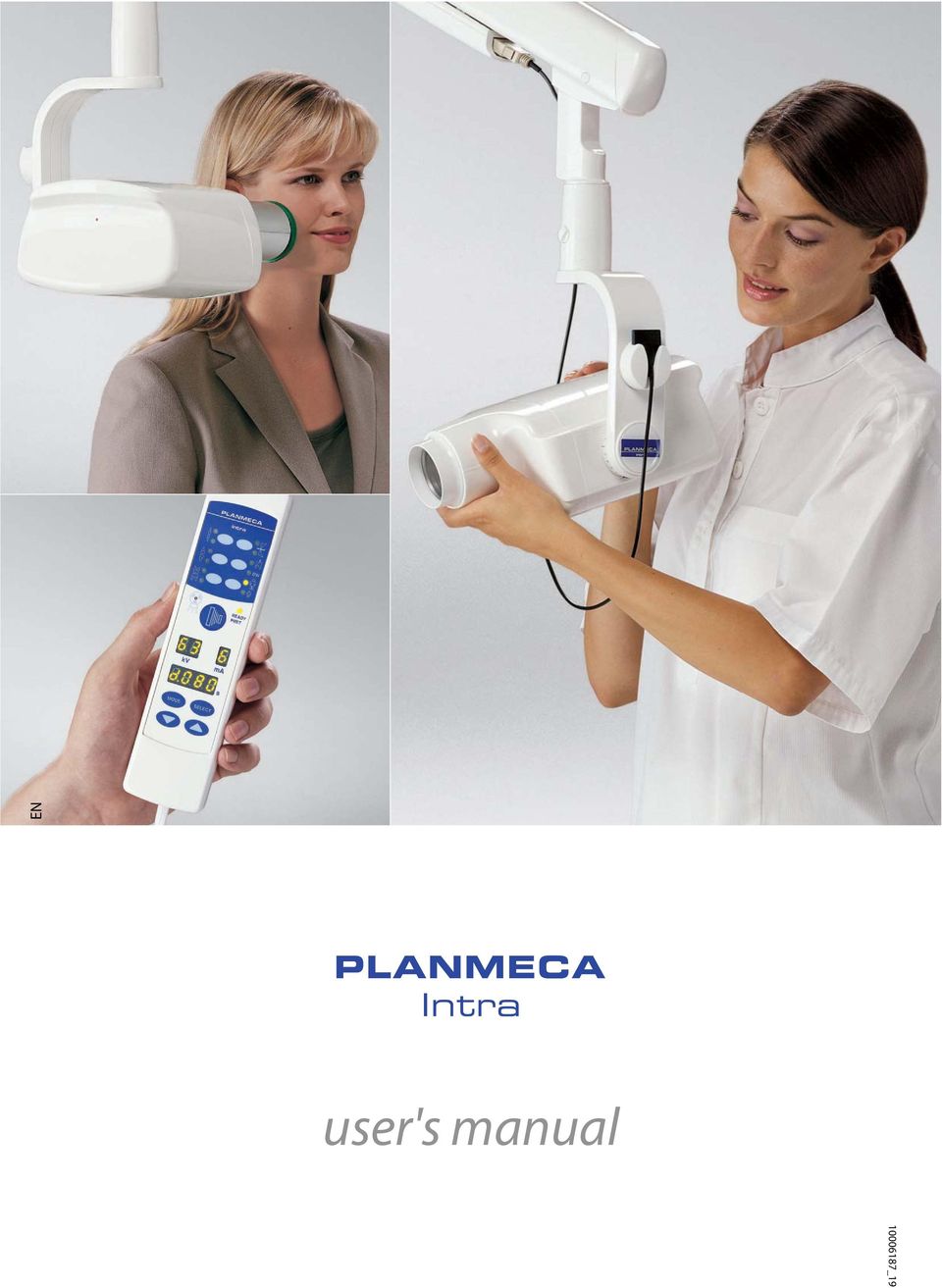
1 EN user's manual _19
2

3 TABLE OF CONTENTS 1 INTRODUCTION Symbols WARNINGS AND PRECAUTIONS CHECKLIST - BEFORE USING THE UNIT PLANMECA INTRA X-RAY UNIT - MAIN PARTS General view of the X-ray Control panel PREPARATIONS FOR THE EXPOSURE Switching the unit on Selecting the cone... 6 CONTROL PANEL Displays Keys and indicator lights MOLAR EXPOSURE Selecting the exposure parameters Patient positioning Taking an exposure... 1 PREMOLAR AND CANINE EXPOSURE Selecting the exposure parameters Patient positioning Taking an exposure INCISOR EXPOSURE Selecting the exposure parameters Patient positioning Taking an exposure OCCLUSAL EXPOSURE Selecting the exposure parameters Patient positioning Taking an exposure ENDODONTIC EXPOSURE BITE-WING EXPOSURE Selecting the exposure parameters Patient positioning Taking an exposure EXPOSURE VALUES Default exposure values Preprogrammed settings values PROGRAMMING THE EXPOSURE VALUES Programming the default exposure and density values Programming the preprogrammed settings CLEANING Surfaces User s Manual Planmeca Intra X-ray Unit i

4 TABLE OF CONTENTS 15.2 Film holder SERVICE EXPOSURE VALUE TABLES Exposure values for speed F films Exposure values for Dixi2 V1 sensors (high sensitivity) Exposure values for Dixi2 V3 sensors ERROR CODES DISPOSAL OF THE UNIT TECHNICAL SPECIFICATIONS Technical data Dimensions (in mm) User s statement for Planmeca Intra The manufacturer, assembler, and importer are responsible for the safety, reliability and performance of the unit only if: - installation, calibration, modification and repairs are carried out by qualified authorized personnel - electrical installations are carried out according to the appropriate requirements such as IEC364 - equipment is used according to the operating instructions Planmeca pursues a policy of continual product development. Although every effort is made to produce up-to-date product documentation this publication should not be regarded as an infallible guide to current specifications. We reserve the right to make changes without prior notice. COPYRIGHT PLANMECA Publication part number Version 19 ii Planmeca Intra X-ray Unit User s Manual

5 INTRODUCTION 1 INTRODUCTION This manual describes how to operate the Planmeca Intra X-ray unit and the Planmeca Intra equipped with Dixi digital X-ray system. Please read these instructions thoroughly before using the unit. Note that if you use the Dixi digital Intra X-ray system, you need a PC with a Planmeca Dimaxis imaging software to save, view and modify the radiographs. The Dimaxis software has a separate manual, which should be used in conjunction with this manual. Federal law restricts this device to sale by or on the order of a dentist. This manual is valid for software revisions 3.0 or later. The Planmeca Intra X-ray unit is allowed to be used only under supervision of a dental/health care professional The Planmeca Intra X-ray unit fulfills the requirements of Directive 93/42/EEC. All key illustrations indicate that the key should be pressed or, where indicated, pressed and held down. Pressing a key will either switch a function on or off, depending on the original setting, or change the indicated value. The display values shown in this guide are only examples and should not be interpreted as recommended values unless otherwise stated. Make sure that you are fully acquainted with the appropriate radiation protection measures and these instructions before using the unit. User s Manual Planmeca Intra X-ray Unit 1

6 INTRODUCTION 1.1 Symbols Type B equipment (Standard IEC 601-1). Alternating current (Standard IEC-417). Attention, consult accompanying documents (Standard IEC 601-1). Intermediate focal spot (Standard IEC-417). Separate collection for electrical and electronic equipment according to Directive 2002/96/EC (WEEE). 2 Planmeca Intra X-ray Unit User s Manual
.")
7 WARNINGS AND PRECAUTIONS 2 WARNINGS AND PRECAUTIONS IT IS VERY IMPORTANT THAT THE PLACE WHERE THE UNIT IS TO BE USED AND THE POSITION FROM WHICH THE USER IS TO OPERATE THE UNIT ARE CORRECTLY SHIELDED. SINCE RADIATION SAFETY REQUIREMENTS VARY FROM COUNTRY TO COUNTRY AND STATE TO STATE IT IS THE RESPONSIBILITY OF THE USER TO ENSURE THAT ALL LOCAL SAFETY REQUIREMENTS ARE MET. CAUTION This X-ray unit may be dangerous to both patient and operator unless safe exposure values are used and correct operating procedures are observed. Electromagnetic interference between the equipment and other devices can occur in very extreme conditions. Do not use the equipment in close conjunction with sensitive devices, or devices creating high electromagnetic disturbances. CAUTION The SIP/SOP shall not be used in Intra, but only for connection of Dixi equipment. User s Manual Planmeca Intra X-ray Unit 3

8 CHECKLIST - BEFORE USING THE UNIT 3 CHECKLIST - BEFORE USING THE UNIT Make sure that you are fully acquainted with the appropriate radiation protection measures and these instructions before using the unit. Make sure that the film processor is in working order and is ready for use. Make sure that you are using the correct film processing chemicals for the film you are using. Make sure that the processing chemicals you are using are fresh and are at the correct processing temperatures and concentrations. Make sure that the film you are going to use is fresh. Do not use old film. Store and handle the film according to the manufacturer s instructions. 4 Planmeca Intra X-ray Unit User s Manual

9 kv MODE READY PRET SELECT BW s PLANMECA INTRA X-RAY UNIT - MAIN PARTS 4 PLANMECA INTRA X-RAY UNIT - MAIN PARTS 4.1 General view of the X-ray Support arm Scale for cone angle Generator box Control panel Tube head Horizontal tube head stiffness adjustment screw Adjust the stiffness of the tube head horizontal movement by turning the adjustment screw on the support axle manually or with a wrench tool (see next page). The stiffness of the tube head horizontal movement has been preadjusted at the factory, and can be changed by the user, if necessary. Turn the adjustment screw 0,5-1 rounds clockwise if you want to tighten the tube head and 0,5-1 rounds counterclockwise to loosen it. Do not turn the adjustment screw too much counterclockwise to avoid the screw to come loose. User s Manual Planmeca Intra X-ray Unit 5

10 MODE kv SELECT s READY PRET PLANMECA INTRA X-RAY UNIT - MAIN PARTS intra_stiffness.eps Horizontal tube head stiffness adjustment screw 4.2 Control panel BW One end of the control panel cable is connected to the terminal at the underside of the generator box, and the other end to the control panel. CAUTION Do not connect any other equipment to the control panel s terminal. 6 Planmeca Intra X-ray Unit User s Manual

11 Complies with DHHS radiation performance standards 21 CFR Subchapter J. 220V V AT 70kV maximum 100 s/h 100V V 15 AT Total filtration: 2,0 mm EquAl WARNING: 1000VA 50/60Hz For continued protection Manufactured by: against risk of fire replace Planmeca OY only with same type and 000 HELSINKI rating of fuse. FINLAND LBL-Z-006D 0537 kv MODE READY PRET SELECT BW s 5 PREPARATIONS FOR THE EXPOSURE 5.1 Switching the unit on PREPARATIONS FOR THE EXPOSURE The on/off switch is located under the generator box. When the unit is switched on it will carry out an automatic self-test during which the Display CPU software version is shown on the kv display, and the Tube head CPU software version on the time display. I_6.eps On/off switch After the self-test is completed the default exposure values will appear on the displays. The default exposure values can be reprogrammed by the user, see section 14.1 Programming the default exposure and density values on page 39. There are two sets of default exposure values: one for the mode and one for the mode. The unit is always in the mode when it is switched on. User s Manual Planmeca Intra X-ray Unit 7

12 PREPARATIONS FOR THE EXPOSURE 5.2 Selecting the cone Select the cone to be used in the exposure. It is recommended to use the optional long cone in order to keep the absorbed dose to the patient as low as possible. Long 30 cm (12 ) cone The long cone is attached into its position by pushing it into the short cone and rotating it so that the red point on the short cone and the black point on the long cone are in line. Attach/remove: red points in line. In position: red and black points in line. HAWE film holder Rectangular collimator The rectangular collimator can be attached to the long cone either before the film holder or after it. When the collimator is attached before the film holder, the film holder rotates when the collimator is rotated. Film holder Film holder Rectangular collimator Planmeca Intra X-ray Unit User s Manual

13 PREPARATIONS FOR THE EXPOSURE When attaching the film to the holder make sure that the film is in the same direction as the rectangular collimator. Film and collimator sides in the same direction The exposure values must be selected according to the cone used in the exposure, refer to the section 13 EXPOSURE VALUES on page 36. RINN film holder Attach the RINN compatible rectangular collimator to the long cone. The film holder can be attached to the collimator. RINN compatible rectangular collimator RINN film holder User s Manual Planmeca Intra X-ray Unit 9

14 PREPARATIONS FOR THE EXPOSURE Long rectangular cone Push the rectangular cone into the short cone so that the red dots on the short cone and on the rectangular cone are in line (1), and rotate the cone 10, until the black dot on the rectangular cone and the red dot on the short cone are in line (2). The cone can be now rotated in its position ±90. trotonen eps Red points The rectangular cone can be removed when the red dots on the short cone and on the rectangular cone are in line. 10 Planmeca Intra X-ray Unit User s Manual

15 CONTROL PANEL 6 CONTROL PANEL Preprogrammed setting keys and indicator lights Exposure warning indicator light Preprogrammed setting keys and indicator lights Adult/ selection key and indicator lights Ready indicator light Exposure key kv display display Time display MODE key SELECT key Parameter adjustment keys 6.1 Displays kv display The selected kv value is shown on the kv display. There are eight different values that can be selected: 50, 52, 55, 57, 60, 63, 66 and 70 kv. The kv range can be 50-70, 55-70, 60-70, 66-70, 70, 50-6, 55-6, 60-6, 66-6 or 6 depending on the local requirements. display The selected value is shown on the display. There are seven different values that can be selected: 2 -. The minimum available value depends on the local requirements. User s Manual Planmeca Intra X-ray Unit 11

16 CONTROL PANEL Time display Film-based imaging mode The selected exposure time is shown on the time display. After taking an exposure a waiting time starts to flash on the time display which indicates the delay before the next exposure can be taken. In the digital imaging mode the exposure time is shown with the prefix d. Digital imaging mode In the phosphoric mode the exposure time is shown with the prefix P.. Phosphoric mode 6.2 Keys and indicator lights Preprogrammed setting keys and indicator lights Incisors Premolars and canines Molars Occlusal exposure The selections that can be made are: molars, premolars & canines, incisors, occlusal exposure, endodontic and bitewing. Endodontic Bite-wing Adult/ mode selection The unit is preprogrammed with exposure parameters - time, kv and values - which can be selected by pressing these keys. There are ten sets of parameters for both the mode and the mode: one for each exposure region and one for default exposure values, which are in use when an exposure region is not selected. Press the desired key once to select the projection of the maxilla. The indicator light of the selected projection will come on. Press the key twice to select the projection of the mandible. The indicator light of the selected projection will come on. Pressing the key a third time will recall the default exposure values. The preprogrammed settings can be changed by the user, see section 14 PROGRAMMING THE EXPOSURE VALUES on page Planmeca Intra X-ray Unit User s Manual

17 CONTROL PANEL Adult/ mode selection key and indicator light Press the / mode selection key once to select the mode. The indicator light of the mode will come on. Press the key again to return to the mode. The indicator light of the mode will come on. SELECT key Press the SELECT key briefly to select the parameter - kv, or exposure time - to be changed. When the parameter value is flashing on the display, the parameter can be changed. After adjusting the kv or value or exposure time the unit will return automatically to the time adjustment mode after 5 seconds time. Press and hold down the SELECT key (about 4 seconds) until you have heard two signal tones to enter the programming mode. For more information about programming refer to chapter 14.1 Programming the default exposure and density values on page 39. Press the SELECT key to clear the error from the display. MODE key Film-based imaging mode Digital imaging mode Phosphoric mode Press the MODE key and hold it down for 2 seconds to select the exposure parameters for film, digital or phosphor plate imaging. Press the MODE key and hold it down for 2 seconds to enter the digital imaging mode from the film-based imaging mode. There is no prefix on the display in the film-based imaging mode. The exposure time with prefix d. appears on the time display in the digital imaging mode. All the keys function as in the film-based imaging mode. Press the MODE key and hold it down for 2 seconds to enter the phosphoric mode from the digital imaging mode. The exposure time with prefix P. appears on the time display in the phosphoric mode. All the keys function as in the film-based imaging mode. All the exposure parameters remain selected after the exposure until the user changes the parameters or until the unit is switched off. User s Manual Planmeca Intra X-ray Unit 13

18 CONTROL PANEL Parameter adjustment keys down up Press the SELECT key briefly to select the parameter - kv,, exposure time or density - to be changed. When the parameter value is flashing on the display, the parameter can be changed with the parameter adjustment keys. The up key increases the value and the down key decreases it. After adjusting the kv or value or exposure time the unit will return automatically to the time adjustment mode after 5 seconds time. Ready indicator light The green ready indicator light will come on when the unit is ready to take an exposure. The waiting time between exposures is 15 times exposure time, but always at least 6 seconds. In the programming mode the ready light will start to flash. Planmeca Intra with Dixi3 system: You can set the unit so that the Ready indicator light will only come on when the Dimaxis program is ready for the exposure, i.e. Waiting for exposure message appears on the computer screen. To change the settings of the unit contact your Planmeca technical support. Exposure key When you take an exposure you must press and hold down the exposure key for the duration of the exposure. Exposure warning indicator light The yellow exposure warning light will come on when you take an exposure. You will also hear an audible warning sound during the exposure. 14 Planmeca Intra X-ray Unit User s Manual

19 MOLAR EXPOSURE 7 MOLAR EXPOSURE 7.1 Selecting the exposure parameters The preprogrammed exposure values are shown in section 13 EXPOSURE VALUES on page 36. Film-based imaging mode Phosphoric mode Check that you are in the desired mode: in the film-based imaging mode, in the digital imaging mode or in the phosphoric mode. Digital imaging mode The imaging mode can be changed by pressing the MODE key for 2 seconds. Select the or mode. The indicator light of the selected projection will come on. Child Adult Molars Select the molar exposure region with the preprogrammed setting keys. Press the molar key once to select the projection of the maxilla, and press the key twice to select the projection of the mandible. The indicator light of the selected projection will come on. The preprogrammed time, kv and values appear on the respective displays. The preprogrammed time, kv and values can be temporarily changed with the parameter adjustment keys. This will not affect the preprogrammed values. User s Manual Planmeca Intra X-ray Unit 15

20 MOLAR EXPOSURE Select the parameter to be adjusted with the SELECT key. When the parameter value is flashing on the kv display, the anode voltage can be changed with the parameter adjusting keys. When the parameter value is flashing on the display, the anode current can be changed with the parameter adjusting keys. When the parameter value on the kv or display is not flashing, the exposure time value can be changed with the parameter adjusting keys. After adjusting the kv or value the unit will return automatically to the time adjustment mode after 5 seconds time. 7.2 Patient positioning Ask the patient to sit down. Place a protective lead apron over the patient s chest. Positioning the film/sensor Paralleling technique (recommended) The film or sensor is placed to a film holder which is used to align the film parallel to the long axis of the tooth. Use a long cone for the paralleling technique. Long axis of the tooth Film or sensor 16 Planmeca Intra X-ray Unit User s Manual

21 MOLAR EXPOSURE Bisecting angle technique (optional) The patient holds the film or sensor in place with his finger. The X-ray beam is directed perpendicularly towards an imaginary line which bisects the angle between the film plane and the long axis of the tooth. Long axis of the tooth Film or sensor Positioning the cone Scale for the cone angle The angle of the cone is indicated on the scale located on the vertical joint of the tube head. The optional long cone can be attached into the short cone. Refer to chapter 5.2 Selecting the cone on page. Select the cone angle from the table below. TEETH ANGLE OF INCLINATION Molars Maxilla +35 Molars Mandible -5 Position the cone according to the figures below. Maxillary molar Mandibular molar User s Manual Planmeca Intra X-ray Unit 17
22 MODE SELECT BW READY PRET MOLAR EXPOSURE 7.3 Taking an exposure Ask the patient to remain as still as possible. Move as far away from the X-ray tube as the length of the cable from the control panel permits. The distance must be at least 2 meters (6.6 ft) from the X-ray tube. No one except the patient may remain in the radiation area while the exposure is taken. Maintain audio and visual contact with the patient and unit during the exposure. Check that the ready light is on. Press and hold the exposure key on the control panel for the duration of the exposure. kv s The exposure warning light will come on. You will also hear the radiation warning tone during the exposure. 1 Planmeca Intra X-ray Unit User s Manual
23 PREMOLAR AND CANINE EXPOSURE PREMOLAR AND CANINE EXPOSURE.1 Selecting the exposure parameters The preprogrammed exposure values are shown in section 13 EXPOSURE VALUES on page 36. Film-based imaging mode Phosphoric mode Check that you are in the desired mode: in the film-based imaging mode, in the digital imaging mode or in the phosphoric mode. Digital imaging mode The imaging mode can be changed by pressing the MODE key for 2 seconds. Select the or mode. The indicator light of the selected projection will come on. Child Adult Premolars and canines Select the premolar and canine exposure region with the preprogrammed setting keys. Press the premolar and canine key once to select the projection of the maxilla, and press the key twice to select the projection of the mandible. The indicator light of the selected projection will come on. A m The preprogrammed time, kv and values appear on the respective displays. The preprogrammed time, kv and values can be temporarily changed with the parameter adjustment keys. This will not affect the preprogrammed values. User s Manual Planmeca Intra X-ray Unit 19
24 PREMOLAR AND CANINE EXPOSURE Select the parameter to be adjusted with the SELECT key. When the parameter value is flashing on the kv display, the anode voltage can be changed with the parameter adjusting keys. When the parameter value is flashing on the display, the anode current can be changed with the parameter adjusting keys. When the parameter value on the kv or display is not flashing, the exposure time value can be changed with the parameter adjusting keys. After adjusting the kv or value the unit will return automatically to the time adjustment mode after 5 seconds time..2 Patient positioning Ask the patient to sit down. Place a protective lead apron over the patient s chest. Positioning the film/sensor Paralleling technique (recommended) The film or sensor is placed to a film holder which is used to align the film parallel to the long axis of the tooth. Use a long cone for the paralleling technique. Long axis of the tooth Film or sensor 20 Planmeca Intra X-ray Unit User s Manual
25 PREMOLAR AND CANINE EXPOSURE Bisecting angle technique (optional) The patient holds the film or sensor in place with his finger. The X-ray beam is directed perpendicularly towards an imaginary line which bisects the angle between the film plane and the long axis of the tooth. Long axis of the tooth Film or sensor Positioning the cone Scale for the cone angle The angle of the cone is indicated on the scale located on the vertical joint of the tube head. The optional long cone can be attached into the short cone. Refer to chapter 5.2 Selecting the cone on page. Select the cone angle from the table below. Premolars and canine teeth Premolars and canine teeth TEETH Maxilla +45 Mandible -10 ANGLE OF INCLINATION Position the cone according to the figure below. Maxillary premolar and canine Mandibular premolar and canine User s Manual Planmeca Intra X-ray Unit 21
26 MODE SELECT BW READY PRET PREMOLAR AND CANINE EXPOSURE.3 Taking an exposure Ask the patient to remain as still as possible. Move as far away from the X-ray tube as the length of the cable from the control panel permits. The distance must be at least 2 meters (6.6 ft) from the X-ray tube. No one except the patient may remain in the radiation area while the exposure is taken. Maintain audio and visual contact with the patient and unit during the exposure. Check that the ready light is on. Press and hold the exposure key on the control panel for the duration of the exposure. kv s The exposure warning light will come on. You will also hear the radiation warning tone during the exposure. 22 Planmeca Intra X-ray Unit User s Manual
27 INCISOR EXPOSURE 9 INCISOR EXPOSURE 9.1 Selecting the exposure parameters The preprogrammed exposure values are shown in section 13 EXPOSURE VALUES on page 36. Film-based imaging mode Phosphoric mode Check that you are in the desired mode: in the film-based imaging mode, in the digital imaging mode or in the phosphoric mode. Digital imaging mode The imaging mode can be changed by pressing the MODE key for 2 seconds. Select the or mode. The indicator light of the selected projection will come on. Child Adult Incisors Select the incisor exposure region with the preprogrammed setting keys. Press the incisor key once to select the projection of the maxilla, and press the key twice to select the projection of the mandible. The indicator light of the selected projection will come on. The preprogrammed time, kv and values appear on the respective displays. The preprogrammed time, kv and values can be temporarily changed with the parameter adjustment keys. This will not affect the preprogrammed values. User s Manual Planmeca Intra X-ray Unit 23
28 INCISOR EXPOSURE Select the parameter to be adjusted with the SELECT key. When the parameter value is flashing on the kv display, the anode voltage can be changed with the parameter adjusting keys. When the parameter value is flashing on the display, the anode current can be changed with the parameter adjusting keys. When the parameter value on the kv or display is not flashing, the exposure time value can be changed with the parameter adjusting keys. After adjusting the kv or value the unit will return automatically to the time adjustment mode after 5 seconds time. 9.2 Patient positioning Ask the patient to sit down. Place a protective lead apron over the patient s chest. Positioning the film/sensor Paralleling technique (recommended) The film or sensor is placed to a film holder which is used to align the film parallel to the long axis of the tooth. Use a long cone for the paralleling technique. Long axis of the tooth Film or sensor 24 Planmeca Intra X-ray Unit User s Manual
29 INCISOR EXPOSURE Bisecting angle technique (optional) The patient holds the film or sensor in place with his finger. The X-ray beam is directed perpendicularly towards an imaginary line which bisects the angle between the film plane and the long axis of the tooth. Long axis of the tooth Film or sensor Positioning the cone Scale for the cone angle The angle of the cone is indicated on the scale located on the vertical joint of the tube head. The optional long cone can be attached into the short cone. Refer to chapter 5.2 Selecting the cone on page. Select the cone angle from the table below. TEETH ANGLE OF INCLINATION Incisors Maxilla +55 Incisors Mandible -20 Position the cone according to the figures below. Maxillary anterior Mandibular anterior User s Manual Planmeca Intra X-ray Unit 25
30 MODE SELECT BW READY PRET INCISOR EXPOSURE 9.3 Taking an exposure Ask the patient to remain as still as possible. Move as far away from the X-ray tube as the length of the cable from the control panel permits. The distance must be at least 2 meters (6.6 ft) from the X-ray tube. No one, except the patient may remain in the radiation area while the exposure is taken. Maintain audio and visual contact with the patient and unit during the exposure. Check that the ready light is on. Press and hold the exposure key on the control panel for the duration of the exposure. kv s The exposure warning light will come on. You will also hear the radiation warning tone during the exposure. 26 Planmeca Intra X-ray Unit User s Manual
31 OCCLUSAL EXPOSURE 10 OCCLUSAL EXPOSURE 10.1 Selecting the exposure parameters The preprogrammed exposure values are shown in section 13 EXPOSURE VALUES on page 36. Film-based imaging mode Phosphoric mode Check that you are in the desired mode: in the film-based imaging mode, in the digital imaging mode or in the phosphoric mode. Digital imaging mode The imaging mode can be changed by pressing the MODE key for 2 seconds. Select the or mode. The indicator light of the selected projection will come on. Child Adult Occlusal exposure Select the occlusal exposure region with the preprogrammed setting keys. Press the occlusal exposure key once to select the projection of the maxilla, and press the key twice to select the projection of the mandible. The indicator light of the selected projection will come on. The preprogrammed time, kv and values appear on the respective displays. The preprogrammed time, kv and values can be temporarily changed with the parameter adjustment keys. This will not affect the preprogrammed values. User s Manual Planmeca Intra X-ray Unit 27
32 OCCLUSAL EXPOSURE Select the parameter to be adjusted with the SELECT key. When the parameter value is flashing on the kv display, the anode voltage can be changed with the parameter adjusting keys. When the parameter value is flashing on the display, the anode current can be changed with the parameter adjusting keys. When the parameter value on the kv or display is not flashing, the exposure time value can be changed with the parameter adjusting keys. After adjusting the kv or value the unit will return automatically to the time adjustment mode after 5 seconds time Patient positioning Ask the patient to sit down. Place a protective lead apron over the patient s chest. In the intraoral occlusal exposures the film or sensor is positioned between patient s upper and lower teeth. 2 Planmeca Intra X-ray Unit User s Manual
33 OCCLUSAL EXPOSURE Positioning the cone Scale for the cone angle The angle of the cone is indicated on the scale located on the vertical joint of the tube head. The optional long cone can be attached into the short cone. Refer to chapter 5.2 Selecting the cone on page. Select the cone angle from the table below. Occlusal exposure Occlusal exposure TEETH Maxilla +75 Mandible -60 ANGLE OF INCLINATION Position the cone according to the figures below. Film Film Maxillary occlusal Mandibular occlusal User s Manual Planmeca Intra X-ray Unit 29
34 MODE SELECT BW READY PRET OCCLUSAL EXPOSURE 10.3 Taking an exposure Ask the patient to remain as still as possible. Move as far away from the X-ray tube as the length of the cable from the control panel permits. The distance must be at least 2 meters (6.6 ft) from the X-ray tube. No one except the patient may remain in the radiation area while the exposure is taken. Maintain audio and visual contact with the patient and unit during the exposure. Check that the ready light is on. Press and hold the exposure key on the control panel for the duration of the exposure. kv s The exposure warning light will come on. You will also hear the radiation warning tone during the exposure. 30 Planmeca Intra X-ray Unit User s Manual
35 ENDODONTIC EXPOSURE 11 ENDODONTIC EXPOSURE When you are taking an endodontic exposure use the same exposure parameters and patient positioning methods as with the molar, premolar & canine and incisor exposures. See chapters 7 MOLAR EXPOSURE on page 15, PREMOLAR AND CANINE EXPOSURE on page 19 and 9 INCISOR EXPOSURE on page 23 for more information. It is possible to program two sets of exposure parameters with the endodontic exposure; and. User s Manual Planmeca Intra X-ray Unit 31
36 BITE-WING EXPOSURE 12 BITE-WING EXPOSURE 12.1 Selecting the exposure parameters The preprogrammed exposure values are shown in section 13 EXPOSURE VALUES on page 36. Film-based imaging mode Phosphoric mode Check that you are in the desired mode: in the film-based imaging mode, in the digital imaging mode or in the phosphoric mode. Digital imaging mode The imaging mode can be changed by pressing the MODE key for 2 seconds. Select the or mode. The indicator light of the selected projection will come on. Child Adult Select the bite-wing exposure region with the preprogrammed setting keys. Press the bite-wing key once to select the projection of the endo, and press the key twice to select the projection of the bite-wing. The indicator light of the selected projection will come on. Bite-wing The preprogrammed time, kv and values appear on the respective displays. The preprogrammed time, kv and values can be temporarily changed with the parameter adjustment keys. This will not affect the preprogrammed values. 32 Planmeca Intra X-ray Unit User s Manual
37 BITE-WING EXPOSURE Select the parameter to be adjusted with the SELECT key. When the parameter value is flashing on the kv display, the anode voltage can be changed with the parameter adjusting keys. When the parameter value is flashing on the display, the anode current can be changed with the parameter adjusting keys. When the parameter value on the kv or display is not flashing, the exposure time value can be changed with the parameter adjusting keys. After adjusting the kv or value the unit will return automatically to the time adjustment mode after 5 seconds time Patient positioning Ask the patient to sit down. Place a protective lead apron over the patient s chest. In the bite-wing exposures the patient closes the teeth during the exposure on the film s tab or on the film/sensor holder. User s Manual Planmeca Intra X-ray Unit 33
38 BITE-WING EXPOSURE Positioning the cone Scale for the cone angle The angle of the cone is indicated on the scale located on the vertical joint of the tube head. The optional long cone can be attached into the short cone. Refer to chapter 5.2 Selecting the cone on page. Select the cone angle from the table below. TEETH ANGLE OF INCLINATION Bite-wing exposure 5 Position the cone according to the figure below. Bite-wing 34 Planmeca Intra X-ray Unit User s Manual
39 MODE SELECT BW READY PRET BITE-WING EXPOSURE 12.3 Taking an exposure Ask the patient to remain as still as possible. Move as far away from the X-ray tube as the length of the cable from the control panel permits. The distance must be at least 2 meters (6.6 ft) from the X-ray tube. No one, except the patient may remain in the radiation area while the exposure is taken. Maintain audio and visual contact with the patient and unit during the exposure. Check that the ready light is on. Press and hold down the exposure key on the control panel for the duration of the exposure. kv s The exposure warning light will come on. You will also hear the radiation warning tone during the exposure. User s Manual Planmeca Intra X-ray Unit 35
40 EXPOSURE VALUES 13 EXPOSURE VALUES 13.1 Default exposure values When the unit is switched on, the default exposure values appear on the displays. These values can be programmed by the user, see section 14.1 Programming the default exposure and density values on page 39. The exposure values are programmed corresponding the density value 0 (factory preset value). The exposure time values are automatically scaled according to the density value. These values are for speed F films (Kodak Insight). For the speed E films (Kodak Ektaspeed) select 1 step longer and for the speed D films 4 steps longer exposure time. The following exposure values need. PATIENT kv time Adult Child The preprogrammed default exposure values are for the 20 cm ( ) cone. When using the 30 cm long cone, use the exposure values given in the table below. PATIENT kv time Adult Child When using the digital sensor change the exposure values by pressing the MODE key. PATIENT kv time Adult Child PATIENT kv time Adult Child Planmeca Intra X-ray Unit User s Manual
41 EXPOSURE VALUES 13.2 Preprogrammed settings values Two sets of exposure values (time/kv/) have been programmed for each exposure region: one for mode and one for mode. The exposure time values are programmed corresponding the present density value. The exposure time values are automatically scaled according to the density value. If you select a density value other than 0, the new values are shown both in programming and exposure mode. These values can be programmed by the user, see section 14.2 Programming the preprogrammed settings on page 41. The recommended exposure values are given in section 17 EXPOSURE VALUE TABLES on page 44. These values are for speed F films (Kodak Insight). For the speed E films (Kodak Ektaspeed) select 1 step longer and for the speed D films 4 steps longer exposure time. The following exposure values need. The values in the following three tables correspond to the density value 0. INCISORS PREMOLARS AND CANINES MOLARS OCCLUSAL EXPOSURE ENDO- DONTIC BITE-WING kv time kv time kv time kv time kv time kv time Adult Maxilla Mandible Child Maxilla Mandible When using the 30 cm long cone program the values according to the table given in section 17 EXPOSURE VALUE TABLES on page 44 or select three steps darker density (longer exposure time). INCISORS PREMOLARS AND CANINES MOLARS OCCLUSAL EXPOSURE ENDO- DONTIC BITE-WING kv time kv time kv time kv time kv time kv time Adult Maxilla Mandible Child Maxilla Mandible User s Manual Planmeca Intra X-ray Unit 37
42 EXPOSURE VALUES INCISORS PREMOLARS AND CANINES MOLARS OCCLUSAL EXPOSURE ENDO- DONTIC BITE-WING kv time kv time kv time kv time kv time kv time Adult Maxilla Mandible Child Maxilla Mandible Planmeca Intra X-ray Unit User s Manual
43 PROGRAMMING THE EXPOSURE VALUES 14 PROGRAMMING THE EXPOSURE VALUES 14.1 Programming the default exposure and density values Programming the default exposure values The default exposure values can be programmed for both the and mode. The indicator light of the selected projection will come on. The current exposure values are shown on the time, kv and displays. Make sure that no exposure region is selected, i.e. no preprogrammed setting indicator light is on. The exposure parameters - time, kv and - are programmed corresponding to the density value 0. The time value will be automatically changed according to the selected density value in the film-based imaging mode, in the digital imaging mode and in the phosphoric mode when you exit the programming mode. Press and hold down the SELECT key (about 4 seconds) until you have heard a signal tone to enter the programming mode. The imaging mode can be changed by pressing the MODE key briefly. The ready light will start to flash. The time display will start to flash and the default exposure values will appear on the displays. The exposure time value is changed with the parameter adjustment keys. The exposure times are shown in section 17.1 Exposure values for speed F films on page 44. Press the SELECT key briefly, the kv display will start to flash and the exposure time value is stored in the memory. The kv value can now be changed with the parameter adjustment keys. User s Manual Planmeca Intra X-ray Unit 39
44 PROGRAMMING THE EXPOSURE VALUES Press the SELECT key briefly, the display will start to flash and the kv value is stored in the memory. The value can now be changed with the parameter adjustment keys. Programming the density values In the film-based imaging mode the type of the film processor, processing chemicals and temperatures used will affect the film density. By changing the density value all the preprogrammed values can be changed. This can be used for example when a more sensitive or less sensitive film is being used or when the cone is being changed. Changing the density value will change the selected time value as follows: one density step equals to one time step. The negative density value shortens the selected time value, whereas the positive value lengthens it. When the SELECT key is pressed a third time briefly, the current density value starts to flash on the time display and the value is stored in the memory. The imaging mode can be changed by pressing the MODE key briefly. The density value can now be changed with the parameter adjustment keys. Note that the density value will affect the time value both in and in mode. The density has 11 steps from -5 (light exposures) to +5 (dark exposures). OR Select the / mode and program its settings as described above or exit the programming mode by pressing and holding down the SELECT key. The density value is stored in the memory. 40 Planmeca Intra X-ray Unit User s Manual
45 PROGRAMMING THE EXPOSURE VALUES Both the and mode have the same density values. If you interrupt programming for over 45 seconds, the unit automatically exits the programming mode, and the current values will be stored in the memory Programming the preprogrammed settings Two sets of exposure values (time/kv/) can be programmed for each exposure region: one for mode and one for mode. The indicator light of the selected projection will come on. The exposure parameters - time, kv and - are programmed corresponding to the density value 0. The time value will be automatically changed according to the selected density value in the film-based imaging mode, in the digital imaging mode and in the phosphoric mode when you exit the programming mode. Incisors Premolars and canines Molars Occlusal exposure Endodontic Bite-wing Adult/ mode selection Select the exposure region with the preprogrammed setting keys. Press the desired key once to select the projection of the maxilla, and press the key twice to select the projection of the mandible. The indicator light of the selected projection will come on. The current time, kv and values appear on the respective displays. Press and hold down the SELECT key (about 4 seconds) until you have heard a signal tone to enter the programming mode. The time display and the ready light will start to flash. The imaging mode can be changed by pressing the MODE key briefly. User s Manual Planmeca Intra X-ray Unit 41
46 PROGRAMMING THE EXPOSURE VALUES The exposure time value is changed with the parameter adjustment keys. Press the SELECT key briefly, the kv display will start to flash and the exposure time value is stored in the memory. The kv value can now be changed with the parameter adjustment keys. Press the SELECT key again briefly, the display will start to flash and the kv value is stored in the memory. The value can now be changed with the parameter adjustment keys. You can now select a new exposure region or exit the programming mode by pressing and holding down the SELECT key (about 4 seconds). You will hear a signal tone. If you interrupt programming for over 45 seconds, the unit automatically exits the programming mode, and the current values will be stored in the memory. 42 Planmeca Intra X-ray Unit User s Manual
47 CLEANING 15 CLEANING 15.1 Surfaces When cleaning the unit surfaces, always disconnect the unit from mains. The unit surfaces can be cleaned with a soft cloth damped in a mild cleaning solution. Stronger agents can be used for disinfecting the surfaces. We recommend Dürr System-hygiene FD 322 or respective disinfecting solution Film holder The film holder can be autoclaved up to 145 C or cleaned with alcohol-based solutions. 16 SERVICE To guarantee user and patient safety and to ensure image quality the unit must be checked and recalibrated by a qualified PLANMECA service technician once a year or after every exposures if this is sooner. Please refer to the Planmeca Intra Technical Manual for complete servicing information. User s Manual Planmeca Intra X-ray Unit 43
48 EXPOSURE VALUE TABLES 17 EXPOSURE VALUE TABLES 17.1 Exposure values for speed F films These values are for speed F films (Kodak Insight). For the speed E films (Kodak Ektaspeed) select 1 step longer and for the speed D films 4 steps longer exposure time. TIME 70 kv/ 66 kv/ 63 kv/ 60 kv/ 57 kv/ 55 kv/ 52 kv/ 50 kv/ 70 kv/ 66 kv/ 63 kv/ 60 kv/ 57 kv/ 55 kv/ 52 kv/ 50 kv/ 0.010s 0.012s 0.016s 0.020s 0.025s 0.032s 0.040s 0.050s 0.064s 0.00s 0.100s 0.125s O MAXILLA O O MAXILLA O O MAXILLA O O MAXILLA O O MAXILLA O O MAXILLA O O MAXILLA O O MAXILLA O O MAXILLA O O MAXILLA O O MAXILLA O O MAXILLA O O MAXILLA O O MAXILLA O O MAXILLA O O MAXILLA O 0.160s 0.200s 0.250s 0.320s 0.400s 0.500s 0.640s 0.00s 1.000s 1.250s 1.600s 2.000s 2.500s 3.200s TIME 0.010s 0.012s 0.016s 0.020s 0.025s 0.032s 0.040s 0.050s 0.064s 0.00s 0.100s 0.125s 0.160s 0.200s 0.250s 0.320s 0.400s 0.500s 0.640s 0.00s 1.000s 1.250s 1.600s 2.000s 2.500s 3.200s 70 kv/ O MAXILLA O 44 Planmeca Intra X-ray Unit User s Manual
49 EXPOSURE VALUE TABLES TIME 66 kv/ 63 kv/ 60 kv/ 57 kv/ 55 kv/ 52 kv/ 50 kv/ 70 kv/ 66 kv/ 63 kv/ 60 kv/ 57 kv/ 55 kv/ 52 kv/ 50 kv/ 0.010s I M P O 0.012s 0.016s 0.020s 0.025s 0.032s 0.040s 0.050s 0.064s 0.00s 0.100s 0.125s 0.160s 0.200s 0.250s O MAXILLA O O MAXILLA O O MAXILLA O O MAXILLA O O MAXILLA O O MAXILLA O O MAXILLA O O MAXILLA O O MAXILLA O O MAXILLA O O MAXILLA O O MAXILLA O O MAXILLA O O MAXILLA O O MAXILLA O INCISORS MOLARS PREMOLARS AND CANINES OCCLUSAL EXPOSURE 0.320s 0.400s 0.500s 0.640s 0.00s 1.000s 1.250s 1.600s 2.000s 2.500s 3.200s User s Manual Planmeca Intra X-ray Unit 45
50 EXPOSURE VALUE TABLES 17.2 Exposure values for Dixi2 V1 sensors (high sensitivity) Select the digital imaging mode of the unit or adjust the exposure time according to the table. In the digital imaging mode the highest time value that can be selected is 0.0 seconds. TIME 2 70 kv/ 4 66 kv/ 63 kv/ 60 kv/ 57 kv/ 55 kv/ 52 kv/ 50 kv/ 70 kv/ 66 kv/ 63 kv/ 60 kv/ 57 kv/ 55 kv/ 52 kv/ 50 kv/ 0.010s 0.012s I P M 0.016s 0.020s 0.025s 0.032s 0.040s 0.050s 0.064s MAXILLA MAXILLA MAXILLA MAXILLA MAXILLA MAXILLA MAXILLA MAXILLA MAXILLA MAXILLA MAXILLA MAXILLA MAXILLA MAXILLA MAXILLA MAXILLA 0.00s 0.100s INCISORS PREMOLARS AND CANINES MOLARS 0.125s 0.160s 0.200s 0.250s 0.320s 0.400s 0.500s 0.640s 0.00s 46 Planmeca Intra X-ray Unit User s Manual
51 EXPOSURE VALUE TABLES TIME 70 kv/ 66 kv/ 63 kv/ 60 kv/ 57 kv/ 55 kv/ 52 kv/ 50 kv/ 70 kv/ 66 kv/ 63 kv/ 60 kv/ 57 kv/ 55 kv/ 52 kv/ 50 kv/ 0.010s 0.012s I P M 0.016s 0.020s 0.025s 0.032s 0.040s 0.050s 0.064s 0.00s 0.100s INCISORS PREMOLARS AND CANINES MOLARS 0.125s MAXILLA MAXILLA MAXILLA MAXILLA MAXILLA MAXILLA MAXILLA MAXILLA MAXILLA MAXILLA MAXILLA MAXILLA MAXILLA MAXILLA MAXILLA MAXILLA 0.160s 0.200s 0.250s 0.320s 0.400s 0.500s 0.640s 0.00s User s Manual Planmeca Intra X-ray Unit 47
52 EXPOSURE VALUE TABLES 17.3 Exposure values for Dixi2 V3 sensors Select the digital imaging mode of the unit or adjust the exposure time according to the table. In the digital imaging mode the highest time value that can be selected is 0.0 seconds. TIME 70 kv/ 66 kv/ 63 kv/ 60 kv/ 57 kv/ 55 kv/ 52 kv/ 50 kv/ 70 kv/ 66 kv/ 63 kv/ 60 kv/ 57 kv/ 55 kv/ 52 kv/ 50 kv/ 0.010s 0.012s I P M 0.016s 0.020s 0.025s 0.032s 0.040s 0.050s 0.064s 0.00s MAXILLA MAXILLA MAXILLA MAXILLA MAXILLA MAXILLA MAXILLA MAXILLA MAXILLA MAXILLA MAXILLA MAXILLA MAXILLA MAXILLA MAXILLA MAXILLA 0.100s INCISORS PREMOLARS AND CANINES MOLARS 0.125s 0.160s 0.200s 0.250s 0.320s 0.400s 0.500s 0.640s 0.00s 4 Planmeca Intra X-ray Unit User s Manual
53 EXPOSURE VALUE TABLES TIME 70 kv/ 66 kv/ 63 kv/ 60 kv/ 57 kv/ 55 kv/ 52 kv/ 50 kv/ 70 kv/ 66 kv/ 63 kv/ 60 kv/ 57 kv/ 55 kv/ 52 kv/ 50 kv/ 0.010s 0.012s I P M 0.016s 0.020s 0.025s 0.032s 0.040s 0.050s 0.064s 0.00s 0.100s INCISORS PREMOLARS AND CANINES MOLARS 0.125s 0.160s MAXILLA MAXILLA MAXILLA MAXILLA MAXILLA MAXILLA MAXILLA MAXILLA MAXILLA MAXILLA MAXILLA MAXILLA MAXILLA MAXILLA 0.200s MAXILLA MAXILLA 0.250s 0.320s 0.400s 0.500s 0.640s 0.00s User s Manual Planmeca Intra X-ray Unit 49
54 ERROR CODES 1 ERROR CODES The error code is displayed on the time display. Press the SELECT key to clear the error from the display. ERROR CODE Er.00 Er.10 Er.11 Er.12 Er.13 Er.29 Er.30 Er.31 Er.33 Er.34 Er.36 Er.37 Er.3 Er.50 Er.51 Er.52 Er.57 ERROR MESSAGE EXPLANATION Exposure key was released too early during the exposure. X-ray tube Anode voltage (kv) overshoot. X-ray tube Anode voltage (kv) dropped suddenly. X-ray tube cathode filament preheating voltages are not calibrated. Filament preheating voltage calibration failed. Membrane keyboard key short-circuited/pressed during the self test or faulty display board. kv value does not reach or it exceeds the given value (difference more than 5%). X-ray tube Anode current () missing, or not in specified limits. X-ray tube Filament voltage (V) missing, or outside the range (too low or too high). X-ray tube Anode voltage (kv) missing, or below the specified limit. Too long exposure. kv feedback signal open circuit or short circuit. feedback signal open circuit or short circuit. Tube head temperature sensor short circuit. Tube head temperature sensor open circuit. Filament voltage feedback not in specified limits. Exposure key pressed during self test. Er.60 ± 15VDC voltage is out of limits. Er.61 Er.71 Er.1 Er.3 Communication error between control panel and tube head CPU. FLASH memory check-sum error (tube head CPU). EEPROM memory defective (tube head CPU). Config register error (tube head CPU). 50 Planmeca Intra X-ray Unit User s Manual
55 DISPOSAL OF THE UNIT 19 DISPOSAL OF THE UNIT In order to reduce the environmental load over the product s entire lifecycle, PLANMECA s products are designed to be as safe as possible to manufacture, use and dispose of. Parts which can be recycled should always be taken to the appropriate processing centres, after hazardous waste has been removed. Disposal of obsolete units is the responsibility of the waste possessor. All parts and components containing hazardous materials must be disposed of in accordance with waste legislation and instructions issued by the environmental authorities. The risks involved and the necessary precautions must be taken into account when handling waste products. Part Main materials for disposal Recyclable material Waste disposal site Hazardous waste (separate collection) Frame and covers - metal Aluminium, X - plastic galvanized steel, lead X X - rubber PEI, PC, ABS X X X Motors (X) Component boards (X) Cables, transformers Copper, steel, X X transformer oil X X-ray tube X Packing Wood, cardboard, paper X X X Other parts X User s Manual Planmeca Intra X-ray Unit 51
56 TECHNICAL SPECIFICATIONS 20 TECHNICAL SPECIFICATIONS 20.1 Technical data Generator Constant potential, microprocessor controlled, operating frequency 66 khz X-ray tube Toshiba D-0711SB Focal spot size 0.7 mm according to IEC Cone diameter ø 60 mm (2.36 in.) Rectangular 33 x 43 mm (1.30 x 1.69 in.) Max. symmetrical radiation field ø 60 mm at SSD 200 mm ø 60 mm at SSD 300 mm according to IEC 06 Total filtration min. 2 mm Al equivalent at 70 kv according to IEC Inherent filtration 1 mm Al equivalent at 70 kv according to IEC Anode voltage 50, 52, 55, 57, 60, 63, 66, 70kV, ±2 kv Anode current, 7, 6, 5, 4, 3, 2, ± (5% + 0,2 ) Target material Tungsten Target angle 16 Exposure times sec., ± (5% + 0,001 s), 26 steps Reference current time product s at 70 kv,, 1 sec. Lowest current time product 0.02 s at 2, 0.01 sec. Max. nominal anode voltage 70 kv Power input 1000 VA Max. electrical output 560 W at 70 kv, Electrical output at 0.1 sec. 560 W at 70 kv, Max. loading energy 100 s/h at 70 kv SID (SID = source - image receptor distance) min. 200 mm ( in.) SSD (Source-Skin Distance) Standard/Long 200 mm ( in.)/300 mm (12 in.) Long with rectangular collimator 306 mm (12.04 in.) Mains voltage 100 V~/ V~/ V~ Apparent resistance 0,3 ohms V~/ 0, ohms V~ Mains frequency 50/60 Hz Duty cycle 1:15, automatic control Electrical classification Class I, Type B Weight total 23 kg (51 lbs) tube head 4.5 kg (10 lbs) Internal mains fuses: units with 100V~ or V~ voltage setting: 15AT, 250V, slow blow (6.3x32mm) (special fuse, manufacturer Bussmann, type MDA) units with V~ voltage setting: AT, 250V, slow blow (6.3x32mm) (special fuse, manufacturer Bussmann, type MDA) 52 Planmeca Intra X-ray Unit User s Manual
57 TECHNICAL SPECIFICATIONS Environmental requirements Ambient temperature operating +5 C C storage -10 C C transport -10 C C Humidity 25% - 75% Atmospheric pressure range 700 hpa hpa Original manufacturer PLANMECA Oy, Asentajankatu 6, FIN-000, Helsinki, FINLAND phone: , fax: User s Manual Planmeca Intra X-ray Unit 53
58 TECHNICAL SPECIFICATIONS 20.2 Dimensions (in mm) 236 (9") 1150 (46") 575 (23") 1063 (42") 745 (29") 460 (1") 575 (23") 320º 450º 75,5 (3") 35 (opt) (15.2") 535 (opt) (21.1") 760 (std) (29.9") 35 (opt) (32.9") 1230, (4,4") 305º 123, (4,9") 1525(opt) (60") 1675(opt) (66") 1900(std) (74,") 165,9 1975(opt) (77,") (6,5") 54 Planmeca Intra X-ray Unit User s Manual
59 TECHNICAL SPECIFICATIONS 20.3 User s statement for Planmeca Intra Radiation leakage technique factors The maximum rated peak tube potential is 70 kv and the maximum rated continuous tube current is 0.53 for the maximum rated peak tube potential. Minimum filtration The radiation port contains an added 1.0 mm aluminium filtration. The measured halfvalue is at 70 kv. The measured value corresponds to an aluminium equivalent of 2.0 mm. Rated line voltage 100, , V~ ±10%. Line voltage regulation 10%. Maximum line current 6.1 A at 230 V~, 12.2 A at 115 V~ Technique factors that constitute the maximum line current condition 70 kv, Generator rating and duty cycle 1.4 kw, duty cycle 1:15. The wait period is controlled automatically by calculating it according to the formula tw = 15 x texp. Maximum deviation of peak tube potential from indicated value ± 2.0 kv Maximum deviation of tube current from indicated value ±10% Maximum deviation of exposure time from indicated value ±10% DEFINITION OF MEASUREMENT CRITERIA Exposure time The beginning and end points of the exposure time are defined at 70% of the peak radiation waveform measured with a calibrated x-ray monitor. Peak tube potential Tube current Is defined as the high voltage mean value measured with a calibrated non-invasive kvp meter. Is defined using the voltage over the feedback resistor measured with a calibrated multimeter. The value is calculated by dividing the voltage by the resistance value. User s Manual Planmeca Intra X-ray Unit 55
60 TECHNICAL SPECIFICATIONS The nominal x-ray voltage together with the highest x-ray tube current obtainable from the high-voltage generator when operated at it s highest x-ray tube voltage 70 kv, The nominal x-ray tube current when operated at the highest x-ray tube voltage, 70 kv The x-ray tube voltage and tube current which result in the highest electric output power 70 kv, The nominal electric power for a load time of 0.1 sec and at the nominal x-ray tube voltage 1.4 kw at 70 kv, Anode heating/cooling curve of the X-ray tube 56 Planmeca Intra X-ray Unit User s Manual
61 TECHNICAL SPECIFICATIONS X-ray tube assembly heating/cooling curve X-ray tube assembly heating/cooling curve W W Heat Storage (kj) Cooling Time (min) Reference axis to which the target angle and the focal spot characteristics of the tube head assembly refer 16 User s Manual Planmeca Intra X-ray Unit 57
62 TECHNICAL SPECIFICATIONS Target angle with respect to the reference axis 16 Dimensions of the tube head assembly (WxHxD) 175mm x 105mm x 165mm Weight of the tube head assembly 3.1 kg Values of loading factors concerning leakage radiation 70 kv, Tolerances of the focal spot on the reference axis X= ±0.5 mm (sideways) Y= ±0.5 mm (in depth) Z= ±0.5 mm (in height) 5 Planmeca Intra X-ray Unit User s Manual
63
64 Planmeca Oy Asentajankatu Helsinki Finland tel fax [email protected]
technical manual 10006491_12
 EN technical manual 10006491_12 TABLE OF CONTENTS 1 GENERAL & TECHNICAL DATA... 1 1.1 Warnings and cautions... 1 1.2 Manual versions... 2 1.3 Technical specifications... 3 1.4 User s statement for Planmeca
Dental Radiography collimator Ionising radiation image radiolucent area radiopaque area controlled zone scatter radiation intraoral
 Dental Radiography X-rays for dental radiography are produced by high voltages of electricity within an x-ray head and come out through a metal tube called a collimator. This ensures the x-rays only come
WARNING: We recommend that you consult the Safety, Regulatory and Technical Specification User Guide before using the CS 2200.
 CS 2200 User Guide Notice Congratulations on your purchase of the CS 2200. Thank you for your confidence in our products and we will do all in our power to ensure your complete satisfaction. The User Guide
SECTION 1: REQUIREMENTS FOR CERTIFICATES OF COMPLIANCE FOR CLASSES OF RADIATION APPARATUS
 Department of Health and Human Services Population Health Radiation Protection Act 2005 Section 17 CERTIFICATE OF COMPLIANCE: STANDARD FOR RADIATION APPARATUS - X-RAY MEDICAL DIAGNOSTIC (MOBILE RADIOSCOPY)
X-Mind. Instinct for perfection
 X-Mind Instinct for perfection X-Mind tubes are located at the back of the head which gives the patient better protection because the distance between the focal spot and the skin is 50% greater than in
SECTION 1: REQUIREMENTS FOR CERTIFICATES OF COMPLIANCE FOR CLASSES OF RADIATION APPARATUS
 Department of Health and Human Services Population Health Radiation Protection Act 2005 Section 17 CERTIFICATE OF COMPLIANCE: STANDARD FOR RADIATION APPARATUS - X-RAY MEDICAL DIAGNOSTIC (BIOPSY) SECTION
SECTION 1: REQUIREMENTS FOR CERTIFICATES OF COMPLIANCE FOR CLASSES OF RADIATION APPARATUS
 Department of Health and Human Services Population Health Radiation Protection Act 2005 Section 17 CERTIFICATE OF COMPLIANCE: STANDARD FOR RADIATION APPARATUS - X-RAY MEDICAL DIAGNOSTIC (MOBILE RADIOGRAPHY)
JB-70 Dental X-Ray System
 Dental X-Ray System User Manual 00-02-1568 Rev. U 0120 ECN: P3250 Attention: The equipment must only be installed and operated in accordance with the safety procedures and operating instructions given
Drayton Digistat +2RF/+3RF
 /+3RF Programmable Room Thermostat Wireless Model: RF700/22090 Model: RF701/22092 Power Supply: Battery - Thermostat Mains - Digistat SCR Invensys Controls Europe Customer Service Tel: 0845 130 5522 Customer
SECTION 1: REQUIREMENTS FOR CERTIFICATES OF COMPLIANCE FOR CLASSES OF RADIATION SOURCES
 Department of Health and Human Services Population Health Radiation Protection Act 2005 Section 17 CERTIFICATE OF COMPLIANCE: STANDARD FOR RADIATION APPARATUS - X-RAY DIAGNOSTIC (VETERINARY) SECTION 1:
Operating instructions Diffuse reflection sensor with background suppression O1D101 O1D104 706114 / 00 01 / 2012
 Operating instructions Diffuse reflection sensor with background suppression O1D101 O1D104 706114 / 00 01 / 2012 Contents 1 Preliminary note 3 1.1 Symbols used 3 1.2 Warning signs used 3 2 Safety instructions
Ground Resistance Clamp On Tester
 USER MANUAL Ground Resistance Clamp On Tester MODEL 382357 Introduction Congratulations on your purchase of Extech s 382357 Ground Resistance Tester. This Clamp on device allows the user to measure ground
How To Use A Cdm250 Digital Multimeter
 User Manual CDM250 Digital Multimeter 070-6736-03 Copyright Tektronix, Inc. 1987. All rights reserved. Tektronix products are covered by U.S. and foreign patents, issued and pending. Information in this
Manual Ranging MultiMeter
 Owner s Manual Manual Ranging MultiMeter Model 82345 CAUTION: Read, understand and follow Safety Rules and Operating Instructions in this manual before using this product.! Safety! Operation! Maintenance!
4.3-inch Back-Up Camera
 TM 4.-inch Back-Up Camera Model No.: PKC0BU4 Owner s Manual and Warranty Information Read these instructions completely before using this product. Retain this Owner s Manual for future reference. INTRODUCTION
FLUORESCENT UV- RING LIGHT OPERATING INSTRUCTION
 FLUORESCENT UV- RING LIGHT OPERATING INSTRUCTION Caution! UV-radiation of this device is in the range of UV-A (320-400 nm). Direct exposure to eyes shall therefore be avoided. UV protection glasses shall
Gemini II. Subwoofer System OWNERS MANUAL
 Gemini II Subwoofer System OWNERS MANUAL CONTENTS Page No. 1) Safety instructions. 2) 3) 4) Connecting up your Gemini II. Connecting up using the high level input. Connecting up using the low level input.
AN500T, AN1000, AN1000T, AN1500, AN1500T AN2000, AN2000T
 Product Instruction Manual Accona AN500T, AN1000, AN1000T, AN1500, AN1500T AN2000, AN2000T Panel heater v16.5/5 Version 3.2 Jan 2015 Contents 1. Important safety points 2. Installation 2.1. Wall mounting
BroadBand PowerShield. User Manual
 BroadBand PowerShield User Manual 990-0375G 12/2006 Chapter 1 General Information The PowerShield provides a power source for broadband telephony and other DC applications. Safety This Safety Guide contains
TS-E24mm f/3.5l TS-E45mm f/2.8 TS-E90mm f/2.8 Instructions
 TS-E24mm f/3.5l TS-E45mm f/2.8 TS-E90mm f/2.8 ENG Instructions Thank you for purchasing a Canon product. Canon s TS-E lenses are tilt-shift lenses designed for EOS cameras. The tilt-shift mechanism enables
MOUNTING AND OPERATING INSTRUCTIONS
 MOUNTING AND OPERATING INSTRUCTIONS CF 51/55 1. Delivery CF 51/55-1 calculator with battery (optionally with mains power supply) - 1 wall mounting bracket - package with material for sealing, screws, wall
=============================== WARNING
 =============================== WARNING EXPLANATION OF GRAPHICAL SYMBOLS This symbol is intended to alert the user to the presence of unprotected dangerous voltage" within the product's enclosure that
PART 1 - INTRODUCTION...
 Table of Contents PART 1 - INTRODUCTION... 3 1.1 General... 3 1.2 Sensor Features... 3 1.3 Sensor Specifications (CDE-45P)... 4 Figure 1-1 CDE-45P Sensor Dimensions (standard, convertible style)... 4 PART
e 1 0 0 I N S T RUC TION M ANU A L
 e 1 0 0 I N S T RUC TION M ANU A L The Empire Digital Level Accuracy, Readability, Durability one FEATURES: Easy to read back light Display reads right side up even if the level is upside down Audio beep
Duct Humidity Transmitter
 SDC-H Duct Humidity Transmitter Features Replaceable sensor element Humidity measurement for air ducts Minimum and maximum value memory 0 0V, 0 0mA or 0V, 4 0mA measuring signals selectable with jumpers
User s Manual Before using the inverter, you need to read and save the safety instructions.
 User s Manual Before using the inverter, you need to read and save the safety instructions. STI SERIES (STI200, STI300, STI500, STI700, STI1000) Power Frequency Pure Sine Wave Inverter The information
Bitewing Radiography B.E. DIXON. B.D.S., M.Sc., D.P.D.S.
 Bitewing Radiography B.E. DIXON B.D.S., M.Sc., D.P.D.S. Main Indications Detection of Dental Caries Monitoring progression of caries Assessment of existing restorations Assessment of Periodontal status
EPM3. Phase Sequence and Motor Rotation Tester. Users Manual
 EPM3 Phase Sequence and Motor Rotation Tester Users Manual 1 L1 L2 L3 2 3 A B C CAT 600V 3-PHASE TESTER 5 TEST M1 M2 BATT M3 EPM3 MOTOR ROTATION TESTER EPM3 MOTOR ROTATION DETERMINED WHILE FACING MOTOR
 ABLOY DA60 SWING DOOR OPERATOR Installation and commissioning manual Abloy Oy An ASSA ABLOY Group company APPROVALS / STANDARDS Low Voltage directive 7//EEC as amended by the directive 9/68/EEC EMC directive
AutoRanging Digital MultiMeter
 Owner's Manual AutoRanging Digital MultiMeter Model No. 82139 CAUTION: Read, understand and follow Safety Rules and Operating Instructions in this manual before using this product. Safety Operation Maintenance
DC POWER SUPPLY ALIMENTATION C.C.
 DC POWER SUPPLY ALIMENTATION C.C. ISO-TECH IPS 303A 201-3424 ISO-TECH IPS 601A 201-3446 82IP-303A0ME E1 SAFETY TERMS AND SYMBOLS These terms may appear in this manual or on the product: WARNING. Warning
AXIS T81B22 DC 30W Midspan
 INSTALLATION GUIDE AXIS T81B22 DC 30W Midspan ENGLISH About this Document This document includes instructions for installing AXIS T81B22 on your network. Previous experience of networking will be beneficial
Pocket Tach 99 (PT99) Non-Contact Tachometer
 Non-Contact Tachometer") CE DECLARATION OF CONFORMITY As Manufacturer: Monarch Instrument Division of Monarch International Inc. 15 Columbia Drive, Amherst NH 03031 USA declares under Monarch s sole responsibility that the product:
CE DECLARATION OF CONFORMITY As Manufacturer: Monarch Instrument Division of Monarch International Inc. 15 Columbia Drive, Amherst NH 03031 USA declares under Monarch s sole responsibility that the product:
Directions for use : Dosing chutes type DSX.
 Pag. 1-10 Directions for use : Dosing chutes type DSX. Introduction The linear vibrations of STILETTO consist of a drive part and a movable part which are connected to leave springs. The purpose of the
StructureScan HD Module. Installation Guide ENGLISH. www.bandg.com www.simrad-yachting.com www.lowrance.com
 StructureScan HD Module Installation Guide ENGLISH www.bandg.com www.simrad-yachting.com www.lowrance.com Disclaimer As Navico is continuously improving this product, we retain the right to make changes
Periapical radiography
 8 Periapical radiography Periapical radiography describes intraoral techniques designed to show individual teeth and the tissues around the apices. Each film usually shows two to four teeth and provides
TIG INVERTER INSTRUCTION MANUAL
 TIG INVERTER INSTRUCTION MANUAL Contents Warning General Description Block Diagram Main Parameters Circuit Diagram Installation and Operation Caution Maintenance Spare Parts List Troubleshooting 3 4 4
CYMAQ Marking System AS200 + DS7050 N-14
 CYMAQ Marking System AS200 + DS7050 N-14 Serial Number: 13716 CYMAQ www.cymaq.com INDEX 1. PRESENTATION AND GENERAL POINTS 1.1. General Points 1.2. Identification plate 2. MACHINE CHARACTERISTICS 2.1.
Operating instructions Platform/floor scales
 KERN & Sohn GmbH Ziegelei 1 D-72336 Balingen email: [email protected] Phone: +49-[0]7433-9933-0 Fax: +49-[0]7433-9933-149 Internet: www.kern-sohn.com Operating instructions Platform/floor scales KERN
162 CB CABLE TRACER. Filter Probe & Tone Generator INSTRUCTION MANUAL
 162 CB CABLE TRACER Filter Probe & Tone Generator INSTRUCTION MANUAL INDEX PAGE 1. INTRODUCTION... 1 2. FILTER PROBE... 1-3 3. TONE GENERATOR... 3-6 4. SPECIFICATION... 7-8 5. MAINTENANCE... 8 1. INTRODUCTION
User s manual FLIR VP50/VP52 Non-contact AC voltage detector
 User s manual FLIR VP50/VP52 Non-contact AC voltage detector User s manual FLIR VP50/VP52 #T559851; r. AD/ 9134/9134; en-us Table of contents 1 Disclaimers... 1 1.1 Copyright... 1 1.2 Quality assurance...
DUAL%CHANNEL BROADBAND%LINEAR%AMPLIFIER Model&A800D
 ELECTRONICS AB DUAL%CHANNEL BROADBAND%LINEAR%AMPLIFIER Model&A800D & HIGH&VOLTAGE& FIXED&GAIN& BROADBAND & 800Vpp&60mA& 100x& DC&to&ca&200&kHz & LOW&OUTPUT&IMPEDANCE& HIGH&SLEW&RATE &
aseries A13B Mini Bullet Camera User Manual
 aseries A13B Mini Bullet Camera User Manual Thank you for purchasing our product. If there are any questions, or requests, please do not hesitate to contact the dealer. This manual applies to the MicroView
Service Guide 12/27/03 TESTING, SERVICE & REPAIR GUIDE (For SH Space Heating Models & RA Water Heating Models)
") TESTING, SERVICE & REPAIR GUIDE (For SH Space Heating Models & RA Water Heating Models) WARNING - HIGH VOLTAGE AC electrical circuits are connected to this heater. Do not attempt any service work on the
TESTING, SERVICE & REPAIR GUIDE (For SH Space Heating Models & RA Water Heating Models) WARNING - HIGH VOLTAGE AC electrical circuits are connected to this heater. Do not attempt any service work on the
Laserlyte-Flex Alignment System
 Laserlyte-Flex Alignment System LaserLyte-Flex The LaserLyte-Flex Alignment System is a unique, interchangeable, low cost plug and play laser system. Designed specifically for aligning and positioning
Manual. Simrad StructureScan LSS-1 Sonar Module. English
 Manual Simrad StructureScan LSS-1 Sonar Module English www.simrad-yachting.com A brand by Navico - Leader in Marine Electronics Disclaimer As Navico is continuously improving this product, we retain the
Auto-ranging Digital Multimeter 52-0052-2 INSTRUCTION MANUAL
 Auto-ranging Digital Multimeter 52-0052-2 INSTRUCTION MANUAL WARNING: READ AND UNDERSTAND THIS MANUAL BEFORE USING YOUR MULTIMETER. FAILURE TO UNDERSTAND AND COMPLY WITH WARNINGS AND OPERATING INSTRUCTIONS
OPL BASIC. Dosing System for Professional Laundry machines. Contents
 OPL BASIC Dosing System for Professional Laundry machines Contents 1 Getting Started. Page 2 2 Installation. Page 4 3 Set Up & Operation. Page 8 4 Maintenance & Accessories. Page 10 5 Troubleshooting Page
Key. ➍ Micro USB Port ➎ Operating System Toggle Keys ➏ Foam Screen Protectors. ➊ On/Off switch ➋ Bluetooth Connect Button (flashes when searching)
") INSTRUCTION MANUAL ➏ ➋ ➊ Product Features ➎ ➍ ➌ Built-in wireless Bluetooth 3.0 keyboard Compatible across ios, Android, and Windows, enabling you to mix and match with devices Ultra-thin, lightweight
INSTRUCTION MANUAL ➏ ➋ ➊ Product Features ➎ ➍ ➌ Built-in wireless Bluetooth 3.0 keyboard Compatible across ios, Android, and Windows, enabling you to mix and match with devices Ultra-thin, lightweight
Power supply unit Model: PAC-SC50KUA
 Building Air Conditioning Control System Power supply unit Model: PAC-SC50KUA Installation Manual Contents 1. Safety precautions... 1 2. Product feature... 2 1. Specification... 2 2. Appearance... 2 3.
CONNECTOR AMPLIFIER FOR PROPORTIONAL VALVES (4-20 ma Input Version)
") TECHNICAL DATASHEET #TD1102AX CONNECTOR AMPLIFIER FOR PROPORTIONAL VALVES (4-20 ma Input Version) Part Number: Connector Amplifier CAPV-H-4-20MA-x complete with cable CAPV-4C-yM Where: x = current output
TECHNICAL DATASHEET #TD1102AX CONNECTOR AMPLIFIER FOR PROPORTIONAL VALVES (4-20 ma Input Version) Part Number: Connector Amplifier CAPV-H-4-20MA-x complete with cable CAPV-4C-yM Where: x = current output
Mounting Instructions. Torque Transducer. A0329 3.2 en
 Mounting Instructions Torque Transducer T5 T5 Contents 3 Page Safety instructions.............................................. 4 1 Measuring characteristics..................................... 7 2 Mounting.....................................................
Voltage nominal maximum for test. Inverse voltage. nominal maximum for test. Focal spots (IEC 60336:2005) small large
 small large") TECHNICAL DATA GENERAL INFORMATIONS Voltage nominal maximum for test 1 135 kv When mounting tube inserts adopt proper caution, in order to avoid glass bulb breaking and fragments projection. Please use
TECHNICAL DATA GENERAL INFORMATIONS Voltage nominal maximum for test 1 135 kv When mounting tube inserts adopt proper caution, in order to avoid glass bulb breaking and fragments projection. Please use
Daily use. Never use alcohol or other solvents to clean any part of the loudspeakers!
 BeoLab 6002 Guide WARNING: To reduce the risk of fire or electric shock, do not expose this appliance to rain or moisture. Do not expose this equip ment to dripping or splashing and ensure that no objects
ATL Fuel Level Sender Probes
 T E C H N I C A L S P E C I F I C A T I O N The ATL EL-AD-151 (Resistance Output) and EL-AD-152 (Voltage Output) Fuel Level Senders are highly advanced sensors for continuously measuring the contents of
HCR3.2/.. Chipcard reader HOTEL SOLUTION
 s 6 332 HOTEL SOLUTION Chipcard reader HCR3.2/.. Chipcard reader for hotel room access control Reads access code on chipcard Transfers access code to room controller Built-in optical display of messages
Daker DK 1, 2, 3 kva. Manuel d installation Installation manual. Part. LE05334AC-07/13-01 GF
 Daker DK 1, 2, 3 kva Manuel d installation Installation manual Part. LE05334AC-07/13-01 GF Daker DK 1, 2, 3 kva Index 1 Introduction 24 2 Conditions of use 24 3 LCD Panel 25 4 Installation 28 5 UPS communicator
FF30. Flexicon. Operator s Manual. FF30-F In-feed Rotary Table. OPERATOR S MANUAL Serial Number yyww xxxx. Filling and Capping System
 Flexicon Filling and Capping System FF30 Operator s Manual FF30-F In-feed Rotary Table FF30F OM 2.02 EN Page 1 of 19 DECLARATION OF CONFORMITY....3 CAUTION...4 1 GENERAL INFORMATION....5 1.1 Use...5 1.2
HIGH PERFORMANCE MOBILE SURGICAL C-ARM KMC-950
 HIGH PERFORMANCE MOBILE SURGICAL C-ARM 1K x 1k CCD Digital Camera System H.F. GENERATOR & ROTATING ANODE TUBE WITH DIGITAL WORKSTATION DESCRIPTION: Mobile Surgical C-arm systems are integrated with a triple
PLANMED SOPHIE MAMMOGRAPHY X-RAY UNIT TECHNICAL MANUAL 788405/11 LAT LAT SIN DEX. kv kv. mas. mas CTL
 LAT mas 8 3 2 1 LAT mas PLANMED SOPHIE MAMMOGRAPHY X-RAY UNIT OBL CC OBL SIN DEX kv kv TECHNICAL MANUAL En 788405/11 TABLE OF CONTENTS Chapter A Chapter B Chapter C GENERAL & TECHNICAL DATA 1 WARNINGS...............................................
Series 7500 Torque Sensor
 Properties PTO (Power Take-Off) shaft with integrated torque and angle measurement Non-contact measurement system, high robustness Plug & Play solution, no additional electronics required Performance Measurement
Installation and Operating Manual p. 23. Radio push button 2 channel: HM-PB-2-WM55-2
 Installation and Operating Manual p. 23 Radio push button 2 channel: HM-PB-2-WM55-2 1. English edition 10/2013 Documentation 2013 eq-3 Ltd., Hong Kong All rights reserved. No parts of this manual may be
SMD Rework Station TABLE OF CONTENTS
 SMD Rework Station Thank you for purchasing the Hakko 50B SMD Rework Station. The Hakko 50B is designed to solder and desolder surface mounted devices with hot air. Please read this manual before operating
SAFETY WARNINGS. Important Safety Instructions. FCC Notice. Caution
 Table of Contents SAFETY WARNINGS...2 FCC Notice...2 Caution...2 Important Safety Instructions...2 Basic Instructions...3 Equipment checklist...3 Input Voltage...3 Power Indicator Light...3 Function Keys...3
Stop Alert Flasher with G-Force sensor
 Stop Alert Flasher with G-Force sensor Stop Alert module creates brake light flashing effect to catch attention of the drivers behind to avoid dangerous rear end collision. The flasher module is a state
Cross-beam scanning system to detect slim objects. 100 mm 3.937 in
 891 Object Area Sensor General terms and conditions... F-17 Related Information Glossary of terms... P.1359~ Sensor selection guide...p.831~ General precautions... P.1405 PHOTO PHOTO Conforming to EMC
Detector transparent with Color Inserts. FAA 500 TR P Trim Ring transparent with Color Inserts. FCA 500 / FCA 500 E Detector Bases
 Detector Color Detector transparent with Color Inserts FAA 500 TR W Trim Ring FAA 500 TR P Trim Ring transparent with Color Inserts FAA 500 BB Ceiling Mount Back Box FCA 500 / FCA 500 E Detector Bases
C13 User Manual Document ID: 2CMC486004M0201 Revision: A 2013-06-19
 C13 C13 Document ID: 2CMC486004M0201 2013-06-19 Disclaimer Copyrights Trademarks Contact The information in this document is subject to change without notice and should not be construed as a commitment
User Manual. CFG253 3 MHz Function Generator 070-8362-04
 User Manual CFG253 3 MHz Function Generator 070-8362-04 Copyright Tektronix, Inc. 1993. All rights reserved. Tektronix products are covered by U.S. and foreign patents, issued and pending. Information
Microwave Meter. Instruction Manual
 Microwave Meter 840046 Instruction Manual Microwave Meter 840046 Copyright 2009 by Sper Scientific ALL RIGHTS RESERVED Printed in the USA The contents of this manual may not be reproduced or transmitted
1 Safety instructions. 2 Device components. 3 Function. Leader in Led solutions. Compact presence detector. Operating instructions
 Compact presence detector Operating instructions 1 Safety instructions Electrical equipment may only be installed and fitted by electrically skilled persons. Failure to observe the instructions may cause
Owner s Manual AWM910 JENSEN AWM910 COMPACT DISC PLAYER RADIO CD COMPACT MUSIC SYSTEM MUTE AUX BAND AUX IN PUSH PUSH PWR VOL ALARM T/F AUD SPK A SPK B
 AWM910 Owner s Manual COMPACT DISC PLAYER PUSH 1 2 3 4 5 6 RPT SCAN RDM H M PUSH PWR VOL ALARM SET ON/OFF EQ T/F AUD RADIO CD COMPACT MUSIC SYSTEM MUTE AUX BAND CD AUX IN A B A+B JENSEN AWM910 Thank You!
Radiation safety in dental radiography
 Radiation safety in dental radiography Dental Radiography Series The goal of dental radiography is to obtain diagnostic information while keeping the exposure to the patient and dental staff at minimum
Current valve. for AC 24 V pulse/pause control of electrical loads up to 30 kw
 4 937 DESIO Current valve for AC 24 V pulse/pause control of electrical loads up to 30 kw SEA45.1 Use The current valve is used for the control of electric heating elements in heating, ventilation and
Laser diffuse reflection light scanner with background suppression. Dimensioned drawing
 Specifications and description HRTL 3B Laser diffuse reflection light scanner with background suppression Dimensioned drawing We reserve the right to make changes DS_HRTL3B_en.fm en 01-2010/12 50114049
Instruction Manual. T3111 T3111L T3111P T3111Ex
 www.cometsystem.cz Instruction Manual T3111 T3111L T3111P T3111Ex Programmable transmitter of temperature, relative humidity and other calculated humidity values with external probe and 4-20 ma outputs
SUMMARY OF CURRENT UK LEGISLATION AND GUIDELINES
 SUMMARY OF CURRENT UK LEGISLATION AND GUIDELINES Legislation There are two sets of regulations in the UK governing the use of ionizing radiation. They both form part of The Health and Safety at Work Act
Installation & User Manual Radio Remote rev1.0.3
 EN Installation & User Manual Radio Remote rev1.0.3 RC-20E RC-21E RC-22E RC-23E SLEIPNER MOTOR AS P.O. Box 519 N-1612 Fredrikstad Norway Tel: +47 69 30 00 60 Fax: +47 69 30 00 70 www.side-power.com [email protected]
Radiation safety in dental radiography
 Radiation safety in dental radiography Kodak s dental radiograph series The goal of dental radiography is to obtain diagnostic information while keeping the exposure to the patient and dental staff at
Machine Safety Switches
 Machine Switches SI-LS31H Series 31 mm Limit-Switch-Style with Hinged Lever Actuators Features Limit switch design (EN 50047) For use on doors or flaps Positive opening safety contacts (IEC 60947-5-1)
CAUTION RISK OF ELECTRIC SHOCK DO NOT OPEN
 BeoLab 7-6 Guide CAUTION RISK OF ELECTRIC SHOCK DO NOT OPEN CAUTION: To reduce the risk of electric shock, do not remove cover (or back). No User-serviceable parts inside. Refer servicing to qualified
Dupline Car Park System Type GP6220 330x 724-US 3-Colour Ultrasonic Sensor
 Dupline Car Park System Type GP6220 330x 724-US 3-Colour Ultrasonic Sensor Product Description GP6220 330x 724-US is an ultrasonic sensor with a built-in 3 colour LED indicator and part of the Dupline
ITA3D 710. RGB DMX laser with 3D effect. User manual
 ITA3D 710 RGB DMX laser with 3D effect User manual 1 Safety precautions WARNING: This unit may cause serious injury to eyesight when used incorrect. It therefore is strongly advised to read this user manual
BBWX1 Satellite Weather Receiver. Installation and Maintenance Guide
 BBWX1 Satellite Weather Receiver Installation and Maintenance Guide Rev FUSA 15JUL2007 Table of Contents Safety Precautions 3 Disclaimer. 3 Contents of Package. 4 Tools Required..4 Installation General
Digital panoramic X-ray for practical diagnostics
 ORTHOPHOS XG 3 instruments treatment centers Imaging systems cad/cam systems ORTHOPHOS XG 3 Digital panoramic X-ray for practical diagnostics System concept Standard panoramic X-ray with proven technology.
CAUTION RISK OF ELECTRIC SHOCK DO NOT OPEN
 BeoLab 4000 Guide CAUTION RISK OF ELECTRIC SHOCK DO NOT OPEN CAUTION: To reduce the risk of electric shock, do not remove cover (or back). No User-serviceable parts inside. Refer servicing to qualified
DRTS 33. The new generation of advanced test equipments for Relays, Energy meters, Transducers and Power quality meters
 The new generation of advanced test equipments for Relays, Energy meters, Transducers and Power quality meters Testing all relay technologies: electromechanical, solid state, numerical and IEC61850 Manual
BLOOD COLLECTION MIXER
 USER S MANUAL BLOOD COLLECTION MIXER Model CM735 No. CAT.CM73522Ce Centron Technologies Corporation 319-25 Sadang-4-dong, Dongjak-ku Seoul, Korea 156-823 Tel. +82-2.522.7807 Fax +82-2.522.7806 Table of
SECTION 1: REQUIREMENTS FOR CERTIFICATES OF COMPLIANCE FOR CLASSES OF RADIATION APPARATUS
 Department of Health and Human services Population Health Radiation Protection Act 2005 Section 17 CERTIFICATE OF COMPLIANCE: STANDARD FOR RADIATION APPARATUS - X-RAY MEDICAL DIAGNOSTIC (MAMMOGRAPHY) SECTION
The quadrature signals and the index pulse are accessed through five 0.025 inch square pins located on 0.1 inch centers.
 Quick Assembly Two and Three Channel Optical Encoders Technical Data HEDM-550x/560x HEDS-550x/554x HEDS-560x/564x Features Two Channel Quadrature Output with Optional Index Pulse Quick and Easy Assembly
DIAMOND Retractable Rodding Robot Model SPRAYROD-R
 2004-12-21 2 1 (23) DIAMOND Retractable Rodding Robot Model SPRAYROD-R 2004-12-21 2 2 (23) Table of contents 1 TECHNICAL DESCRIPTION...4 1.1 MAIN DETAILS...5 1.2 COMPONENTS DESCRIPTION...5 1.2.1 Pneumatic
Installation and Operation Manual Back-UPS BX800CI-AS/BX1100CI-AS
 + Installation and Operation Manual Back-UPS BX800CI-AS/BX1100CI-AS Inventory Safety and General Information bu001c This unit is intended for indoor use only. Do not operate this unit in direct sunlight,
INSTALLATION GUIDE ConnectLine TV Adapter Getting started
 INSTALLATION GUIDE ConnectLine TV Adapter Getting started PURPOSE OF THIS GUIDE READ THIS FIRST Before your hearing instruments can receive sound from the TV, the adapter must be connected to the TV and
FCC COMPLIANCE STATEMENT FOR AMERICAN USERS
 FCC COMPLIANCE STATEMENT FOR AMERICAN USERS This equipment has been tested and found to comply with the limits for a CLASS A digital device, pursuant to Part 15 of the FCC Rules. These limits are designed
User's Guide. Integrating Sound Level Datalogger. Model 407780. Introduction
 User's Guide 99 Washington Street Melrose, MA 02176 Phone 781-665-1400 Toll Free 1-800-517-8431 Visit us at www.testequipmentdepot.com Back to the Extech 407780 Product Page Integrating Sound Level Datalogger
Single Channel Loop Detector
 Single Channel Loop Detector Model - LD100 Series The LD100 is a single channel inductive loop detector designed for parking and access control applications. The detector is connected to an inductive loop
M A R C O. CP-670 AUTOMATIC CHART PROJECTOR Instruction Manual
 M A R C O CP-670 AUTOMATIC CHART PROJECTOR Instruction Manual CONTENTS GENERAL DESCRIPTION............... 1 INSTALLATION...................... 2 Mounting the Projector Positioning the Projector Positioning
PERFORM-X DIGITAL X-RAY SYSTEM PERFORM-X. with ceiling mounted tube support PERFORM-X
 DIGITAL X-RAY SYSTEM with ceiling mounted tube support Universal Digital Radiographic System Conventional system, full DR components Best-in-class image quality Flexible connectivity to PACS systems General
Operating Manual for the Electronic Built-in Interval Timer. Micro II (Countdown Timer)
") Operating Manual for the Electronic Built-in Interval Timer Micro II (Countdown Timer) Note: This document has been designed for our OEM customers. They can use it as supporting material when creating
Operating Manual for the Electronic Built-in Interval Timer Micro II (Countdown Timer) Note: This document has been designed for our OEM customers. They can use it as supporting material when creating
Day / Night IR Color Camera User Manual V2.1.0
 Day / Night IR Color Camera User Manual V2.1.0 1 Thank you for purchasing our product. If there is any question or request, please do not hesitate to contact dealer. This manual is applicable to DS-2CC102P(N)-IR1(IR3)(IR5),