BBWX1 Satellite Weather Receiver. Installation and Maintenance Guide
|
|
|
- Justin Maxwell
- 7 years ago
- Views:
Transcription
1 BBWX1 Satellite Weather Receiver Installation and Maintenance Guide

2 Rev FUSA 15JUL2007 Table of Contents Safety Precautions 3 Disclaimer. 3 Contents of Package. 4 Tools Required..4 Installation General Precautions and Planning 5 Antenna Installation... 6 Cable Installation 9 BBWX1 Receiver Installation 10 Typical System Diagrams Activation.. 12 Operation Troubleshooting - Diagnostics.13 General Maintenance 14 2

3 Safety Precautions: Ensure power is turned off before attempting to install your weather system or carrying out routine maintenance. This system is NOT intended for use on positive ground vessels. Installation and operation of this equipment must be followed per these instructions. Failure to comply could result in personal injury, damage to your vessel and/ or poor product performance. This equipment is intended as an aid only. Standard boating precautions still apply. Ensure a 2A slow blow fuse is fitted in the positive line [red wire] of the power cord between the receiver and the power source [battery]. As close as possible to the power source [battery] end. Disclaimer: CAUTION ADVISORY ONLY The weather information is subject to service interruptions and may contain errors or inaccuracies and consequently should not be relied upon exclusively. The service is provided as is. You are urged to check alternate weather information sources prior to making safety related decisions. You acknowledge and agree that you shall be solely responsible for use of the information and all decisions taken with respect thereto. By using this service, you release and waive any claims against Sirius Satellite Radio Inc., WSI, Navcast Incorporated, Furuno with regard to this service. If you do not have the subscription agreement, you will find a copy at: or call to have a copy sent to you. 3

4 Contents of Package: BBWX1 Receiver Module SRA-40 Antenna Kit [includes 25 ft {7.6m} cable and mounting kit for various thicknesses of mounting substrate]. Power Cable 10 ft [3m]. 3 pin connector, 20 AWG 2 wire and shield. Ethernet Cable 10 ft [3m] Screws [3] #10 x 1 long, Type A, S/ T, ST/ST for mounting Antenna. Screws [3] #6 x 5/8 long, Type A, S/ T, ST/ST for mounting Receiver. Operator s Guide Tools Required: Drill Phillips screwdriver. 9/16 drill bit [centre hole for passing cable attached to the antenna base]. 7/64 drill bit [3 mtg holes for antenna base].* #36 drill bit [3 mtg holes for receiver unit].* Pencil/ marker for marking location of holes. * depending on thickness of mounting substrate, holes may be required to be enlarged. 4
![Screws [3] #6 x 5/8 long, Type A, S/ T, ST/ST for mounting Receiver. Operator s Guide Tools Required: Drill Phillips screwdriver.](/docs-images/47/21008594/images/page_4.jpg "9/16 drill bit [centre hole for passing cable attached to the antenna base]. 7/64 drill bit [3 mtg holes for antenna base].* #36 drill bit [3 mtg holes for receiver unit].")
5 Installation: General Precautions and Planning: Your vessels power system should be either: Negative grounded, with the negative battery terminal connected to the vessels ground, or floating with neither battery terminal connected to the vessels ground. It is important that an effective RF ground is connected to your weather system if an RF system is installed. The receiver should not be installed in an environment outside of the following temperatures: operating: 32 F to 131 F. Storage: -31 F to 185 F. Do not place receiver close to the vessels engine or where fuel vapor may be present. Do not place the receiver where water may be present [internal or spray from the environment]. Do not install receiver or antenna where it can be damaged by being kicked or trampled. Area behind the mounting position of the receiver must be free and clear of cables and obstructions. The antenna can be installed in either the pedestal mode [as supplied] or by surface mount mode. See instructions under antenna. The antenna beam is required to have an unrestricted view of the skies; this constitutes 5 ft [1.5m] out from the antenna and 1 ft [0.3m] above and below the antenna. The antenna is to be installed on a flat horizontal surface. The antenna must not be installed in the path of a radar beam. Area below mounting position of antenna must be free and clear of cables and obstructions. Avoid running cables through bilges or doorways or close to moving or hot objects. Where a cable passes through an exposed bulkhead or deck head, a watertight gland or swan neck tube should be used. Care to be taken pulling cables and or connectors through bulkheads as damage could occur. 5

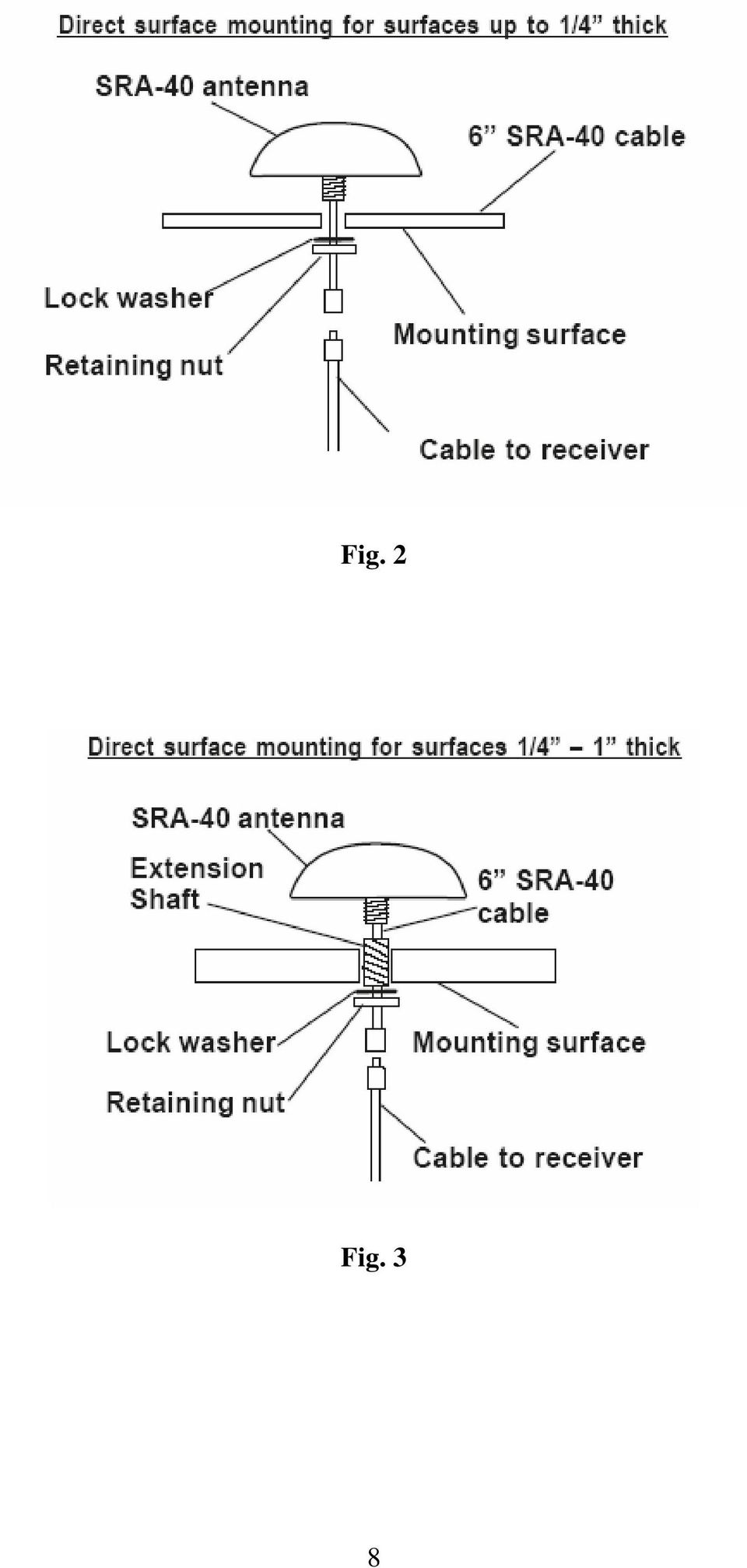
6 The power cable supplied is 10 ft [3m], however it can be extended up to 60 ft [see power cable installation]. The antenna cable supplied is 25 ft [7.6m], however alternative lengths can be ordered [35 ft, 50 ft, 90 ft and 135 ft. Be advised that the 135 ft cable comes with its own inline amplifier. Mounting the Antenna: The antenna can be installed as a standard pedestal mounting or surface mounting [non metallic surface only]. Depending on the method of mounting and thickness of mounting substrate, the hardware screws supplied may not be suitable. First determine the method of mounting to be used. For pedestal mounting it is required to drill both the 9/16 hole and the three 7/64 dia. holes. For the direct surface mount method, only the 9/16 dia. hole is required. Pedestal mounting: [see fig. 1] 1. Unscrew the base from the lower plastic body [note the O ring and retain]. 2. Use the rubber gasket or base as a template to mark the locations of the three mounting holes and the centre hole for passing through the short antenna cable with the connector. 3. Use the 9/16 drill bit for the centre hole and the 7/64 drill bit for the three fixing holes. 4. Thread the short cable and connector through the gasket and centre hole. 5. Mount the gasket and flange of the antenna using the supplied screws. 6. Attach the antenna base to the lower body plastic, making sure the O ring is in place. Surface mounting: [FOR NON METALIC SUBSTRATES ONLY]. See fig. 2 & fig. 3. There are two options available depending on location and mounting structure. 1. Up to ¼ thick mounting substrate. 2. ¼ 1 thick mounting substrate. For substrates up to ¼ thick - only the 9/16 dia. hole is required. 6
![Mounting the Antenna: The antenna can be installed as a standard pedestal mounting or surface mounting [non metallic surface only].](/docs-images/47/21008594/images/page_6.jpg "Depending on the method of mounting and thickness of mounting substrate, the hardware screws supplied may not be suitable. First determine the method of mounting to be used.")
7 1. Remove the lower plastic body of the antenna [not the mounting base] and pass the short cable with its connector through. 2. Seal the hole around the shaft passing through with a suitable weather sealer [not supplied] before installing the lock washer and nut supplied. For substrates between ¼ to 1 thick - only the 9/16 dia. hole is required. 1. As above, remove the lower plastic body of the antenna. 2. The extension shaft is now required to be attached to the threaded metallic post of the antenna, ensuring that the cable is first located in the slot of the threaded metallic post. 3. This assembly can now be passed through the 9/16 hole and as above, seal before installing the lock washer and nut. Fig. 1 7

8 Fig. 2 Fig. 3 8
9 Cable Installation: The power cable, as supplied is 10 ft [3m] long, however it may be extended to a maximum of 60 ft [20m] using a suitable 16 AWG multi stranded cable. Red is positive, black is negative. Should the shield wire of the power cable be required to be extended to reach the nearest ground point [RF ground preferred if installed on your vessel.] Use a 16 AWG multi strand wire. If your vessel does not have an RF system, connect the shield wire to the negative battery terminal. The antenna cable, as supplied is 25 ft [7.6m]. Should it not be sufficient for your installation, contact your dealer to obtain a suitable cable. The Ethernet cable, as supplied is 10 ft [3m] and is required to be connected between the receiver and an ethernet hub. If you are connecting the BBWX1 to a single Furuno VX2 processor / display, you must purchase an optional Furuno Navnet Ethernet Cross-over cable and hub adapter cable, and an RJ-45 inline coupler. Be advised that the hub, coupler and cross over cable are not supplied. GENERAL: All cables are to be secured properly over their entire length with no strain on any connector. Furthermore the minimum bend radius to be greater than 1 [25.4mm]. This applies when routing cables and/ or bundling excess cable. 9
![] Use a 16 AWG multi strand wire. If your vessel does not have an RF system, connect the shield wire to the negative battery terminal. The antenna cable, as supplied is 25 ft [7.6m].](/docs-images/47/21008594/images/page_9.jpg "Should it not be sufficient for your installation, contact your dealer to obtain a suitable cable.")
10 BBWX1 Receiver: Important REMINDER: Record both the Sirius Data and Audio Serial numbers as identified on the underside of your receiver before mounting. Orientation of the unit to be such that the connector panel is pointing down and receiver be mounted on a vertical face. A minimum of 6 [152mm] is required to be left below the connector panel to allow for adequate clearance for connections and cable bends. 1. Mark the location of the three fixing holes by using the unit as a template. 2. Drill through the marked positions using the #36 drill bit. 3. Mount the receiver using the three #6 x 5/8 lg type A, S/T screws supplied. * depending on thickness of substrate the holes may require enlarging. 10
![A minimum of 6 [152mm] is required to be left below the connector panel to allow for adequate clearance for connections and cable bends. 1.](/docs-images/47/21008594/images/page_10.jpg "Mark the location of the three fixing holes by using the unit as a template. 2. Drill through the marked positions using the #36 drill bit. 3.")
11 Typical system Diagrams: SRA-40 NavNet 6-Pin to 6-Pin Blue Network Cable and Hub Adapater Cable NavNet VX2 Display Ethernet Hub BBWX1 NavNet 6-Pin to 6-Pin Blue Network Cable and Hub Adapater Cable NavNet VX2 Display Dual Display / Processor SRA-40 To connect a single NavNet display to a BBWX1, use cable and an RJ-45 to RJ-45 Inline coupler, or use a standard NavNet Blue 6 pin to 6 pin network cable and a hub adapter cable ( ) with a cross-over RJ-45 to RJ-45 Inline Coupler. RJ-45 Straight Through Inline Coupler RJ4--5CN-STR meter 6 pin to RJ-45 Cable OR NavNet 6-Pin to 6-Pin Blue Network Cable and Hub Adapter Cable BBWX1 Ethernet Cable (std supply) NavNet VX2 Display RJ-45 Crossover Inline Coupler P/N RJ4-5CN-CRS BBWX1 Single Display / Processor (optional NavNet cable(s) and coupler required) 11
 NavNet")
12 Initial Activation: 1. Power the receiver and confirm solid red LED for approx. 1 minute. This is followed by a solid amber to flashing amber to solid green to finally a flashing green LED [additional 0.5 minutes]. At this point the software is fully loaded and system is ready. 2. Turn on your display [refer to your individual user guide/ handbook for detailed information]. 3. Contact Sirius to activate your system. ( ) Reminder: have your serial number available (Data ESN) which is marked on the underside of your receiver. Note: Should you see actual weather data displayed prior to activation, this is only the balance of the manufacturers [time limited activation which was used for testing purposes at the factory] and does not reflect that your personal activation is in place. Operation: 1. With the system and your display powered ON. 2. It may take up to 30 minutes before the system is populated with weather data. 3. Open a weather application page on your display and make it active. [For full details of how to carry this out, refer to the relevant display handbook supplied with your equipment.] 4. One of your first actions will be to locate and record your own personal Sirius ID number. 12
![Turn on your display [refer to your individual user guide/ handbook for detailed information]. 3. Contact Sirius to activate your system.](/docs-images/47/21008594/images/page_12.jpg "(1-800-869-5480) Reminder: have your serial number available (Data ESN) which is marked on the underside of your receiver.")
13 Troubleshooting. BBWX1 Diagnostics: 1. The following identifies the Key to the LED blinking pattern as depicted on the connector panel of the receiver. KEY. FAULT LED COLOR PATTERN Network disconnected: Amber 1 sec. ON 1 sec. OFF 1 sec. ON 2 sec. OFF Antenna disconnected: Amber 1 sec. ON 2 sec. OFF Both disconnected: Amber 1 sec. ON 1 sec. OFF 1 sec. ON 2 sec. OFF 1 sec. ON 2 sec. OFF System Ready: Green Flashing 13

14 GENERAL MAINTENANCE: Caution: Always turn your weather system OFF before carrying out routine maintenance. Your SDR is a sealed unit. DO NOT REMOVE the two end plates of the receiver. There are no user serviceable parts or adjustments inside. Any internal adjustments to be made must be carried out by an approved and qualified technician. Routine checks: Examine all cables for signs of damage. Check that all cables are supported. Check that all connectors are fully inserted and supported. Check that dust caps are located on the connector face [if no cable is available]. Cleaning: Wipe the module with a clean damp cloth. If necessary, Isopropyl Alcohol [IPA] or a mild detergent solution can be used to remove stubborn marks. 14

StructureScan HD Module. Installation Guide ENGLISH. www.bandg.com www.simrad-yachting.com www.lowrance.com
 StructureScan HD Module Installation Guide ENGLISH www.bandg.com www.simrad-yachting.com www.lowrance.com Disclaimer As Navico is continuously improving this product, we retain the right to make changes
Triac Printed Circuit Board Replacement
 Technical Service Bulletin: Triac Printed Circuit Board Replacement TRONIC 5000C Pro Models: WH17, WH27, WH36 Introduction Fig. 1 ELECTRICITY IS EXTREMELY DANGEROUS. TAKE EXTRA PRECAUTIONS AND ENSURE ALL
4.3-inch Back-Up Camera
 TM 4.-inch Back-Up Camera Model No.: PKC0BU4 Owner s Manual and Warranty Information Read these instructions completely before using this product. Retain this Owner s Manual for future reference. INTRODUCTION
INSTALLATION MANUAL. Installation Instructions
 INSTALLATION MANUAL Power-Pole Signature Series Shallow Water Anchor Installation Instructions CAUTION: Read this instruction manual carefully. Become familiar with the controls and know how to operate
Manual. Simrad StructureScan LSS-1 Sonar Module. English
 Manual Simrad StructureScan LSS-1 Sonar Module English www.simrad-yachting.com A brand by Navico - Leader in Marine Electronics Disclaimer As Navico is continuously improving this product, we retain the
Part Name/Description Part Number Quantity. Power Cable 4000950-5 1
 Note: Indented items indicate parts included in an assembly listed above Part Name/Description Part Number Quantity Power Cable 4000950-5 1 Raven Harness Adapter Kit 4100525 1 Installation Instructions
ELECTRONIC THERMOSTAT AND THERMOMETER With SPEED CONTROL
 148 OLD CONCORD TURNPIKE, BARRINGTON NH 03825 USA TEL (603) 868-5720 FAX (603) 868-1040 1-800-435-6708 E-Mail:sales@seafrost.com www.seafrost.com ELECTRONIC THERMOSTAT AND THERMOMETER With SPEED CONTROL
Home Signal Distribution Kit for Cable TV Plus SIRIUS
 Home Signal Distribution Kit for Cable TV Plus SIRIUS For Use With a Single SIRIUS Radio Installation Manual Thank you for purchasing the Home Signal Distribution Kit for Cable TV Plus SIRIUS The Home
Sealed Industrial Ethernet Circular IP67 Cat. 5e RJ45 Connector System
 Revised Sept--22-2009 Sealed Industrial Ethernet Circular IP67 Cat. 5e RJ45 Connector System Description The sealed circular RJ45 connector system is designed for use in harsh environments. The connector
Traditional Sonar and DSI Sonar Installation
 Traditional Sonar and DSI Sonar Installation This document covers the installation of the transducer and display unit installation, which includes connecting the unit to power and installing the unit on
INSTALLATION INSTRUCTIONS
 INSTALLATION INSTRUCTIONS Accessory Application Publications No. AII23628 2003 PILOT Issue Date MAY 2002 PARTS LIST Security System Kit (sold separately): P/N 08E51-S84-100 2 Remote controls Attachment
Post Mount Light Installation*
 Post Mount Light Installation* *For the general installation of most Post Mount Spotlights, many vehicles may need slight modifications to these instructions. You will need the following tools: High torque
Wiper Motor Marinco 2.5. Installation Instructions
 Wiper Motor Marinco 2.5 Installation Instructions Wiper Motor Marinco-2.5 The Marinco 2.5 Wiper Motor Offers the Following Features: Fully sealed base and housing which allows installation in outdoor wet
GPS AutoSteer System Installation Manual
 GPS AutoSteer System Installation Manual Supported Vehicles John Deere Sprayers 4720 4630 4730 4830 AutoTrac Ready PN: 602-0227-01-A LEGAL DISCLAIMER Note: Read and follow ALL instructions in this manual
Navico-Northstar 2kW JRC Radar Package, Scanner Cable Removal and Replacement
 Navico-Northstar 2kW JRC Radar Package, Scanner Cable Removal and Replacement This work instruction describes the methods and means for which to remove and reinstall optional scanner cable configurations
KEYLESS ENTRY UPGRADE SECURITY SYSTEM for 2004 TOYOTA HIGHLANDER
 KEYLESS ENTRY UPGRADE SECURITY SYSTEM for 2004 TOYOTA HIGHLANDER DEALER SERVICE AND INSTALLATION MANUAL KIT NO. 00016-30915 Contents PARTS LIST... 2 PARTS ILLUSTRATIONS... 2 VEHICLE PREPARATION... 3 INSTALLING
DTM04 TANK MONITOR DTM08 TANK MONITOR Dtm12 TANK MONITOR. Installation and Operation Manual
 DTM04 TANK MONITOR DTM08 TANK MONITOR Dtm12 TANK MONITOR Installation and Operation Manual 1 ENGLISH Safety Instructions 2 Features 2-3 Specifications 3 Installation 4-5 Wiring Diagrams 6-7 Warranty 8
RMK-9. Installation and Operation instructions. ENGLISH Date: 04-2013 Document number: 81351-1-EN 2013 Raymarine UK Limited
 RMK-9 Installation and Operation instructions ENGLISH Date: 04-203 Document number: 835--EN 203 Raymarine UK Limited ENGLISH Document number: 835- Date: 04-203 Handbook information This handbook contains
AM/FM ANTENNA KIT (TOUR-PAK MOUNT)
") -J077 REV. 008-0-0 AM/FM ANTENNA KIT (TOUR-PAK MOUNT) GENERAL Kit Number 7-98A Models For model fitment information, see the P&A Retail Catalog or the Parts and Accessories section of www.harley-davidson.com
-J077 REV. 008-0-0 AM/FM ANTENNA KIT (TOUR-PAK MOUNT) GENERAL Kit Number 7-98A Models For model fitment information, see the P&A Retail Catalog or the Parts and Accessories section of www.harley-davidson.com
GENUINE PARTS INSTALLATION INSTRUCTIONS
 GENUINE PARTS INSTALLATION INSTRUCTIONS DESCRIPTION: Illuminated Kick Plate APPLICATION: Rogue (2011) PART NUMBER: 999G6 GX010 KIT CONTENTS: Item A B C G H QTY 1 1 1 D 1 E 1 F 3 15 6 Description Kick Plate,
OPL BASIC. Dosing System for Professional Laundry machines. Contents
 OPL BASIC Dosing System for Professional Laundry machines Contents 1 Getting Started. Page 2 2 Installation. Page 4 3 Set Up & Operation. Page 8 4 Maintenance & Accessories. Page 10 5 Troubleshooting Page
Before installation it is important to know what parts you have and what the capabilities of these parts are.
 INSTALLATION GUIDE Before installation it is important to know what parts you have and what the capabilities of these parts are. The Recon XZT is the smallest and most powerful gauge of its kind. With
2003/2004/2005 TOYOTA COROLLA
 2003/2004/2005 TOYOTA COROLLA KEYLESS ENTRY UPGRADE SECURITY SYSTEM INSTALLATION INSTRUCTIONS KIT NO. 00016-30120 SPECIAL NOTE: Installation Sequences After TMS and Safety mandated preparatory steps have
MCR1900 Media Converter 19-Slot Chassis
 MCR1900 Media Converter 19-Slot Chassis Installation Guide Part #5500304-11 Copyright Statement This document must not be reproduced in any way whatsoever, either printed or electronically, without the
SmartCard On-Board Reader (# 8105) SmartCard Desktop Reader (# 8108) SmartCards, Pack of 10 (# 8112) Starter Interrupter Kit (# 8116)
 SmartCard Desktop Reader (# 8108) SmartCards, Pack of 10 (# 8112) Starter Interrupter Kit (# 8116)") athena Includes: SmartCard On-Board Reader (# 8105) SmartCard Desktop Reader (# 8108) SmartCards, Pack of 10 (# 8112) Starter Interrupter Kit (# 8116) Davis Instruments, 3465 Diablo Avenue, Hayward, CA
athena Includes: SmartCard On-Board Reader (# 8105) SmartCard Desktop Reader (# 8108) SmartCards, Pack of 10 (# 8112) Starter Interrupter Kit (# 8116) Davis Instruments, 3465 Diablo Avenue, Hayward, CA
Document number RS-PRD-00130 Revision 05 Date 20/10/2009 Page 1/30
 Date 20/10/2009 Page 1/30 1. Purpose This document describes the field replacement of the footscan plate cable for these models: 2m hi-end plate SN 11/5/xxx 2m pro plate SN 7/5/xxx 0.5m 2003 hi-end plate
SCREENLOGIC INTERFACE WIRELESS CONNECTION KIT
 SCREENLOGIC INTERFACE WIRELESS CONNECTION KIT FOR INTELLITOUCH AND EASYTOUCH CONTROL SYSTEMS INSTALLATION GUIDE IMPORTANT SAFETY INSTRUCTIONS READ AND FOLLOW ALL INSTRUCTIONS SAVE THESE INSTRUCTIONS Technical
Roof Top Air Conditioner INSTALLATION AND OPERATING INSTRUCTIONS
 Roof Top Air Conditioner INSTALLATION AND OPERATING INSTRUCTIONS Ducted System RECORD THIS UNIT INFORMATION FOR FUTURE REFERENCE: Model Number: Serial Number: Date Purchased: This manual must be read and
DirectCommand Installation DirectCommand 3-Channel Spreader Kit
 Note: Indented items indicate parts included in an assembly listed above Part Name/Description Part Number With Switch Box Quantity With Remote Switch Display Cable Kit 4100814 1 1 Power Control Relay
Networkfleet 3500 Product Line Installation Guide
 Networkfleet 3500 Product Line Installation Guide Light/Medium Duty (L3500) Heavy Duty (H3500) Universal (U3500) www.networkcar.com/fleet Customer Care: (866) 227-7323 customercare@networkcar.com Table
Time needed: ~3h for lid replacement only. Add 1h for operation harness in lid and ~2h more for installing drive unit and cable harness in trunk.
 DIY for replacing trunk lid and/or retrofitting electrical operation of trunk lid. This document is meant to be a support and give advice on the procedure but I will take no responsibility for any damage
ScreenLogic Wireless Connection Kit. Installation Guide. pool/spa control system
 pool/spa control system ScreenLogic Wireless Connection Kit Installation Guide P/N 520663 - Rev B 8 Technical Support Contact Technical Support at: Sanford, North Carolina (8 A.M. to 5 P.M.) Phone: (800)
Model 201 Wiegand Touchpad Reader Installation Guide
 Model 201 Wiegand Touchpad Reader Installation Guide P/N 460353001C 15AUG11 2011 UTC Fire & Security. All rights reserved. This document may not be copied in whole or in part or otherwise reproduced without
5800 Temperature Sensor Cable Assembly
 5800 Temperature Sensor Cable Assembly Removal and Replacement Instruction Sheet #60-4702-070 Revision D, January 14, 2013 Overview The 5800 has two refrigeration temperature sensors, one attached to the
AM/FM ANTENNA RELOCATION KIT
 -J0 REV. 008-09-0 AM/FM ANTENNA RELOCATION KIT GENERAL Kit Number 766-09 Models This kit is used to relocate a fender-mounted AM/FM antenna to a Detachable Tour-Pak on specific model motorcycles. For model
INSTRUCTIONS FOR THE INSTALLATION AND OPERATION OF ACTIVATOR II
 INSTRUCTIONS FOR THE INSTALLATION AND OPERATION OF ACTIVATOR II ELECTRONIC TRAILER BRAKE CONTROL 5500 FOR 2, 4, 6 & 8 BRAKE SYSTEMS IMPORTANT: READ AND FOLLOW THESE INSTRUCTIONS CAREFULLY. KEEP THESE INSTRUCTIONS
Range Road RR Series Semi-Automatic Firewood Processor. Crated Unit Assembly Manual
 Range Road RR Series Semi-Automatic Firewood Processor Crated Unit Assembly Manual 1 1) Undo 8-18mm x 19mm Nuts and bolts, 2 on each leg of top frame 2) Lift top of Metal crate off and move out of work
ELECTRONICS G H I J K L M
 ELECTRONICS TM LASER INSTALLATION INSTRUCTIONS PARTS KIT Parts Kit includes the following: A- (1) Universal Mounting Bracket A B- (1) Red L.E.D. Laser Alert Light C- (1) Piezo Beeper w/ O Ring Tape D-
EZ-Steer Assisted Steering System
 EZ-Steer Assisted Steering System Installation Instructions Platform Kit P/N 53059-21 Case IH Puma 165 Puma 180 Puma 195 Puma 210 New Holland T7030 T7040 T7050 T7060 Revision A June 2007 Part Number 53345-21-EU2
INSTALLATION AND OPERATING INSTRUCTIONS For Model GL1 Gate Locks
 Securitron Magnalock Corp. www.securitron.com ASSA ABLOY, the global leader Tel 800.624.5625 techsupport@securitron.com in door opening solutions INSTALLATION AND OPERATING INSTRUCTIONS For Model GL1 Gate
http://waterheatertimer.org/troubleshoot-rheem-tankless-water-heater.html
 http://waterheatertimer.org/troubleshoot-rheem-tankless-water-heater.html TECHNICAL SERVICE DEPARTMENT Removal, Cleaning, & Reinstallation of the Burner Assembly For models 74 & GT199 Required tools -
Cooktop Low-Profile Ventilation Hoods
 INSTALLATION GUIDE Cooktop Low-Profile Ventilation Hoods Contents Wolf Cooktop Low-Profile Ventilation Hoods........ 3 Cooktop Low-Profile Hood Specifications.......... 4 Cooktop Low-Profile Hood Installation............
Home Signal Distribution Kit for Satellite TV Plus SIRIUS
 SR-101C SIRIUS/DBS Signal Combiner System SR-2261 Combiner-Outdoor Made in China DBS IN SIRIUS IN SR-101C SIRIUS/DBS Signal Combiner System SR-2251 Splitter-Indoor Made in China DC IN DBS OUT SIRIUS OUT
12 Volt 30 Amp Digital Solar Charge Controller
 12 Volt 30 Amp Digital Solar Charge Controller User s Manual WARNING Read carefully and understand all INSTRUCTIONS before operating. Failure to follow the safety rules and other basic safety precautions
Draper Low Voltage, Remote Control, Serial and Network Wiring Guide
 Draper Low Voltage, Remote Control, Serial and Network Wiring Guide Copyright 2007 Draper Inc. Form LV-RC-Serial-Network_Wiring07 Print ed in U.S.A. Draper Low Voltage, Remote Control, Serial and Network
Digital Fingerprint safe
 Digital Fingerprint safe Model 96846 Operation Instructions Diagrams within this manual may not be drawn proportionally. Due to continuing improvements, actual product may differ slightly from the product
Replacing a Vantage Vue Transmitter
 Replacing a Vantage Vue Transmitter Included in this replacement transmitter kit: SIM transmitter Cable tray Instructions Tools Required Phillips head screwdriver Small pliers To replace the transmitter
Universal Vehicle Power Supply 9007AX01. Installation Instructions
 Universal Vehicle Power Supply 9007AX01 Installation Instructions Disclaimer Honeywell International Inc. ( HII ) reserves the right to make changes in specifications and other information contained in
Installation Instructions 4508 4508S
 SYMPHONY Spread Lavatory Faucet with Speed Connect Drain Congratulations on purchasing your American Standard faucet with Speed Connect drain, a feature found only on American Standard faucets. Speed Connect
Guide for Installation and Maintenance of MacroAir (ME Series) High Volume Low Speed Fans
 High Volume Low Speed Fans") Guide for Installation and Maintenance of MacroAir (ME Series) High Volume Low Speed Fans Version 9.0 April 2014 1 Delivery: Upon receipt of fans, thoroughly inspect units for any damage sustained during
Guide for Installation and Maintenance of MacroAir (ME Series) High Volume Low Speed Fans Version 9.0 April 2014 1 Delivery: Upon receipt of fans, thoroughly inspect units for any damage sustained during
Installation Instructions Avalanche XUV Cap IMPORTANT! IMPORTANT!
 Installation Instructions Avalanche XUV Cap IMPORTANT! Read all instructions carefully before commencing any work. Always wear safety equipment. Some installation steps will require two or more installers.
ReachFree ID Installation Instructions For Portal TI, Sentinel and C-Start. Unitec www.startwithunitec.com
 ReachFree ID Installation Instructions For Portal TI, Sentinel and C-Start Unitec www.startwithunitec.com Proprietary Information and Materials of Unitec, Inc. Such proprietary information and materials
RAY-MAX Integrated Solar Power Strip
 RAY-MAX Integrated Solar Power Strip 600008, 600009, 600010, 600208, 600209, 600210 Owner s Manual NEXTRONEX, INC. Revision Date: 10/27/14 Contents 1. Safety Instructions... 3 2. General Equipment Warnings...
IntelliChlor Flow-Temperature Switch Replacement Kit Installation Guide
 IntelliChlor Flow-Temperature Switch Replacement Kit Installation Guide Technical Support Sanford, North Carolina (8 A.M. to 5 P.M.) Moorpark, California (8 A.M. to 5 P.M.) Phone: (800) 831-7133 Fax: (800)
WARNING! REQUIRED TOOLS & SUPPLIES: HIGH VOLTAGE
 INSTRUCTIONS Product: GEM Electric Motorcars Models: All Subject: Instructions for installing Stereo Accessory Estimated Completion Time:.75 Hours Parts: See Page # 7 REQUIRED TOOLS & SUPPLIES: (1) 3/8
UB1 AIR CONDITIONING UNIT INSTALLATION INSTRUCTIONS
 UB1 AIR CONDITIONING UNIT INSTALLATION INSTRUCTIONS INSTALLATION INSTRUCTIONS: Carefully read these instructions before installing your new air-conditioner. AUSTRALIAN AUTOMOTIVE AIR AL00500054E 1 Table
Cisco Aironet 2.4-GHz MIMO Wall-Mounted Omnidirectional Antenna (AIR-ANT2440NV-R)
") Cisco Aironet 2.4-GHz MIMO Wall-Mounted Omnidirectional Antenna (AIR-ANT2440NV-R) This document outlines the specifications for the Cisco Aironet 2.4-GHz MIMO Wall-Mounted Omnidirectional Antenna (AIR-ANT2440NV-R)
Cisco Aironet 2.4-GHz MIMO Wall-Mounted Omnidirectional Antenna (AIR-ANT2440NV-R) This document outlines the specifications for the Cisco Aironet 2.4-GHz MIMO Wall-Mounted Omnidirectional Antenna (AIR-ANT2440NV-R)
LIEBERT VNSA Installation Sheet
 LIEBERT VNSA Installation Sheet Description The Liebert vnsa network switch is designed for connecting multiple Ethernet-ready devices and comes in various models. The unit may have: A Liebert icom display
CortezTM A Kichler Décor Ceiling Fan
 CortezTM A Kichler Décor Ceiling Fan Kichler Lighting 7711 East Pleasant Valley Road P.O. Box 318010 Cleveland, Ohio 44131-8010 Customer Service 866.558.5706 8:30 AM to 5:00 PM EST, Monday - Friday Instruction
StructureScan Installation
 StructureScan Installation Contents Your StructureScan box is packed with the LSS-1 black box, a Power cable, StructureScan transducer, mounting bracket, 15 foot (4.5m) ethernet cable and a hardware kit.
1. SAFETY RULES WARNING TO REDUCE THE RISK OF FIRE, ELECTRIC SHOCK OR PERSONAL INJURY, MOUNT FAN TO OUTLET BOX MARKED "ACCEPTABLE FOR FAN SUPPORT".
 1 1. SAFETY RULES 1. To reduce the risk of electric shock, insure electricity has been turned off at the circuit breaker or fuse box before beginning. 2. All wiring must be in accordance with the National
VHF 100/200 Series Radio Installation Instructions
 VHF 100/200 Series Radio Installation Instructions These installation instructions are for the following VHF radios and handsets: North American Models VHF 100 VHF 200 GHS 10 International Models VHF 100i
HARTING Ethernet Cabling 4-poles Overview
 Ethernet Cabling 4-poles Overview RJ45 Connectors [on page 8] System cables [on page 10] Distribution modules and Outlets [on page 20] Connectors [on page 22] System cables [on page 24] Panel feed-throughs
Detector transparent with Color Inserts. FAA 500 TR P Trim Ring transparent with Color Inserts. FCA 500 / FCA 500 E Detector Bases
 Detector Color Detector transparent with Color Inserts FAA 500 TR W Trim Ring FAA 500 TR P Trim Ring transparent with Color Inserts FAA 500 BB Ceiling Mount Back Box FCA 500 / FCA 500 E Detector Bases
TOOL SVC NUMBERS: 250-2598, 250-2600 SVC CONTENTS ITEM QTY DESCRIPTION PART NUMBER 1 1 CUTTING TOOL 250-2598 2 1 EXTRACTION TOOL/PART# 250-2600
 07-08 TOYOTA FJ CRUISER, 05-09 SIENNA, 06-08 SCION TC PART NUMBER: 250-1732 1 CRUISE CONTROL KIT TOOL SVC NUMBERS: 250-2598, 250-2600 2 2 1 BASE KIT CONTENTS ITEM QTY DESCRIPTION 1 1 CONTROL SWITCH ASSEMBLY
Owners & Installation Manual for the Sheridan, Mountainair, Pine Valley and Old Forge Ceiling Fan Family
 Owners & Installation Manual for the Sheridan, Mountainair, Pine Valley and Old Forge Ceiling Fan Family Part of the Kiva Lighting Family Custom Lighting and Fans Since 1992 1312 12th St NW Albuquerque,
INSTALLATION INSTRUCTIONS
 INSTALLATION INSTRUCTIONS Application Outboards Faria 5 Gauge Set* Publication No. Description Part Number Honda Code PII53606A White faced, flat lens 06300-ZW5-010ZB 6315410 Issue Date Black faced, flat
GSD 22 Sounder Module. installation instructions
 GSD 22 Sounder Module installation instructions Copyright 2006 Garmin Ltd. or its subsidiaries Garmin International, Inc. 1200 East 151 st Street, Olathe, Kansas 66062, USA Tel. (913) 397.8200 or (800)
A&A CORVETTE PERFORMANCE C6 BOOST & FUEL GAUGE INSTALLATION INSTRUCTIONS
 A&A CORVETTE PERFORMANCE C6 BOOST & FUEL GAUGE INSTALLATION INSTRUCTIONS 1. Check your gauges before you take them out of the packaging to make sure they are at 0 (zero) psi for both boost and fuel pressure.
Mini USB and USB 2.0-IP67 Connector System
 Mini USB and USB 2.0-IP67 Connector System Section 12 Mini USB and USB 2.0-IP67 Connector System CONEC has added the Mini-USB connector. This Mini-USB IP67 receptacle and plug family, feature a bayonet
Upgrading a GainMaker Line Extender from a Line-Powered Source to a 120 V AC-Powered Source Installation Instructions
 Upgrading a GainMaker Line Extender from a Line-Powered Source to a 120 V AC-Powered Source Installation Instructions Overview Audience These installation instructions are intended for all cable system
CUSTOM AUXILIARY FORWARD LIGHTING KIT
 -J0 REV. 0--0 CUSTOM AUXILIARY FORWARD LIGHTING KIT GENERAL Kit Number -0, 0000 Models This Custom Auxiliary Lighting Kit adds lamps and turn signals to 00 and later FLHX model motorcycles. Additional
TraceTek TTDM Series Leak Detection and Location Modules Replacement Parts Installation Instructions
 TraceTek TTDM Series Leak Detection and Location Modules Replacement Parts Installation Instructions TRACETEK TraceTek TTDM Replacement Parts General Information These instructions detail the steps to
EZ-Steer Assisted Steering System
 EZ-Steer Assisted Steering System Installation Instructions Platform Kit P/N 53059-54 Case IH CVX 1135 CVX 1145 CVX 1155 CVX 1170 CVX 1190 CVX 1195 CVX 135 CVX 145 CVX 155 CVX 175 CVX 195 New Holland TVT
1. SAFETY RULES. 8. Avoid placing objects in the path of the blades.
 1 1. SAFETY RULES 1. To reduce the risk of electric shock, insure electricity has been turned off at the circuit breaker or fuse box before beginning. 2. All wiring must be in accordance with the National
WARNING: FAILURE TO FOLLOW THESE RULES MAY RESULT IN SERIOUS PERSONAL INJURY CAUTION: INSTALLATION LOCATION:
 Revision Level: 01 Revision Date: 07/07/2011 Please read all instructions carefully to help ensure a correct and SAFE installation of your Second Wind Ultraviolet Germicidal Air Purifier. Failure to do
HARTING Ethernet Cabling 8-poles Overview
 Ethernet Cabling 8-poles Overview RJ45 Connectors [on page 8] System cables [on page 12] Distribution modules and Outlets [on page 17] Connectors [on page 20] System cables [on page 26] Panel feed-throughs
Table of Contents. www.hunterfan.com. What to Expect with. Preparation. Tools Needed. Wiring. Hanging the Fan. Blades. Motor Housing.
 www.hunterfan.com Table of Contents What to Expect with Your Installation 30 inches Hanging the Fan Wiring 8 Maintenance, Operation & Cleaning Light Kit 13??? 14 1 9 Troubleshooting 11 5 Blades Motor Housing
CHARGING SYSTEMS INTERNATIONAL
 CHARGING SYSTEMS INTERNATIONAL INSTALLATION AND OPERATING INSTRUCTIONS FOR THE FOLLOWING BATTERY CHARGING SYSTEMS: MODELS MAX AMPS/BANK NO. OF BANKS BATTERY SYSTEM PRO XL 6 1 12 DUAL PRO XL 6 2 12/24 PRO
specializing in AIR CONDITIONING, PARTS AND SYSTEMS for your classic vehicle PERFECT FIT IN-DASH HEAT/ COOL/ DEFROST 1967-72 CHEVROLET PICKUP
 specializing in AIR CONDITIONING, PARTS AND SYSTEMS for your classic vehicle PERFECT FIT IN-DASH HEAT/ COOL/ DEFROST 1967-72 CHEVROLET PICKUP CONTROL & OPERATING INSTRUCTIONS The controls on your new Perfect
Installation Instructions 6028.801
 DAZZLE Installation Instructions 08.80 Spread Lavatory Faucet with Speed Connect Drain* Congratulations on purchasing your American Standard faucet with Speed Connect drain, a feature found only on American
ADDENDUM USER MANUAL LBV300S-6, LBV300XL & LBV600XL
 ADDENDUM USER MANUAL LBV300S-6, LBV300XL & LBV600XL DOCS-004 Rev C The information, photographs, illustrations and descriptions contained in this manual are the property of SeaBotix Inc. Unauthorized duplication
2M IR Mini Dome Quick Installation Guide
 2M IR Mini Dome 2M IR Mini Dome Quick Installation Guide Please follow the installation steps below to set up 2M IR Mini Dome IP Camera. Check the package contents against the list below. See P.1 Physical
20000068 WIRELESS REMOTE ASSEMBLY, 24VDC, 1 TRANS,1 REC
 20000068 WIRELESS REMOTE ASSEMBLY, 24VDC, 1 TRANS,1 REC Fitment to MP-25 620 CR 4841, Haslet, TX 76052 Ph 817.439.1108 Fax 817.636.5675 www.machine-technologies.com Kit contents 1 Transmitter 2 button,
Amps Per Bank. Total Output. Battery System. Model Name. 6 amps 12 amps 10 amps 20 amps 30 amps 40 amps 15 amps 30 amps 45 amps
 Model Name Total Output Amps Per Bank Battery System Pro XL Dual Pro XL Pro SE Dual Pro SE Three Bank Pro SE Four Bank Pro SE Pro Charger Dual Pro Charger Three Bank Pro Charger 6 amps 12 amps 10 amps
P150SC15. Designed for 2015 Ford F150 Super-Cab and Super-Crew vehicles without Sony System. 2015 Stillwater Designs P150SC15-A2-20150813
 P150SC15 Designed for 2015 Ford F150 Super-Cab and Super-Crew vehicles without Sony System Subwoofer Assembly Amplifier Assembly Amplifier Harness 2015 Stillwater Designs P150SC15-A2-20150813 M6 Bolt M6
TOYOTA TACOMA 2008- HANDS FREE BLU LOGIC Preparation
 TOYOTA TACOMA 2008- HANDS FREE BLU LOGIC Preparation Part #: PT923-00112 Conflicts: JBL Audio, Factory Navigation NOTE: Part number of this accessory may not be the same as the part number shown. Kit Contents:
TOYOTA Tundra 2007 - BACK-UP CAMERA SYSTEM Preparation
 Preparation Part Number(s): PT233-34070, PT923-35070-11, PT923-35070-43 NOTE: Part number of this accessory may not be the same as part number shown. Back Up Monitor Kit Contents PT923-35070-11 / PT923-35070-43
Toroidal Conductivity Sensor
 Instruction Sheet PN 51A-/rev.C June 2012 Toroidal Conductivity Sensor For additional information, please visit our website at www.emersonprocess.com/rosemountanalytical.com SPECIFICATIONS Wetted Materials:
Step 1. Item 6. Item 1
 Voltage Regulators QD3/T350 Motor Replacement Kit Kit Number 57A63675100B Service Information S225-50-35 Contents General..................................... 1 Parts Supplied...............................
Raystar 125 GPS Receiver Owner's Handbook
 Raystar 125 GPS Receiver Owner's Handbook 1 www.raymarine.com Welcome to the Raystar RS125 GPS Receiver Your handbook contains an explanation of how to install, operate and maintain your Raystar RS125
GENUINE PARTS INSTALLATION INSTRUCTIONS
 GENUINE PARTS INSTALLATION INSTRUCTIONS 1. DESCRIPTION: Auto-Dimming Mirror Kit with Compass and HomeLink 2. APPLICATION: Titan 3. PART NUMBER: 999L1 WS000 4. KIT CONTENTS: Item Qty Description Service
Oceanscience Cable Chimp II Cableway ROV System User Guide and Warranty
 Oceanscience Cable Chimp II Cableway ROV System User Guide and Warranty Page 1 Table of Contents Introduction Page 3 Overview Page 3 Setup and Operation Page 5 Remote Control Page 6 Power Management Page
Arecont Vision H.264 Color or Day/Night SurroundVideo Series Installation Manual
 0 P a g e H.264 Color or Day/Night SurroundVideo Installation Manual Inside the box: A. Arecont Vision SurroundVideo camera B. Mounting template C. RJ45 female to female coupler D. Hex key E. Security
HG600/HG800. Hydro-Power Unit. Installation and Operation Guide
 HG600/HG800 Hydro-Power Unit Installation and Operation Guide Copyright 04 HydroSpin, All rights reserved. The data contained in this document is proprietary to HydroSpin. It is disclosed to the receiving
E-PDD Duct Smoke Detector Installation Sheet
 E-PDD Duct Smoke Installation Sheet Operation The duct smoke detector's primary purpose is to provide early warning of an impending fire and shut down the HVAC unit in order to prevent smoke from circulating
The Fan-Aspirated ISS includes these components: Metric Rain Adapter. The hardware shown here is provided for assembly and mounting:
 Integrated Sensor Suite with Fan-Aspirated Radiation Shield Installation Instructions Addendum For Vantage Pro2 and Vantage Pro2 Plus The Vantage Pro2 Integrated Sensor Suite (ISS) with the Fan-Aspirated
Installation & Weatherproofing Guide for ENCOM Broadband Radios
 Installation & Weatherproofing Guide for ENCOM Broadband Radios Read the following instructions before proceeding with your ENCOM Wireless Radio installation. Keep these instructions in safe location for
RECOMMENDED TOOLS PERSONAL & VEHICLE PROTECTION SAFETY GLASSES
 PART NUMBER: 250-9612 GENERAL APPLICABILITY THIS CRUISE WAS TESTED AND VERIFIED ON: FORD FOCUS SE & S MODELS (AT/MT) FORD TRANSIT ALL MODELS RECOMMENDED TOOLS PERSONAL & VEHICLE PROTECTION SAFETY GLASSES
SB-C-CTS/10TW3 SKU# 94552 2008 & Up Cadillac CTS/CTS-V
 INSTALLATION GUIDE for the SB-C-CTS/10TW3 SKU# 94552 2008 & Up Cadillac CTS/CTS-V If you choose to perform the installation yourself, it is absolutely vital that the Stealthbox be properly mounted to the