C13 User Manual Document ID: 2CMC486004M0201 Revision: A
|
|
|
- Franklin Long
- 7 years ago
- Views:
Transcription
1 C13
2

3 C13 Document ID: 2CMC486004M

4 Disclaimer Copyrights Trademarks Contact The information in this document is subject to change without notice and should not be construed as a commitment by ABB AB. ABB AB assumes no responsibility for any errors that may appear in this document. In no event shall ABB AB be liable for direct, indirect, special, incidental or consequential damages of any nature or kind arising from the use of this document, nor shall ABB AB be liable for incidental or consequential damages arising from use of any software or hardware described in this document. This document and parts thereof must not be reproduced or copied without written permission from ABB AB, and the contents thereof must not be imparted to a third party nor used for any unauthorized purpose. The software or hardware described in this document is furnished under a license and may be used, copied, or disclosed only in accordance with the terms of such license. Copyright 2013 ABB AB. All rights reserved. ABB AB is a registered trademark of the ABB Group. All other brand or product names mentioned in this document may be trademarks or registered trademarks of their respective holders. ABB AB P.O. BOX 1005 SE NYKÖPING SWEDEN Tel: Fax:

5 1 About this Manual Conventions Used in this Document Product Overview Meter Parts Meter Type Installation Mounting the Meter Environmental Considerations Installing the Meter Wiring Diagrams Outputs User Interface Display and buttons Menu Structure Meter Settings Setting the Output Setting the Alarm Technical Description Energy Values Instrumentation Outputs Alarm Technical data Technical Specifications Physical Dimensions Troubleshooting Error Codes and Warnings Service & Maintenance Service and Maintenance CMC486004M C13

6 C13 2 2CMC486004M0201

7 About this Manual Chapter 1: About this Manual Overview This chapter describes the conventions used in this manual. It also contains explanations and definitions of terms and definitions that are used in the document. In this chapter The following topics are covered in this chapter: 1.1 Conventions Used in this Document CMC486004M C13

8 About this Manual 1.1 Conventions Used in this Document Symbols This document contains warning, caution, note and tip icons that point out safety related conditions and other important or useful information. Symbol Description The electrical warning icon indicates the presence of a hazard which could result in electrical shock. The caution icon indicates important information or a warning related to the concept discussed in the text. It might indicate the presence of a hazard which could result in corruption of software or damage to equipment or property. The note icon alerts the reader to important facts and conditions. The tip icon gives the reader useful information related to the concept discussed in the text. C13 4 2CMC486004M0201

9 Product Overview Chapter 2: Product Overview Overview This chapter describes the parts of the meter. It also contains information about the meter type. In this chapter The following topics are covered in this chapter: 2.1 Meter Parts Meter Type CMC486004M C13

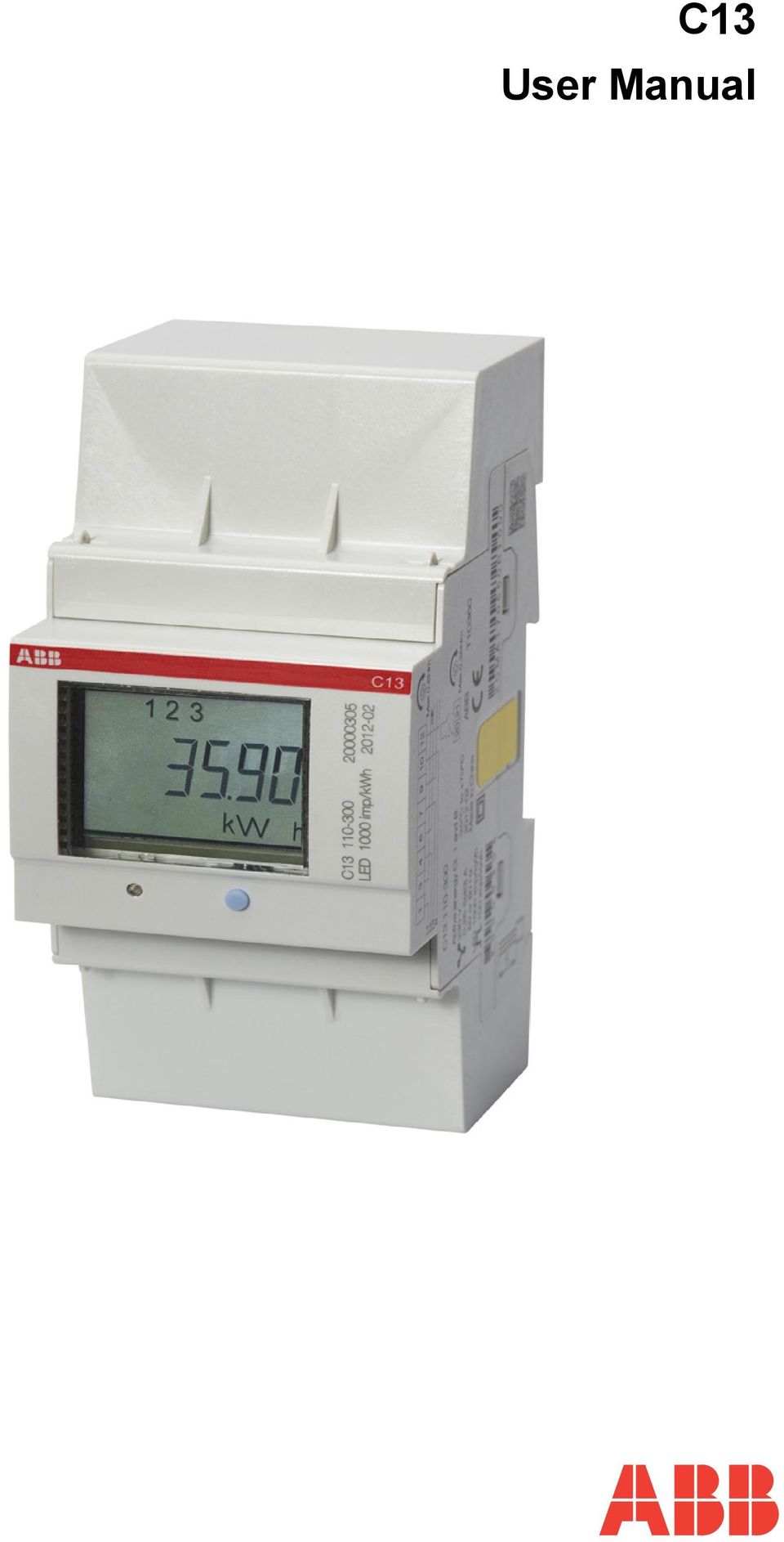
10 Product Overview 2.1 Meter Parts Illustration The parts of the meter are shown in the illustration below: Parts description The following table describes the parts of the meter: Item Description Comments 1 Terminal for output connections 2 Sealing points 3 Push button For programming and reading metering data 4 LED Flashes in proportion to the energy measured 5 Display LCD for meter reading 6 Sealing label 7 Product data 8 Terminal block C13 6 2CMC486004M0201

11 Product Overview 2.2 Meter Type C13 meter The C13 is a compact meter for 3-phase metering. The meter is direct connected for currents up to max. 40 A. Product label The meter type information that is reflected on the product label is shown in the example picture below: Label information The information on the type label is explained in the table below: Item Description 1 Type designation 2 LED pulse frequency 3 Serial number 4 Manufacturing date (year and week) 5 Wiring diagram 6 Bar code with serial number 7 Type designation 8 Energy import 9 Accuracy (active energy) 10 Nominal voltage 11 3-element metering 2CMC486004M C13
 10 Nominal voltage 11 3-element metering")
12 Product Overview Item 12 Frequency 13 LED pulse frequency 14 Pulse frequency 15 Protection class II 16 Operating temperature range 17 Rated current 18 ABB ID Description C13 8 2CMC486004M0201

13 Installation Chapter 3: Installation Overview This chapter describes how to mount the C13 meter and how to connect it to an electricity network. In this chapter 3.1 Mounting the Meter Environmental Considerations Installing the Meter Wiring Diagrams CMC486004M C13

14 Installation 3.1 Mounting the Meter General This section describes different ways to mount the C13 meter. For some methods of mounting, additional accessories are needed. For further information about accessories, refer to Main Catalog (2CMC481003C0201). DIN-rail mounted The C13 meters are intended to be mounted on a standard (DIN 50022) DIN-rail. If this method of mounting is used no extra accessories are needed and the meter is fastened on the rail by snapping the DIN-rail lock onto the rail. Wall mounted The recommended way to mount the meter on a wall is to mount a separate DINrail on the wall and then mount the meter on the rail. Standard DIN-rail The following picture shows a standard DIN-rail. C CMC486004M0201

15 Installation 3.2 Environmental Considerations Ingress protection To comply with the protection requirements the product must be mounted in protection class IP 51 enclosures, or better, according to IEC Mechanical environment In accordance with the Measuring Directive (2004/22/EC), the product complies with M1, which means that it can be operated in...locations with vibration and shocks of low significance, e.g. for instruments fastened to light suporting structures subject to negligible vibrations and shocks transmitted from local blasting or pile-driving activities, slamming doors, etc. Electromagnetic environment In accordance with the Measuring Directive (2004/22/EC), the product complies with E2, which means that it can be operated...in locations with electro magnetic disturbances corresponding to those likely to be found in other industrial buildings. Climatic environment In order to work properly the product should not be operated outside the specified temperature range of -40 C +70 C. In order to work properly the product should not exposed to humidity exceeding the specified 75% yearly average, 95% on 30 days/year. 2CMC486004M C13

16 Installation 3.3 Installing the Meter E Warning E Warning E Warning Electrical equipment should only be installed, accessed, serviced and maintained by qualified electrical personnel. Working with high voltage is potentially lethal. Persons subjected to high voltage may suffer cardiac arrest, burn injuries, or other severe injuries. To avoid such injuries, make sure to disconnect the power supply before you start the installation. For safety reasons it is recommended that the equipment is installed in a way that makes it impossible to reach or touch the terminal blocks by accident. The best way to make a safe installation is to install the unit in an enclosure. Further, access to the equipment should be limited through use of lock and key, controlled by qualified electrical personnel. The meters must always be protected by fuses on the incoming side. In order to allow for maintenance of transformer rated meters, it is recommended that there should be a short circuiting device installed near the meter. Installation requirements To comply with the protection requirements the meter must be mounted in protection class IP 51 enclosures, or better, according to IEC Meters with wireless communication should not be installed closer than 20 cm from people. Install the meter Follow the steps in the table below to install the meter: Step Action 1 Switch off the mains power. 2 Place the meter on the DIN-rail and make sure it snaps onto it. 3 Strip the cable insulation to the length that is indicated on the meter. 4 Connect the cables according to the wiring diagram that is printed on the meter and tighten the screws (0.8 Nm). 5 Install the circuit protection (max 40 A). 6 Connect the output to an external power supply (max 5 40 V). See the wiring diagram printed on the meter. 7 Turn on the mains power. Verify the installation The C13 meter has a red LED next to the push button on the front of the meter that flashes proportionally to the active energy. The LED has a fixed pulse frequency of 1000 imp/kwh and can be used to test and verify the installation. If the LED flashes when the mains power is turned on, the installation was successful. C CMC486004M0201

17 Installation Wiring Diagrams 4-wire connection The following diagram shows a 4-wire connection of a direct connected 3-phase meter: Outputs Fixed, 1 output 2CMC486004M C13

18 Installation C CMC486004M0201

19 User Interface Chapter 4: User Interface Overview This chapter gives an overview of the display and of the functions of the button on the meter. In this chapter The following topics are covered in this chapter: 4.1 Display and buttons Menu Structure CMC486004M C13

20 User Interface 4.1 Display and buttons Display The display consists of icons, digits and letters. The measured value/menu options are displayed with large letters. The measured unit is displayed on the bottomright side of the display, and the status icons are displayed at the upper part of the display, see figure below. 123 k Arh Status Icons The status icons are shown in the table below. Icon Indication Comment Active error When a error has been detected, the icon will be lit on the display.! When no error has been detected, the icon will be turned off. Metering in progress. When a load is connected to the meter, the icon will flash to indicate metering. When no load is connected, the icon will be turned off. Button The meter has one push button which is located below the display. A short press on the button (less than 1 sec) will step through the menu/submenu. A long press (more than 1 sec) followed by a release of the button will open the set menu or select an item in the menu. C CMC486004M0201

21 User Interface 4.2 Menu Structure Overview This section will give an introduction to the menu structure. Menu structure The menu structure of the meter can be viewed in the following figure View menu Set menu Select function Set alarm Active energy Active energy Output max resolution Exit Active power, total Active power, L1 Active power, L2 Active power, L3 Voltage, L1 Voltage, L2 Voltage, L3 Current, L1 Current, L2 Current, L2 Power factor Output state Version CrC Error Alarm power Alarm voltage, L1 Alarm voltage, L2 Alarm voltage, L3 Alarm current, L1 Alarm current, L2 Alarm current, L3 Alarm power factor Pulse output Out on Out off Exit Alarm level on Alarm on delay Alarm level off Alarm off delay Save Exit Navigation To navigate in the menu, use the short press to navigate between the different menu items, and the long press to select a menu item. When performing settings, the short press is used to change the value of a specific setting, and the long press is used to toggle between different digits. View menu In the view menu, the following choices can be made. Choice in menu Active energy Output on display <numerical value> kwh No. of digits No. of decimals Unit Min. value Max. value 7 0 kwh CMC486004M C13
22 User Interface Choice in menu Active energy max resolution Active power Total Active power Phase 1 Active power Phase 2 Active power Phase 3 Output on display <numerical value> Wh <numerical value> W <numerical value> W <numerical value> W <numerical value> W No. of digits No. of decimals Unit Min. value 6 3 Wh W W W W Voltage Phase 1 <numerical 3 0 V value> V Voltage Phase 2 <numerical 3 0 V value> V Voltage Phase 3 <numerical 3 0 V value> V Current Phase 1 <numerical 3 1 A value> A Current Phase 2 <numerical 3 1 A value> A Current Phase 3 <numerical 3 1 A value> A Power factor <numerical 4 3 N/A 0 1 value> Output state - Alarm on, or N/A N/A N/A N/A N/A - Alarm off, or N/A N/A N/A N/A N/A - Output on, or N/A N/A N/A N/A N/A - Output off, or N/A N/A N/A N/A N/A - Pulse out N/A N/A N/A N/A N/A Firmware version N/A 3 N/A N/A Part 1 Firmware version N/A 3 N/A N/A Part 2 Firmware version Part 3 N/A 3 N/A N/A Max. value C CMC486004M0201
23 User Interface Choice in menu Output on display No. of digits No. of decimals Unit Min. value Max. value CRC Part 1 N/A 4 N/A N/A 0000 FFFF CRC Part 2 N/A 4 N/A N/A 0000 FFFF Error Er <numerical value> 4 N/A N/A N/A N/A Set menu The set menu is used to set different options in the meter. The set menu is reached by using the long press when located in the view menu. The following choices are available in the set menu, see table below. Choice in menu Output Exit Output on display Set alarm menu When choosing Exit, the menu will return to the view menu. When choosing Output, the following choices will be available. Choice in menu Output on display Explanation Alarm power VV By choosing this option, the alarm will be set with regards to the measured power. Alarm voltage Alarm voltage Alarm voltage Alarm current Alarm current Alarm current V V V A A A By choosing this option, the alarm will be set with regards to the measured voltage on Phase 1. By choosing this option, the alarm will be set with regards to the measured voltage on Phase 2. By choosing this option, the alarm will be set with regards to the measured voltage on Phase 3. By choosing this option, the alarm will be set with regards to the measured current on Phase 1. By choosing this option, the alarm will be set with regards to the measured current on Phase 2. By choosing this option, the alarm will be set with regards to the measured current on Phase 3. 2CMC486004M C13
24 User Interface Choice in menu Output on display Explanation Alarm power factor By choosing this option, the alarm will be set regarding to the measured power factor. Pulse output By choosing this option, the pulse output function will be activated. Out on By choosing this option, the output will be set to static on. Out off By choosing this option, the output will be set to static off. Exit Go back to the set menu. When either Alarm power, Alarm voltage, Alarm current or Alarm factor has been chosen, the following choices will be available. Choice Output on display Unit Explanation Alarm level on W/V/A/- When the measured value passes the set value, the alarm will be triggered. Alarm on delay seconds When the measured value passes the set value and remains for the set time, the alarm will be triggered. Alarm level off W/V/A/- When the measured value passes the set value, the alarm will be cleared. Alarm off delay seconds When the measured value passes the set value and remains for the set time, the alarm will be cleared. Save N/A This option saves the alarm settings. Exit N/A Go back to the set menu without saving. Use this option to view the current alarm settings. C CMC486004M0201
25 Meter Settings Chapter 5: Meter Settings Overview This chapter describes how to configure the functions of the meter, including alarm settings. In this chapter The following topics are covered in this chapter: 5.1 Setting the Output Setting the Alarm CMC486004M C13
26 Meter Settings 5.1 Setting the Output About the output The C13 meter has one output which can be used for three different purposes. When one of the three options has been chosen for the output, the remaining two options are automatically disabled. Alarm monitoring The output is used for monitoring if an alarm has been triggered or not. Static level The output is set as static, either as static on or static off. Pulse output The output is set as a pulse output. Output state The Output state in the main menu indicates what function is activated. See table below for the different functions that can be activated Activated function Output on display Comment Alarm on The alarm is set and has been triggered.the pulse output exit is deactivated. Alarm off The alarm is set but has not been triggered. The pulse output exit is deactivated. Output on There is always a continous signal on the output. Output off The output is closed for all traffic, both inbound and outbound. Pulse out The output is activated with a frequency based on measured energy. The alarm function is deactivated. Set output to pulse output To set the pulse output to be available for pulse measuring, perform the following steps when located in the view menu. Step Action Comment 1 When located in the view menu, use the long press to get to the set menu. 2 Use the long press to get to the selection of functions menu. 3 Toggle through the menu to get to the Pulse out choice. Use the long press to choose Pulse out ( on the display). - - The Pulse out choice in the selection of function menu is displayed as: C CMC486004M0201
27 Meter Settings Disable output The output can also be disabled by performing the following steps when located in the view menu. Step Action Comment 1 When located in the view menu, use the long - press to get to the set menu 2 Use the long press to get to the selection of function menu. - 3 Toggle through the menu to get to the Output off choice ( on the display). Use the long press to choose the Output off. The Output off choice in the view menu is displayed as: Activate output To activate the output, perform the following steps when located in the view menu. Step Action Comment 1 When located in the view menu, use the long - press to get to the set menu. 2 Use the long press to get to the selection of function menu. - 3 Toggle through the menu to get to the Output on choice ( on the display). Use the long press to choose the Output on. The Output on choice in the view menu is displayed as: 2CMC486004M C13
28 Meter Settings 5.2 Setting the Alarm About the alarm The alarm function gives the user the possibility to set an alarm that will trigger when a defined limit is reached by the measured value. See table for more information. Choice in menu Unit Output on display Range Alarm power W W W Alarm voltage Phase 1 V V V Alarm voltage Phase 2 V V V Alarm voltage Phase 3 V V V Alarm current Phase 1 A A A Alarm current Phase 2 A A A Alarm current Phase 3 A A A Alarm power factor If the value is set above the max range, the meter will automatically set the value to the max value allowed by the range. Example: Alarm current is set to A by the user, but the max value is 40.0 A, so the meter will use the max value, in this case 40.0 A. If an alarm has been set, the output state will indicate if the alarm is triggered (AL On) or not (AL OFF). The magnitude of the set alarm is also displayed in the output state. Set alarm To set an alarm, perform the following steps when located in the view menu. Step Action Comment 1 Use the long press to get to the set menu - 2 Use the long press to get to the selection of - function menu 3 Toggle through the menu to choose what magnitude to set. Choose one of the following: Alarm power (W), Alarm voltage (V), Alarm current (A) and Alarm factor (no magnitude). Use the long press to choose. 4 Set the alarm value that the measured value must pass in order for the alarm to trigger (Alarm level on). Use the short press to change the value of the digit, and the long press to step through the different digits. C CMC486004M0201
29 Meter Settings Step Action Comment 5 Set the time frame that the measured value must pass the set alarm value in order for the alarm to trigger (Alarm on delay). 6 Set the alarm value that the measured value must pass in order for the alarm to be cleared (Alarm level off). 7 Set the time frame that the measured value must pass the set alarm value in order for the alarm to be cleared (Alarm off delay). 8 To save the alarm settings and enable the alarm function, use the long press when located in the save-menu ( on the display). After performing this setting, the alarm is set. Use the short press to change the value of the digit, and the long press to step through the different digits. Use the short press to change the value of the digit, and the long press to step through the different digits. Use the short press to change the value of the digit, and the long press to step through the different digits. If not choosing the option save, the settings will not be saved and the previously saved setting will be used instead. The alarm will not be activated. Read alarm The Output option in the View menu shows whether a programmed alarm has been triggered or not. A triggered alarm displays as AL On, and an alarm that has not been triggered displays as AL OFF. 2CMC486004M C13
30 Meter Settings C CMC486004M0201
31 Technical Description Chapter 6: Technical Description Overview This chapter describes the technical functions of the C13 meter. In this chapter The following topics are covered in this chapter: 6.1 Energy Values Instrumentation Outputs Alarm CMC486004M C13
32 Technical Description 6.1 Energy Values General The energy values are stored in energy registers. The different energy registers can be divided into: Registers containing active energy. The energy values can be read directly on the display by using the button on the meter. Presentation of register values In direct connected meters the energy is usually displayed with a fixed unit and number of decimals (normally kwh, with no decimals). In case the energy is displayed with fixed units and number of decimals the energy will roll over to zeros when the energy is increment ed if all nines are displayed. The meter can however contain more digits internally, which can be read out via communication if the meter is equipped with a communication interface. C CMC486004M0201
33 Technical Description 6.2 Instrumentation Instrumentation functions The following table shows the complete instrumentation functions of the C13 meter. Instrumentation Active power L1 Active power L2 Active power L3 Voltage L1 - N Voltage L2 - N Voltage L3 - N Current L1 Current L2 Current L3 Power factor, Total C13 X X X X X X X X X X Accuracy All instrumentation data accuracy is defined within the voltage range -20% +15% of the stated nominal voltage and within the current range 5% of the base current to the maximum current. 2CMC486004M C13
34 Technical Description 6.3 Outputs About outputs The C13 meter has one output which can be used for three different purposes. When one of the three options has been choosen for the output, the remaining two options are automatically disabled. Alarm monitoring The output is used for monitoring if an alarm has been triggered or not. Static level The output is set as static, either as static on or static off. Pulse output The output is set as a pulse output. On the pulse output the meter sends out a specified number of pulses (pulse frequency) per kilowatt hour (kilovar for reactive pulse outputs). The amount of pulses sent out are in proportion to the energy flowed through the meter. The meter has a pulse output frequency of 100 imp/kwh and the pulse width is 200 ms. C CMC486004M0201
35 Technical Description 6.4 Alarm General The purpose of the alarm function is to enable monitoring of quantities in the meter. Monitoring can be set to high or low level detection. High level detection gives an alarm when the level of a quantity goes above the set level. Low level detection gives an alarm when the value goes below the set level. Quantities Depending on the meter type all or a subset of the following quantities can be monitored: Active power Power factor Current L Voltage L-N Functional description When the value of the monitored quantity passes the activation level, and remains there for a period of time equal or longer than the specified time delay, the alarm is activated. In the same way, the alarm is deactivated when the value passes the deactivation level and remains there for a time equal to or longer than the specified time delay. If the activation level is higher than the deactivation level, the alarm is activated when the value of the monitored quantity is higher than the activation level. If the activation level is lower than the deactivation level, the alarm is activated when the vale of the monitored quantity is lower than the activation level. 2CMC486004M C13
36 Technical Description C CMC486004M0201
37 Technical data Chapter 7: Technical data Overview This chapter contains the technical specifications and the physical dimensions of the meter. In this chapter The following topics are covered in this chapter: 7.1 Technical Specifications Physical Dimensions CMC486004M C13
38 Technical data 7.1 Technical Specifications Specifications for C13 direct connected meter Voltage/current inputs Nominal voltage 3x230/400 VAC Voltage range 3x VAC (-20% +15%) Power dissipation voltage circuits 1.5 VA (0.6 W) total Power dissipation current circuits 0.04 VA (0.04 W) per phase at 230 VAC and I b Base current I b 5 A Reference current I ref 5 A Transitional current I tr 0.5 A Maximum current I max 40 A Minimum current I min 0.25 A Starting current I st < 20 ma Terminal wire area mm 2 Recommended tightening torque 0.8 Nm General data Frequency 50 or 60 Hz ± 5% Accuracy 1% (Cl. 1, Cl. B) Display of energy 7-digit LCD Mechanical Material Polycarbonate in transparent front glass. Glass reinforced polycarbonate in bottom case and upper case. Polycarbonate in terminal cover. Weight 190 g Environmental Operating temperature -25 C +70 C Storage temperature -25 C +85 C Humidity 75% yearly average, 95% on 30 days/year. Resistance to fire and heat Terminal 960 C, cover 650 C (IEC ) Pulse output Current ma Voltage 5 40 VDC Pulse output frequency 100 imp/kwh Pulse length 200 ms Terminal wire area mm 2 Recommended tightening torque 0.8 Nm Pulse indicator(led) Pulse frequency 1000 imp/kwh Pulse length 40 ms EMC compatibility C CMC486004M0201
39 Technical data Impulse voltage test 6 kv 1.2/50µs (IEC ) Surge voltage test 4 kv 1.2/50µs (IEC ) Fast transient burst test 4 kv (IEC ) Immunity to electromagnetic HF-fields 80 MHz 2 GHz at 10 V/m (IEC ) Immunity to conducted disturbance 150kHz 80MHz (IEC ) Immunity to electromagnetic disturbances khz for kwh-meters Radio frequency emission EN 55022, class B (CISPR22) Electrostatic discharge 15 kv (IEC ) Standards IEC , IEC class 1, GB/T , GB/T class 1 & 2, GB , EN , EN category B 2CMC486004M C13
40 Technical data 7.2 Physical Dimensions C13 The following drawing shows the physical dimensions of the C13 meter C CMC486004M0201
41 Troubleshooting Chapter 8: Troubleshooting Overview This chapter describes the error codes and the warnings that can be received from the meter. In this chapter The following topics are covered in this chapter: 8.1 Error Codes and Warnings CMC486004M C13
42 Troubleshooting 8.1 Error Codes and Warnings Error codes Error code Er0041 Er0042 Er0051 Er0052 Description Program CRC error Persistent storage CRC error Vref is not vdd/2 Temperature sensor error Warnings Warning Er1007 Er1008 Description Negative power Frequency outside meter specification C CMC486004M0201
43 Service & Maintenance Chapter 9: Service & Maintenance Overview This chapter contains information about service and maintenance of the product. In this chapter The following topics are covered in this chapter: 9.1 Service and Maintenance CMC486004M C13
44 Service & Maintenance 9.1 Service and Maintenance Service This product contains no parts that can be repaired or exchanged. A broken meter must be replaced. Cleaning C Caution If the meter needs to be cleaned, use a lightly moistened cloth with a mild detergent to wipe it. Be careful that no liquid gets into the meter since it can ruin the equipment. C CMC486004M0201
B21 User Manual Document ID: 2CMC485004M0201 Revision: A 2013-06-20
 B21 B21 Document ID: 2CMC485004M0201 2013-06-20 Disclaimer The information in this document is subject to change without notice and should not be construed as a commitment by ABB AB. ABB AB assumes no
Energy Management Energy Meter Type EM23 DIN
 Energy Management Energy Meter Type EM23 DIN Class 1 (kwh) according to EN62053-21 Class B (kwh) according to EN50470-3 Class 2 (kvarh) according to EN62053-23 Accuracy ±0.5 RDG (current/voltage) Energy
Waveguide Access Point WGA631. Product Guide
 Waveguide Access Point Product Guide Waveguide Access Point Contents 1. Description............................ 3 2. Application............................ 3 3. Technical data... 4 4. Physical interfaces......................
Main catalog. Electricity meters For modular enclosures and DIN rail
 Main catalog Electricity meters For modular enclosures and DIN rail Introduction DIN rail mounted electricity meters Modular DIN rail products offer a wide range of functions to be integrated in electrical
Type: EASY719 DC RC Article No.: 274119. Ordering information Relay outputs Quantity 6 Power supply V DC 24 V DC. Description
 Type: EASY719 DC RC Article.: 274119 Ordering information Relay outputs Quantity 6 Power supply V DC 24 V DC Description 12 digital inputs (4 inputs available as analog inputs) 6 relay outputs LCD display
Electronic timer CT-AHD.12 OFF-delayed with 1 c/o (SPDT) contact
 contact") Data sheet Electronic timer CT-AHD.12 OFF-delayed with 1 c/o (SPDT) contact The CT-AHD.12 is an electronic time relay with OFF-delay. It is from the CT-D range. With their MDRC profile and a width of only
Data sheet Electronic timer CT-AHD.12 OFF-delayed with 1 c/o (SPDT) contact The CT-AHD.12 is an electronic time relay with OFF-delay. It is from the CT-D range. With their MDRC profile and a width of only
ADM1TE 5/30A DIN rail single phase two wire energy meter
 ADMTE 5/30A DIN rail single phase two wire energy meter. Safety instruction.2 Foreword.3 Performance criteria.4 Specifications.5 Basic errors.6 Description.7 Dimensions.8 Installation.9 Operating.0 Troubleshooting.
AC 800M. EtherNet/IP DeviceNet Linking Device LD 800DN. Power and productivity for a better world TM SP1134
 AC 800M EtherNet/IP DeviceNet Linking Device LD 800DN SP1134 Power and productivity for a better world TM AC 800M EtherNet/IP DeviceNet Linking Device LD 800DN NOTICE This document contains information
DRM75A 230V 20/100A DIN rail single phase two wire energy meter
 DRM75A 230V 20/100A DIN rail single phase two wire energy meter 1.1 Safety instruction 1.2 Foreword 1.3 Performance criteria 1.4 Specifications 1.5 Basic errors 1.6 Description 1.7 Dimensions 1.8 Installation
PD30ETB20xxIS. Photoelectrics, Background Suppression reflective with IR light. Main features. Description
 Photoelectrics, Background Suppression reflective with IR light Main features Description The PD30ET... stainless steel sensors are built with high-quality materials and designed for harsh environments.
Drayton Digistat +2RF/+3RF
 /+3RF Programmable Room Thermostat Wireless Model: RF700/22090 Model: RF701/22092 Power Supply: Battery - Thermostat Mains - Digistat SCR Invensys Controls Europe Customer Service Tel: 0845 130 5522 Customer
TM7BDM8B expansion block - TM7 - IP67-8 DI/DO - 24V DC - 0.5 A - M8 connector
 Product datasheet Characteristics TM7BDM8B expansion block - TM7 - IP67-8 DI/DO - 24V DC - 0.5 A - M8 connector Main Range of product Product or component type Range compatibility Enclosure material Bus
Analog signal converters CC-E I/I Current / current isolators
 ata sheet Analog signal converters CC-E I/I Current / current isolators The CC-E I/I is an isolator for the electrical isolation of current signals without auxiliary supply. It allows the isolation between
RM4TG20 three-phase network control relay RM4-T - range 200..500 V
 Characteristics three-phase network control relay RM4-T - range 200..500 V Complementary [Us] rated supply voltage Output contacts Setting accuracy of time delay Delay at power up Measuring cycle Marking
CompactLogix Power Supplies Specifications
 Technical Data CompactLogix Power Supplies Specifications 1768 CompactLogix Power Supplies Catalog Numbers 1768-PA3, 1768-PB3 1769 Compact I/O Power Supplies Catalog Numbers 1769-PA2, 1769-PB2, 1769-PA4,
AutoRanging Digital MultiMeter
 Owner's Manual AutoRanging Digital MultiMeter Model No. 82139 CAUTION: Read, understand and follow Safety Rules and Operating Instructions in this manual before using this product. Safety Operation Maintenance
Voltage monitoring relays CM-ESS.2 For single-phase AC/DC voltages
 Data sheet Voltage monitoring relays CM-ESS.2 For single-phase AC/DC voltages The CM-ESS.2 is an electronic voltage monitoring relay that provides reliable monitoring of voltages as well as detection of
Voltage Regulator SPAU 341 C. Product Guide
 Issued: July 1998 Status: Updated Version: D/25.04.2006 Data subject to change without notice Features Comprehensive voltage regulation for power transformers with on-load tapchangers in distribution substations
MCR-VDC-UI-B-DC. Voltage Transducer for DC Voltages. INTERFACE Data Sheet 100260_en_01. 1 Description
 Voltage Transducer for DC Voltages TERFACE Data Sheet 000_en_0 PHOENIX CONTACT - /00 Description The MCR voltage transducer measures DC voltages in several signal ranges from 0... ±0 V DC to 0... ±0 V
Square D Clipsal DIN-Rail Four-Channel Auxiliary Input Unit
 Square D Clipsal DIN-Rail Four-Channel Auxiliary Input Unit SLCLE5504AUX for Use with Wired C-Bus Networks Instruction Bulletin Retain for future use. Square D Clipsal DIN-Rail Four-Channel Auxiliary Input
Temperature monitoring relays CM-TCS Monitoring relays for monitoring temperatures with a PT100 sensor (2- or 3-wire connection)
") Data sheet Temperature monitoring relays CM-TCS Monitoring relays for monitoring temperatures with a PT100 sensor (2- or 3-wire connection) The temperature monitoring relays CM-TCS monitor overtemperature,
Data sheet Temperature monitoring relays CM-TCS Monitoring relays for monitoring temperatures with a PT100 sensor (2- or 3-wire connection) The temperature monitoring relays CM-TCS monitor overtemperature,
Electronic timer CT-VBS.17+18 OFF-delayed without auxiliary voltage, for DC contactors Data sheet
 Characteristics Single-function OFF-delay timer for DC contactors, without auxiliary voltage Width.5 mm CDC 5 6 F3 Approvals A culus E CCC CT-VBS a Circuit diagram b Marker label Marks a CE b C-Tick Order
Redundancy Module QUINT-DIODE/40
 Redundancy Module QUT DIODE provides: 00% decoupling of power supplies connected in parallel Can be installed in potentially explosive areas Load currents up to 60 A supported Easy assembly by snapping
USB-to-Data Highway Plus Cable
 Installation Instructions USB-to-Data Highway Plus Cable Catalog Number 1784-U2DHP Topic Page Important User Information 2 Environment and Enclosure 3 Install the Cable 5 Configure the DH+ Node Address
ABB 1. Three-phase monitoring relay CM-PFS. Data sheet. Features. Approvals. Marks. Order data. Order data - Accessories. Application.
 1SR 430 824 F9300 Features Monitoring of three-phase mains for phase sequence and failure Powered by the measuring circuit 2 c/o (SPDT) contacts 1 LED for status indication Approvals R: yellow LED - relay
COMPLETE MANUAL. Version: Optic. September 2015 (English), version 1.0. EnergyOT Optic Developed and Manufactured by Genoa Spark, lda Made in Portugal
, version 1.0. EnergyOT Optic Developed and Manufactured by Genoa Spark, lda Made in Portugal") Version: Optic COMPLETE MANUAL September 2015 (English), version 1.0. EnergyOT Optic Developed and Manufactured by Genoa Spark, lda Made in Portugal Specifications are subject to change without notice.
Version: Optic COMPLETE MANUAL September 2015 (English), version 1.0. EnergyOT Optic Developed and Manufactured by Genoa Spark, lda Made in Portugal Specifications are subject to change without notice.
Pressure monitoring equipment for oil-sf 6. bushings, type GOEK
 Pressure monitoring equipment for oil-sf 6 bushings, type GOEK Installation and maintenance guide 5693 827-6 en, Rev. 3, 2002-01-30 This document must not be copied without our written permission, and
How To Use A Cdm250 Digital Multimeter
 User Manual CDM250 Digital Multimeter 070-6736-03 Copyright Tektronix, Inc. 1987. All rights reserved. Tektronix products are covered by U.S. and foreign patents, issued and pending. Information in this
ABB 1 NEW. Three-phase monitoring relay for grid feeding CM-UFS.1. Data sheet. Features. Approvals. Marks. Order data. Order data - Accessories
 2CDC 251 014 F0t09 Features Monitoring of three-phase mains for grid feeding Type-tested in accordance with DIN V VDE V 0126-1-1: February 2006 Neutral conductor connection configurable Can also be used
User Manual V1.0 2014 SDM220MODBUS. Single-Phase Two Module DIN rail Meters
 SDM220MODBUS Single-Phase Two Module DIN rail Meters Measures kwh, Kvarh, KW, Kvar, KVA, PF, Hz, dmd, V, A, etc. Di-directional measurement IMP & EXP Two pulse outputs RS485 Modbus Din rail mounting 36mm
3-phase, bidirectional energy meter
 Data sheet www.sbc-support.com 3-phase, bidirectional energy meter with S0 pulse output Bidirectional energy meter with S0-interface. The S0 interface is a hardware interface for the transmission of measured
Digital input modules
 8 172 TX-I/O Digital input modules TXM1.8D TXM1.16D Two fully compatible versions: TXM1.8D: 8 inputs, each with a three-color LED (green, yellow or red) TXM1.16D: As TXM1.8X, but 16 inputs, each with a
Single-phase (220...240 V) voltage monitoring: Undervoltage Overvoltage Window mode (overvoltage + undervoltage) Voltage fault memory selectable
 voltage monitoring: Undervoltage Overvoltage Window mode (overvoltage + undervoltage) Voltage fault memory selectable") Features 70.11 70.31 70.41 Electronic voltage monitoring relays for single and three-phase applications Multifunctional types, providing the flexibility of monitoring Undervoltage, Overvoltage, Window
Features 70.11 70.31 70.41 Electronic voltage monitoring relays for single and three-phase applications Multifunctional types, providing the flexibility of monitoring Undervoltage, Overvoltage, Window
RM17TE 183...528 V AC. Main. Product or component type. Product specific application. Relay monitored parameters 250 V DC 5 A DC
 Characteristics multifunction control relay RM17-TE - range 183..528 V AC Complementary Reset time Maximum switching voltage Minimum switching current Maximum switching current [Us] rated supply voltage
38 Series - Relay interface modules 0.1-2 - 3-5 - 6-8 A
 38 Series - Relay interface modules 0.1-2 - 3-5 - 6-8 A Common features Instant ejection of relay by plastic retaining clip Integral coil indication and protection circuit EMR Electromechanical Relays
MILLENIUM INSTALLATION MANUAL NTR 735 A. Simple Automation Control Module (MAS)
") MILLENIUM Table of contents 1. INTRODUCTION 1 2. HARDWARE DESCRIPTION 2 3. INSTALLATION 5 4. CONNECTION 6 5. USER SAFETY AND PROTECTION OF EQUIPMENT 8 1. Introduction The MILLENIUM series has been designed
MILLENIUM Table of contents 1. INTRODUCTION 1 2. HARDWARE DESCRIPTION 2 3. INSTALLATION 5 4. CONNECTION 6 5. USER SAFETY AND PROTECTION OF EQUIPMENT 8 1. Introduction The MILLENIUM series has been designed
RISH EM 3490 DS Dual Source Energy Meter RISH EM 3490 DS. Application : Product Features:
 Application : RISH Master 3490 DS measures important electrical parameters of Utility (in normal mode) & Generators (in Power back up) in three phase and single phase Network & replaces the multiple analog
MOUNTING AND OPERATING INSTRUCTIONS
 MOUNTING AND OPERATING INSTRUCTIONS CF 51/55 1. Delivery CF 51/55-1 calculator with battery (optionally with mains power supply) - 1 wall mounting bracket - package with material for sealing, screws, wall
Three-phase monitoring relay CM-PFE
 Data sheet Three-phase monitoring relay CM-PFE The CM-PFE is a three-phase monitoring relay that monitors the phase parameter phase sequence and phase failure in three-phase mains. 2CDC 251 005 S0012 Characteristics
Voltage monitoring relays CM-ESS.M For single-phase AC/DC voltages
 Data sheet Voltage monitoring relays CM-ESS.M For single-phase AC/DC voltages The CM-ESS.M is an electronic voltage monitoring relay that provides reliable monitoring of voltages as well as detection of
Voltage monitoring relays CM-ESS.2 For single-phase AC/DC voltages
 Data sheet Voltage monitoring relays CM-ESS.2 For single-phase AC/DC voltages The CM-ESS.2 is an electronic voltage monitoring relay that provides reliable monitoring of voltages as well as detection of
Power Supply Unit, Primary Switched, Narrow Design MINI-PS-12-24DC/24DC/1
 Power Supply Unit, Primary Switched, Narrow Design MINI POWER provides: Extra narrow design with widths of 22.5 mm, 45 mm, and 67.5 mm (0.886, 1.772, and 2.657 in.) Global use due to a wide-range input
Operating Manual for the Electronic Built-in Interval Timer. Micro II (Countdown Timer)
") Operating Manual for the Electronic Built-in Interval Timer Micro II (Countdown Timer) Note: This document has been designed for our OEM customers. They can use it as supporting material when creating
Operating Manual for the Electronic Built-in Interval Timer Micro II (Countdown Timer) Note: This document has been designed for our OEM customers. They can use it as supporting material when creating
PRO370D 65A Mbus MID DIN rail three phase four wire energy meter. User manual Version 1.03
 PRO370D 65A Mbus MID DIN rail three phase four wire energy meter User manual Version 1.03 1 Safety instructions... 3 2 Foreword... 4 3 CE certificates... 5 4 MID certificate... 7 5 Performance criteria...
Quick Connect. quick - simple - efficient. www.g-mw.de
 Quick Connect quick - simple - efficient www.g-mw.de Phone: +49 9103 7129-0 Fax: +49 9103 7129-207 Innovative connection technology to plug three single-phase current transformers to multifunctional power
38 Series - Relay interface modules 0.1-2 - 3-5 - 6-8 - 16 A
 38 Series - Relay interface modules 0.1-2 - 3-5 - 6-8 - 16 A 38 SERIES Common features Instant ejection of relay by plastic retaining clip Integral coil indication and protection circuit EMR Electromechanical
Model 201 Wiegand Touchpad Reader Installation Guide
 Model 201 Wiegand Touchpad Reader Installation Guide P/N 460353001C 15AUG11 2011 UTC Fire & Security. All rights reserved. This document may not be copied in whole or in part or otherwise reproduced without
DLP-PU/E Instruction Manual
 Instruction Manual BEFORE USING THE POWER SUPPLY UNIT Pay attention to all warnings and cautions before using the unit. Incorrect usage could lead to an electrical shock, damage to the unit or a fire hazard.
Manual Ranging MultiMeter
 Owner s Manual Manual Ranging MultiMeter Model 82345 CAUTION: Read, understand and follow Safety Rules and Operating Instructions in this manual before using this product.! Safety! Operation! Maintenance!
38 SERIES. Relay interface modules 0.1-2 - 3-5 - 6-8 - 16 A. EMR Electromechanical Relays. Common features. SSR Solid State Relays. 6.
 38 Relay interface modules 0.1-2 - 3-5 - 6-8 - 16 A 38 Common features Instant ejection of relay by plastic retaining clip Integral coil indication and protection circuit 6.2 mm wide EMR - DC, AC or AC/DC
EPM3. Phase Sequence and Motor Rotation Tester. Users Manual
 EPM3 Phase Sequence and Motor Rotation Tester Users Manual 1 L1 L2 L3 2 3 A B C CAT 600V 3-PHASE TESTER 5 TEST M1 M2 BATT M3 EPM3 MOTOR ROTATION TESTER EPM3 MOTOR ROTATION DETERMINED WHILE FACING MOTOR
3M Wrist Strap and Footwear Tester 740. User s Guide
 3M Wrist Strap and Footwear Tester 740 User s Guide Table of Contents Section Page Safety Information...3 1.0 General...4 2.0 Description...4 3.0 Operation...5 4.0 Wall Mounting...5 5.0 Wrist Strap Test...6
ABB Drives. User s Manual. Pulse Encoder Interface Module RTAC-01
 ABB Drives User s Manual Pulse Encoder Interface Module RTAC-0 Pulse Encoder Interface Module RTAC-0 User s Manual 3AFE 64486853 REV A EN EFFECTIVE:.5.00 00 ABB Oy. All Rights Reserved. Safety instructions
Thermistor motor protection
 Thermistor motor protection CM-E Range Thermistor motor protection Thermistor motor protection relays Benefits and advantages Selection table Operating principle and fields of application for thermistor
AXIS T81B22 DC 30W Midspan
 INSTALLATION GUIDE AXIS T81B22 DC 30W Midspan ENGLISH About this Document This document includes instructions for installing AXIS T81B22 on your network. Previous experience of networking will be beneficial
Field Information Manager Product guide. Field Information Manager version 1.1
 Field Information Manager Product guide Field Information Manager version 1.1 Field Information Manager Product guide Field Information Manager version 1.1 NOTICE TRADEMARKS This document contains information
15 Series - Electronic step relay and dimmer. Features 15.91 15.51 15.81 SERIE
 Series - Electronic step relay and dimmer SERIE Features.91.51.81 Electronic step relay and dimmer for control of lighting levels Suitable for incandescent and halogen lighting loads (with or without transformer
Lifecycle Service Tool. Operator's manual
 REF 542plus 1MRS756725 Issued: 23.12.2008 Version: A/23.12.2008 REF 542plus Contents Copyrights... 5 1. Introduction...7 1.1. This manual... 7 1.2. Use of symbols... 7 1.3. Intended audience... 7 1.4.
R4D0-FB-IA* FieldBarrier. Features. Assembly. Function. Connection IN + - S OUT ... ... Spur 2. Spur 1. Zone 1. Zone 0
 FieldBarrier Features Assembly 8... 12 outputs Ex ia IIC, FISCO and Entity Advanced fault isolation and diagnostics at the spur FieldBarrier in Zone 1/Div. 2 Instruments in Zone 0...1/Div. 1 For FOUNDATION
User Manual. CFG253 3 MHz Function Generator 070-8362-04
 User Manual CFG253 3 MHz Function Generator 070-8362-04 Copyright Tektronix, Inc. 1993. All rights reserved. Tektronix products are covered by U.S. and foreign patents, issued and pending. Information
Safety Manual BT50(T) Safety relay / Expansion relay
 Safety relay / Expansion relay") Safety Manual BT50(T) Safety relay / Expansion relay ABB Jokab Safety Varlabergsvägen 11, SE-434 39, Sweden www.abb.com/jokabsafety Read and understand this document Please read and understand this document
Safety Manual BT50(T) Safety relay / Expansion relay ABB Jokab Safety Varlabergsvägen 11, SE-434 39, Sweden www.abb.com/jokabsafety Read and understand this document Please read and understand this document
Stove Guard Kit User Manual
 Stove Guard Kit User Manual Innohome improves the Safety of your Home. inno home www.innohome.com Stove Guard Kit User Manual Stove Guard Kit User Manual Congratulations! You now own one of the most intelligent
User Guide. Model 380260 Insulation Tester / Megohmmeter
 User Guide Model 380260 Insulation Tester / Megohmmeter Introduction Congratulations on your purchase of Extech s Insulation Tester/Megohmmeter. The Model 380260 provides three test ranges plus continuity
Three-phase monitoring relays CM-PSS CM-PSS.31 and CM-PSS.41
 Data sheet Three-phase monitoring relays CM-PSS CM-PSS.31 and CM-PSS.41 The three-phase monitoring relays CM-PSS.x1 monitor the phase parameters phase sequence, phase failure as well as over- and undervoltage.
Relés e Contatores de Estado Sólido SIRIUS
 Relés e Contatores de Estado Sólido SIRIUS Coletânea de dados técnicos ( product data sheet ) Agosto/212 SSR - 3RF21 22,5 mm Ponto Zero SSR - 3RF2 45 mm Ponto Zero SSR - 3RF22 45 mm Ponto Zero Trifásico
T7560A,B,C Digital Wall Module
 T7560A,B,C Digital Wall Module HONEYWELL EXCEL 5000 OPEN SYSTEM BEFORE INSTALLATION All wiring must comply with local electrical codes and ordinances or as specified on installation wiring diagrams. Digital
User's Guide. Integrating Sound Level Datalogger. Model 407780. Introduction
 User's Guide 99 Washington Street Melrose, MA 02176 Phone 781-665-1400 Toll Free 1-800-517-8431 Visit us at www.testequipmentdepot.com Back to the Extech 407780 Product Page Integrating Sound Level Datalogger
Analogue Input, 4-fold, MDRC AE/S 4.1, GH Q605 0054 R0001
 Analogue Input, -fold, MDRC, GH Q605 005 R0001 The analogue input is a DIN rail mounted device for insertion in the distribution board. It is connected to the EIB via the bus connecting terminal supplied.
RISH CON - Hz. Salient Features : Application : Product Features: FREQUENCY TRANSDUCER
 Application : The RISH CON - Hz transducer is used for frequency measurement. The output signal is proportional to measured frequency and is either load independent DC Current or load independent DC Voltage.
Auto-ranging Digital Multimeter 52-0052-2 INSTRUCTION MANUAL
 Auto-ranging Digital Multimeter 52-0052-2 INSTRUCTION MANUAL WARNING: READ AND UNDERSTAND THIS MANUAL BEFORE USING YOUR MULTIMETER. FAILURE TO UNDERSTAND AND COMPLY WITH WARNINGS AND OPERATING INSTRUCTIONS
Your Advantages For safety application up to PL e / Cat. 4 e.g. SIL 3 Manual or automatic start 0225592. * see variants. Applications.
 Safety Technique SAFEMASTER Emergency Stop Module BG 5924, IP 5924 Your Advantages For safety application up to PL e / Cat. 4 e.g. SIL 3 Manual or automatic start 0225592 BG 5924 IP 5924 Product Description
MINI MCR-SL-R-UI(-SP)
") Resistance/potiposition transducer INTERFACE Data Sheet 0807_en_05 Description PHOENIX CONTACT - 0/008 Features The slim MINI MCR-SL-R-UI... potiposition transducer has a width of only 6. mm and converts
Resistance/potiposition transducer INTERFACE Data Sheet 0807_en_05 Description PHOENIX CONTACT - 0/008 Features The slim MINI MCR-SL-R-UI... potiposition transducer has a width of only 6. mm and converts
Thermistor motor protection relays CM-MSS.22 and CM-MSS.23
 Data sheet Thermistor motor protection relays CM-MSS.22 and CM-MSS.23 The thermistor motor protection relays CM-MSS.22 and CM-MSS.23 monitor the winding temperature of motors and protect them from overheating,
Tina 2A/B Adaptor unit
 Original instructions Tina 2A/B Adaptor unit ABB Jokab Safety Varlabergsvägen 11, SE-434 39 Kungsbacka, Sweden www.abb.com/jokabsafety Read and understand this document Please read and understand this
Adjustment functions for both span and shift have been incorporated
 SENSORS FOR SERIES LED Type Wafer Alignment Sensor FX-0-F FT-F9 FD-F7 EX-F70/F60 M SH-7 FD-L4 M-DW The use of a safe LED light beam now allows for high precision detection with a resolution of 0!m (.8
CONTROLS DATA MANAGEMENT PROCESS AUTOMATION EUROCUBE. General purpose single phase thyristors and solid state relays Product data.
 425 CONTROLS DATA MANAGEMENT PROCESS AUTOMATION EUROCUBE General purpose single phase thyristors and solid state relays Product data abc 425 EUROCUBE A complete range of low cost solid state relays and
MasterINTERFACE 39 Series - Relay interface modules
 MasterINTERFACE 39 Series - Relay interface modules Common features Space saving 6.2 mm wide Connections for 16-way jumper link Integral coil indication and protection circuit Secure retention and easy
MIC-WKT and MIC-WKT-IR
 MIC-WKT and MIC-WKT-IR Installation Manual Bosch Security Systems EN Installation and Operation Manual MIC-WKTI and MIC-WKT-IR Installation Manual EN 2 MIC-WKT and MIC-WKT-IR Washer Pump Drive Card Kits
Description. Dimensions. Features. www.pwb-encoders.com. precision works better
 Description The MEC22 is a high resolution optical hollow shaft encoder that can be fixed quickly and easily on different sizes of motor shafts. The encoder provides two square wave outputs in quadrature
Bulletin 150 Smart Motor Controllers SMC-3 Smart Motor Controller
 Overview/Modes of Operation Bulletin 150 Smart Motor Controller The SMC-3 is a compact, simple to use, solid-state motor controller designed to operate 3-phase motors. It features a built-in overload relay
Duct Humidity Transmitter
 SDC-H Duct Humidity Transmitter Features Replaceable sensor element Humidity measurement for air ducts Minimum and maximum value memory 0 0V, 0 0mA or 0V, 4 0mA measuring signals selectable with jumpers
User's Guide. True RMS Industrial Multimeter
 User's Guide 97650 True RMS Industrial Multimeter Ω C ã F ã 10A V µ 10A V ã ã ma A Introduction This meter measures AC/DC Voltage, AC/DC Current, Resistance, Capacitance, Frequency (electrical & electronic),
Telephone- and leased line modem for industrial applications TD-36
 Telephone- and leased line modem for industrial applications TD-36 Modem for industrial PSTN- and leased line applications The TD-36 is an analogue V.34 PSTN modem as well as an industrial 2-wire leased
Electronic overload relay EF19 and EF45
 Data sheet Electronic overload relay EF19 and EF45 Electronic overload relays offer reliable protection in case of overload and phase-failure. They are the alternative to thermal overload relays. Motor
Original instructions Tina 3A/Aps Adaptor unit
 Original instructions Tina 3A/Aps Adaptor unit ABB Jokab Safety Varlabergsvägen 11, SE-434 39 Kungsbacka, Sweden www.abb.com/jokabsafety Read and understand this document Please read and understand this
The table below lists the symbols used on the Clamp and/or in this manual. Important Information. See manual.
 i800 AC Current Clamp Instruction Sheet Introduction The i800 AC Current Clamp, the Clamp, has been designed for use with multimeters, recorders, power analyzers, safety testers, etc., for accurate non-intrusive
RM35UA13MW. range 15..600 V. Main. Product or component type. Relay monitored parameters
 Characteristics multifunction voltage control relay RM35-U - range 15..600 V Complementary Reset time Maximum switching voltage [Us] rated supply voltage Supply voltage limits Power consumption in W Main
SIMATIC S7-300. Getting Started for First Time Users. Order No.: 6ZB5310-0NC02-0BA0 04/2007 A5E01094750-01
 SIMATIC S7-300 Getting Started for First Time Users Order No.: 6ZB5310-0NC02-0BA0 04/2007 A5E01094750-01 Safety Guidelines This manual contains notices you have to observe in order to ensure your personal
2-3 SAS/SATA II HDD Canister USER S MANUAL XC-23D1-SA10-0-R. Document number: MAN-00076-A
 2-3 SAS/SATA II HDD Canister XC-23D1-SA10-0-R USER S MANUAL Document number: MAN-00076-A ii Preface Important Information Warranty Our product is warranted against defects in materials and workmanship
Model 1756 Test Lead Kit
 Keithley Instruments 28775 Aurora Road Cleveland, Ohio 44139 1-888-KEITHLEY http://www.keithley.com Model 1756 Test Lead Kit Gerneral Purpose Test Lead Information Description These test leads allow you
Documentation for. KL2602 and KL2622. Two-channel Relay Output Terminals for 230 V AC / 30 V DC. Version: 1.4 Date: 2013-03-20
 Documentation for KL2602 and KL2622 Two-channel Relay Output Terminals for 230 V AC / 30 V DC Version: 1.4 Date: 2013-03-20 Table of contents Table of contents 1 Foreword 1 1.1 Notes on the documentation
User s manual FLIR VP50/VP52 Non-contact AC voltage detector
 User s manual FLIR VP50/VP52 Non-contact AC voltage detector User s manual FLIR VP50/VP52 #T559851; r. AD/ 9134/9134; en-us Table of contents 1 Disclaimers... 1 1.1 Copyright... 1 1.2 Quality assurance...
DUAL%CHANNEL BROADBAND%LINEAR%AMPLIFIER Model&A800D
 ELECTRONICS AB DUAL%CHANNEL BROADBAND%LINEAR%AMPLIFIER Model&A800D & HIGH&VOLTAGE& FIXED&GAIN& BROADBAND & 800Vpp&60mA& 100x& DC&to&ca&200&kHz & LOW&OUTPUT&IMPEDANCE& HIGH&SLEW&RATE &
User s Manual Before using the inverter, you need to read and save the safety instructions.
 User s Manual Before using the inverter, you need to read and save the safety instructions. STI SERIES (STI200, STI300, STI500, STI700, STI1000) Power Frequency Pure Sine Wave Inverter The information
Electric Vehicle Charging Solutions Powering the Future of Sustainable Mobility
 Electric Vehicle Charging Solutions Powering the Future of Sustainable Mobility Catalog 2800CT1001R02/13 2013 Class 2800 CONTENTS Description............................................ Page 2 Indoor Charging
SENSORS. Fiber Optic Sensors - S70. Advanced fiber optic amplifiers for high speed and low contrast applications
 Fiber Optic Sensors - S7 Advanced fiber optic amplifiers for high speed and low contrast applications DIN rail mountable models with dual digital displays speed models: 2 μs...5 ms Super high speed models:
Safety technique. Emergency stop module BO 5988 safemaster
 Safety technique Emergency stop module BO 5988 safemaster 0221562 Function diagram Pushbutton on Mains or emergencystop () K1 According to EC Directive for machines 98/37/EG According to IEC/E 60204-1
Point of view HDMI Smart TV dongle Mini RF Keyboard
 Point of view HDMI Smart TV dongle Mini RF Keyboard English Contents Contents... 1 General notices for use... 2 Disclaimer... 2 Box Contents... 2 1. HDMI TV dongle... 3 1.1. Product display... 3 1.2. Instructions
GSM Autodialer Professional GJD700 Speech & Text Autodialer
 Text Edit message GSM Autodialer Professional GJD700 Speech & Text Autodialer Introduction The GSM Autodialer Professional works in conjunction with standard alarm systems and makes use of your preferred
Infrarot-Bewegungsmelder IP44
 Infrarot-Bewegungsmelder IP44 infrared motion sensors IP44 ODA (weiß) slim ODA (schwarz) slim 95174 96000 ODA (weiß) ODA (schwarz) 95175 96001 Betriebsanleitung User s Manual User s Manual infrared motion