Analysis of Statically Determinate Trusses
|
|
|
- Agnes O’Brien’
- 9 years ago
- Views:
Transcription
1 Analysis of Statically Determinate Trusses THEORY OF STRUCTURES Asst. Prof. Dr. Cenk Üstündağ

2 Common Types of Trusses A truss is one of the major types of engineering structures which provides a practical and economical solution for many engineering constructions, especially in the design of bridges and buildings that demand large spans. A truss is a structure composed of slender members joined together at their end points The joint connections are usually formed by bolting or welding the ends of the members to a common plate called gusset Planar trusses lie in a single plane & is often used to support roof or bridges

3 Common Types of Trusses Roof Trusses They are often used as part of an industrial building frame Roof load is transmitted to the truss at the joints by means of a series of purlins To keep the frame rigid & thereby capable of resisting horizontal wind forces, knee braces are sometimes used at the supporting column

4 Common Types of Trusses Roof Trusses

5 Common Types of Trusses Bridge Trusses The main structural elements of a typical bridge truss are shown in figure. Here it isseenthataloadonthedeckisfirst transmitted to stringers, then to floor beams, and finally to the joints of the two supporting side trusses. The top and bottom cords of these side trusses are connected by top and bottom lateral bracing, which serves to resist the lateral forces caused by wind and the sidesway caused by moving vehicles on the bridge. Additional stability is provided by the portal and sway bracing. As in the case of many long-span trusses, a roller is provided at one end of a bridge truss to allow for thermal expansion.

6 Common Types of Trusses Bridge Trusses In particular, the Pratt, Howe, and Warren trusses are normally used for spans up to 61 m in length. The most common form is the Warren truss with verticals. For larger spans, a truss with a polygonal upper cord, such as the Parker truss, is used for some savings in material. The Warren truss with verticals can also be fabricated in this manner for spans up to 91 m.

7 Common Types of Trusses Bridge Trusses The greatest economy of material is obtained if the diagonals have a slope between 45 and 60 with the horizontal. If this rule is maintained, then for spans greater than 91 m, the depth of the truss must increase and consequently the panels will get longer. This results in a heavy deck system and, to keep the weight of the deck within tolerable limits, subdivided trusses have been developed. Typical examples include the Baltimore and subdivided Warren trusses. The K-truss shown can also be used in place of a subdivided truss, since it accomplishes the same purpose.

8 Common Types of Trusses Assumptions for Design The members are joined together by smooth pins All loadings are applied at the joints Due to the 2 assumptions, each truss member acts as an axial force member

9 Classification of Coplanar Trusses Simple, Compound or Complex Truss Simple Truss To prevent collapse, the framework of a truss must be rigid The simplest framework that is rigid or stable is a triangle

10 Classification of Coplanar Trusses Simple Truss The basic stable triangle element is ABC The remainder of the joints D, E & F are established in alphabetical sequence Simple trusses do not have to consist entirely of triangles

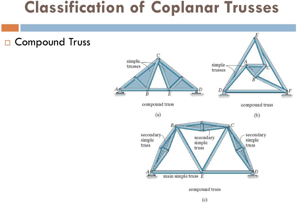
11 Classification of Coplanar Trusses Compound Truss It is formed by connecting 2 or more simple truss together Often, this type of truss is used to support loads acting over a larger span as it is cheaper to construct a lighter compound truss than a heavier simple truss

12 Classification of Coplanar Trusses Compound Truss Type 1 The trusses may be connected by a common joint & bar Type 2 The trusses may be joined by 3 bars Type 3 The trusses may be joined where bars of a large simple truss, called the main truss, have been substituted by simple truss, called secondary trusses

13 Classification of Coplanar Trusses Compound Truss
14 Classification of Coplanar Trusses Complex Truss A complex truss is one that cannot be classified as being either simple or compound

15 Classification of Coplanar Trusses Determinacy The total number of unknowns includes the forces in b number of bars of the truss and the total number of external support reactions r. Since the truss members are all straight axial force members lying in the same plane, the force system acting at each joint is coplanar and concurrent. Consequently, rotational or moment equilibrium is automatically satisfied at the joint (or pin).

16 Classification of Coplanar Trusses Determinacy Therefore only F x and F 0 0 y By comparing the total unknowns with the total number of available equilibrium equations, we have: b r 2 j statically determinate b r 2 j statically indeterminate

17 Classification of Coplanar Trusses Stability If b + r < 2j => collapse A truss can be unstable if it is statically determinate or statically indeterminate Stability will have to be determined either through inspection or by force analysis

18 Classification of Coplanar Trusses Stability External Stability A structure is externally unstable if all of its reactions are concurrent or parallel The trusses are externally unstable since the support reactions have lines of action that are either concurrent or parallel

19 Classification of Coplanar Trusses Internal Stability The internal stability can be checked by careful inspection of the arrangement of its members If it can be determined that each joint is held fixed so that it cannot move in a rigid body sense with respect to the other joints, then the truss will be stable A simple truss will always be internally stable If a truss is constructed so that it does not hold its joints in a fixed position, it will be unstable or have a critical form

20 Classification of Coplanar Trusses Internal Stability To determine the internal stability of a compound truss, it is necessary to identify the way in which the simple truss are connected together The truss shown is unstable since the inner simple truss ABC is connected to DEF using 3 bars which are concurrent at point O

21 Classification of Coplanar Trusses Internal Stability Thus an external load can be applied at A, B or C & cause the truss to rotate slightly For complex truss, it may not be possible to tell by inspection if it is stable The instability of any form of truss may also be noticed by using a computer to solve the 2j simultaneous equations for the joints of the truss If inconsistent results are obtained, the truss is unstable or have a critical form
22 Example 3.1 Classify each of the trusses as stable, unstable, statically determinate or statically indeterminate. The trusses are subjected to arbitrary external loadings that are assumed to be known & can act anywhere on the trusses.
23 Solution For (a), Externally stable Reactions are not concurrent or parallel b = 19, r = 3, j = 11 b + r =2j = 22 Truss is statically determinate By inspection, the truss is internally stable
24 Solution For (b), Externally stable b = 15, r = 4, j = 9 b + r = 19 >2j Truss is statically indeterminate By inspection, the truss is internally stable
25 Solution For (c), Externally stable b = 9, r = 3, j = 6 b + r = 12 = 2j Truss is statically determinate By inspection, the truss is internally stable
26 Solution For (d), Externally stable b = 12, r = 3, j = 8 b + r = 15 < 2j The truss is internally unstable
27 Determination of the member forces The Method of Joints The Method of Sections (Ritter Method) The Graphical Method (Cremona Method)
28 The Method of Joints Satisfying the equilibrium equations for the forces exerted on the pin at each joint of the truss Applications of equations yields 2 algebraic equations that can be solved for the 2 unknowns
29 The Method of Joints Always assume the unknown member forces acting on the joint s free body diagram to be in tension Numerical solution of the equilibrium eqns will yield positive scalars for members in tension & negative for those in compression The correct sense of direction of an unknown member force can in many cases be determined by inspection
30 The Method of Joints A positive answer indicates that the sense is correct, whereas a negative answer indicates that the sense shown on the free-body diagram must be reversed
31 Example 3.2 Determine the force in each member of the roof truss as shown. State whether the members are in tension or compression. The reactions at the supports are given as shown.
32 Solution Only the forces in half the members have to be determined as the truss is symmetric with respect to both loading & geometry, Joint A, F 0; F F F AG AB x y 8kN( C) 0; F 4 F AB 6.93kN( T ) AG sin 30 8cos
33 Solution Joint G, F 0; F F F GB GF 2.60kN( C) x y 0; F GB 8 3sin kN( C) 3cos 30 0 F 0 GF 0 0
34 Solution Joint B, F y 0; F BF sin sin F BF 2.60kN( T ) F F BC x 0; F BC 4.33kN( T ) 2.60cos cos
35 Zero-Force Members Truss analysis using method of joints is greatly simplified if one is able to first determine those members that support no loading These zero-force members may be necessary for the stability of the truss during construction & to provide support if the applied loading is changed The zero-force members of a truss can generally be determined by inspection of the joints & they occur in 2 cases.
36 Zero-Force Members Case 1 The 2 members at joint C are connected together at a right angle & there is no external load on the joint The free-body diagram of joint C indicates that the force in each member must be zero in order to maintain equilibrium
37 Zero-Force Members Case 2 Zero-force members also occur at joints having a geometry as joint D
38 Zero-Force Members Case 2 No external load acts on the joint, so a force summation in the y-direction which is perpendicular to the 2 collinear members requires that F DF = 0 Using this result, FC is also a zero-force member, as indicated by the force analysis of joint F
39 Example 3.4 Using the method of joints, indicate all the members of the truss that have zero force.
40 Solution We have, Joint D, F y 0; F DC sin 0 F 0 F F DC DE x 0 0; F DE 0 0
41 Solution Joint E, F x 0; F EF 0 Joint H, F y 0; F HB 0 Joint G, F y 0; F GA 0
42 The Method of Sections (Ritter Method) If the forces in only a few members of a truss are to be found, the method of sections generally provide the most direct means of obtaining these forces The method is created the German scientist August Ritter ( ). This method consists of passing an imaginary section through the truss, thus cutting it into 2 parts Provided the entire truss is in equilibrium, each of the 2 parts must also be in equilibrium
43 The Method of Sections (Ritter Method) The 3 eqns of equilibrium may be applied to either one of these 2 parts to determine the member forces at the cut section A decision must be made as to how to cut the truss In general, the section should pass through not more than 3 members in which the forces are unknown
44 The Method of Sections (Ritter Method) If the force in GC is to be determined, section a-a will be appropriate Also, the member forces acting on one part of the truss are equal but opposite The 3 unknown member forces, F BC, F GC & F GF can be obtained by applying the 3 equilibrium equations
45 The Method of Sections When applying the equilibrium equations, consider ways of writing the equations to yield a direct solution for each of the unknown, rather than to solve simultaneous equations
46 Example 3.5 Determine the force in members CF and GC of the roof truss. State whether the members are in tension or compression. The reactions at the supports have been calculated.
47 Solution The free-body diagram of member CF can be obtained by considering the section a-a, A direct solution for F Applying Principal of F is slide to point C for simplicity. With anti - clockwise moments as F CF F CF CF sin 30 o 1.73kN( C) CF (4) 1.50(2.31) can be obtained by applying M transmissibility, 0 ve, M E 0 E 0
48 Solution The free-body diagram of member GC can be obtained by considering the section b-b, Moments will be summed about point A in order to eliminate the unknowns F is slide to point C for simplicity. With anti - clockwise moments as ve, M 1.50(2.31) F F CF GC F HG 1.73kN( T ) and GC F CD.Sliding to (4) 1.73sin 30 o F CF (4) 0 point C, we have : A 0
49 Example 3.6 Determine the force in member GF and GD of the truss. State whether the members are in tension or compression. The reactions at the supports have been calculated.
50 Solution The distance EO can be determined by proportional triangles or realizing that member GF drops vertically = 1.5m in 3m. Hence, to drop 4.5m from G the distance from C to O must be 9m
51 Solution The angles F GD and F GF make with the horizontal are tan -1 (4.5/3) = 56.3 o tan -1 (4.5/9) = 26.6 o The force in GF can be determined directly by applying M F 0 is slide to point O. With anti - clockwise moments as ve, M F GF F GF D GF sin 26.6 o 7.83kN( C) (6) 7(3) 0 D 0
52 Solution The force in GD can be determined directly by applying M F 0 is slide to point D. With anti - clockwise moments as ve, M 7(3) 2(6) F F GD GD O GD 1.80kN( C) sin 56.3 o (6) 0 O 0
53 The Graphical Method (Cremona Method) This method deals mainly with the graphical representation of equilibrium for each joint. The basic advantage that makes the method attractive, is its ability to unify all the force polygons, resulting from graphical equilibrium of each joint, into one only force polygon, known as Cremona s diagram. The method was created by the Italian mathematician Luigi Cremona.
54 The Graphical Method (Cremona Method) Although graphical, this method leads to a quick determination of the member forces and is useful specifically in the cases where the external loads and/or the truss members form random angles. Consider the case of graphical analyzing the equilibrium of a point, acted upon 3 forces, one of which is completely known while the other 2 are known in direction only (for example, a lamp hanged by two wires). The procedure: Draw the vector of the completely known force, in the proper direction, scale, magnitude and sense. From one end of the vector, draw a line parallel to the direction of one of the 2 forces, while from the other end draw a second line parallel to the other direction.
55 The Graphical Method (Cremona Method) The vector and the point of section of the two lines define a triangle. Now, following the path of the vector by laying out the 2 unknown forces tip to tail, thus closing the force triangle, we find both the magnitudes and the senses of the other 2 forces. Of course the completely known force can be considered as the resultant of other known forces, through a force polygon. From this procedure we realize that the basic characteristic which appears to be common in the method of joints and Cremona s diagram lies in the main strategic.
56 The Graphical Method (Cremona Method) For analyzing the equilibrium of a joint, in the first method available were 2 equations only, whereas in the second, the two ends of the known-force-vector only. Keeping in mind this similarity for the new method, we can also start and continue with the equilibrium of a joint, where at least one known load exists, while not more than two unknown forces are present. Compared to the analytical method of joints, the graphical method of Cremona s diagram is less precise. However, the loss of precision is unimportant and theoretical. Nevertheless, the speed and the elegance of the method are the main characteristics that make it popular and attractive by many designers.
57 Example 3.7 Determine graphically the force in each of the eleven members of the following truss by the method of Cremona s diagram.
58 Solution We first calculate the support reactions: X = 0 H A = 0 M B = 0 V A = ( 4 kn 4 m + 4 kn 2 m + 2 kn 6 m ) / 4 m = 9 kn V A = 9 kn Y = 0 V B = 2 kn + 4 kn + 4 kn + 2 kn 9 kn = 3 kn V B = 3 kn
59 Solution After drawing the the free body diagram we follow the next steps: 1) Covering the whole area of the free body diagram, we name, say with numbers in circles 1, 2, 3 both the triangles formed by the members and by the external loads so that each member or load separates two areas.
60 Solution 2) Using an appropriate scale (for example 1kN = 1cm) we next draw the force polygon of the external loadings. Each region is represented by a point at the force polygon. The intersection of the parallel lines drawn from one region (point) to the adjacent region gives the point corresponding to the adjacent region. 3) Next, we define a clockwise sequence of forces around a joint. This means that if we start drawing the force triangle for equilibrium of joint B, from, say, the calculated reaction force of 3 kn, the next force considered will be that of member S 11 and not of S 8.
61 Solution
62 The Graphical Method (Cremona Method) A set square with integrated protractor
63 DEFLECTIONS THEORY OF STRUCTURES Asst. Prof. Dr. Cenk Üstündağ
64 Deflection diagrams & the elastic curve Deflections of structures can come from loads, temperature, fabrication errors or settlement In designs, deflections must be limited in order to prevent cracking of attached brittle materials A structure must not vibrate or deflect severely for the comfort of occupants Deflections at specified points must be determined if one is to analyze statically indeterminate structures
65 Deflection diagrams & the elastic curve In this topic, only linear elastic material response is considered This means a structure subjected to load will return to its original undeformed position after the load is removed It is useful to sketch the shape of the structure when it is loaded in order to visualize the computed results & to partially check the results
66 Deflection diagrams & the elastic curve This deflection diagram rep the elastic curve for the points at the centroids of the cross-sectional areas along each of the members If the elastic curve seems difficult to establish, it is suggested that the moment diagram be drawn first From there, the curve can be constructed
67 Deflection diagrams & the elastic curve Due to pin-and-roller support, the disp at A & D must be zero Within the region of ve moment, the elastic curve is concave downward Within the region of +ve moment, the elastic curve is concave upward There must be an inflection point where the curve changes from concave down to concave up
68 Example 8.1 Draw the deflected shape of each of the beams.
69 Solution In (a), the roller at A allows free rotation with no deflection while the fixed wall at B prevents both rotation & deflection. The deflected shape is shown by the bold line. In (b), no rotation or deflection occur at A & B In (c), the couple moment will rotate end A. This will cause deflections at both ends of the beam since no deflection is possible at B & C. Notice that segment CD remains un-deformed since no internal load acts within.
70 Solution In (d), the pin at B allows rotation, so the slope of the deflection curve will suddenly change at this point while the beam is constrained by its support. In (e), the compound beam deflects as shown. The slope changes abruptly on each side of B. In (f), span BC will deflect concave upwards due to load. Since the beam is continuous, the end spans will deflect concave downwards.
71 Elastic Beam Theory To derive the DE, we look at an initially straight beam that is elastically deformed by loads applied perpendicular to beam s x-axis & lying in x-v plane of symmetry Due to loading, the beam deforms under shear & bending If beam L >> d, greatest deformation will be caused by bending When M deforms, the angle between the cross sections becomes d
72 Elastic Beam Theory The arc dx that rep a portion of the elastic curve intersects the neutral axis The radius of curvature for this arc is defined as the distance,, which is measured from ctr of curvature O to dx Any arc on the element other than dx is subjected to normal strain The strain in arc ds located at position y from the neutral axis is ( ds ' ds) / ds
73 Elastic Beam Theory ds dx d and ds' ( y) d ( y) d d d If the material is homogeneous & behaves in a linear manner, then Hooke s law applies / E The flexure formula also applies 1 y My / I
74 Elastic Beam Theory Combining these eqns, we have: 1 M EI the radius of curvature at a specific point on the elastic curve M internal moment in the beam at the point where is to be determined E the material' s modulus of elasticity I the beam' s moment of inertia computed about the neutral axis
75 Elastic Beam Theory 2 3/ / ] ) / ( [1 / Therefore, ] ) / ( [1 / 1, ve axis as v rigidity; flexural dx dv dx v d EI M dx dv dx v d dx EI M dθ ρdθ dx EI
76 Elastic Beam theory This eqn rep a non-linear second DE V=f(x) gives the exact shape of the elastic curve The slope of the elastic curve for most structures is very small Using small deflection theory, we assume dv/dx ~ 0 2 d v 2 dx M EI
77 Elastic Beam Theory By assuming dv/dv ~ 0 ds, it will approximately equal to dx ds 2dx 2 dv 2 21 ( dv / dx) 2 dx dx This implies that points on the elastic curve will only be displaced vertically & not horizontally
78 The double integration method M = f(x), successive integration of eqn 8.4 will yield the beam s slope tan = dv/dx = M/EI dx Eqn of elastic curve V = f(x) = M/EI dx The internal moment in regions AB, BC & CD must be written in terms of x 1, x 2 and x 3
79 The double integration method Once these functions are integrated & the constants determined, the functions will give the slope & deflection for each region of the beam It is important to use the proper sign for M as established by the sign convention used in derivation +ve v is upward, hence, the +ve slope angle, will be measured counterclockwise from the x-axis
80 The double integration method The constants of integration are determined by evaluating the functions for slope or displacement at a particular point on the beam where the value of the function is known These values are called boundary conditions Here x 1 and x 2 coordinates are valid within the regions AB & BC
81 The double integration method Once the functions for the slope & deflections are obtained, they must give the same values for slope & deflection at point B This is so as for the beam to be physically continuous
82 Example 8.1 The cantilevered beam is subjected to a couple moment M o at its end. Determine the eqn of the elastic curve. EI is constant.
83 Solution By inspection, the internal moment can be represented throughout the beam using a single x coordinate. From the free-body diagram, with M acting in +ve direction, we have: M M o Integrating twice yields: EI 2 d v 2 dx M o EI dv dx M o x C 1 EI v M ox 2 2 C x 1 C 2
84 Solution Using boundary conditions, dv/dx = 0 at x = 0 & v = 0 at x = 0 then C 1 = C 2 =0. Substituting these values into earlier eqns, we get: with dv / dx M ox ; v EI M ox 2EI Max slope & disp occur at A (x = L) for which A M ol ; EI v A The +ve result for A indicates counterclockwise rotation & the +ve result for v A indicates that it is upwards. 2 M ol 2EI 2
85 Moment-Area Theorems If we draw the moment diagram for the beam & then divide it by the flexural rigidity, EI, the M/EI diagram is the results d M EI dx
86 Moment-Area Theorems d on either side of the element dx = the lighter shade area under the M/EI diagram Integrating from point A on the elastic curve to point B, we have B M B / A A EI dx This eqn forms the basis for the first moment-area theorem
87 Moment-Area Theorems Theorem 1 The change in slope between any 2 points on the elastic curve equals the area of the M/EI diagram between the 2 points The second moment-area theorem is based on the relative derivation of tangents to the elastic curve Shown in Fig 8.12(c) is a greatly exaggerated view of the vertical deviation dt of the tangents on each side of the differential element, dx
88 Moment-Area theorems Since slope of elastic curve & its deflection are assumed to be very small, it is satisfactory to approximate the length of each tangent line by x & the arc ds by dt Using s = r dt = xd Using eqn 8.2, d = (M/EI) dx The vertical deviation of the tangent at A with respect to the tangent at B can be found by integration t B A / B A x M EI dx
89 Moment-Area Theorems Centroid of an area x da xda t A/ B x B A M EI dx x distance from the vertical axis through A to the centroid of the area between A & B.
90 Moment-Area Theorems Theorem 1 The vertical deviation of the tangent at a point (A) on the elastic curve with respect to the tangent extended from another point (B) equals the moment of the area under the M/EI diagram between the 2 points (A & B) This moment is computed about point A where the derivation is to be determined
91 Moment-Area Theorems Provided the moment of a +ve M/EI area from A to B is computed, it indicates that the tangent at point A is above the tangent to the curve extended from point B -ve areas indicate that the tangent at A is below the tangent extended from B
92 Moment-Area Theorems It is important to realise that the moment-area theorems can only be used to determine the angles & deviations between 2 tangents on the beam s elastic curve In general, they do not give a direct solution for the slope or disp. at a point
93 Example 8.5 Determine the slope at points B & C of the beam. Take E = 200GPa, I = 360(10 6 )mm 4
94 Solution It is easier to solve the problem in terms of EI & substitute the numerical data as a last step. The 10kN load causes the beam to deflect. Here the tangent at A is always horizontal. The tangents at B & C are also indicated. By construction, the angle between tan A and tan B ( B/A ) is equivalent to B.
95 Solution ; B B / A C C / A Applying Theorem 1, is equal to the area under the M/EI diagram between points A & B. B 50kNm B / A EI 2 375kNm EI (5m) 1 100kNm 2 EI 50kNm EI (5m)
96 Solution Substituting numerical data for E & I [200(10 6 ) kn / 375kNm m 2 2 ][360(10 6 )(10 12 ) m 4 ] rad The ve sign indicates that the angle is measured clockwise from A. In a similar manner, the area under the M/EI diagram between points A & C equals ( C/A ).
97 Solution C C / A kNm EI (10m) 500kNm EI 2 Substituting numerical values of EI, we have : [200(10 6 ) kn / 500kNm m 2 2 ][360(10 6 )(10 12 ) m 4 ] rad
98 Conjugate-Beam Method The basis for the method comes from similarity equations To show this similarity, we can write these eqn as shown dv dx d dx w M EI d dx d 2 2 dx M 2 v 2 w M EI
99 Conjugate-Beam Method Or integrating, V wdx M wdxdx M dx EI v M EI dxdx
100 Conjugate-Beam Method Here the shear V compares with the slope θ, the moment M compares with the disp v & the external load w compares with the M/EI diagram To make use of this comparison we will now consider a beam having the same length as the real beam but referred to as the conjugate beam,
101 Conjugate-Beam Method The conjugate beam is loaded with the M/EI diagram derived from the load w on the real beam From the above comparisons, we can state 2 theorems related to the conjugate beam Theorem 1 The slope at a point in the real beam is numerically equal to the shear at the corresponding point in the conjugate beam
102 Conjugate-Beam Method Theorem 2 The disp. of a point in the real beam is numerically equal to the moment at the corresponding point in the conjugate beam When drawing the conjugate beam, it is important that the shear & moment developed at the supports of the conjugate beam account for the corresponding slope & disp of the real beam at its supports
103 Conjugate-Beam Method Consequently from Theorem 1 & 2, the conjugate beam must be supported by a pin or roller since this support has zero moment but has a shear or end reaction When the real beam is fixed supported, both beam has a free end since at this end there is zero shear & moment
104 Conjugate-Beam Method
105 Example 8.5 Determine the max deflection of the steel beam. The reactions have been computed. Take E = 200GPa, I = 60(10 6 )mm 4
106 Solution The conjugate beam loaded with the M/EI diagram is shown. Since M/EI diagram is +ve, the distributed load acts upward. The external reactions on the conjugate beam are determined first and are indicated on the free-body diagram. Max deflection of the real beam occurs at the point where the slope of the beam is zero. Assuming this point acts within the region 0x9m from A we can isolate the section.
107 Solution Note that the peak of the distributed loading was determined from proportional triangles, w / x V ' 0 (18 / EI) / 9 Fy x x 0 EI 2 EI x 6.71m (0 x 9m) OK
108 Solution Using this value for x, the max deflection in the real beam corresponds to the moment M. Hence, With anticlockwise moments as ve, M 0 45 EI (6.71) 1 2 2(6.71) EI (6.71) M ' 0
109 Solution The ve sign indicates the deflection is downward. max M ' [200(10 6 ) kn / 201.2kNm m 2 EI kNm ][60(10 6 ) mm 3 4 (1m 4 /(10 3 ) 4 mm 4 )] m 16.8mm
110 DEFLECTIONS USING ENERGY METHODS THEORY OF STRUCTURES Asst. Prof. Dr. Cenk Üstündağ
111 External Work & Strain Energy For more complicated loadings or for structures such as trusses & frames, it is suggested that energy methods be used for the computations Most energy methods are based on the conservation of energy principal Work done by all external forces acting on a structure, U e is transformed into internal work or strain energy U i U e = U i
112 External Work & Strain Energy If the material s elastic limit is not exceeded, the elastic strain energy will return the structure to its undeformed state when the loads are removed When a force F undergoes a disp dx in the same direction as the force, the work done is d U e = F dx If the total disp is x, the work becomes: U x e Fdx 0
113 External Work & Strain Energy Consider the effect caused by an axial force applied to the end of a bar F is gradually increased from 0 to some limiting value F = P The final elongation of the bar becomes If the material has a linear elastic response, then F = (P/ )x
114 External Work & Strain Energy By integrating we have: U e 1 P 2 Suppose P is already applied to the bar & that another force F is now applied, so that the bar deflects further by an amount
115 External Work & Strain Energy The work done by P when the bar undergoes the further deflection is then d U e = P Here the work represents the shaded rectangular area In this case, P does not change its magnitude since is caused only by F Work = force x disp
116 External Work & Strain Energy When a force P is applied to the bar, followed by an application of the force F, the total work done by both forces is rep by the triangular area ACE The triangular area ABG rep the work of P that is caused by disp The triangular area BCD rep the work of F since this force causes a dsip Lastly the shaded rectangular area BDEG rep the additional work done by P
117 External Work & Strain Energy The work of a moment = magnitude of the moment (M) x the angle (d) through which it rotates d U e = M d If the total angle of rotation is rad, the work becomes Ue Md 0
118 External Work & Strain Energy If the moment is applied gradually to a structure having a linear elastic response from 0 to M, then the work done is Ue 1 M 2 However, if the moment is already applied to the structure & other loadings further distort the structure an amount, then M rotates & the work done is Ue' M '
119 External Work & Strain Energy When an axial force N is applied gradually to the bar, it will strain the material such that the external work done by N will be converted into strain energy Provided the material is linearly elastic, Hooke s Law is valid = E If the bar has a constant x-sectional area A and length L
120 External Work & Strain Energy The normal stress is = N/A The final strain is = /L Consequently, N/A = E(/L) Final deflection: Substituting with P = N, NL AE 2 N L U i 2AE
121 External Work & Strain Energy Consider the beam, P & w are gradually apply These loads create an internal moment M in the beam at a section located a distance x from the left support Consequently, the strain energy or work stored in the element can be determined since the internal moment is gradually developed
122 External Work & Strain Energy Hence, 2 M dx du i 2EI The strain energy for the beam is determined by integrating this result over the beam s length U i L 0 2 M dx 2EI
123 Principle of Work & Energy Consider finding the disp at a point where the force P is applied to the cantilever beam The external work: 1 U e P 2 To obtain the resulting strain energy, we must first determine the internal moment as a function of position x in the beam
124 Principle of Work & Energy In this case, M = - Px so that: U i 0 L 2 M dx 2EI 0 L ( Px) 2EI Equating the ext work to int strain energy & solving for the unknown disp, we have: U 1 2 e U P PL i 3 3EI 1 6 P 2 2 L EI dx P L EI 3
125 Principle of Work & Energy Limitations It will be noted that only one load may be applied to the structure Only the disp under the force can be obtained
126 Principle of Work & Energy If we take a deformable structure of any shape or size & apply a series of external loads P to it, it will cause internal loads u at points throughout the structure As a consequence of these loadings, external disp will occur at the P loads & internal disp will occur at each point of internal loads u In general, these disp do not have to be elastic, & they may not be related to the loads
127 Principle of Virtual Work In general, the principle states that: P u Work of Ext loads Work of Int loads Consider the structure (or body) to be of arbitrary shape Suppose it is necessary to determine the disp of point A on the body caused by the real loads P 1, P 2 and P 3
128 Principle of Virtual Work It is to be understood that these loads cause no movement of the supports They can strain the material beyond the elastic limit Since no external load acts on the body at A and in the direction of, the disp, the disp can be determined by first placing on the body a virtual load such that this force P acts in the same direction as
129 Principle of Virtual Work We will choose P to have a unit magnitude, P =1 Once the virtual loadings are applied, then the body is subjected to the real loads P 1, P 2 and P 3, Point A will be displaced an amount causing the element to deform an amount dl
130 Principle of Virtual Work As a result, the external virtual force P & internal load u ride along by and dl & therefore, perform external virtual work of 1. on the body and internal virtual work of u.dl on the element 1. u.dl By choosing P = 1, it can be seen from the solution for follows directly since = udl A virtual couple moment M having a unit magnitude is applied at this point
131 Principle of Virtual Work This couple moment causes a virtual load u in one of the elements of the body Assuming that the real loads deform the element an amount dl, the rotation can be found from the virtual work eqn 1. u.dl
132 Method of virtual work: Beams & Frames To compute a virtual unit load acting in the direction of is placed on the beam at A The internal virtual moment m is determined by the method of sections at an arbitrary location x from the left support When point A is displaced, the element dx deforms or rotates d = (M/EI)dx
133 Method of virtual work: Beams & Frames L 1. 0 mm EI external virtual unit load acting on the beam or frame in the direction of internal virtual moment in the beam or frame, expressed as a function of x & caused by the ext virtual unit load ext disp of the point caused by real loads acting on the beam or frame int moment in the beam or frame, expressed as a function of x & caused by the real loads modulus of elasticity of the material moment of inertia of cross - sectional area, computed about the neutral axis dx
134 Method of virtual work: Beams & Frames If the tangent rotation or slope angle at a point on the beam s elastic curve is to be determined, a unit couple moment is applied at the point The corresponding int moment m have to be determined m M EI L 1. 0 dx
135 Method of virtual work: Beams & Frames If concentrated forces or couple moments act on the beam or the distributed load is discontinuous, separate x coordinates will have to chosen within regions that have no discontinuity of loading
136 Example 9.4 Determine the disp of point B of the steel beam. Take E = 200GPa and I = 500(10 6 ) mm 4.
137 Solution Virtual moment m The vertical disp of point B is obtained by placing a virtual unit load of 1kN at B. Using method of sections, the internal moment m is formulated. Real moment M Using the same x coordinate, M is formulated.
138 Virtual work eqn Solution mm m EI m kn kn dx EI x x dx EI mm kn B B L B ) 15(10. 1 ) 6 )( 1 (
139 Method of virtual work: M i M k Table
140 Analysis of Statically Indeterminate Structures by the Force Method THEORY OF STRUCTURES Asst. Prof. Dr. Cenk Üstündağ
141 Statically Indeterminate Structures Advantages & Disadvantages For a given loading, the max stress and deflection of an indeterminate structure are generally smaller than those of its statically determinate counterpart Statically indeterminate structure has a tendency to redistribute its load to its redundant supports in cases of faulty designs or overloading
142 Statically Indeterminate Structures Advantages & Disadvantages Although statically indeterminate structure can support loading with thinner members & with increased stability compared to their statically determinate counterpart, the cost savings in material must be compared with the added cost to fabricate the structure since often it becomes more costly to construct the supports & joints of an indeterminate structure Because statically indeterminate structures have redundant support reactions, one has to be very careful to prevent differential displacement of the supports, since this effect will introduce internal stress in the structure.
143 Statically Indeterminate Structures Method of Analysis When analyzing any indeterminate structure, it is necessary to satisfy equilibrium, compatibility, and force-displacement requirements for the structure. Equilibrium is satisfied when the reactive forces hold the structure at rest, and compatibility is satisfied when the various segments of the structure fit together without intentional breaks or overlaps. The force-displacement requirements depend upon the way the material responds; (Here we assume linear elastic response).
144 Statically Indeterminate Structures Force Method The force method was originally developed by James Clerk Maxwell (a Scottish physicist and mathematician) in 1864 and later refined by Otto Mohr and Heinrich Müller-Breslau (German civil engineers). Displacement Method
145 Statically Indeterminate Structures Force Method: The force method consists of writing equations that satisfy the compatibility and force-displacement requirements for the structure in order to determine the redundant forces. Once these forces have been determined, the remaining reactive forces on the structure are determined by satisfying the equilibrium requirements. Displacement Method: The displacement method of analysis is based on first writing force-displacement relations for the members and then satisfying the equilibrium requirements for the structure. In this case the unknowns in the equations are displacements. Once the displacements are obtained, the forces are determined from the compatibility and force-displacement equations.
146 Statically Indeterminate Structures Unknowns Equations Used for Solution Coefficents of the Unknowns Force Method Forces Compatibility and Force Displacement Flexibility Coefficents Displacement Method Displacements Equilibirum and Force Displacement Stiffness Coefficients
147 Force Method of Analysis: General Procedure From free-body diagram, there would be 4 unknown support reactions 3 equilibrium equations Beam is indeterminate to first degree Use principle of superposition & consider the compatibility of displacement at one of the supports Choose one of the support reactions as redundant & temporarily removing its effect on the beam
148 Force Method of Analysis: General Procedure This will allow the beam to be statically determinate & stable Here,wewillremovetherocker at B As a result, the load P will cause B to be displaced downward By superposition, the unknown reaction at B causes the beam at B to be displaced upward
149 Force Method of Analysis: General Procedure Assuming positive displacements act upward, then we can write the necessary compatibility equation at the rocker as 0 ' B BB Here the first letter in this doublesubscript notation refers to the point (B) where the deflection is specified, and the second letter refers to the point (B) where the unknown reaction acts.
150 Force Method of Analysis: General Procedure Let us denote the displacement at B caused by a unit load acting in the direction of B y as the linear flexibility coefficient f BB. Since the material behaves in a linear-elastic manner, a force of B y acting at B, instead of the unit load, will cause a proportionate increase in f BB. ' BB Bf y BB
151 Force Method of Analysis: General Procedure The linear flexibility coefficient f BB is a measure of the deflection per unit force, and so its units are m/n. The compatibility equation above can therefore be written in terms of the unknown B y as 0 B f B y BB
152 Force Method of Analysis: General Procedure Using the method of virtual work the appropriate loaddisplacement relations for the deflection B and the flexibility coefficient f BB, can be obtained and the solution for B y can be determined. Once this is accomplished, the three reactions at the wall A can then be found from the equations of equilibrium. The choice of redundant is arbitrary
153 Force Method of Analysis: General Procedure The moment at A can be determined directly by removing the capacity of the beam to support moment at A, replacing fixed support by pin support The rotation at A caused by P is A The rotation at A caused by the redundant M A at A is AA
154 Force Method of Analysis: General Procedure If we denote an angular flexibility coefficient AA as the angular displacement at A caused by a unit couple moment applied to A, then ' AA M A AA Thus, the angular flexibility coefficient measures the angular displacement per unit couple moment, and therefore it has units of rad/n. The compatibility equation for rotation at A therefore requires 0 AMA AA
155 Maxwell s Theorem of Reciprocal Displacements: Betti s Law The displacement of a point B on a structure due to a unit load acting at point A is equal to the displacement of point A when the load is acting at point B f BA f AB Proof of this theorem is easily demonstrated using the principle of virtual work
156 Maxwell s Theorem of Reciprocal Displacements: Betti s Law The theorem also applies for reciprocal rotations The rotation at point B on a structure due to a unit couple moment acting at point A is equal to the rotation at point A when the unit couple is acting at point B
157 Example 10.1 Determine the reaction at the roller support B of the beam. EI is constant.
158 Solution Principle of superposition By inspection, the beam is statically indeterminate to the first degree. The redundant will be taken as B y. We assume B y acts upward on the beam.
159 Solution Compatibility equation ( ) 0 B B y f BB eqn(1) B and f BB are easily obtained using standard table. B 9000kNm EI 3 ; f BB 576m EI 3 Sub into eqn (1) : EI B y 576 EI B y 15.6kN
160 Solution
161 Example 10.4 Draw the shear and moment diagrams for the beam. EI is constant. Neglect the effects of axial load.
162 Solution Principle of Superposition Since axial load is neglected, the beam is indeterminate to the second degree. The 2 end moments at A & B will be considered as the redundant. The beam s capacity to resist these moments is removed by placing a pin at A and a rocker at B.
163 Solution Compatibility eqn Reference to points A & B requires 0 A M A AA M B AB eqn (1) 0 B M A BA M B BB eqn (2) The required slopes and angular flexibility coefficients can be determined using standard tables. A ; EI A EI AA 2 EI ; BB 2 EI ; AB BA 1 EI
164 Solution Compatibility eqn Sub into eqn (1) and (2)gives : EI M A 2 EI M B 1 EI EI M A 1 EI M B 2 EI M A 61.9kNm; M B 28.1kNm,
165 Displacement Method of Analysis: Moment Distribution THEORY OF STRUCTURES Asst. Prof. Dr. Cenk Üstündağ
166 General Principles & Definition Displacement method requires satisfying equilibrium equations for the structures The unknowns displacement are written in terms of the loads by using the load-displacement relations These equations are solved for the displacement Once the displacement are obtained, the unknown loads are determined from the compatibility equations using the load displacement relations
167 General Principles & Definition The method of analyzing beams and frames using moment distribution was developed by Hardy Cross, in At the time this method was first published it attracted immediate attention, and it has been recognized as one of the most notable advances in structural analysis during the twentieth century.
168 General Principles & Definition Moment distribution is a method of successive approximations that may be carried out to any desired degree of accuracy The method begins by assuming each joint of a structure is fixed By unlocking and locking each joint in succession, the internal moments at the joints are distributed & balanced until the joints have rotated to their final or nearly final positions
169 General Principles & Definition Sign Convention We will establish the same sign convention as that established for the slope-deflection equations: Clockwise moments that act on the member are considered positive, whereas counterclockwise moments are negative.
170 General Principles & Definition Fixed-End Moments (FEMs) The moments at the walls or fixed joints of a loaded member are called fixed-end moments. These moments can be determined from the table on the right side depending upon the type of loading on the member.
171 General Principles & Definition For example, the beam loaded as shown in figure has fixed-end moments of FEM = PL/8 = 800(10)/8 = 1000 Nm. Noting the action of these moments on the beam and applying our sign convention, it is seen that M AB = -1000Nm and M BA =1000Nm
172 General Principles & Definition Member stiffness factor Consider the beam in the figure, which is pinned at one end and fixed at the other. Application of the moment M causes the end A to rotate through an angle A. Using the conjugate-beam method M can be related to A as follows: 4 The term in parentheses 4 is referred to as the stiffness factor at A and can be defined as the amount of moment M required to rotate the end A of the beam A =1 rad. M M A' 1 M 2 EI B' 1 M 2 EI 0 AB 0 BA L 1 M L 3 2 EI BA L 1 M L 3 2 EI AB 2L L 3 2L L 3 0 L 0 A
173 General Principles & Definition Joint stiffness factor If several members are fixed connected to joint and each of their far ends is fixed, then by the principle of superposition, the total stiffness factor at the joint is the sum of the member stiffness factors at the joint. The total stiffness factor of joint A is K T K
174 General Principles & Definition Distribution Factor (DF) If a moment M is applied to a fixed connected joint, the connecting members will each supply a portion of the resisting moment necessary to satisfy moment equilibrium at the joint. That fraction of the total resisting moment supplied by the member is called the distribution factor (DF). DF i DF M M i K K Ki K i
175 General Principles & Definition Member relative stiffness factor Quite often a continuous beam or a frame will be made from the same material E will therefore be constant In the case, the common factor 4E will cancel from the numerator and denominator when the distribution factor for a joint is determined. K R I L
176 General Principles & Definition Carry-over (CO) factor 4EI 2EI M AB A ; M BA L L Solving for and equating these equations, M 0. 5 BA M AB The moment M at the pin induces a moment of M = 0.5M at the wall In the case of a beam with the far end fixed, the CO factor is +0.5 A
177 General Principles & Definition Carry-over (CO) factor The plus sign indicates both moments act in the same direction Consider the beam K K BA BC DF DF 6 4E(120)(10 ) 6 4 4E(40)(10 ) mm 3 6 4E(240)(10 ) 6 4E(60)(10 ) mm 4 4E(40) 0.4 4E(40) 4E(60) BA BC 4E(60) 4E(40) 4E(60) / m / m
178 General Principles & Definition DF AB 4E(40) 4E(40) 0 DF CB 4E(60) 4E(60) 0 Note that the above results could also have been obtained if the relative stiffness factor is used ( FEM ) ( FEM ) BC CB 2 wl 8000kNm 12 2 wl 8000kNm 12
179 General Principles & Definition We begin by assuming joint B is fixed or locked The fixed end moment at B then holds span BC in this fixed or locked position To correct this, we will apply an equal but opposite moment of 8000Nm to the joint and allow the joint to rotate freely
180 General Principles & Definition As a result, portions of this moment are distributed in spans BC and BA in accordance with the DFs of these spans at the joint Moment in BA is 0.4(8000) = 3200Nm Moment in BC is 0.6(8000) = 4800Nm These moment must be carried over since moments are developed at the far ends of the span
181 General Principles & Definition Using the carry-over factor of +0.5, the results are shown The steps are usually presented in tabular form CO indicates a line where moments are distributed then carried over In this particular case only one cycle of moment distribution is necessary The wall supports at A and C absorb the moments and no further joints have to be balanced to satisfy joint equilibrium
182 General Principles & Definition
183 Example Determine the internal moment at each support of the beam. The moment of inertia of each span is indicated.
184 Solution A moment does not get distributed in the overhanging span AB So the distribution factor (DF) BA =0 Span BC is based on 4EI/L since the pin rocker is not at the far end of the beam 6 4E(300)(10 ) 6 K BC 300(10 ) E 4 K CD 4E(240)( ) 320(10 6 ) E
185 Solution Nm wl FEM Nm wl FEM Nm m N FEM DF DF E E E DF DF DF CB BC BA DC CD CB BA BC ) ( ) ( 4000 ) ( ) ( Due to overhang, ; ) ( 1 2 2
186 Solution The overhanging span requires the internal moment to the left of B to be +4000Nm. Balancing at joint B requires an internal moment of 4000Nm to the right of B Nm is added to BC in order to satisfy this condition. The distribution & CO operations proceed in the usual manner. Since the internal moments are known, the moment diagram for the beam can be constructed.
187 Solution
188 Stiffness-Factor Modifications The previous e.g. of moment distribution, we have considered each beam span to be constrained by a fixed support at its far end when distributing & carrying over the moments. For this reason we have computed the stiffness factors, distribution factors, and the carry-over factors based on the case shown in figure below. In some cases, it is possible to modify the stiffness factor of a particular beam span & thereby simplify the process of moment distribution
189 Stiffness-Factor Modifications L EI M EI L V L L EI M L V M A A B 3 3 ' ) ( ' 0 ' Member pin supported at far end As shown the applied moment M rotates end A by an amount To determine, the shear in the conjugate beam at A must be determined
190 Stiffness-Factor Modifications Member pin supported at far end (cont d) The stiffness factor in the beam is K 3EI L The CO factor is zero, since the pin at B does not support a moment By comparison, if the far end was fixed supported, the stiffness factor would have to be modified by ¾ to model the case of having the far end pin supported. If this modification is considered, the moment distribution process is simplified since the end pin does not have to be unlocked locked successively when distributing the moments
191 Stiffness-Factor Modifications Symmetric beam & loading The bending-moment diagram for the beam will also be symmetric To develop the appropriate stiffness-factor modification consider the beam Due to symmetry, the internal moment at B & C are equal Assuming this value to be M, the conjugate beam for span BC is shown
192 Stiffness-Factor Modifications L EI K L EI M EI ML V L L EI M L V M B B C ' 0 2 ) ( ' - 0 ' Symmetric beam & loading (cont d) Moments for only half the beam can be distributed provided the stiffness factor for the center span is computed
193 Stiffness-Factor Modifications Symmetric beam with asymmetric loading Consider the beam as shown The conjugate beam for its center span BC is shown Due to its asymmetric loading, the internal moment at B is equal but opposite to that at C
194 Stiffness-Factor Modifications L EI K L EI M EI ML V L L EI M L L EI M L V M B B C ' ) ( ' - 0 ' Symmetric beam with asymmetric loading Assuming this value to be M, the slope at each end is determined as follows:
195 Example Determine the internal moments at the supports of the beam shown below. The moment of inertia of the two spans is shown in the figure.
196 Solution The beam is roller supported at its far end C. The stiffness of span BC will be computed on the basis of K = 3EI/L We have: K AB 4EI L 4E(120)( ) 160(10 6 ) E K BC 3EI L 3E(240)( ) 180(10 6 ) E
197 Solution E E DF E E E DF E E E DF E E DF CB BC BA AB Nm wl FEM BC (4) 8 ) ( 2 2
198 Solution The forgoing data are entered into table as shown. The moment distribution is carried out. By comparison, the method considerably simplifies the distribution.
Structural Axial, Shear and Bending Moments
 Structural Axial, Shear and Bending Moments Positive Internal Forces Acting Recall from mechanics of materials that the internal forces P (generic axial), V (shear) and M (moment) represent resultants
Deflections. Question: What are Structural Deflections?
 Question: What are Structural Deflections? Answer: The deformations or movements of a structure and its components, such as beams and trusses, from their original positions. It is as important for the
PLANE TRUSSES. Definitions
 Definitions PLANE TRUSSES A truss is one of the major types of engineering structures which provides a practical and economical solution for many engineering constructions, especially in the design of
Statics of Structural Supports
 Statics of Structural Supports TYPES OF FORCES External Forces actions of other bodies on the structure under consideration. Internal Forces forces and couples exerted on a member or portion of the structure
8.2 Elastic Strain Energy
 Section 8. 8. Elastic Strain Energy The strain energy stored in an elastic material upon deformation is calculated below for a number of different geometries and loading conditions. These expressions for
Mechanics of Materials. Chapter 4 Shear and Moment In Beams
 Mechanics of Materials Chapter 4 Shear and Moment In Beams 4.1 Introduction The term beam refers to a slender bar that carries transverse loading; that is, the applied force are perpendicular to the bar.
Bending Stress in Beams
 936-73-600 Bending Stress in Beams Derive a relationship for bending stress in a beam: Basic Assumptions:. Deflections are very small with respect to the depth of the beam. Plane sections before bending
Module 2. Analysis of Statically Indeterminate Structures by the Matrix Force Method. Version 2 CE IIT, Kharagpur
 Module Analysis of Statically Indeterminate Structures by the Matrix Force Method esson 11 The Force Method of Analysis: Frames Instructional Objectives After reading this chapter the student will be able
Copyright 2011 Casa Software Ltd. www.casaxps.com. Centre of Mass
 Centre of Mass A central theme in mathematical modelling is that of reducing complex problems to simpler, and hopefully, equivalent problems for which mathematical analysis is possible. The concept of
Stresses in Beam (Basic Topics)
") Chapter 5 Stresses in Beam (Basic Topics) 5.1 Introduction Beam : loads acting transversely to the longitudinal axis the loads create shear forces and bending moments, stresses and strains due to V and
Chapter 5 Stresses in Beam (Basic Topics) 5.1 Introduction Beam : loads acting transversely to the longitudinal axis the loads create shear forces and bending moments, stresses and strains due to V and
Problem 1: Computation of Reactions. Problem 2: Computation of Reactions. Problem 3: Computation of Reactions
 Problem 1: Computation of Reactions Problem 2: Computation of Reactions Problem 3: Computation of Reactions Problem 4: Computation of forces and moments Problem 5: Bending Moment and Shear force Problem
MECHANICS OF SOLIDS - BEAMS TUTORIAL 2 SHEAR FORCE AND BENDING MOMENTS IN BEAMS
 MECHANICS OF SOLIDS - BEAMS TUTORIAL 2 SHEAR FORCE AND BENDING MOMENTS IN BEAMS This is the second tutorial on bending of beams. You should judge your progress by completing the self assessment exercises.
Shear Forces and Bending Moments
 Chapter 4 Shear Forces and Bending Moments 4.1 Introduction Consider a beam subjected to transverse loads as shown in figure, the deflections occur in the plane same as the loading plane, is called the
The elements used in commercial codes can be classified in two basic categories:
 CHAPTER 3 Truss Element 3.1 Introduction The single most important concept in understanding FEA, is the basic understanding of various finite elements that we employ in an analysis. Elements are used for
Approximate Analysis of Statically Indeterminate Structures
 Approximate Analysis of Statically Indeterminate Structures Every successful structure must be capable of reaching stable equilibrium under its applied loads, regardless of structural behavior. Exact analysis
INTRODUCTION TO BEAMS
 CHAPTER Structural Steel Design LRFD Method INTRODUCTION TO BEAMS Third Edition A. J. Clark School of Engineering Department of Civil and Environmental Engineering Part II Structural Steel Design and Analysis
Section 16: Neutral Axis and Parallel Axis Theorem 16-1
 Section 16: Neutral Axis and Parallel Axis Theorem 16-1 Geometry of deformation We will consider the deformation of an ideal, isotropic prismatic beam the cross section is symmetric about y-axis All parts
ENGINEERING MECHANICS STATIC
 EX 16 Using the method of joints, determine the force in each member of the truss shown. State whether each member in tension or in compression. Sol Free-body diagram of the pin at B X = 0 500- BC sin
Statically determinate structures
 Statically determinate structures A statically determinate structure is the one in which reactions and internal forces can be determined solely from free-body diagrams and equations of equilibrium. These
EDEXCEL NATIONAL CERTIFICATE/DIPLOMA MECHANICAL PRINCIPLES AND APPLICATIONS NQF LEVEL 3 OUTCOME 1 - LOADING SYSTEMS
 EDEXCEL NATIONAL CERTIFICATE/DIPLOMA MECHANICAL PRINCIPLES AND APPLICATIONS NQF LEVEL 3 OUTCOME 1 - LOADING SYSTEMS TUTORIAL 1 NON-CONCURRENT COPLANAR FORCE SYSTEMS 1. Be able to determine the effects
2. Axial Force, Shear Force, Torque and Bending Moment Diagrams
 2. Axial Force, Shear Force, Torque and Bending Moment Diagrams In this section, we learn how to summarize the internal actions (shear force and bending moment) that occur throughout an axial member, shaft,
ENGINEERING SCIENCE H1 OUTCOME 1 - TUTORIAL 3 BENDING MOMENTS EDEXCEL HNC/D ENGINEERING SCIENCE LEVEL 4 H1 FORMERLY UNIT 21718P
 ENGINEERING SCIENCE H1 OUTCOME 1 - TUTORIAL 3 BENDING MOMENTS EDEXCEL HNC/D ENGINEERING SCIENCE LEVEL 4 H1 FORMERLY UNIT 21718P This material is duplicated in the Mechanical Principles module H2 and those
Advanced Structural Analysis. Prof. Devdas Menon. Department of Civil Engineering. Indian Institute of Technology, Madras. Module - 5.3.
 Advanced Structural Analysis Prof. Devdas Menon Department of Civil Engineering Indian Institute of Technology, Madras Module - 5.3 Lecture - 29 Matrix Analysis of Beams and Grids Good morning. This is
MECHANICS OF SOLIDS - BEAMS TUTORIAL 1 STRESSES IN BEAMS DUE TO BENDING. On completion of this tutorial you should be able to do the following.
 MECHANICS OF SOLIDS - BEAMS TUTOIAL 1 STESSES IN BEAMS DUE TO BENDING This is the first tutorial on bending of beams designed for anyone wishing to study it at a fairly advanced level. You should judge
DESIGN OF SLABS. 3) Based on support or boundary condition: Simply supported, Cantilever slab,
 Based on support or boundary condition: Simply supported, Cantilever slab,") DESIGN OF SLABS Dr. G. P. Chandradhara Professor of Civil Engineering S. J. College of Engineering Mysore 1. GENERAL A slab is a flat two dimensional planar structural element having thickness small compared
DESIGN OF SLABS Dr. G. P. Chandradhara Professor of Civil Engineering S. J. College of Engineering Mysore 1. GENERAL A slab is a flat two dimensional planar structural element having thickness small compared
P4 Stress and Strain Dr. A.B. Zavatsky MT07 Lecture 3 Statically Indeterminate Structures
 4 Stress and Strain Dr... Zavatsky MT07 ecture 3 Statically Indeterminate Structures Statically determinate structures. Statically indeterminate structures (equations of equilibrium, compatibility, and
Design of Steel Structures Prof. S.R.Satish Kumar and Prof. A.R.Santha Kumar. Fig. 7.21 some of the trusses that are used in steel bridges
 7.7 Truss bridges Fig. 7.21 some of the trusses that are used in steel bridges Truss Girders, lattice girders or open web girders are efficient and economical structural systems, since the members experience
ANALYTICAL METHODS FOR ENGINEERS
 UNIT 1: Unit code: QCF Level: 4 Credit value: 15 ANALYTICAL METHODS FOR ENGINEERS A/601/1401 OUTCOME - TRIGONOMETRIC METHODS TUTORIAL 1 SINUSOIDAL FUNCTION Be able to analyse and model engineering situations
STRESS AND DEFORMATION ANALYSIS OF LINEAR ELASTIC BARS IN TENSION
 Chapter 11 STRESS AND DEFORMATION ANALYSIS OF LINEAR ELASTIC BARS IN TENSION Figure 11.1: In Chapter10, the equilibrium, kinematic and constitutive equations for a general three-dimensional solid deformable
When the fluid velocity is zero, called the hydrostatic condition, the pressure variation is due only to the weight of the fluid.
 Fluid Statics When the fluid velocity is zero, called the hydrostatic condition, the pressure variation is due only to the weight of the fluid. Consider a small wedge of fluid at rest of size Δx, Δz, Δs
Statically Indeterminate Structure. : More unknowns than equations: Statically Indeterminate
 Statically Indeterminate Structure : More unknowns than equations: Statically Indeterminate 1 Plane Truss :: Determinacy No. of unknown reactions = 3 No. of equilibrium equations = 3 : Statically Determinate
SOLID MECHANICS TUTORIAL MECHANISMS KINEMATICS - VELOCITY AND ACCELERATION DIAGRAMS
 SOLID MECHANICS TUTORIAL MECHANISMS KINEMATICS - VELOCITY AND ACCELERATION DIAGRAMS This work covers elements of the syllabus for the Engineering Council exams C105 Mechanical and Structural Engineering
Figure 1.1 Vector A and Vector F
 CHAPTER I VECTOR QUANTITIES Quantities are anything which can be measured, and stated with number. Quantities in physics are divided into two types; scalar and vector quantities. Scalar quantities have
Analysis of Stresses and Strains
 Chapter 7 Analysis of Stresses and Strains 7.1 Introduction axial load = P / A torsional load in circular shaft = T / I p bending moment and shear force in beam = M y / I = V Q / I b in this chapter, we
Solving Simultaneous Equations and Matrices
 Solving Simultaneous Equations and Matrices The following represents a systematic investigation for the steps used to solve two simultaneous linear equations in two unknowns. The motivation for considering
Reflection and Refraction
 Equipment Reflection and Refraction Acrylic block set, plane-concave-convex universal mirror, cork board, cork board stand, pins, flashlight, protractor, ruler, mirror worksheet, rectangular block worksheet,
Introduction to Beam. Area Moments of Inertia, Deflection, and Volumes of Beams
 Introduction to Beam Theory Area Moments of Inertia, Deflection, and Volumes of Beams Horizontal structural member used to support horizontal loads such as floors, roofs, and decks. Types of beam loads
4.2 Free Body Diagrams
 CE297-FA09-Ch4 Page 1 Friday, September 18, 2009 12:11 AM Chapter 4: Equilibrium of Rigid Bodies A (rigid) body is said to in equilibrium if the vector sum of ALL forces and all their moments taken about
Structural Analysis - II Prof. P. Banerjee Department of Civil Engineering Indian Institute of Technology, Bombay. Lecture - 02
 Structural Analysis - II Prof. P. Banerjee Department of Civil Engineering Indian Institute of Technology, Bombay Lecture - 02 Good morning. Today is the second lecture in the series of lectures on structural
New approaches in Eurocode 3 efficient global structural design
 New approaches in Eurocode 3 efficient global structural design Part 1: 3D model based analysis using general beam-column FEM Ferenc Papp* and József Szalai ** * Associate Professor, Department of Structural
6. Vectors. 1 2009-2016 Scott Surgent ([email protected])
") 6. Vectors For purposes of applications in calculus and physics, a vector has both a direction and a magnitude (length), and is usually represented as an arrow. The start of the arrow is the vector s foot,
6. Vectors For purposes of applications in calculus and physics, a vector has both a direction and a magnitude (length), and is usually represented as an arrow. The start of the arrow is the vector s foot,
EDEXCEL NATIONAL CERTIFICATE/DIPLOMA MECHANICAL PRINCIPLES AND APPLICATIONS NQF LEVEL 3 OUTCOME 1 - LOADING SYSTEMS TUTORIAL 3 LOADED COMPONENTS
 EDEXCEL NATIONAL CERTIICATE/DIPLOMA MECHANICAL PRINCIPLES AND APPLICATIONS NQ LEVEL 3 OUTCOME 1 - LOADING SYSTEMS TUTORIAL 3 LOADED COMPONENTS 1. Be able to determine the effects of loading in static engineering
Optimum proportions for the design of suspension bridge
 Journal of Civil Engineering (IEB), 34 (1) (26) 1-14 Optimum proportions for the design of suspension bridge Tanvir Manzur and Alamgir Habib Department of Civil Engineering Bangladesh University of Engineering
Objectives. Experimentally determine the yield strength, tensile strength, and modules of elasticity and ductility of given materials.
 Lab 3 Tension Test Objectives Concepts Background Experimental Procedure Report Requirements Discussion Objectives Experimentally determine the yield strength, tensile strength, and modules of elasticity
Unified Lecture # 4 Vectors
 Fall 2005 Unified Lecture # 4 Vectors These notes were written by J. Peraire as a review of vectors for Dynamics 16.07. They have been adapted for Unified Engineering by R. Radovitzky. References [1] Feynmann,
Chapter 11 Equilibrium
 11.1 The First Condition of Equilibrium The first condition of equilibrium deals with the forces that cause possible translations of a body. The simplest way to define the translational equilibrium of
MODULE E: BEAM-COLUMNS
 MODULE E: BEAM-COLUMNS This module of CIE 428 covers the following subjects P-M interaction formulas Moment amplification Web local buckling Braced and unbraced frames Members in braced frames Members
Lecture L22-2D Rigid Body Dynamics: Work and Energy
 J. Peraire, S. Widnall 6.07 Dynamics Fall 008 Version.0 Lecture L - D Rigid Body Dynamics: Work and Energy In this lecture, we will revisit the principle of work and energy introduced in lecture L-3 for
Rigid and Braced Frames
 Rigid Frames Rigid and raced Frames Rigid frames are identified b the lack of pinned joints within the frame. The joints are rigid and resist rotation. The ma be supported b pins or fied supports. The
Awell-known lecture demonstration1
 Acceleration of a Pulled Spool Carl E. Mungan, Physics Department, U.S. Naval Academy, Annapolis, MD 40-506; [email protected] Awell-known lecture demonstration consists of pulling a spool by the free end
www.mathsbox.org.uk Displacement (x) Velocity (v) Acceleration (a) x = f(t) differentiate v = dx Acceleration Velocity (v) Displacement x
 Velocity (v) Acceleration (a) x = f(t) differentiate v = dx Acceleration Velocity (v) Displacement x") Mechanics 2 : Revision Notes 1. Kinematics and variable acceleration Displacement (x) Velocity (v) Acceleration (a) x = f(t) differentiate v = dx differentiate a = dv = d2 x dt dt dt 2 Acceleration Velocity
Mechanics 2 : Revision Notes 1. Kinematics and variable acceleration Displacement (x) Velocity (v) Acceleration (a) x = f(t) differentiate v = dx differentiate a = dv = d2 x dt dt dt 2 Acceleration Velocity
COMPLEX STRESS TUTORIAL 3 COMPLEX STRESS AND STRAIN
 COMPLX STRSS TUTORIAL COMPLX STRSS AND STRAIN This tutorial is not part of the decel unit mechanical Principles but covers elements of the following sllabi. o Parts of the ngineering Council eam subject
THEORETICAL MECHANICS
 PROF. DR. ING. VASILE SZOLGA THEORETICAL MECHANICS LECTURE NOTES AND SAMPLE PROBLEMS PART ONE STATICS OF THE PARTICLE, OF THE RIGID BODY AND OF THE SYSTEMS OF BODIES KINEMATICS OF THE PARTICLE 2010 0 Contents
Stress Analysis, Strain Analysis, and Shearing of Soils
 C H A P T E R 4 Stress Analysis, Strain Analysis, and Shearing of Soils Ut tensio sic vis (strains and stresses are related linearly). Robert Hooke So I think we really have to, first, make some new kind
MATRIX ALGEBRA AND SYSTEMS OF EQUATIONS
 MATRIX ALGEBRA AND SYSTEMS OF EQUATIONS Systems of Equations and Matrices Representation of a linear system The general system of m equations in n unknowns can be written a x + a 2 x 2 + + a n x n b a
88 CHAPTER 2. VECTOR FUNCTIONS. . First, we need to compute T (s). a By definition, r (s) T (s) = 1 a sin s a. sin s a, cos s a
. a By definition, r (s) T (s) = 1 a sin s a. sin s a, cos s a") 88 CHAPTER. VECTOR FUNCTIONS.4 Curvature.4.1 Definitions and Examples The notion of curvature measures how sharply a curve bends. We would expect the curvature to be 0 for a straight line, to be very small
88 CHAPTER. VECTOR FUNCTIONS.4 Curvature.4.1 Definitions and Examples The notion of curvature measures how sharply a curve bends. We would expect the curvature to be 0 for a straight line, to be very small
Finite Element Simulation of Simple Bending Problem and Code Development in C++
 EUROPEAN ACADEMIC RESEARCH, VOL. I, ISSUE 6/ SEPEMBER 013 ISSN 86-48, www.euacademic.org IMPACT FACTOR: 0.485 (GIF) Finite Element Simulation of Simple Bending Problem and Code Development in C++ ABDUL
Elasticity Theory Basics
 G22.3033-002: Topics in Computer Graphics: Lecture #7 Geometric Modeling New York University Elasticity Theory Basics Lecture #7: 20 October 2003 Lecturer: Denis Zorin Scribe: Adrian Secord, Yotam Gingold
SOLUTION 6 6. Determine the force in each member of the truss, and state if the members are in tension or compression.
 6 6. etermine the force in each member of the truss, and state if the members are in tension or compression. 600 N 4 m Method of Joints: We will begin by analyzing the equilibrium of joint, and then proceed
CLASSICAL STRUCTURAL ANALYSIS
 Table of Contents CASSCA STRUCTURA ANAYSS... Conjugate beam method... External work and internal work... 3 Method of virtual force (unit load method)... 5 Castigliano s second theorem... Method of consistent
16. Beam-and-Slab Design
 ENDP311 Structural Concrete Design 16. Beam-and-Slab Design Beam-and-Slab System How does the slab work? L- beams and T- beams Holding beam and slab together University of Western Australia School of Civil
State of Stress at Point
 State of Stress at Point Einstein Notation The basic idea of Einstein notation is that a covector and a vector can form a scalar: This is typically written as an explicit sum: According to this convention,
Lecture L3 - Vectors, Matrices and Coordinate Transformations
 S. Widnall 16.07 Dynamics Fall 2009 Lecture notes based on J. Peraire Version 2.0 Lecture L3 - Vectors, Matrices and Coordinate Transformations By using vectors and defining appropriate operations between
Cabri Geometry Application User Guide
 Cabri Geometry Application User Guide Preview of Geometry... 2 Learning the Basics... 3 Managing File Operations... 12 Setting Application Preferences... 14 Selecting and Moving Objects... 17 Deleting
Design Analysis and Review of Stresses at a Point
 Design Analysis and Review of Stresses at a Point Need for Design Analysis: To verify the design for safety of the structure and the users. To understand the results obtained in FEA, it is necessary to
Chapter 1: Statics. A) Newtonian Mechanics B) Relativistic Mechanics
 Newtonian Mechanics B) Relativistic Mechanics") Chapter 1: Statics 1. The subject of mechanics deals with what happens to a body when is / are applied to it. A) magnetic field B) heat C ) forces D) neutrons E) lasers 2. still remains the basis of most
Chapter 1: Statics 1. The subject of mechanics deals with what happens to a body when is / are applied to it. A) magnetic field B) heat C ) forces D) neutrons E) lasers 2. still remains the basis of most
Recitation #5. Understanding Shear Force and Bending Moment Diagrams
 Recitation #5 Understanding Shear Force and Bending Moment Diagrams Shear force and bending moment are examples of interanl forces that are induced in a structure when loads are applied to that structure.
Aluminium systems profile selection
 Aluminium systems profile selection The purpose of this document is to summarise the way that aluminium profile selection should be made, based on the strength requirements for each application. Curtain
Chapter 18 Static Equilibrium
 Chapter 8 Static Equilibrium 8. Introduction Static Equilibrium... 8. Lever Law... Example 8. Lever Law... 4 8.3 Generalized Lever Law... 5 8.4 Worked Examples... 7 Example 8. Suspended Rod... 7 Example
Examples of Scalar and Vector Quantities 1. Candidates should be able to : QUANTITY VECTOR SCALAR
 Candidates should be able to : Examples of Scalar and Vector Quantities 1 QUANTITY VECTOR SCALAR Define scalar and vector quantities and give examples. Draw and use a vector triangle to determine the resultant
MECHANICS OF SOLIDS - BEAMS TUTORIAL TUTORIAL 4 - COMPLEMENTARY SHEAR STRESS
 MECHANICS OF SOLIDS - BEAMS TUTORIAL TUTORIAL 4 - COMPLEMENTARY SHEAR STRESS This the fourth and final tutorial on bending of beams. You should judge our progress b completing the self assessment exercises.
EDEXCEL NATIONAL CERTIFICATE/DIPLOMA MECHANICAL PRINCIPLES OUTCOME 2 ENGINEERING COMPONENTS TUTORIAL 1 STRUCTURAL MEMBERS
 ENGINEERING COMPONENTS EDEXCEL NATIONAL CERTIFICATE/DIPLOMA MECHANICAL PRINCIPLES OUTCOME ENGINEERING COMPONENTS TUTORIAL 1 STRUCTURAL MEMBERS Structural members: struts and ties; direct stress and strain,
MCE380: Measurements and Instrumentation Lab. Chapter 9: Force, Torque and Strain Measurements
 MCE380: Measurements and Instrumentation Lab Chapter 9: Force, Torque and Strain Measurements Topics: Elastic Elements for Force Measurement Dynamometers and Brakes Resistance Strain Gages Holman, Ch.
Design of reinforced concrete columns. Type of columns. Failure of reinforced concrete columns. Short column. Long column
 Design of reinforced concrete columns Type of columns Failure of reinforced concrete columns Short column Column fails in concrete crushed and bursting. Outward pressure break horizontal ties and bend
Review of Fundamental Mathematics
 Review of Fundamental Mathematics As explained in the Preface and in Chapter 1 of your textbook, managerial economics applies microeconomic theory to business decision making. The decision-making tools
v v ax v a x a v a v = = = Since F = ma, it follows that a = F/m. The mass of the arrow is unchanged, and ( )
") Week 3 homework IMPORTANT NOTE ABOUT WEBASSIGN: In the WebAssign versions of these problems, various details have been changed, so that the answers will come out differently. The method to find the solution
Week 3 homework IMPORTANT NOTE ABOUT WEBASSIGN: In the WebAssign versions of these problems, various details have been changed, so that the answers will come out differently. The method to find the solution
Fric-3. force F k and the equation (4.2) may be used. The sense of F k is opposite
 may be used. The sense of F k is opposite") 4. FRICTION 4.1 Laws of friction. We know from experience that when two bodies tend to slide on each other a resisting force appears at their surface of contact which opposes their relative motion. The
4. FRICTION 4.1 Laws of friction. We know from experience that when two bodies tend to slide on each other a resisting force appears at their surface of contact which opposes their relative motion. The
DISTRIBUTION OF LOADSON PILE GROUPS
 C H A P T E R 7 DISTRIBUTION OF LOADSON PILE GROUPS Section I. DESIGN LOADS 7-1. Basic design. The load carried by an individual pile or group of piles in a foundation depends upon the structure concerned
4. How many integers between 2004 and 4002 are perfect squares?
 5 is 0% of what number? What is the value of + 3 4 + 99 00? (alternating signs) 3 A frog is at the bottom of a well 0 feet deep It climbs up 3 feet every day, but slides back feet each night If it started
DEFINITIONS. Perpendicular Two lines are called perpendicular if they form a right angle.
 DEFINITIONS Degree A degree is the 1 th part of a straight angle. 180 Right Angle A 90 angle is called a right angle. Perpendicular Two lines are called perpendicular if they form a right angle. Congruent
The Basics of FEA Procedure
 CHAPTER 2 The Basics of FEA Procedure 2.1 Introduction This chapter discusses the spring element, especially for the purpose of introducing various concepts involved in use of the FEA technique. A spring
APPLIED MATHEMATICS ADVANCED LEVEL
 APPLIED MATHEMATICS ADVANCED LEVEL INTRODUCTION This syllabus serves to examine candidates knowledge and skills in introductory mathematical and statistical methods, and their applications. For applications
Finite Element Formulation for Beams - Handout 2 -
 Finite Element Formulation for Beams - Handout 2 - Dr Fehmi Cirak (fc286@) Completed Version Review of Euler-Bernoulli Beam Physical beam model midline Beam domain in three-dimensions Midline, also called
Biggar High School Mathematics Department. National 5 Learning Intentions & Success Criteria: Assessing My Progress
 Biggar High School Mathematics Department National 5 Learning Intentions & Success Criteria: Assessing My Progress Expressions & Formulae Topic Learning Intention Success Criteria I understand this Approximation
Nonlinear analysis and form-finding in GSA Training Course
 Nonlinear analysis and form-finding in GSA Training Course Non-linear analysis and form-finding in GSA 1 of 47 Oasys Ltd Non-linear analysis and form-finding in GSA 2 of 47 Using the GSA GsRelax Solver
11.1. Objectives. Component Form of a Vector. Component Form of a Vector. Component Form of a Vector. Vectors and the Geometry of Space
 11 Vectors and the Geometry of Space 11.1 Vectors in the Plane Copyright Cengage Learning. All rights reserved. Copyright Cengage Learning. All rights reserved. 2 Objectives! Write the component form of
THREE DIMENSIONAL GEOMETRY
 Chapter 8 THREE DIMENSIONAL GEOMETRY 8.1 Introduction In this chapter we present a vector algebra approach to three dimensional geometry. The aim is to present standard properties of lines and planes,
Introduction to Mechanical Behavior of Biological Materials
 Introduction to Mechanical Behavior of Biological Materials Ozkaya and Nordin Chapter 7, pages 127-151 Chapter 8, pages 173-194 Outline Modes of loading Internal forces and moments Stiffness of a structure
Physics 1A Lecture 10C
 Physics 1A Lecture 10C "If you neglect to recharge a battery, it dies. And if you run full speed ahead without stopping for water, you lose momentum to finish the race. --Oprah Winfrey Static Equilibrium
BEAMS: SHEAR AND MOMENT DIAGRAMS (GRAPHICAL)
") LECTURE Third Edition BES: SHER ND OENT DIGRS (GRPHICL). J. Clark School of Engineering Department of Civil and Environmental Engineering 3 Chapter 5.3 by Dr. Ibrahim. ssakkaf SPRING 003 ENES 0 echanics
LECTURE Third Edition BES: SHER ND OENT DIGRS (GRPHICL). J. Clark School of Engineering Department of Civil and Environmental Engineering 3 Chapter 5.3 by Dr. Ibrahim. ssakkaf SPRING 003 ENES 0 echanics
The aerodynamic center
 The aerodynamic center In this chapter, we re going to focus on the aerodynamic center, and its effect on the moment coefficient C m. 1 Force and moment coefficients 1.1 Aerodynamic forces Let s investigate
Solutions to Homework 10
 Solutions to Homework 1 Section 7., exercise # 1 (b,d): (b) Compute the value of R f dv, where f(x, y) = y/x and R = [1, 3] [, 4]. Solution: Since f is continuous over R, f is integrable over R. Let x
Rotation: Moment of Inertia and Torque
 Rotation: Moment of Inertia and Torque Every time we push a door open or tighten a bolt using a wrench, we apply a force that results in a rotational motion about a fixed axis. Through experience we learn
MECHANICS OF MATERIALS
 T dition CHTR MCHNICS OF MTRIS Ferdinand. Beer. Russell Johnston, Jr. John T. DeWolf ecture Notes: J. Walt Oler Texas Tech University Stress and Strain xial oading - Contents Stress & Strain: xial oading
Solid Mechanics. Stress. What you ll learn: Motivation
 Solid Mechanics Stress What you ll learn: What is stress? Why stress is important? What are normal and shear stresses? What is strain? Hooke s law (relationship between stress and strain) Stress strain
ARCH 331 Structural Glossary S2014abn. Structural Glossary
 Structural Glossary Allowable strength: Nominal strength divided by the safety factor. Allowable stress: Allowable strength divided by the appropriate section property, such as section modulus or cross
Selected practice exam solutions (part 5, item 2) (MAT 360)
 (MAT 360)") Selected practice exam solutions (part 5, item ) (MAT 360) Harder 8,91,9,94(smaller should be replaced by greater )95,103,109,140,160,(178,179,180,181 this is really one problem),188,193,194,195 8. On
Selected practice exam solutions (part 5, item ) (MAT 360) Harder 8,91,9,94(smaller should be replaced by greater )95,103,109,140,160,(178,179,180,181 this is really one problem),188,193,194,195 8. On
Chapter 5: Indeterminate Structures Slope-Deflection Method
 Chapter 5: Indeterminate Structures Slope-Deflection Method 1. Introduction Slope-deflection method is the second of the two classical methods presented in this course. This method considers the deflection