2. Axial Force, Shear Force, Torque and Bending Moment Diagrams
|
|
|
- Virgil Boone
- 7 years ago
- Views:
Transcription
1 2. Axial Force, Shear Force, Torque and Bending Moment Diagrams In this section, we learn how to summarize the internal actions (shear force and bending moment) that occur throughout an axial member, shaft, or beam. Later, we learn how to convert these internal forces to stresses. (Note: Axial force and torsion bending diagrams are easy to derive. Will show an example to illustrate.).: mention that axial force and torsion bending diagrams are easy to derive. Will showcouple of examples to ill Outline - Purpose of Axial Force, Shear Force and Bending Moment Diagrams - Sign Convention - Basic Method Examples - Mathematical Relationship Between External Loading, Internal Shear, and Internal Bending - Integration/Graphical Method Examples Purpose of Axial Force, Shear Force and Bending Moment Diagrams We learned that we can get the internal forces at any point in a structure by: (1) taking an imaginary cut at the point; (2) drawing the free-body diagram; and (3) using the equations of equilibrium to calculate the internal forces. The challenge with a beam is that the internal forces can vary a great deal along the length of the beam. Therefore, we draw what are called shear force and bending moment diagrams, which show the internal forces along the length of the beam. This helps us visualize where the maximum stresses will occur. We will learn two methods for drawing shear force and bending moment diagrams: 1) the Basic Method; and 2) the Integration (also called Graphical) Method. In each case, mathematical functions describing the shear force and bending moment throughout the beam are derived and plotted along the length of the beam. In the Basic Method, we derive these functions from first principles. In the Integration/Graphical Method, the relationships between the applied load, shear force and bending moment are used to rapidly sketch out the diagrams. 2-1

2 The approach used depends on the problem and what the designer requires from the diagrams. For example, many problems require only the maximum values of the shear and moment, and the locations at which these values occur. The Graphical Method is most useful for these situations. In other cases, a beam may be subjected to a loading that is a fairly complicated function. For these situations, the Basic Method may be needed. You should know how to use both methods and recognize when to apply them! Sign Convention (Section 6.1 in Mechanics of Materials) We define the sign convention for internal shear force and bending moment: Shear Force Bending Moment Positive internal shear force tends to rotate the free-body diagram clockwise. Positive internal bending moment causes the beam to sag. Also known (informally) as the smile rule. Bending moment is drawn on the compression side of the member. Summary of Steps for Basic Method: 1) Determine the support reactions for the beam. 2) Specify an origin for a co-ordinate x along the length of the beam. 3) Section the beam with an imaginary cut at a distance x, and draw the free-body diagram. 4) Determine shear and bending moment as a function of x using equilibrium equations. 5) Repeat steps 3 and 4 for all regions between any two discontinuities of loading. 6) Draw, to scale, the functions on a sketch of the beam. 2-2

3 Basic Method Example Consider beam ABC from the example in Section 1. D 1.0 m A E θ B Pin 60 N/m C F 0.5 m 0.5 m 0.5 m 0.5 m Determine the axial force, shear force, and bending moment diagrams for the beam ABC. 2-3

4 2-4
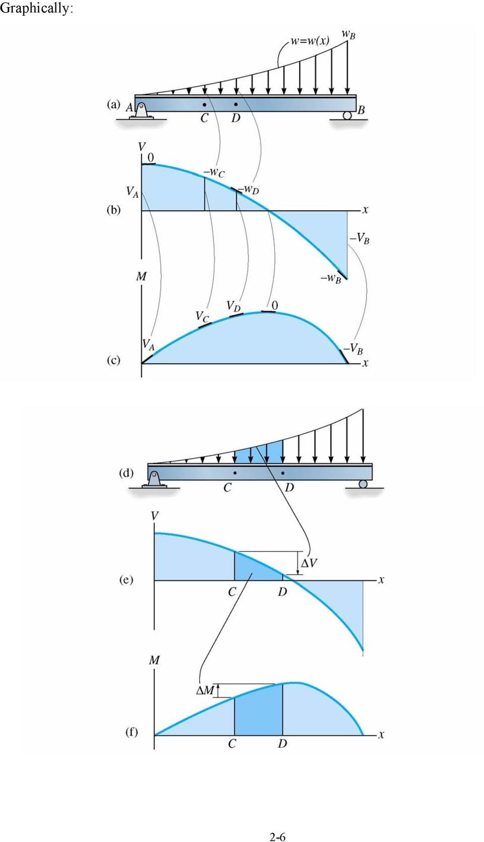
5 Mathematical Relationship Between External Loading, Internal Shear, and Internal Bending The previous example shows that: 1) axial force (and shear force) diagrams change abruptly at the location of a concentrated axial force (or applied force); 2) for a region of a beam without external applied forces, the shear force has a constant value, and the bending moment is a function of x; [see section AB of the beam in the previous example] 3) for a region of the beam subjected to a uniformly distributed load (UDL), the shear force is a function of x, and the bending moment is a function of x 2. [see section BC of the beam in the previous example]. In fact, we can prove that (see Section 6.2 of the textbook): dv ( x) dx = w( x) (2-1) i.e. the slope of the shear force diagram at x is equal to the negative of the value of the loading function at x; and, dm ( x) dx = V ( x) (2-2) i.e. the slope of the moment diagram at x is equal to the value of the shear function at x. dv ( x) From Eq. 2-1 we have: = w( x) through integration: dx (note what each side of the equation represents) From Eq. 2-2 we have through integration: (2-3). (note what each side of the equation represents) (2-4). 2-5
![AB of the beam in the previous example] 3) for a region of the beam subjected to a uniformly distributed load (UDL), the shear force is a function of x, and the bending moment is a function of x 2.](/docs-images/47/20816927/images/page_5.jpg "[see section BC of the beam in the previous example]. In fact, we can prove that (see Section 6.2 of the textbook): dv ( x) dx = w( x) (2-1) i.e. the slope of the shear force diagram at x is equal to the negative of the value of the loading function at x; and, dm ( x) dx = V ( x) (2-2) i.")
6 Graphically: 2-6
7 The following table, taken from your textbook, illustrates a number of common loading cases. It shows how shear and moment diagrams can be constructed on the basis of knowing the variation of the slope from the load and shear diagrams. Make sure that the relationships make sense, but you should not memorize the table!! You should always work from the basic relationships, Eqs. 2.1 to 2.4. (show overhead of table) 2-7

8 Graphical Method Example 1 Consider the cantilever beam subjected to the loading w(x). Draw the internal forces on a typical element of the beam, and hence derive the differential equations relating bending moments, shear forces, and applied loading, i.e. Eqs. 2-1, 2-2. Use these differential equations to draw shear force and bending moment diagrams for the following cases: (a) w(x) = 20 kn/m; (b) w(x) = 20x kn/m w(x) L (add soln from Campbell notes) 2-8
 w(x)")
9 2-9

10 Example Draw the shear force and bending moment diagrams. 35 kn/m 40 kn/m 1 m 2 m 3 m 2-10

11 2-11

12 Finally, we end this section with a discussion of torque diagrams. These are usually simpler than shear and bending moment diagrams, and can be illustrated with the following example. Example Draw the torque diagram for the cantilever shaft shown. Determine the maximum torque in the shaft. 1 m 1 m 1 m fixed end 5 knm 7 knm 12 knm 2-12

13 2-13

Shear Forces and Bending Moments
 Chapter 4 Shear Forces and Bending Moments 4.1 Introduction Consider a beam subjected to transverse loads as shown in figure, the deflections occur in the plane same as the loading plane, is called the
Mechanics of Materials. Chapter 4 Shear and Moment In Beams
 Mechanics of Materials Chapter 4 Shear and Moment In Beams 4.1 Introduction The term beam refers to a slender bar that carries transverse loading; that is, the applied force are perpendicular to the bar.
MECHANICS OF SOLIDS - BEAMS TUTORIAL 2 SHEAR FORCE AND BENDING MOMENTS IN BEAMS
 MECHANICS OF SOLIDS - BEAMS TUTORIAL 2 SHEAR FORCE AND BENDING MOMENTS IN BEAMS This is the second tutorial on bending of beams. You should judge your progress by completing the self assessment exercises.
ENGINEERING SCIENCE H1 OUTCOME 1 - TUTORIAL 3 BENDING MOMENTS EDEXCEL HNC/D ENGINEERING SCIENCE LEVEL 4 H1 FORMERLY UNIT 21718P
 ENGINEERING SCIENCE H1 OUTCOME 1 - TUTORIAL 3 BENDING MOMENTS EDEXCEL HNC/D ENGINEERING SCIENCE LEVEL 4 H1 FORMERLY UNIT 21718P This material is duplicated in the Mechanical Principles module H2 and those
Problem 1: Computation of Reactions. Problem 2: Computation of Reactions. Problem 3: Computation of Reactions
 Problem 1: Computation of Reactions Problem 2: Computation of Reactions Problem 3: Computation of Reactions Problem 4: Computation of forces and moments Problem 5: Bending Moment and Shear force Problem
Recitation #5. Understanding Shear Force and Bending Moment Diagrams
 Recitation #5 Understanding Shear Force and Bending Moment Diagrams Shear force and bending moment are examples of interanl forces that are induced in a structure when loads are applied to that structure.
Deflections. Question: What are Structural Deflections?
 Question: What are Structural Deflections? Answer: The deformations or movements of a structure and its components, such as beams and trusses, from their original positions. It is as important for the
Shear and Moment Diagrams. Shear and Moment Diagrams. Shear and Moment Diagrams. Shear and Moment Diagrams. Shear and Moment Diagrams
 CI 3 Shear Force and Bending oment Diagrams /8 If the variation of and are written as functions of position,, and plotted, the resulting graphs are called the shear diagram and the moment diagram. Developing
Shear Force and Moment Diagrams
 C h a p t e r 9 Shear Force and Moment Diagrams In this chapter, you will learn the following to World Class standards: Making a Shear Force Diagram Simple Shear Force Diagram Practice Problems More Complex
Structural Axial, Shear and Bending Moments
 Structural Axial, Shear and Bending Moments Positive Internal Forces Acting Recall from mechanics of materials that the internal forces P (generic axial), V (shear) and M (moment) represent resultants
BEAMS: SHEAR AND MOMENT DIAGRAMS (GRAPHICAL)
") LECTURE Third Edition BES: SHER ND OENT DIGRS (GRPHICL). J. Clark School of Engineering Department of Civil and Environmental Engineering 3 Chapter 5.3 by Dr. Ibrahim. ssakkaf SPRING 003 ENES 0 echanics
LECTURE Third Edition BES: SHER ND OENT DIGRS (GRPHICL). J. Clark School of Engineering Department of Civil and Environmental Engineering 3 Chapter 5.3 by Dr. Ibrahim. ssakkaf SPRING 003 ENES 0 echanics
Chapter 8. Shear Force and Bending Moment Diagrams for Uniformly Distributed Loads.
 hapter 8 Shear Force and ending Moment Diagrams for Uniformly Distributed Loads. 8.1 Introduction In Unit 4 we saw how to calculate moments for uniformly distributed loads. You might find it worthwhile
Analysis of Stresses and Strains
 Chapter 7 Analysis of Stresses and Strains 7.1 Introduction axial load = P / A torsional load in circular shaft = T / I p bending moment and shear force in beam = M y / I = V Q / I b in this chapter, we
CHAPTER 3 SHEARING FORCE AND BENDING MOMENT DIAGRAMS. Summary
 CHAPTER 3 SHEARING FORCE AND BENDING MOMENT DIAGRAMS Summary At any section in a beam carrying transverse loads the shearing force is defined as the algebraic sum of the forces taken on either side of
Module 2. Analysis of Statically Indeterminate Structures by the Matrix Force Method. Version 2 CE IIT, Kharagpur
 Module Analysis of Statically Indeterminate Structures by the Matrix Force Method esson 11 The Force Method of Analysis: Frames Instructional Objectives After reading this chapter the student will be able
COMPLEX STRESS TUTORIAL 3 COMPLEX STRESS AND STRAIN
 COMPLX STRSS TUTORIAL COMPLX STRSS AND STRAIN This tutorial is not part of the decel unit mechanical Principles but covers elements of the following sllabi. o Parts of the ngineering Council eam subject
8.2 Elastic Strain Energy
 Section 8. 8. Elastic Strain Energy The strain energy stored in an elastic material upon deformation is calculated below for a number of different geometries and loading conditions. These expressions for
Bending Stress in Beams
 936-73-600 Bending Stress in Beams Derive a relationship for bending stress in a beam: Basic Assumptions:. Deflections are very small with respect to the depth of the beam. Plane sections before bending
EDEXCEL NATIONAL CERTIFICATE/DIPLOMA MECHANICAL PRINCIPLES AND APPLICATIONS NQF LEVEL 3 OUTCOME 1 - LOADING SYSTEMS
 EDEXCEL NATIONAL CERTIFICATE/DIPLOMA MECHANICAL PRINCIPLES AND APPLICATIONS NQF LEVEL 3 OUTCOME 1 - LOADING SYSTEMS TUTORIAL 1 NON-CONCURRENT COPLANAR FORCE SYSTEMS 1. Be able to determine the effects
Chapter 5: Indeterminate Structures Slope-Deflection Method
 Chapter 5: Indeterminate Structures Slope-Deflection Method 1. Introduction Slope-deflection method is the second of the two classical methods presented in this course. This method considers the deflection
Approximate Analysis of Statically Indeterminate Structures
 Approximate Analysis of Statically Indeterminate Structures Every successful structure must be capable of reaching stable equilibrium under its applied loads, regardless of structural behavior. Exact analysis
ENGINEERING MECHANICS STATIC
 EX 16 Using the method of joints, determine the force in each member of the truss shown. State whether each member in tension or in compression. Sol Free-body diagram of the pin at B X = 0 500- BC sin
Beam Deflections: 4th Order Method and Additional Topics
 11 eam Deflections: 4th Order Method and dditional Topics 11 1 ecture 11: EM DEFECTIONS: 4TH ORDER METHOD ND DDITION TOICS TE OF CONTENTS age 11.1. Fourth Order Method Description 11 3 11.1.1. Example
MECHANICS OF SOLIDS - BEAMS TUTORIAL 1 STRESSES IN BEAMS DUE TO BENDING. On completion of this tutorial you should be able to do the following.
 MECHANICS OF SOLIDS - BEAMS TUTOIAL 1 STESSES IN BEAMS DUE TO BENDING This is the first tutorial on bending of beams designed for anyone wishing to study it at a fairly advanced level. You should judge
MCE380: Measurements and Instrumentation Lab. Chapter 9: Force, Torque and Strain Measurements
 MCE380: Measurements and Instrumentation Lab Chapter 9: Force, Torque and Strain Measurements Topics: Elastic Elements for Force Measurement Dynamometers and Brakes Resistance Strain Gages Holman, Ch.
Slide 10.1. Basic system Models
 Slide 10.1 Basic system Models Objectives: Devise Models from basic building blocks of mechanical, electrical, fluid and thermal systems Recognize analogies between mechanical, electrical, fluid and thermal
EDEXCEL NATIONAL CERTIFICATE/DIPLOMA MECHANICAL PRINCIPLES AND APPLICATIONS NQF LEVEL 3 OUTCOME 1 - LOADING SYSTEMS TUTORIAL 3 LOADED COMPONENTS
 EDEXCEL NATIONAL CERTIICATE/DIPLOMA MECHANICAL PRINCIPLES AND APPLICATIONS NQ LEVEL 3 OUTCOME 1 - LOADING SYSTEMS TUTORIAL 3 LOADED COMPONENTS 1. Be able to determine the effects of loading in static engineering
Design Analysis and Review of Stresses at a Point
 Design Analysis and Review of Stresses at a Point Need for Design Analysis: To verify the design for safety of the structure and the users. To understand the results obtained in FEA, it is necessary to
Stresses in Beam (Basic Topics)
") Chapter 5 Stresses in Beam (Basic Topics) 5.1 Introduction Beam : loads acting transversely to the longitudinal axis the loads create shear forces and bending moments, stresses and strains due to V and
Chapter 5 Stresses in Beam (Basic Topics) 5.1 Introduction Beam : loads acting transversely to the longitudinal axis the loads create shear forces and bending moments, stresses and strains due to V and
SOLID MECHANICS TUTORIAL MECHANISMS KINEMATICS - VELOCITY AND ACCELERATION DIAGRAMS
 SOLID MECHANICS TUTORIAL MECHANISMS KINEMATICS - VELOCITY AND ACCELERATION DIAGRAMS This work covers elements of the syllabus for the Engineering Council exams C105 Mechanical and Structural Engineering
STRESS AND DEFORMATION ANALYSIS OF LINEAR ELASTIC BARS IN TENSION
 Chapter 11 STRESS AND DEFORMATION ANALYSIS OF LINEAR ELASTIC BARS IN TENSION Figure 11.1: In Chapter10, the equilibrium, kinematic and constitutive equations for a general three-dimensional solid deformable
HØGSKOLEN I GJØVIK Avdeling for teknologi, økonomi og ledelse. Løsningsforslag for kontinuasjonseksamen i Mekanikk 4/1-10
 Løsningsforslag for kontinuasjonseksamen i 4/1-10 Oppgave 1 (T betyr tension, dvs. strekk, og C betyr compression, dvs. trykk.) Side 1 av 9 Leif Erik Storm Oppgave 2 Løsning (fra http://www.public.iastate.edu/~statics/examples/vmdiags/vmdiaga.html
Finite Element Simulation of Simple Bending Problem and Code Development in C++
 EUROPEAN ACADEMIC RESEARCH, VOL. I, ISSUE 6/ SEPEMBER 013 ISSN 86-48, www.euacademic.org IMPACT FACTOR: 0.485 (GIF) Finite Element Simulation of Simple Bending Problem and Code Development in C++ ABDUL
ENGINEERING COUNCIL CERTIFICATE LEVEL ENGINEERING SCIENCE C103 TUTORIAL 3 - TORSION
 ENGINEEING COUNCI CETIFICATE EVE ENGINEEING SCIENCE C10 TUTOIA - TOSION You should judge your progress by completing the self assessment exercises. These may be sent for marking or you may request copies
MECHANICS OF SOLIDS - BEAMS TUTORIAL TUTORIAL 4 - COMPLEMENTARY SHEAR STRESS
 MECHANICS OF SOLIDS - BEAMS TUTORIAL TUTORIAL 4 - COMPLEMENTARY SHEAR STRESS This the fourth and final tutorial on bending of beams. You should judge our progress b completing the self assessment exercises.
DESIGN OF SLABS. 3) Based on support or boundary condition: Simply supported, Cantilever slab,
 Based on support or boundary condition: Simply supported, Cantilever slab,") DESIGN OF SLABS Dr. G. P. Chandradhara Professor of Civil Engineering S. J. College of Engineering Mysore 1. GENERAL A slab is a flat two dimensional planar structural element having thickness small compared
DESIGN OF SLABS Dr. G. P. Chandradhara Professor of Civil Engineering S. J. College of Engineering Mysore 1. GENERAL A slab is a flat two dimensional planar structural element having thickness small compared
PLANE TRUSSES. Definitions
 Definitions PLANE TRUSSES A truss is one of the major types of engineering structures which provides a practical and economical solution for many engineering constructions, especially in the design of
Visualizing Differential Equations Slope Fields. by Lin McMullin
 Visualizing Differential Equations Slope Fields by Lin McMullin The topic of slope fields is new to the AP Calculus AB Course Description for the 2004 exam. Where do slope fields come from? How should
ME 343: Mechanical Design-3
 ME 343: Mechanical Design-3 Design of Shaft (continue) Dr. Aly Mousaad Aly Department of Mechanical Engineering Faculty of Engineering, Alexandria University Objectives At the end of this lesson, we should
Mohr s Circle. Academic Resource Center
 Mohr s Circle Academic Resource Center Introduction The transformation equations for plane stress can be represented in graphical form by a plot known as Mohr s Circle. This graphical representation is
Torsion Tests. Subjects of interest
 Chapter 10 Torsion Tests Subjects of interest Introduction/Objectives Mechanical properties in torsion Torsional stresses for large plastic strains Type of torsion failures Torsion test vs.tension test
ANALYTICAL METHODS FOR ENGINEERS
 UNIT 1: Unit code: QCF Level: 4 Credit value: 15 ANALYTICAL METHODS FOR ENGINEERS A/601/1401 OUTCOME - TRIGONOMETRIC METHODS TUTORIAL 1 SINUSOIDAL FUNCTION Be able to analyse and model engineering situations
Awell-known lecture demonstration1
 Acceleration of a Pulled Spool Carl E. Mungan, Physics Department, U.S. Naval Academy, Annapolis, MD 40-506; mungan@usna.edu Awell-known lecture demonstration consists of pulling a spool by the free end
Laterally Loaded Piles
 Laterally Loaded Piles 1 Soil Response Modelled by p-y Curves In order to properly analyze a laterally loaded pile foundation in soil/rock, a nonlinear relationship needs to be applied that provides soil
Torque and Rotational Equilibrium
 Torque and Rotational Equilibrium Name Section Torque is the rotational analog of force. If you want something to move (translation), you apply a force; if you want something to rotate, you apply a torque.
Analysis of Statically Determinate Trusses
 Analysis of Statically Determinate Trusses THEORY OF STRUCTURES Asst. Prof. Dr. Cenk Üstündağ Common Types of Trusses A truss is one of the major types of engineering structures which provides a practical
Rotation: Moment of Inertia and Torque
 Rotation: Moment of Inertia and Torque Every time we push a door open or tighten a bolt using a wrench, we apply a force that results in a rotational motion about a fixed axis. Through experience we learn
Statics problem solving strategies, hints and tricks
 Statics problem solving strategies, hints and tricks Contents 1 Solving a problem in 7 steps 3 1.1 To read.............................................. 3 1.2 To draw..............................................
Design of Steel Structures Prof. S.R.Satish Kumar and Prof. A.R.Santha Kumar
 Problem 1 Design a hand operated overhead crane, which is provided in a shed, whose details are: Capacity of crane = 50 kn Longitudinal spacing of column = 6m Center to center distance of gantry girder
Analysis of Stress CHAPTER 1 1.1 INTRODUCTION
 CHAPTER 1 Analysis of Stress 1.1 INTRODUCTION The basic structure of matter is characterized by nonuniformity and discontinuity attributable to its various subdivisions: molecules, atoms, and subatomic
Chapter 5A. Torque. A PowerPoint Presentation by Paul E. Tippens, Professor of Physics Southern Polytechnic State University
 Chapter 5A. Torque A PowerPoint Presentation by Paul E. Tippens, Professor of Physics Southern Polytechnic State University 2007 Torque is a twist or turn that tends to produce rotation. * * * Applications
2 Session Two - Complex Numbers and Vectors
 PH2011 Physics 2A Maths Revision - Session 2: Complex Numbers and Vectors 1 2 Session Two - Complex Numbers and Vectors 2.1 What is a Complex Number? The material on complex numbers should be familiar
Advanced Structural Analysis. Prof. Devdas Menon. Department of Civil Engineering. Indian Institute of Technology, Madras. Module - 5.3.
 Advanced Structural Analysis Prof. Devdas Menon Department of Civil Engineering Indian Institute of Technology, Madras Module - 5.3 Lecture - 29 Matrix Analysis of Beams and Grids Good morning. This is
Chapter 18 Static Equilibrium
 Chapter 8 Static Equilibrium 8. Introduction Static Equilibrium... 8. Lever Law... Example 8. Lever Law... 4 8.3 Generalized Lever Law... 5 8.4 Worked Examples... 7 Example 8. Suspended Rod... 7 Example
Torque and Rotary Motion
 Torque and Rotary Motion Name Partner Introduction Motion in a circle is a straight-forward extension of linear motion. According to the textbook, all you have to do is replace displacement, velocity,
Tower Cross Arm Numerical Analysis
 Chapter 7 Tower Cross Arm Numerical Analysis In this section the structural analysis of the test tower cross arm is done in Prokon and compared to a full finite element analysis using Ansys. This is done
Linear Motion vs. Rotational Motion
 Linear Motion vs. Rotational Motion Linear motion involves an object moving from one point to another in a straight line. Rotational motion involves an object rotating about an axis. Examples include a
Chapter 11 Equilibrium
 11.1 The First Condition of Equilibrium The first condition of equilibrium deals with the forces that cause possible translations of a body. The simplest way to define the translational equilibrium of
Mechanics of Materials. Chapter 5 Stresses In Beams
 Mechanics of Materials Chapter 5 Stresses In Beams 5.1 Introduction In previous chapters, the stresses in bars caused by axial loading and torsion. Here consider the third fundamental loading : bending.
F. P. Beer et al., Meccanica dei solidi, Elementi di scienza delle costruzioni, 5e - isbn 9788838668579, 2014 McGraw-Hill Education (Italy) srl
 srl") F. P. Beer et al., eccanica dei solidi, Elementi di scienza delle costruzioni, 5e - isbn 9788888579, 04 cgraw-hill Education (Italy) srl Reactions: Σ = 0: bp = 0 = Pb Σ = 0: ap = 0 = Pa From to B: 0
F. P. Beer et al., eccanica dei solidi, Elementi di scienza delle costruzioni, 5e - isbn 9788888579, 04 cgraw-hill Education (Italy) srl Reactions: Σ = 0: bp = 0 = Pb Σ = 0: ap = 0 = Pa From to B: 0
NPTEL STRUCTURAL RELIABILITY
 NPTEL Course On STRUCTURAL RELIABILITY Module # 0 Lecture Course Format: eb Instructor: Dr. Arunasis Chakraborty Department of Civil Engineering Indian Institute of Technology Guwahati . Lecture 0: System
The elements used in commercial codes can be classified in two basic categories:
 CHAPTER 3 Truss Element 3.1 Introduction The single most important concept in understanding FEA, is the basic understanding of various finite elements that we employ in an analysis. Elements are used for
Optimum proportions for the design of suspension bridge
 Journal of Civil Engineering (IEB), 34 (1) (26) 1-14 Optimum proportions for the design of suspension bridge Tanvir Manzur and Alamgir Habib Department of Civil Engineering Bangladesh University of Engineering
Finite Element Formulation for Beams - Handout 2 -
 Finite Element Formulation for Beams - Handout 2 - Dr Fehmi Cirak (fc286@) Completed Version Review of Euler-Bernoulli Beam Physical beam model midline Beam domain in three-dimensions Midline, also called
Designing a Structural Steel Beam. Kristen M. Lechner
 Designing a Structural Steel Beam Kristen M. Lechner November 3, 2009 1 Introduction Have you ever looked at a building under construction and wondered how the structure was designed? What assumptions
BASIC CONCEPTS AND CONVENTIONAL METHODS OF STUCTURAL ANALYSIS (LECTURE NOTES)
") BASIC CONCEPTS AND CONVENTIONA METHODS OF STUCTURA ANAYSIS (ECTURE NOTES) DR. MOHAN KAANI (Retired Professor of Structural Engineering) DEPARTMENT OF CIVI ENGINEERING INDIAN INSTITUTE OF TECHNOOGY (BOMBAY)
BASIC CONCEPTS AND CONVENTIONA METHODS OF STUCTURA ANAYSIS (ECTURE NOTES) DR. MOHAN KAANI (Retired Professor of Structural Engineering) DEPARTMENT OF CIVI ENGINEERING INDIAN INSTITUTE OF TECHNOOGY (BOMBAY)
Trigonometric Functions and Triangles
 Trigonometric Functions and Triangles Dr. Philippe B. Laval Kennesaw STate University August 27, 2010 Abstract This handout defines the trigonometric function of angles and discusses the relationship between
Introduction to Mechanical Behavior of Biological Materials
 Introduction to Mechanical Behavior of Biological Materials Ozkaya and Nordin Chapter 7, pages 127-151 Chapter 8, pages 173-194 Outline Modes of loading Internal forces and moments Stiffness of a structure
P4 Stress and Strain Dr. A.B. Zavatsky MT07 Lecture 3 Statically Indeterminate Structures
 4 Stress and Strain Dr... Zavatsky MT07 ecture 3 Statically Indeterminate Structures Statically determinate structures. Statically indeterminate structures (equations of equilibrium, compatibility, and
Chapter 1: Statics. A) Newtonian Mechanics B) Relativistic Mechanics
 Newtonian Mechanics B) Relativistic Mechanics") Chapter 1: Statics 1. The subject of mechanics deals with what happens to a body when is / are applied to it. A) magnetic field B) heat C ) forces D) neutrons E) lasers 2. still remains the basis of most
Chapter 1: Statics 1. The subject of mechanics deals with what happens to a body when is / are applied to it. A) magnetic field B) heat C ) forces D) neutrons E) lasers 2. still remains the basis of most
Use of Computers in Mechanics Education at Ohio State University*
 Int. J. Engng Ed. Vol. 16, No. 5, pp. 394±400, 2000 0949-149X/91 $3.00+0.00 Printed in Great Britain. # 2000 TEMPUS Publications. Use of Computers in Mechanics Education at Ohio State University* GEORGE
www.mathsbox.org.uk Displacement (x) Velocity (v) Acceleration (a) x = f(t) differentiate v = dx Acceleration Velocity (v) Displacement x
 Velocity (v) Acceleration (a) x = f(t) differentiate v = dx Acceleration Velocity (v) Displacement x") Mechanics 2 : Revision Notes 1. Kinematics and variable acceleration Displacement (x) Velocity (v) Acceleration (a) x = f(t) differentiate v = dx differentiate a = dv = d2 x dt dt dt 2 Acceleration Velocity
Mechanics 2 : Revision Notes 1. Kinematics and variable acceleration Displacement (x) Velocity (v) Acceleration (a) x = f(t) differentiate v = dx differentiate a = dv = d2 x dt dt dt 2 Acceleration Velocity
When the fluid velocity is zero, called the hydrostatic condition, the pressure variation is due only to the weight of the fluid.
 Fluid Statics When the fluid velocity is zero, called the hydrostatic condition, the pressure variation is due only to the weight of the fluid. Consider a small wedge of fluid at rest of size Δx, Δz, Δs
SHAFTS: TORSION LOADING AND DEFORMATION
 ECURE hird Edition SHAFS: ORSION OADING AND DEFORMAION A. J. Clark Shool of Engineering Department of Civil and Environmental Engineering 6 Chapter 3.1-3.5 by Dr. Ibrahim A. Assakkaf SPRING 2003 ENES 220
Shear Center in Thin-Walled Beams Lab
 Shear Center in Thin-Walled Beams Lab Shear flow is developed in beams with thin-walled cross sections shear flow (q sx ): shear force per unit length along cross section q sx =τ sx t behaves much like
Physics 9e/Cutnell. correlated to the. College Board AP Physics 1 Course Objectives
 Physics 9e/Cutnell correlated to the College Board AP Physics 1 Course Objectives Big Idea 1: Objects and systems have properties such as mass and charge. Systems may have internal structure. Enduring
Design Manual to BS8110
 Design Manual to BS8110 February 2010 195 195 195 280 280 195 195 195 195 195 195 280 280 195 195 195 The specialist team at LinkStudPSR Limited have created this comprehensive Design Manual, to assist
Mechanics lecture 7 Moment of a force, torque, equilibrium of a body
 G.1 EE1.el3 (EEE1023): Electronics III Mechanics lecture 7 Moment of a force, torque, equilibrium of a body Dr Philip Jackson http://www.ee.surrey.ac.uk/teaching/courses/ee1.el3/ G.2 Moments, torque and
SPECIFICATIONS, LOADS, AND METHODS OF DESIGN
 CHAPTER Structural Steel Design LRFD Method Third Edition SPECIFICATIONS, LOADS, AND METHODS OF DESIGN A. J. Clark School of Engineering Department of Civil and Environmental Engineering Part II Structural
Mechanics of Materials Summary
 Mechanics of Materials Summary 1. Stresses and Strains 1.1 Normal Stress Let s consider a fixed rod. This rod has length L. Its cross-sectional shape is constant and has area. Figure 1.1: rod with a normal
MODULE E: BEAM-COLUMNS
 MODULE E: BEAM-COLUMNS This module of CIE 428 covers the following subjects P-M interaction formulas Moment amplification Web local buckling Braced and unbraced frames Members in braced frames Members
4.2 Free Body Diagrams
 CE297-FA09-Ch4 Page 1 Friday, September 18, 2009 12:11 AM Chapter 4: Equilibrium of Rigid Bodies A (rigid) body is said to in equilibrium if the vector sum of ALL forces and all their moments taken about
Design MEMO 60 Reinforcement design for TSS 102
 Date: 04.0.0 sss Page of 5 CONTENTS PART BASIC ASSUMTIONS... GENERAL... STANDARDS... QUALITIES... 3 DIMENSIONS... 3 LOADS... 3 PART REINFORCEMENT... 4 EQUILIBRIUM... 4 Date: 04.0.0 sss Page of 5 PART BASIC
METHODS FOR ACHIEVEMENT UNIFORM STRESSES DISTRIBUTION UNDER THE FOUNDATION
 International Journal of Civil Engineering and Technology (IJCIET) Volume 7, Issue 2, March-April 2016, pp. 45-66, Article ID: IJCIET_07_02_004 Available online at http://www.iaeme.com/ijciet/issues.asp?jtype=ijciet&vtype=7&itype=2
EQUATIONS and INEQUALITIES
 EQUATIONS and INEQUALITIES Linear Equations and Slope 1. Slope a. Calculate the slope of a line given two points b. Calculate the slope of a line parallel to a given line. c. Calculate the slope of a line
The dynamic equation for the angular motion of the wheel is R w F t R w F w ]/ J w
![The dynamic equation for the angular motion of the wheel is R w F t R w F w ]/ J w](/thumbs/25/5134815.jpg "The dynamic equation for the angular motion of the wheel is R w F t R w F w ]/ J w") Chapter 4 Vehicle Dynamics 4.. Introduction In order to design a controller, a good representative model of the system is needed. A vehicle mathematical model, which is appropriate for both acceleration
Chapter 4 Vehicle Dynamics 4.. Introduction In order to design a controller, a good representative model of the system is needed. A vehicle mathematical model, which is appropriate for both acceleration
Design MEMO 54a Reinforcement design for RVK 41
 Page of 5 CONTENTS PART BASIC ASSUMTIONS... 2 GENERAL... 2 STANDARDS... 2 QUALITIES... 3 DIMENSIONS... 3 LOADS... 3 PART 2 REINFORCEMENT... 4 EQUILIBRIUM... 4 Page 2 of 5 PART BASIC ASSUMTIONS GENERAL
INTRODUCTION TO BEAMS
 CHAPTER Structural Steel Design LRFD Method INTRODUCTION TO BEAMS Third Edition A. J. Clark School of Engineering Department of Civil and Environmental Engineering Part II Structural Steel Design and Analysis
16. Beam-and-Slab Design
 ENDP311 Structural Concrete Design 16. Beam-and-Slab Design Beam-and-Slab System How does the slab work? L- beams and T- beams Holding beam and slab together University of Western Australia School of Civil
Shaft- Mounted Speed Reducers
 Torque Arm Design Considerations for Todd R. Bobak has worked in the gear industry for 15 years. He has held positions in technical service, design and development, and quality assurance. He is a product
Structural Analysis - II Prof. P. Banerjee Department of Civil Engineering Indian Institute of Technology, Bombay. Lecture - 02
 Structural Analysis - II Prof. P. Banerjee Department of Civil Engineering Indian Institute of Technology, Bombay Lecture - 02 Good morning. Today is the second lecture in the series of lectures on structural
FOOTING DESIGN EXAMPLE
 County: Any Design: BRG Date: 10/007 Hwy: Any Ck Dsn: BRG Date: 10/007 FOOTING DESIGN EXAMPLE Design: Based on AASHTO LRFD 007 Specifications, TxDOT LRFD Bridge Design Manual, and TxDOT Project 0-4371
Section 16: Neutral Axis and Parallel Axis Theorem 16-1
 Section 16: Neutral Axis and Parallel Axis Theorem 16-1 Geometry of deformation We will consider the deformation of an ideal, isotropic prismatic beam the cross section is symmetric about y-axis All parts
Stress Analysis, Strain Analysis, and Shearing of Soils
 C H A P T E R 4 Stress Analysis, Strain Analysis, and Shearing of Soils Ut tensio sic vis (strains and stresses are related linearly). Robert Hooke So I think we really have to, first, make some new kind
Gear Trains. Introduction:
 Gear Trains Introduction: Sometimes, two or more gears are made to mesh with each other to transmit power from one shaft to another. Such a combination is called gear train or train of toothed wheels.
CLASSICAL STRUCTURAL ANALYSIS
 Table of Contents CASSCA STRUCTURA ANAYSS... Conjugate beam method... External work and internal work... 3 Method of virtual force (unit load method)... 5 Castigliano s second theorem... Method of consistent
9.3 Two-way Slabs (Part I)
") 9.3 Two-way Slabs (Part I) This section covers the following topics. Introduction Analysis and Design Features in Modeling and Analysis Distribution of Moments to Strips 9.3.1 Introduction The slabs are
9.3 Two-way Slabs (Part I) This section covers the following topics. Introduction Analysis and Design Features in Modeling and Analysis Distribution of Moments to Strips 9.3.1 Introduction The slabs are