Switches and Indicators 61
|
|
|
- Allen Shaw
- 9 years ago
- Views:
Transcription
1 Switchs and Indicators 61 61
2 Switchs and Indicators Indx Sris 61 Dscription Pag 109 Product Assmbly Pag 110 Product Rang - pushbuttons for standard mounting - pushbuttons for flush mounting - assccoris / spar parts Tchnical Data Pag 111 Pag 117 Pag 123 Pag 137 Tchnical Drawing / Dimnsion / Layouts Pag 140 Circuit Drawing Pag 150 Typical Applications Pag 151 Marking Pag

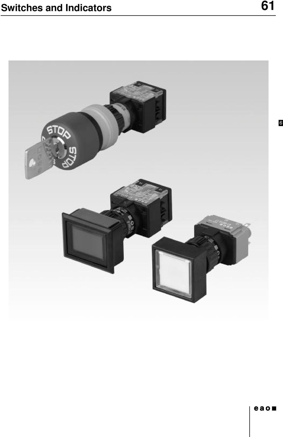
3 Dscription 61 Gnral Nots Th indicators, illuminatd pushbuttons, slctor switchs, kylock switchs and mrgncy stop switchs with spray-watr protction at th front (IP 65) ar modular and consist of an actuator and switching lmnt. In addition to th standard switching lmnts (gold-platd silvr contact with univrsal soldring or plug-in trminals), forcdopning, slow-mak switching lmnts with gold or silvr contacts and soldring or plug-in trminals ar availabl. Thy can b supplid with scrw trminals and silvr contacts too. Th front dimnsions of th units in this sris ar 24 x 24 mm, 24 mm dia., 18 x 24 mm, 18 x 18 mm or 18 mm dia. For flush mounting th dimnsions 25 mm dia., 24 x 30 mm and 24 x 24 mm can b supplid. Mounting All switch actuators ar mountd from th front by pushing thm through th mounting hol in th front panl. Thy ar thn fixd from th back with a fixing nut and th mounting tool typ no Max. tightning torqu 50 Ncm. For mounting dimnsions and grid siz s as of pag 145. Th prassmbld switching lmnt with th conncting wirs in a singl plan can b clippd on aftrwards. For block or sris mounting aids ar availabl. For switching lmnts with 2.8 mm plug-in trminals, w offr plugin bass, which whn soldrd to a PCB nabl a plug-in connction to th button. All actuators ar providd with an anti-rotation dvic. Kylock switch Standard lock (indx D) 1 standard numbr 311. If th lock numbr is not spcifid, w will supply no An additional 134 spcial locks (indx X) ar availabl on rqust. Mastr kys for locks no may b ordrd by quoting no Two kys ar supplid with ach kylock switch. Spar kys for DOM standard locks may b ordrd by quoting no (plas stat th lock numbr). Emrgncy stop switch foolproof with ky to unlock Kaba safty lock. Standard lock numbr is Locks with othr numbrs ar availabl on rqust. Spar kys for KABA locks may b ordrd undr no (plas stat th lock numbr). Spcimn ordr Indicator complt - indicator complt, soldring trminal, 18 x 24 mm Rcommndd accssoris: - lns plastic, 18 x 24 mm, clar LED, 6 chips, 6 VDC, yllow Lnss Th flat or concav lnss ar availabl in various colours and a transparnt or translucnt vrsion. Th lns surfac is non-rflcting (matt). Lnss 19.7 mm dia. can b supplid also in aluminium. Marking For ngraving, hot stamping and film insrts, s pag 153 undr Marking. Illumination Th midgt-groovd T 1 3/4 incandscnt lamp (6-60 V, 1.2 W) nsurs prfct illumination of th lnss, which ar supplid in various colours. Midgt-groovd T 1 3/4 Multi-LED (6, 12, 24, 48 V) ar also availabl in whit, rd, yllow and grn. For supply voltags abov 60 V, it is ncssary to us a voltag rduction lmnt (xtrnal sris rsistor, capacitor or transformr). Do not soldr th trminals dirctly, bacaus of th high surfac tmpratur. Position indication Whn th switch with maintaind action is actuatd, th lns snaps into plac mchanically. Th position of contacts can always b dtrmind by th position of th lns. 109

4 Product Assmbly 61 illuminatd-/pushbutton 1 lns 2 actuator cas 3 fixing nut 4 switching lmnt illuminatd-/pushbutton for flush mounting 1 lns 2 acutator housing 3 front bzl 4 saling 5 front panl 6 fixing bow 7 fixing nut 8 switching lmnt 110

5 Pushbuttons for Standard Mounting 61 indicator complt rcommndd accssoris: d lns plastic 123 d front ring 126 d incandscnt lamp 132; LED 133 connction mthod a 18 x 24 mm b 24 x 24 mm 18 mm dia. b 18 x 18 mm 24 mm dia. indicator complt ST/PT ,005 circuit drawing tchnical drawing mounting dimnsion 61 connction mthod: ST/PT = soldring-/plug-in trminal Accssori front ring only rqustd for Ø 24 mm. marking s pag 153 tchnical drawing as of pag 140, mounting dimnsions as of pag 145, circuit drawing as of pag 150 indicator-/flashr-actuator rcommndd accssoris: d lns plastic 123 d front ring 126 d incandscnt lamp 132; LED 133 d lamp lmnt 128; diod lmnt 128; flashr lmnt 131 a 18 x 24 mm b 24 x 24 mm 18 mm dia. b 18 x 18 mm Accssori front ring only rqustd for Ø 24 mm. marking s pag 153 tchnical drawing as of pag 140, mounting dimnsions as of pag 145, circuit drawing as of pag mm dia. indicator-/flashr-actuator ,005 circuit drawing tchnical drawing mounting dimnsion 111

6 Pushbuttons for Standard Mounting 61 illuminatd-/pushbutton actuator rcommndd accssoris: d lns plastic 123; lns mtal with window 124; lns mtal 124 d front ring 126 d incandscnt lamp 132; LED 133 d switching lmnt for illuminatd-/pushbutton, kylock-/slctor switch 2 positions 129 switching action a 18 x 24 mm b 24 x 24 mm 18 mm dia. b 18 x 18 mm 24 mm dia. illuminatd-/pushbutton actuator main ,005 mom ,005 mom/main ,005 circuit drawing tchnical drawing mounting dimnsion switching action: main = maintaind action, mom = momntary action, mom/main = momntary-/maintaind action Accssori front ring only rqustd for Ø 24 mm. marking s pag 153 tchnical drawing as of pag 140, mounting dimnsions as of pag 145, circuit drawing as of pag 150 mrgncy stop switch actuator foolproof according to EN 418 rcommndd accssoris: d labl for mrgncy stop switch 134 d switching lmnt for mrgncy stop switch 130 d protctiv shroud for mrgncy stop switch 134 switching action 27 mm dia. unlocking marking of mushroom-had cap mrgncy stop switch actuator foolproof main twist to rlas arrows / ,003 stop / ,003 without labl main ky to rlas stop /K ,038 standard lock1001, othr lock numbrs on rqust circuit drawing tchnical drawing mounting dimnsion switching action: main = maintaind action dscription s pag 109 tchnical drawing as of pag 140, mounting dimnsions as of pag 145, circuit drawing as of pag

7 Pushbuttons for Standard Mounting 61 pushbutton actuator with mushroom-had cap rcommndd accssoris: d mushroom-had cap 124 d front ring 126 d switching lmnt for illuminatd-/pushbutton, kylock-/slctor switch 2 positions mm dia. pushbutton actuator with mushroom-had cap main ,006 mom ,006 switching action circuit drawing tchnical drawing mounting dimnsion 61 switching action: main = maintaind action, mom = momntary action tchnical drawing as of pag 140, mounting dimnsions as of pag 145, circuit drawing as of pag 150 kylock switch actuator 2 positions if installd with anti-twist dvic, th lug is on th lft. rcommndd accssoris: d kylock front bzl 124 d switching lmnt for illuminatd-/pushbutton, kylock-/slctor switch 2 positions 129 d anti-twisting ring 135 maint. 90 C A mom. 42 kylock switch actuator 2 positions pos. A: basic position pos. C: maintaind action standard lock 311, othr lock numbrs on rqust pos. A: basic position pos. C: momntary action standard lock 311, othr lock numbrs on rqust C A switching action ky rmovabl in main A /D ,003 C /D ,003 C+A /D ,003 mom A /D ,003 circuit drawing tchnical drawing mounting dimnsion switching action: main = maintaind action, mom = momntary action dscription s pag 109 tchnical drawing as of pag 140, mounting dimnsions as of pag 145, circuit drawing as of pag

8 Pushbuttons for Standard Mounting 61 kylock switch actuator 3 positions if installd with anti-twist dvic, th lug is on th lft. rcommndd accssoris: d kylock front bzl 124 d switching lmnt for kylock-/slctor switch 3 positions 130 d anti-twisting ring 135 maint. 90 C A B mom. 42 kylock switch actuator 3 positions pos. C: maintaind action pos. A: basic position pos. B: maintaind action standard lock 311 othr lock numbrs on rqust pos. C: maintaind action pos. A: basic position pos. B: momntary action standard lock 311 othr lock numbrs on rqust pos. C: momntary action pos. A: basic position pos. B: maintaind action standard lock 311 pos. C: momntary action pos. A: basic position pos. B: momntary action standard lock 311 C A B switching action ky rmovabl in main-0-main A /D ,003 A+B /D ,003 B /D ,003 C /D ,003 C+A /D ,003 C+A+B /D ,003 C+B /D ,003 main-0-mom A /D ,003 C /D ,003 C+A /D ,003 mom-0-main A /D ,003 A+B /D ,003 B /D ,003 mom-0-mom A /D ,003 circuit drawing tchnical drawing mounting dimnsion switching action: mom = momntary action, main = maintaind action, 0 = basic position dscription s pag 109 tchnical drawing as of pag 140, mounting dimnsions as of pag 145, circuit drawing as of pag

9 Pushbuttons for Standard Mounting 61 slctor switch actuator 2 positions if installd with anti-twist dvic, th lug is on th lft. rcommndd accssoris: d lvr 125 d incandscnt lamp 132; LED 133 d switching lmnt for illuminatd-/pushbutton, kylock-/slctor switch 2 positions 129 d anti-twisting ring 135 maint. 90 C A mom. 42 slctor switch actuator 2 positions pos. C: maintaind action pos. A: basic position pos. C: momntary action pos. A: basic position C A switching action circuit drawing tchnical drawing mounting dimnsion 18 mm dia. main ,006 mom , switching action: main = maintaind action, mom = momntary action tchnical drawing as of pag 140, mounting dimnsions as of pag 145, circuit drawing as of pag

10 Pushbuttons for Standard Mounting 61 slctor switch actuator 3 positions if installd with anti-twist dvic, th lug is on th lft. rcommndd accssoris: d lvr 125 d incandscnt lamp 132; LED 133 d switching lmnt for kylock-/slctor switch 3 positions 130 d anti-twisting ring 135 maint. 90 C A B mom. 42 slctor switch actuator 3 positions pos. C: maintaind action pos. A: basic position pos. B: maintaind action pos. C: maintaind action pos. A: basic position pos. B: momntary action pos. C: momntary action pos. A: basic position pos. B: maintaind action pos. C: momntary action pos. A: basic position pos. B: momntary action C A B switching action circuit drawing tchnical drawing mounting dimnsion 18 mm dia. main-0-main ,006 main-0-mom ,006 mom-0-main ,006 mom-0-mom ,006 switching action: mom = momntary, main = maintaining, 0 = basic position tchnical drawing as of pag 140, mounting dimnsions as of pag 145, circuit drawing as of pag

11 Pushbuttons for Flush Mounting 61 indicator complt for flush mounting rcommndd accssoris: d lns plastic for flush mounting 124 d front bzl-st for flush mounting 126 d incandscnt lamp 132; LED 133 indicator complt for flush mounting ST/PT ,006 connction mthod circuit drawing tchnical drawing mounting dimnsion 61 connction mthod: ST/PT = soldring-/plug-in trminal marking s pag 153 tchnical drawing as of pag 140, mounting dimnsions as of pag 145, circuit drawing as of pag 150 indicator-/flashr-actuator for flush mounting rcommndd accssoris: d lns plastic for flush mounting 124 d front bzl-st for flush mounting 126 d incandscnt lamp 132; LED 133 d lamp lmnt 128; diod lmnt 128; flashr lmnt 131 indicator-/flashr-actuator for flush mounting ,005 marking s pag 153 tchnical drawing as of pag 140, mounting dimnsions as of pag 145, circuit drawing as of pag 150 circuit drawing tchnical drawing mounting dimnsion 117

12 Pushbuttons for Flush Mounting 61 illuminatd-/pushbutton actuator for flush mounting rcommndd accssoris: d lns plastic for flush mounting 124; lns mtal with window 124; lns mtal 124 d front bzl-st for flush mounting 126 d incandscnt lamp 132; LED 133 d switching lmnt for illuminatd-/pushbutton, kylock-/slctor switch 2 positions 129 illuminatd-/pushbutton actuator for flush mounting mom/main ,005 mom ,005 main ,005 switching action circuit drawing tchnical drawing mounting dimnsion switching action: main = maintaind action, mom = momntary action, mom/main = momntary-/maintaind action marking s pag 153 tchnical drawing as of pag 140, mounting dimnsions as of pag 145, circuit drawing as of pag 150 mushroom pushbutton actuator for flush mounting, rcommndd accssoris: d mushroom-had cap 124 d front bzl-st round for flush mounting 126 d switching lmnt for illuminatd-/pushbutton, kylock-/slctor switch 2 positions 129 mushroom pushbutton actuator for flush mounting mom/main ,006 mom ,006 main ,006 switching action circuit drawing tchnical drawing mounting dimnsion switching action: main = maintaind action, mom = momntary action, mom/main = momntary-/maintaind action tchnical drawing as of pag 140, mounting dimnsions as of pag 145, circuit drawing as of pag

13 Pushbuttons for Flush Mounting 61 kylock switch actuator with 2 positions for flush mounting rcommndd accssoris: d kylock front bzl 124 d front bzl-st for flush mounting 126 d switching lmnt for illuminatd-/pushbutton, kylock-/slctor switch 2 positions 129 maint. 90 C A mom. 42 C A kylock switch actuator with 2 positions for flush mounting pos. A: basic position pos. C: maintaind action standard lock 311, othr lock numbrs on rqust pos. A: basic position pos. C: momntary action standard lock 311, othr lock numbrs on rqust switching action ky rmovabl in main A /D ,003 C /D ,003 C+A /D ,003 mom A /D ,003 circuit drawing tchnical drawing mounting dimnsion 61 switching action: main = maintaind action, mom = momntary action dscription s pag 109 tchnical drawing as of pag 140, mounting dimnsions as of pag 145, circuit drawing as of pag

14 Pushbuttons for Flush Mounting 61 kylock switch actuator 3 positions for flush mounting rcommndd accssoris: d kylock front bzl 124 d front bzl-st for flush mounting 126 d switching lmnt for kylock-/slctor switch 3 positions 130 maint. 90 C A B mom. 42 kylock switch actuator 3 positions for flush mounting pos. C: maintaind action pos. A: basic position Pos. B: momntary action standard lock 311, othr lock numbrs on rqust pos. C: maintaind action pos. A: basic position pos. B: maintaind action standard lock 311, othr lock numbrs on rqust pos. C: momntary action pos. A: basic position pos. B: maintaind action standard lock 311, othr lock numbrs on rqust pos. C: momntary action pos. A: basic position pos. B: momntary action standard lock 311, othr lock numbrs on rqust C A B switching action ky rmovabl in main-0-mom A /D ,003 C /D ,003 C+A /D ,003 main-0-main A /D ,003 A+B /D ,003 B /D ,003 C /D ,003 C+A /D ,003 C+A+B /D ,003 C+B /D ,003 mom-0-main A /D ,003 A+B /D ,003 B /D ,003 mom-0-mom A /D ,003 circuit drawing tchnical drawing mounting dimnsion switching action: mom = momntary action, main = maintaind action, 0 = basic position dscription s pag 109 tchnical drawing as of pag 140, mounting dimnsions as of pag 145, circuit drawing as of pag

15 Pushbuttons for Flush Mounting 61 slctor switch actuator 2 positions for flush mounting rcommndd accssoris: d lvr for flush mounting 125 d front bzl-st for flush mounting 126 d incandscnt lamp 132; LED 133 d switching lmnt for illuminatd-/pushbutton, kylock-/slctor switch 2 positions 129 maint. 90 C A mom. 42 C A slctor switch actuator 2 positions for flush mounting pos. C: maintaind action pos. A: basic position pos. C: momntary action pos. A: basic position switching action circuit drawing tchnical drawing mounting dimnsion main ,006 mom , switching action: main = maintaind action, mom = momntary action tchnical drawing as of pag 140, mounting dimnsions as of pag 145, circuit drawing as of pag

16 Pushbuttons for Flush Mounting 61 slctor switch actuator 3 positions for flush mounting rcommndd accssoris: d lvr for flush mounting 125 d front bzl-st for flush mounting 126 d incandscnt lamp 132; LED 133 d switching lmnt for kylock-/slctor switch 3 positions 130 maint. 90 C A B mom. 42 C A B slctor switch actuator 3 positions for flush mounting pos. C: maintaind action pos. A: basic position pos. B: maintaind action pos. C: maintaind action pos. A: basic position pos. B: momntary action pos. C: momntary action pos. A: basic position pos. B: maintaind action pos. C: momntary action pos. A: basic position pos. B: momntary action switching action circuit drawing tchnical drawing mounting dimnsion main-0-main ,006 main-0-mom ,006 mom-0-main ,006 mom-0-mom ,006 switching action: mom = momntary, main = maintaining, 0 = basic position tchnical drawing as of pag 140, mounting dimnsions as of pag 145, circuit drawing as of pag

17 Accssoris 61 at front lns plastic lns plastic matt matt (not for film insrt and LED) lns/support transparnt/translucnt shap concav flat flat matt (not for film insrt and illumination) concav flat concav translucnt/ translucnt translucnt/ translucnt opaqu/ translucnt opaqu/ translucnt a b b 18 x 24 mm 24 x 24 mm 18 mm dia. 18 x 18 mm 25 mm dia. colour blu ,001 colourlss, ,001 clar grn ,001 orang ,001 rd ,001 yllow ,001 blu , , ,001 transparnt/translucnt colourlss, clar , , ,001 grn , ,002 orang , , ,001 rd , , ,001 smokd , , ,001 yllow , ,001 whit ,001 whit ,001 black ,001 gry ,001 black ,001 gry ,

18 Accssoris 61 lns plastic for flush mounting lns plastic for flush mounting matt matt (not for film insrt and LED) matt (not for film insrt and illumination) shap lns/support colour flat transparnt/translucnt a 24 x 30 mm b 24 x 24 mm 25 mm dia. blu ,001 colourlss, clar ,001 grn ,001 orang ,001 rd ,001 smokd ,001 yllow ,001 flat translucnt/translucnt whit ,001 flat opaqu/translucnt black ,001 gry ,001 lns mtal with window lns mtal with window matt 25 mm dia. shap lns colour flat aluminium anodizd natural A 0,002 lns mtal lns mtal matt 25 mm dia. shap lns colour flat aluminium anodizd black ,002 blu ,002 grn ,002 natural ,002 rd ,002 yllow ,002 mushroom-had cap mushroom-had cap plastic 32 mm dia. mushroom colour opaqu black ,004 grn ,004 rd ,004 yllow ,004 kylock front bzl for kylock switch actuator a b b 18 x 24 mm 24 x 24 mm 18 mm dia. 18 x 18 mm kylock front bzl , not for flush mounting 124

19 Accssoris 61 lvr lvr with marking dot and transparnt bar colour colour of bar black black, opaqu ,001 blu ,001 grn ,001 orang ,001 rd ,001 whit, opaqu ,001 yllow ,001 gry blu ,001 grn ,001 gry, opaqu ,001 orang ,001 rd ,001 whit, opaqu ,001 yllow , lvr for flush mounting lvr for flush mounting with marking dot and transparnt bar colour colour of bar black black, opaqu ,001 blu ,001 grn ,001 orang ,001 rd ,001 whit, opaqu ,001 yllow ,001 gry blu ,001 grn ,001 gry, opaqu ,001 orang ,001 rd ,001 whit, opaqu ,001 yllow ,001 marking plat for lns round, marking plat clar, of plastic, can b hot prssd front shap marking plat colour round transparnt clar ,001 front bzl for slctor switch squar front b b 24 x 24 mm 26 x 26 mm matrial colour front bzl plastic black ,

20 Accssoris 61 front bzl-st for flush mounting front bzl-st for flush mounting a b 24 x 30 mm 24 x 24 mm Ø25mm us matrial colour illuminatd aluminium natural ,006 pushbutton/indicator anodizd black ,007 plastic aluminium ,007 platd black ,006 kylock switch aluminium natural ,007 anodizd black ,007 plastic aluminium ,007 platd black ,006 slctor switch aluminium natural ,006 anodizd black ,007 plastic ,007 front ring for actuator 24 mm dia. matrial colour front ring aluminium anodizd black ,003 natural ,003 protctiv front mmbran cap for actuator 24 mm dia. matrial colour protctiv front mmbran cap silicon natur transparnt ,001 protctiv front mmbran cap for flush mounting protctiv front mmbran cap for flush mounting for front bzl-st for flush mounting matrial colour silicon natur transparnt ,001 protctiv covr protctiv covr hingd, transparnt, with mans for saling a 18 x 24 mm b 18 x 18 mm b 24 x 24 mm tchnical drawing , , ,005 tchnical drawing as of pag

21 Accssoris 61 protctiv covr for flush mounting protctiv covr for flush mounting hingd, transparnt, with mans for saling a 24 x 30 mm b 24 x 24 mm ,006 blind plug projcting 61 blind plug projcting for mounting hol 16 mm dia. a b b 18 x 24 mm 24 x 24 mm 18 mm dia. 18 x 18 mm colour black ,003 mounting dimnsion mounting dimnsions as of pag 145 blind plug flat a b 24 x 30 mm 24 x 24 mm 28 mm dia. colour blind plug flat black ,006 for mounting hol 21 x 21 mm for mounting hol 21 x 27 mm black ,006 for mounting hol 22.5 mm dia. black ,006 mounting dimnsion mounting dimnsions as of pag
22 Accssoris 61 EMC ky protction cap EMC ky protction cap plastic black, for lock typ DOM spar ky spar ky for mrgncy stop switch with ky to rlas, lock typ KABA standard lock 1001, othr lock numbrs on rqust for kylock switch, lock typ DOM standard lock 311, othr lock numbrs on rqust , ,006 dscription s pag 109 mastr ky mastr ky for lock numbrs ,006 at back lamp lmnt lamp lmnt with scrw trminal circuit drawing ,005 circuit drawing as of pag 150 diod lmnt diod lmnt with soldring-/plug-in trminal numbr of diods circuit drawing componnts layout , ,008 componnts layouts as of pag 146, circuit drawing as of pag
23 Accssoris 61 switching lmnt for illuminatd-/pushbutton, kylock-/slctor switch 2 positions switching lmnt for illuminatd-/pushbutton, kylock-/ slctor switch 2 positions with lamp trminal, max. 250 VAC/6A with lamp trminal, max. 42 VAC/DC/100 ma with lamp trminal, max.250 VAC/5A without lamp trminal, max. 250 VAC/6 A diod (1N 4007) switching systm contacts connction mthod matrial of contacts - SA 1NC ST/PT gold/silvr ,007 silvr ,007 1NC + 1NO ST/PT gold/silvr ,007 silvr ,007 1NC + 2NO ST/PT gold/silvr ,007 silvr ,007 1NO ST/PT gold/silvr ,007 silvr ,007 2NC ST/PT gold/silvr ,007 silvr ,007 2NC + 1NO ST/PT gold/silvr ,007 silvr ,007 2NO ST/PT gold/silvr ,007 silvr ,007 3NC ST/PT gold/silvr ,007 silvr ,007 3NO ST/PT gold/silvr ,007 silvr ,007 T 1NC SCH silvr ,008 1NO SCH silvr ,008 2 SA 1NO + 2D ST/PT silvr ,007 1NO + 2D ST/PT gold/silvr ,007 - T 1NC ST/PT gold ,008 1NC + 1NO ST/PT gold ,008 1NO ST/PT gold ,008 2NC ST/PT gold ,008 2NO ST/PT gold ,008 - T 1NC ST/PT silvr ,008 1NC + 1NO ST/PT silvr ,008 1NO ST/PT silvr ,008 2NC ST/PT silvr ,008 2NO ST/PT silvr ,008 - T 1NC SCH silvr ,008 1NC + 1NO SCH silvr ,008 1NO SCH silvr ,008 2NC SCH silvr ,008 2NO SCH silvr ,008 circuit drawing componnts layout 61 switching systm: SA = snap-action switching lmnt, T = slow-mak switching lmnt connction mthod: SCH = scrw trminal, ST/PT = soldring-/plug-in trminal contacts: NC = normally closd, NO = normally opn componnts layouts as of pag 146, circuit drawing as of pag
24 Accssoris 61 switching lmnt for mrgncy stop switch switching systm contacts connction mthod matrial of contacts switching lmnt for mrgncy T 1NC ST/PT silvr ,008 stop switch 1NC + 1NO ST/PT silvr ,008 max. 250 VAC/5A 2NC ST/PT silvr ,008 max. 250 VAC/6A T 1NC SCH silvr ,008 1NC + 1NO SCH silvr ,008 2NC SCH silvr ,008 max. 42 VAC/DC/100 ma T 1NC ST/PT gold ,008 1NC + 1NO ST/PT gold ,008 2NC ST/PT gold ,008 circuit drawing componnts layout switching systm: T = slow-mak switching lmnt connction mthod: SCH = scrw trminal, ST/PT = soldring-/plug-in trminal contacts: NC = normally closd, NO = normally opn componnts layouts as of pag 146, circuit drawing as of pag 150 switching lmnt for kylock-/slctor switch 3 positions switching lmnt for kylock-/ slctor switch 3 positions with lamp trminal, max. 250 VAC/ 6A with lamp trminal, max. 42 VAC/ DC/100 ma with lamp trminal, max.250 VAC/ 5A without lamp trminal, max. 250 VAC/6 A switching systm contacts connction mthod matrial of contacts SA 1NC + 1NO ST/PT gold/silvr ,008 silvr ,008 2NC ST/PT gold/silvr ,008 silvr ,008 2NO ST/PT gold/silvr ,008 silvr ,008 T 1NC + 1NO ST/PT gold ,008 2NC ST/PT gold ,008 2NO ST/PT gold ,008 T 1NC + 1NO ST/PT silvr ,008 2NC ST/PT silvr ,008 2NO ST/PT silvr ,008 T 1NC + 1NO SCH silvr ,008 2NC SCH silvr ,008 2NO SCH silvr ,008 circuit drawing componnts layout switching systm: SA = snap-action switching lmnt, T = slow-mak switching lmnt connction mthod: SCH = scrw trminal, ST/PT = soldring-/plug-in trminal contacts: NC = normally closd, NO = normally opn componnts layouts as of pag 146, circuit drawing as of pag
25 Accssoris 61 flashr lmnt opration voltag flashr lmnt 12 VAC/DC - 28 VAC/DC ST connction mthod connction mthod: ST = soldring trminal typical applications s pag 151 circuit drawing as of pag 150 PCB plug-in bas for plug-in trminal 61 for pin orintation PCB plug-in bas indicator complt axial , mm dia. x 12.8 mm 15 mm x 23 mm x 9.4 mm slow-mak switching lmnt axial , mm x 23.6 mm x 10.9 mm snap-action switching lmnt axial ,003 componnts layout componnts layouts as of pag 146 multi-plug housing multi-plug housing for snap-action switching lmnt, max. 6 connctions possibl ,002 cabl sho connction mthod cabl sho plug in trminal 2,8 x 0,5 mm ,001 plug-in trminal 2,8 x 0,5 mm for multi-plug housing ,
26 Accssoris 61 trminal covr us trminal covr for indicator lmnt ,001 for snap-action switching lmnt ,002 for illumination incandscnt lamp incandscnt lamp bas MG T 1 3/4 voltag/currnt 6 AC/DC/125 ma ( ) 0, AC/DC/200 ma ( ) 0, AC/DC/75 ma ( ) 0, AC/DC/80 ma ( ) 0, AC/DC/40 ma ( ) 0, AC/DC/35 ma ( ) 0, AC/DC/30 ma ( ) 0, AC/DC/40 ma ( ) 0, AC/DC/20 ma ( ) 0, AC/DC/30 ma ( ) 0, AC/DC/20 ma ( ) 0, AC/DC/25 ma ( ) 0, AC/DC/20 ma ( ) 0,
27 Accssoris 61 LED LED basmgt13/4 numbr of chips voltag/currnt colour 6 chips 6 VDC/45 ma grn ( ) 0,001 rd ( ) 0,001 yllow ( ) 0, VDC/30 ma grn ( ) 0,001 rd ( ) 0,001 yllow ( ) 0, VAC/DC/12.5 ma grn ( ) 0,001 rd ( ) 0,001 yllow ( ) 0, VDC/14 ma grn ( ) 0,001 rd ( ) 0,001 yllow ( ) 0, VAC/DC/12.5 ma grn ( ) 0,001 rd ( ) 0,001 yllow ( ) 0, VDC/14 ma grn ( ) 0,001 rd ( ) 0,001 yllow ( ) 0, VDC/12 ma grn ( ) 0,001 rd ( ) 0,001 yllow ( ,001 8 chips 6 VDC/48 ma grn ( ) 0,001 rd ( ) 0,001 yllow ( ) 0, VDC/24 ma grn ( ) 0,001 rd ( ) 0,001 yllow ( ) 0, VDC/12 ma grn ( ) 0,001 rd ( ) 0,001 yllow ( ) 0, VDC/12 ma grn ( ) 0,001 rd ( ) 0,001 yllow ( ) 0,001 1 chip 24 VDC/14 ma whit , VDC/14 ma whit , capacitor for lamp voltag rduction capacitor us with 60 VAC/20 ma, 50 Hz lamp voltag valu 230 VAC/0.27 µf ,004 Wir in accordanc with local lctrical safty rgulations. sris rsistor for lamp voltag rduction sris rsistor us with 60 VAC/20 ma lamp rating valu 110 V/2.7 kohm , V/3.3 kohm , V/4.7 kohm , V/10 kohm ,003 Wir in accordanc with local lctrical safty rgulations. 133
28 Accssoris 61 trminal plat mpty for fitting with sris rsistors and capacitors no. of spacs trminal plat mpty 5 spacs , spacs , spacs , spacs ,095 trminal plat with capacitor trminal plat with capacitor us with 60 VAC/20 ma lamp rating valu no. of componnts 0,27 µf/230 VAC/60 VAC 5 spacs , spacs , spacs , spacs ,180 trminal plat with sris rsistor trminal plat with sris rsistor us with 60 VAC/20 ma lamp rating Wir in accordanc with local lctrical safty rgulations. for mrgncy stop switch labl for mrgncy stop switch valu no. of componnts 2.7 kohm/110/60 V 5 spacs , spacs , spacs , spacs , kohm/125/60 V 5 spacs , spacs , spacs , spacs , kohm/ /60 V 5 spacs , spacs , spacs , spacs ,155 labl for mrgncy stop switch 43 mm dia., yllow 43 mm dia. marking ARRET D URGENCE ,002 Emrgncy Stop ,002 NOT-AUS ,002 without marking ,002 protctiv shroud for mrgncy stop switch protctiv shroud for mrgncy stop switch aluminium anodizd, yllow
29 Accssoris 61 nclosur for mrgncy stop switch nclosur for mrgncy stop switch with mounting hol siz 16 mm dia. colour RAL dimnsions: 65 mm long, 65 mm wid, 57 mm high front protction IP ,079 cabl gland PG11 cabl gland PG assmbling 61 anti-twisting ring anti-twisting ring for ky- and slctor switch ,002 rducing ring for 16 mm pushbuttons in mounting hol 22.5 mm dia. rducing ring only for us of front dimnsion: 24 x 24 mm/24 mm dia ,003 tool-st tool-st consists of lns rmovr, lamp rmovr, mounting tool, dismantling tool K lns rmovr us lns rmovr for 24 x 24 mm, 25 mm dia. front and ovrhanging lnss ,011 for standard lnss ,
30 Accssoris 61 lamp/led rmovr lamp/led rmovr ,003 dismantling tool for lns for dismantling of lns and lnsholdr dismantling tool for standard lns ,027 dismantling tool for lns for flush mounting ,024 dismantling tool for switching lmnt dismantling tool for switching lmnt ,004 mounting tool mounting tool for tightning (or loosning) fixing nuts ,020 cabl sho rmovr cabl sho rmovr for rmoving th connctor from th multi-plug housing ,
31 Tchnical Data 61 actuator with snap-action switching lmnt switching systm Slf- claning, doubl-brak, snap-action switching lmnts (contact gap 2 x 0.5 mm). Th lmnts can b supplid with th following choic of switching functions: for illuminatd pushbutton or switch actuator with 2 positions: max. 3 normally opn contacts, max. 3 normally closd contacts or combind switch actuator with 3 positions: max. 2 normally opn contacts, max. 2 normally closd contacts or combind Th switching lmnt can b asily snappd to or dismantld from th actuator. matrial actuator cas polythrimid PEI, slf-xtinguishing front bzl polythrimid PEI and chromium platd front ring of aluminium lnss polymthylmthacrylat PMMA, polycarbonat PC, aluminium (mushroom had cap: polyamid PA) matrial of contacts gold-platd silvr or silvr switching lmnt diallyl phthalat DAP, slf-xtinguishing, polysulfon PSU mchanical charactristics actuating forc masurd at th lns of th illuminatd pushbutton: N, dpnding on th numbr of switching lmnts actuating torqu masurd at th lvr or ky of th slctor-or kylock switch: Ncm, dpnding on th numbr of switching lmnts actuating travl illuminatd pushbutton :3 mm switch actuator with 2 positions: 1 x ca. 42 dflction momntary action 1 x ca. 90 dflction maintaind action switch actuator with 3 positions: 2 x ca. 42 dflction momntary action 2 x ca. 90 dflction maintaind action ambint air tmpratur -25 C to +55 C for indicators and illuminatd pushbuttons mountd as a block, mak sur th hat can scap frly (as pr DIN IEC 68-) connction mthod univrsal trminal (soldring-/plug-in trminal): max. wir diamtr: 2 of 1 mm max. wir cross-sction of strandd cabl: 1 x 0.75 mm 2 soldring-/plug-in trminal: 2.8 x 0.5 mm dgr of protction indicator, illuminatd pushbutton, mrcncy stop switch, slctorand kylock switch: front IP 65 switching lmnt IP 40 soldring trminal IP 20 mchanical lif as pr IEC momntary action 2 mio. cycls of opration maintaind action 1 mio. cycls of opration kylock switch cycls of opration slctor switch cycls of opration rbound tim <= 5ms rsistanc to shock (singl impacts, smi-sinusoidal) 50 g, 11 ms as pr IEC , IEC rsistanc to vibration (sinusoidal) 10 g, at Hz, amplitud 0.75 mm as pr IEC , IEC storag tmpratur -40 C to + 85 C (as pr DIN IEC 68-) lctrical charactristics continuous thrmal currnt lth 2 5A Th maximum currnt in continuous opration and at ambint tmpratur not xcding th quotd maximum valus. lctric strngth as pr VDE 0630 (IEC ) 2500 VAC, 50 Hz, 1 min btwn all trminals and arth lctrostatic brakdown valu >= 11 KV (kylock switch) protction class II ratd currnt 6A ratd voltag 250 VAC/VDC switch rating gold-/silvr contact: min. 5 VAC/10 ma max. 250 VAC/6 A silvr contact: min. 20 VAC/500 ma max. 250 VAC/6 A switch rating AC, cos. ϕ 0,7: ratd srvic voltag 250 VAC 125 VAC 110 VAC ratd srvic currnt 2 A 3 A 3 A switch rating DC, L:R=30 ms: ratd srvic voltag: VDC ratd srvic currnt rsistiv: A ratd srvic currnt L:R=30ms: A volum rsistanc starting valu (initial) for: gold-/silvr contact <= 50 mω as pr IEC tst 4 silvr contact <= 100 mω as pr IEC tst
32 Tchnical Data 61 ruls IEC 1058 EN approvals - SEV 250 VAC/6 A - CSA 300 VAC - UR 250 VAC/6 A - VDE 250 VAC/6 A - Grman Lloyd actuator with slow-mak switching lmnt switching systm Slf-claning, doubl-brak, snap-action switching lmnts (contact gap 2 x 1.5 mm). Th lmnts can b supplid with th following choic of switching functions: for illuminatd pushbutton or switch actuator with 2 positions: max. 2 normally opn contacts, max. 2 normally closd contacts or combind for switch actuator with 3 positions: max. 2 normally opn contacts, max.2 normally closd contacts or combind Th switching lmnt can b asily snappd to or dismantld from th actuator. matrial actuator cas polythrimid PEI, slf-xtinguishing front bzl polythrimid PEI and chromium platd front ring of aluminium lnss polymthylmthacrylat PMMA, polycarbonat PC, aluminium (mushroom had cap: polyamid PA) matrial of contacts gold (low lvl), silvr switching lmnt polyamid PA, polysulfon PSU mchanical charactristics actuating forc masurd at th lns of th illuminatd pushbutton: N, dpnding on th numbr of switching lmnts masurd at th mushroom had cap of th mrgncy stop switch: max. 65 N actuating torqu masurd at th lvr or ky of th slctor-or kylock switch: 4-16 Ncm, dpnding on th numbr of switching lmnts mrgncy stop switch: 15 Ncm actuating travl illuminatd pushbutton :3 mm mrgncy stop switch:10 mm switch actuator with 2 positions: 1 x ca. 42 dflction momntary action 1 x ca. 90 dflction maintaind action switch actuator with 3 positions: 2 x ca. 42 dflction momntary action 2 x ca. 90 dflction maintaind action ambint air tmpratur -25 C to +55 C for indicators and illuminatd pushbuttons mountd as a block, mak sur th hat can scap frly (as pr DIN IEC 68-) connction mthod univrsal trminal (soldring-/plug-in trminal): max. wir diamtr: 2 of 1 mm max. wir cross-sction of strandd cabl: 1 x 0.75 mm 2 soldring-/plug-in trminal: 2.8 x 0.5 mm scrw trminal: max. wir cross-sction of strandd cabl: 1 x 1 mm 2 dgr of polution 3 dgr of protction indicator, illuminatd pushbutton, mrcncy stop switch, slctorand kylock switch: front IP 65 switching lmnt IP 40 scrw trminal IP 20 as pr VDE 0106 Til 100 mchanical lif as pr IEC momntary action 2 mio. cycls of opration maintaind action 1 mio. cycls of opration kylock switch cycls of opration slctor switch cycls of opration mrgncy stop switch cycls of opration rbound tim <= 2 ms rsistanc to shock (singl impacts, smi-sinusoidal) 50 g, 11 ms as pr IEC , IEC rsistanc to vibration (sinusoidal) 10 g, at Hz, amplitud 0.75 mm as pr IEC , IEC storag tmpratur -40 C to + 85 C (as pr DIN IEC 68-) lctrical charactristics continuous thrmal currnt lth 2 univrsal trminal 5 A scrw trminal 10 A Th maximum currnt in continuous opration and at ambint tmpratur not xcding th quotd maximum valus. lctric strngth as pr VDE 0630 (IEC ) 4000 VAC, 50 Hz, 1 btwn all trminals and arth lctrical lif switching lmnt of mrgncy stop switch cycls of opration 138
33 Tchnical Data 61 lctrostatic brakdown valu >= 11 KV (kylock switch) max. prmissibl ratd currnt 10 A gl ovr voltag catgory III protction class II ratd currnt 6A ratd voltag 300 V switch rating gold contact (univrsal trminal, Low Lvl): min. 100 µv/10 µa max. 42 VAC/100 ma; silvr contact (univrsal trminal): min. 20 VAC/10 ma max. 250 VAC/5 A silvr contact (scrw trminal): min. 20 VAC/10 ma max. 250 VAC/6 A switch rating AC: ratd srvic voltag VAC ratd srvic currnt AC 13 3 A 5 A 6 A 6 A ratd srvic currnt AC 14* 2 A 3 A 4 A 5 A ratd srvic currnt AC 15** 2 A *only for mrgncy stop switch with univrsal trminal **only for mrgncy stop switch with scrw trminal switch rating DC : ratd srvic voltag: VDC ratd srvic currnt rsistiv: 0,5 0,7 2,0 6,0 A ratd srvic currnt L:R=30 ms: A volum rsistanc starting valu (initial) for: gold contact <= 50 mω as pr IEC tst 4 silvr contact <= 50 mω as pr IEC tst 5 ruls IEC EN lctrical charactristics flashing frquncy 1 Hz ± 0.25 Hz illumination incandscnt lamp: 14 V, 80 ma or 28 V, 40 ma Multi-LED: 12 V, 25 ma or 24 V, 12.5 ma making cycl 1:1 oprating voltag AC or DC 12-10% or 28 V + 10% 61 approvals - SEV 250 VAC -CSA -UL -VDE actuator with flashr lmnt matrial actuator cas polythrimid PEI, slf-xtinguishing lnss polymtylmthacrylat PMMA, polycarbonat PC mchanical charactristics ambint air tmpratur 0 C to + 45 C (as pr DIN IEC 68-) connction mthod soldring trminal 2.8 x 0.8 mm 139
34 Tchnical Drawing, Dimnsion, Layout 61 tchnical drawing 1 indicator complt pag indicator-/flashr-actuator pag illuminatd-/pushbutton actuator pag
35 61 Tchnical Drawing, Dimnsion, Layout 61 4 mrgncy stop switch actuator foolproof pag pushbutton actuator with mushroom-had cap pag
36 Tchnical Drawing, Dimnsion, Layout 61 6 kylock switch actuator 2 positions, kylock switch actuator 3 positions pag 113, slctor switch actuator 2 positions, slctor switch actuator 3 positions pag 115, indicator complt for flush mounting pag
37 61 Tchnical Drawing, Dimnsion, Layout 61 9 indicator-/flashr-actuator for flush mounting pag illuminatd-/pushbutton actuator for flush mounting pag mushroom pushbutton actuator for flush mounting pag
38 Tchnical Drawing, Dimnsion, Layout kylock switch actuator with 2 positions for flush mounting, kylock switch actuator 3 positions for flush mounting pag 119, slctor switch actuator 2 positions for flush mounting, slctor switch actuator 3 positions for flush mounting pag 121, protctiv covr pag protctiv covr pag
39 Tchnical Drawing, Dimnsion, Layout protctiv covr pag 126 mounting dimnsion 1 indicator complt, indicator-/flashr-actuator, illuminatd-/pushbutton actuator, kylock switch actuator 2 positions, kylock switch actuator 3 positions, slctor switch actuator 2 positions, slctor switch actuator 3 positions, blind plug projcting pag 111, 112, 113, 114, 115, 116, mrgncy stop switch actuator foolproof, pushbutton actuator with mushroom-had cap, mushroom pushbutton actuator for flush mounting pag 112, indicator complt for flush mounting, indicator-/flushr-actuator for flush mounting, illuminatd-/pushbutton actuator for flush mounting, kylock switch actuator with 2 positions for flush mounting, kylock switch actuator 3 positions for flush mounting, slctor switch actuator 2 positions for flush mounting, slctor switch actuator 3 positions for flush mounting, blind plug flat pag 117,118,119,120, 121, 122,
40 Tchnical Drawing, Dimnsion, Layout 61 componnts layouts 1 diod lmnt pag diod lmnt pag switching lmnt for illuminatd-/pushbutton, kylock-/slctor switch 2 positions pag switching lmnt for illuminatd-/pushbutton, kylock-/slctor switch 2 positions pag switching lmnt for illuminatd-/pushbutton, kylock-/slctor switch 2 positions pag switching lmnt for illuminatd-/pushbutton, kylock-/slctor switch 2 positions pag switching lmnt for illuminatd-/pushbutton, kylock-/slctor switch 2 positions pag switching lmnt for illuminatd-/pushbutton, kylock-/slctor switch 2 positions pag switching lmnt for illuminatd-/pushbutton, kylock-/slctor switch 2 positions pag
41 61 Tchnical Drawing, Dimnsion, Layout switching lmnt for illuminatd-/pushbutton, kylock-/slctor switch 2 positions pag switching lmnt for illuminatd-/pushbutton, kylock-/slctor switch 2 positions pag switching lmnt for illuminatd-/pushbutton, kylock-/slctor switch 2 positions pag switching lmnt for illuminatd-/pushbutton, kylock-/slctor switch 2 positions pag switching lmnt for illuminatd-/pushbutton, kylock-/slctor switch 2 positions pag switching lmnt for illuminatd-/pushbutton, kylock-/slctor switch 2 positions pag switching lmnt for illuminatd-/pushbutton, kylock-/slctor switch 2 positions pag switching lmnt for illuminatd-/pushbutton, kylock-/slctor switch 2 positions pag switching lmnt for mrgncy stop switch pag
42 Tchnical Drawing, Dimnsion, Layout switching lmnt for mrgncy stop switch pag switching lmnt for mrgncy stop switch pag switching lmnt for kylock-/slctor switch 3 positions pag switching lmnt for kylock-/slctor switch 3 positions pag switching lmnt for kylock-/slctor switch 3 positions pag switching lmnt for kylock-/slctor switch 3 positions pag switching lmnt for kylock-/slctor switch 3 positions pag switching lmnt for kylock-/slctor switch 3 positions pag PCB plug-in bas pag
43 61 Tchnical Drawing, Dimnsion, Layout PCB plug-in bas pag PCB plug-in bas pag
44 Circuit Drawing 61 circuit drawing circuit drawing
45 61 Typical Applications 61 With indicators and illuminatd pushbuttons quippd with diods, th usr is abl to prform a lamp chck or wir an alarm circuit simply with a considrabl saving of spac. 151
46 Typical Applications 61 Flashr lmnt 152
47 Marking Engraving Typfacs In addition to th most commonly usd world languags (s DIN 1451) with clos spacing, th following typfacs ar availabl: Scandinavian, Slavian, Grk, Russian. Colourd filling of ngraving Spcify whthr ngraving should b on th diffusr, or on th lns. Spcify th infill colour, charctr hight and th txt or symbol orintation. Symbols A list of th symbols availabl can b supplid on rqust. 2. Hot stamping For larg batchs it is worth whil to hav th lttring producd by hot stamping. Typfacs For lttrs and figurs, typfacs with 2,5 mm, 3 mm and 4 mm ar availabl. Symbols A list of th symbols availabl can b supplid on rqust. 61 Important! Bfor ngraving, chck th position of th illuminatd pushbutton or indicator (switch) lns (18 x 24) 15,3 x 21,5 mm (Ø 18) Ø 15,8 mm (18 x 18) 15,3 x 15,3 mm Horizontal mounting Vrtical mounting Hight of lttrs mm Thicknss of lttrs mm Numbr of lins Numbr of lttrs pr lin Numbr of lttrs pr lin Numbr of lins Numbr of lttrs pr lin Numbr of lttrs pr lin Numbr of lins Numbr of lttrs pr lin Numbr of lttrs pr lin Numbr of lins Numbr of lttrs pr lin Numbr of lttrs pr lin h s (caps) (small) (caps) (small) (caps) (small) (caps) (small) 2,5 0, , , , , , Film dimnsion a max. 12,7 x 18,7 mm Ø 12,8 mm b 12,7 x 12,7 mm 153
48 Marking Film insrts Instad of using ngraving, th lnss can b fittd with transparnt film insrts. For this purpos, though, it is advisabl to us transparnt lnss. Whn a smokd lns is usd, th lttring dos not bcom visibl until th lamp lights.. Film dimnsions 16,9x16,9 mm 11,9x11,9 mm max 11,9x18,0 mm Film thicknss 0.2 mm Important! Bfor ngraving, chck th position of th illuminatd pushbutton or indicator. (switch) Ø 25 (24 x 24 mm) (24 x 30 mm) (24 x 24) Marking plat for lns 19,7 mm dia. 20x20mm 18x24mm 18x18mm Horizontal mounting Vrtical mounting Hight of lttrs Thicknss of lttrs Numbr of lins Numbr of lttrs pr lin Numbr of lttrs pr lin Numbr of lins Numbr of lttrs pr lin Numbr of lttrs pr lin Numbr of lins h s (caps) (small) (caps) (small) (caps) (small) (caps) (small) (caps) (small) 2,5 0, , , , , , Film dimnsion b 16,9 x 16,9 mm a 15,1 x 21 mm b 15,1 x 15,1 mm Numbr of lttrs pr lin Numbr of lttrs pr lin Numbr of lins Numbr of lttrs pr lin Numbr of lttrs pr lin Numbr of lins Numbr of lttrs pr lin Numbr of lttrs pr lin 154
Switches and Indicators 01
 Switchs and Indicators 01 01 Switchs and Indicators Indx Sris 01 Dscription Pag 15 Product Assmbly Pag 16 Product Rang - pushbutton for standard mounting - accssoris / spar parts Tchnical Data Pag 17 Pag
Switches and Indicators. Swisstac
 Switches and Indicators Switches and Indicators Index Series Description Page 583 Product Assembly Page 584 Mounting Instruction Page 585 Product Range - pushbuttons for standard mounting - pushbuttons
Hi-trac Luminaire LED
 indirct mission 72 2000 LED 0q p (RAL9002) LED 12W 10lm 4000K nutral whit Switchabl Vrsion 2 Product dscription Panl profil: aluminium, powdrcoatd. Uppr part: mounting plat with LED modul. 5-pol trminal
ISO 9001 DIL UNIVERSAL CONTACTORS
 GANZ KK Kft ISO 0 crtifid DIL UNIVERSAL CONTACTORS 00.0. GANZ KK Ltd. applis a Quality control systm according to th rquirmnts of th standard ENISO0 Bridg Moving magnt Coil Fixd magnt Auxiliary contactunit
Inductive proximity sensors OsiSense XS Cubic range. Catalogue
 Inductiv proximity snsors OsiSns XS Cubic rang Catalogu A snsor that quickly and asily adapts to your machins With uniqu onclick mounting and a rotating dtction had, th nw OsiSns XS cubic snsor can b
Description. Rc NPT G 1/8 1/4 3/8 1/2 3/4. With drain cock Drain guide 1/8 Drain guide 1/4 Drain cock with barb fitting: For ø6 x ø4 nylon tube
 M Mist Sparator to M Micro Mist Sparator to Sris M ominal filtration rating: 0.3 µm Sris ominal filtration rating: µm How to Ordr Mist Sparator Micro Mist Sparator, M, Option/Smi-standard: Slct on ach
4 - Ultrasonic sensors
 Contnts - Ultrasonic snsors Slction guid............................................. pag / b Gnral.................................................. pag / Osisonic, Optimum, Univrsal and application b
Signaling Lights. LH Series Surface Mount Indicators. Part Numbers. Jumbo Dome (one color) Jumbo Dome (two color)
 Jumbo Dome (two color)") Innovative indicators in a slim & stylish design. uces installation space. LH Series Surface Mount Indicators Key features of the LH series include: Direct mounting on surfaces such as panels, aluminum
Innovative indicators in a slim & stylish design. uces installation space. LH Series Surface Mount Indicators Key features of the LH series include: Direct mounting on surfaces such as panels, aluminum
INDUSTRIAL CONTROLS. APEM, PO BOX 8288, HAVERHILL, MA USA 01835-0788 TOLL FREE: (877) 246-7890 FAX: (781) 245-4531 E-mail: info@apem.
 246-7890 FAX: (781) 245-4531 E-mail: info@apem.") INDUSTRIAL CONTROLS INDUSTRIAL CONTROLS E INDUSTRIAL CONTROLS SELECTION GUIDE Series Description Page A01 & A02 Products & Features 2 A01 & A02 Specifications 3 A01 Illuminated or non-illuminated pushbutton
INDUSTRIAL CONTROLS INDUSTRIAL CONTROLS E INDUSTRIAL CONTROLS SELECTION GUIDE Series Description Page A01 & A02 Products & Features 2 A01 & A02 Specifications 3 A01 Illuminated or non-illuminated pushbutton
Fuses for Semiconductor Protection - Cylindrical Fuses. Class: Voltage ratings: Current ratings: Standards: Approvals: Features and Benefits
 Fuses for Semiconductor Protection - Cylindrical Fuses SIBA cylindrical Ultra-Rapid fuses are available in six different sizes They can be ordered with an integral striker for blown fuse indication or
Magnetic and Hydraulic-Magnetic Circuit Breaker 8340-G2...
 Magnetic and Hydraulic-Magnetic Circuit Breaker 840-G2... Description Single, two and three pole magnetic circuit breakers with trip-free mechanism and push/pull on/off manual actuation. A choice of fast
Thermal-Magnetic Circuit Breaker 3120-...-M1-..
 Thermal-Magnetic Circuit Breaker -...-M-.. Description Single or two pole rocker switch/thermal-magnetic circuit breaker with trip-free mechanism (S-type TM CBE to EN 34). The addition of a magnetic tripping
Important Information Call Through... 8 Internet Telephony... 6 two PBX systems... 10 Internet Calls... 3 Internet Telephony... 2
 Installation and Opration Intrnt Tlphony Adaptr Aurswald Box Indx C I R 884264 03 02/05 Call Duration, maximum...10 Call Through...7 Call Transportation...7 Calls Call Through...7 Intrnt Tlphony...3 two
Micro Satellite System
 4-226-697-71(1) Micro Satllit Systm Oprating instructions GB CS SA-V315 SA-V312 2000 Sony Corporation WARNING To prvnt fir or shock hazard, do not xpos th unit to rain or moistur. To avoid lctrical shock,
Switches & Pilot Devices
 Key features: 21/4 (8mm) round mounting hole Compact Design Saves Space Bright and Vivid Illumination Choice of Shapes and Functions old Clad Silver Contacts for reliable low level switching Snap action
Lecture 20: Emitter Follower and Differential Amplifiers
 Whits, EE 3 Lctur 0 Pag of 8 Lctur 0: Emittr Followr and Diffrntial Amplifirs Th nxt two amplifir circuits w will discuss ar ry important to lctrical nginring in gnral, and to th NorCal 40A spcifically.
81-1-ISD Economic Considerations of Heat Transfer on Sheet Metal Duct
 Air Handling Systms Enginring & chnical Bulltin 81-1-ISD Economic Considrations of Hat ransfr on Sht Mtal Duct Othr bulltins hav dmonstratd th nd to add insulation to cooling/hating ducts in ordr to achiv
Sensors. Sensors. All Cylinders. Specifications. Features: Features Type REED HALL EFFECT NPN or PNP. Ø8mm - 125mm
 Specifications Features Type REED HALL EFFECT NPN or PNP Applicable Series Configurations Construction Materials Body Mounting Bracket Cable Characteristics Operating Temperature Accuracy All Cylinders
HMI Components. Series. Indicator Pushbutton Illuminated pushbutton. Machinery and Automation Building technology Panel building.
 Edition 02/2016 HMI s Series Characteristics The compact Series is especially suited for: Functions The Series incorporates the following functions: Market segments The EAO series is used in the following
400 Series Buccaneer BUCCANEER POWER. bulgin
 bulgin BUCCANEER FOR POWER Contact Retainer Sealing Gasket O Ring Contacts Locking Ring Retaining Nut Panel Body Contacts Contact Carrier O Ring Main Body Cable Gland Collet Gland Nut Sealed to IP68 when
Traffic Flow Analysis (2)
") Traffic Flow Analysis () Statistical Proprtis. Flow rat distributions. Hadway distributions. Spd distributions by Dr. Gang-Ln Chang, Profssor Dirctor of Traffic safty and Oprations Lab. Univrsity of Maryland,
Traffic Flow Analysis () Statistical Proprtis. Flow rat distributions. Hadway distributions. Spd distributions by Dr. Gang-Ln Chang, Profssor Dirctor of Traffic safty and Oprations Lab. Univrsity of Maryland,
Package Information Datasheet for Mature Altera Devices
 Packag Information Datasht for Matur Altra Dvics DS-PKG-16.8 This datasht provids packag and thrmal rsistanc information for matur Altra dvics. Packag information includs th ordring cod rfrnc, packag acronym,
2SD1898 / 2SD1733 V CEO 80V I C 1.0A. Datasheet. NPN 1.0A 80V Middle Power Transistor. Outline. Features
 NPN.0 80V Middl Powr Transistor Datasht Faturs Paramtr V CEO ) Suitabl for Middl Powr Drivr 2) Complmntary PNP Typs : 2SB260 / 2SB8 3) Low V CE(sat) V CE(sat) = 0.4V Max. (I C /I B =500m/20m) 4) Lad Fr/RoHS
Temperature sensor with integrated transmitter for industrial applications, MBT 3560
 Temperature sensor with integrated transmitter for industrial applications, MBT 3560 Technical brochure Features Designed for use in harsh industrial enviroments where reliable, robust and accurate equipment
Cable Plug acc. to DIN EN 175301-803, Form A
 Cable Plug acc. to DIN EN 175301-803, Form A Complete program Contact form 18 mm Also available with LED indicator Optional 4-pin version for pressure switch or impulse valves respectively Versions with
by John Donald, Lecturer, School of Accounting, Economics and Finance, Deakin University, Australia
 Studnt Nots Cost Volum Profit Analysis by John Donald, Lcturr, School of Accounting, Economics and Financ, Dakin Univrsity, Australia As mntiond in th last st of Studnt Nots, th ability to catgoris costs
EIDHow EID improves. farm performance ELECTRONIC. for all Livestock STEP 1 STEP 4 STEP 2 STEP 3. Animal fitted with eartag. Animal Fitted with Tag
 EIDHow EID improvs farm prformanc STEP 5 Data analysd and usd to mak informd businss dcisions STEP 4 Hom Offic PC Data procssd by computr softwar, such as Stockbook or MyScal Pro STEP 3 5 Mat parts carry
Switches SWITCHES SWITCHES
 Switches Manufactured from Stainless Steel, Bulgin s extensive range of vandal resistant security switches are designed with a high resistance to wear and tear, corrosion and harsh use in potentially hostile
SKR - industry relay
 SKR - industry relay the universal relay SKR the time module STM the socket The strengths of the SKR industry relay lie in the mature and thoughtout construction. Over-average contact safety and life time,
Position Transducers with Restoring Spring 10, 25, 50, 75, 100 mm TR, TRS Series
 Position Transducers with Restoring Spring 10, 25, 50, 75, 100 mm TR, TRS Series Special features long life 100 x 10 6 movements outstanding linearity up to ±0.075% choice of plug or cable connection DIN
Vario-Series Accessories
 Accessories and spare parts for GMW analogue panel meters and controllers Current Transformers pages 2-9 Shunt Resistors 10-11 Voltage Dividers 12 Power supply for indicator/controllers 13 Blanking Plates
Architecture of the proposed standard
 Architctur of th proposd standard Introduction Th goal of th nw standardisation projct is th dvlopmnt of a standard dscribing building srvics (.g.hvac) product catalogus basd on th xprincs mad with th
Pin Connections and Package Marking. GUx
 Surface Mount RF PIN Switch Diodes Technical Data HSMP-389x Series HSMP-89x Series Features Unique Configurations in Surface Mount Packages Add Flexibility Save Board Space Reduce Cost Switching Low Capacitance
BB2/PSR & QB2/PSR PRESSURE CONTROL VALVES. BB2 Control Valve Electrical Inputs & Monitor Outputs. Zero/Span Access Cap. QB2 Control Valve.
 BB2 Control Valve lectrical Inputs & Monitor Outputs Zero/Span Access Cap QB2 Control Valve Supply Pressure xternal Feedback Controlled Pressure Proair Volume Booster Supply Pressure Controlled Pressure
RM17TE 183...528 V AC. Main. Product or component type. Product specific application. Relay monitored parameters 250 V DC 5 A DC
 Characteristics multifunction control relay RM17-TE - range 183..528 V AC Complementary Reset time Maximum switching voltage Minimum switching current Maximum switching current [Us] rated supply voltage
IEC Connectors. Introduction
 Introduction IEC Connectors A full range of quality mains rated inlets, outlets and connectors conforming to IEC and EN 60320 specifications carrying UL, CSA, VDE and other approvals. With electrical ratings
I. INTRODUCTION. Figure 1, The Input Display II. DESIGN PROCEDURE
 Ballast Dsign Softwar Ptr Grn, Snior ighting Systms Enginr, Intrnational Rctifir, ighting Group, 101S Spulvda Boulvard, El Sgundo, CA, 9045-438 as prsntd at PCIM Europ 0 Abstract: W hav dvlopd a Windows
Preset Counter signo 721
 Most simple handling Impressive, clearly readable display in 48x48 mm Input frequency up to 60 khz Easy installation due to pluggable terminals TECHNICAL DATA GENERAL Display Height of digits Supply voltage
Technote. Frese OPTIMA Compact actuators DN10-DN32. Application. Features thermic actuators. Features motoric actuators. Approval. www.frese.
 Page 1 of 6 Application Proportional 0-10V or 3-position modulating or On/ Off control of Frese OPTIMA Compact valves in heating, ventilating and air conditioning systems. The actuator can be mounted on
Reference. 910 402 230 V, 50 Hz A10 415 120 V,60 Hz. 916 402 230 V, 50/60 Hz A16 418 120 V, 50/60 Hz. 910 103 230 V, 50 Hz A10 104 120 V, 60 Hz
 Rex - analog time switches MicroRex - 3 modules for DIN rail mounting Rex - analog time switches MicroRex - module for DIN rail mounting 926 428 A0 4 MicroRex T3 24 hour program, synchronous motor 92 429
3/2-way Solenoid Valve, direct-acting, NC or NO
 3/2-way Solenoid Valve, direct-acting, NC or NO Electrical connection cable plug, Form A With or without manual override as standard Threaded port and sub-base s Impulse optional Type 6014 can be combined
Your Advantages For safety application up to PL e / Cat. 4 e.g. SIL 3 Manual or automatic start 0225592. * see variants. Applications.
 Safety Technique SAFEMASTER Emergency Stop Module BG 5924, IP 5924 Your Advantages For safety application up to PL e / Cat. 4 e.g. SIL 3 Manual or automatic start 0225592 BG 5924 IP 5924 Product Description
Using SAS s PROC GPLOT to plot data and lines
 Using SAS s PROC GPLOT to plot data and lins PROC GPLOT crats publication quality color graphics which can asily b xportd into documnts, prsntations, tc. To xport th graphs for futur us click on fil, xport.
ISOMETER IRDH275. Insulation monitoring device for unearthed AC, AC/DC and DC systems (IT systems) Vorläufiges Datenblatt
 Vorläufiges Datenblatt") Insulation monitoring device for unearthed AC, AC/DC and DC systems (IT systems) Vorläufiges Datenblatt TDB106015en/05.2013 Insulation monitoring device for unearthed AC, AC/DC and DC systems (IT systems)
Insulation monitoring device for unearthed AC, AC/DC and DC systems (IT systems) Vorläufiges Datenblatt TDB106015en/05.2013 Insulation monitoring device for unearthed AC, AC/DC and DC systems (IT systems)
Ref. No: SCC(07)-426-10-LVD. Report Report reference No... : Tested by (+signature)..: Reviewed by (+signature).: Approved by (+ signature) :
-426-10-LVD. Report Report reference No... : Tested by (+signature)..: Reviewed by (+signature).: Approved by (+ signature) :") ag 1 of 37 Rf. o: SCC(07)-426-10-LVD TEST REORT E 60335-2-105:2005 Houshold and similar lctrical appliancs Safty art 2-105: articular rquirmnts for multifunctional showr cabints Rport Rport rfrnc o....
ag 1 of 37 Rf. o: SCC(07)-426-10-LVD TEST REORT E 60335-2-105:2005 Houshold and similar lctrical appliancs Safty art 2-105: articular rquirmnts for multifunctional showr cabints Rport Rport rfrnc o....
Positive-guided relay outputs: 3 safety contacts (N/O), instantaneous. 1 auxiliary contact (N/C), instantaneous
, instantaneous. 1 auxiliary contact (N/C), instantaneous") Safety relay for monitoring E-STOP pushbuttons. Approvals Unit features Positive-guided relay outputs: 3 safety contacts (N/O), instantaneous 1 auxiliary contact (N/C), instantaneous Safe separation of
Safety relay for monitoring E-STOP pushbuttons. Approvals Unit features Positive-guided relay outputs: 3 safety contacts (N/O), instantaneous 1 auxiliary contact (N/C), instantaneous Safe separation of
Givare NC-SRS 280 och 880
 Givare NC-SRS 280 och 880 Aratron AB/Nordic Control, 02 03 SRS280SEALED ROTARY SENSOR PERFORMANCE ±2 Resistance ±20% Hysteresis (repeatability) Accuracy Applied voltage maximum Resolution Output smoothness
Q SERIES Ø14mm (.551") Panel Mount LED Indicators Distinctive features and specification
 Panel Mount LED Indicators Distinctive features and specification") Distinctive features and specification Q14_VOY1609R2US Features 14mm panel mounting LED indicator 10mm colored diffused epoxy lens or 10mm water clear super bright LEDs Plated brass bezel finished in bright
Distinctive features and specification Q14_VOY1609R2US Features 14mm panel mounting LED indicator 10mm colored diffused epoxy lens or 10mm water clear super bright LEDs Plated brass bezel finished in bright
Continuity Cloud Virtual Firewall Guide
 Cloud Virtual Firwall Guid uh6 Vrsion 1.0 Octobr 2015 Foldr BDR Guid for Vam Pag 1 of 36 Cloud Virtual Firwall Guid CONTENTS INTRODUCTION... 3 ACCESSING THE VIRTUAL FIREWALL... 4 HYPER-V/VIRTUALBOX CONTINUITY
TECHNICAL DATASHEET Incremental Encoder RI 58-D / RI 58TD
 Direct mounting without coupling Flexible hollow shaft design up to diameter 4 mm Through hollow shaft or as end shaft (blind shaft) Easy installation by means of clamping shaft or blind shaft Short overall
AC/DC Power Modules C B. TML Series, 20 & 40 Watt. Features. 20 Watt Models
 TML Series, 0 & 0 Watt Features C B Scheme LVD UL 090- Encapsulated power supplies with increased power density Replaces TML and TML 0 series PCB mount or chassis mount with screw terminals Single, dual
W150: Miniature photoelectric switch series with completely integrated electronics
 Product group W50 Photoelectric proximity switch BGS Photoelectric proximity switch energ. Photoelectric reflex switch W50: iniature photoelectric switch series with completely integrated electronics Through-beam
(68.52) X. June 2000 Supercedes February 2000. xenex CONVENTIONAL FIRE DETECTION & ALARM SYSTEM. we look @ business differently
 X. June 2000 Supercedes February 2000. xenex CONVENTIONAL FIRE DETECTION & ALARM SYSTEM. we look @ business differently") (68.52) X June 2000 Supercedes February 2000 xenex CONVENTIONAL FIRE DETECTION & ALARM SYSTEM.... we look @ business differently XENEX SYSTEM ARCHITECTURE Note: This schematic is for guidance only please
(68.52) X June 2000 Supercedes February 2000 xenex CONVENTIONAL FIRE DETECTION & ALARM SYSTEM.... we look @ business differently XENEX SYSTEM ARCHITECTURE Note: This schematic is for guidance only please
Cross-beam scanning system to detect slim objects. 100 mm 3.937 in
 891 Object Area Sensor General terms and conditions... F-17 Related Information Glossary of terms... P.1359~ Sensor selection guide...p.831~ General precautions... P.1405 PHOTO PHOTO Conforming to EMC
[ ] These are the motor parameters that are needed: Motor voltage constant. J total (lb-in-sec^2)
![[ ] These are the motor parameters that are needed: Motor voltage constant. J total (lb-in-sec^2)](/thumbs/40/20779684.jpg "[ ] These are the motor parameters that are needed: Motor voltage constant. J total (lb-in-sec^2)") MEASURING MOOR PARAMEERS Fil: Motor paramtrs hs ar th motor paramtrs that ar ndd: Motor voltag constant (volts-sc/rad Motor torqu constant (lb-in/amp Motor rsistanc R a (ohms Motor inductanc L a (Hnris
MEASURING MOOR PARAMEERS Fil: Motor paramtrs hs ar th motor paramtrs that ar ndd: Motor voltag constant (volts-sc/rad Motor torqu constant (lb-in/amp Motor rsistanc R a (ohms Motor inductanc L a (Hnris
Type: EASY719 DC RC Article No.: 274119. Ordering information Relay outputs Quantity 6 Power supply V DC 24 V DC. Description
 Type: EASY719 DC RC Article.: 274119 Ordering information Relay outputs Quantity 6 Power supply V DC 24 V DC Description 12 digital inputs (4 inputs available as analog inputs) 6 relay outputs LCD display
HERZ-Thermal Actuators
 HERZ-Thermal Actuators Data Sheet 7708-7990, Issue 1011 Dimensions in mm 1 7710 00 1 7710 01 1 7711 18 1 7710 80 1 7710 81 1 7711 80 1 7711 81 1 7990 00 1 7980 00 1 7708 11 1 7708 10 1 7708 23 1 7709 01
Technical Customer Documentation Technische Kunden Unterlage (TKU) 2TP 334 DO E0001. Keylock switches SPC 266
 2TP 334 DO E0001. Keylock switches SPC 266") 1 von 7 Part number V42266-...(see page 6) Description Keylock switch Last revision : No. page Description of Modification 00 Origin document Siemens Datasheet 01 01..2010 1-7 Take-over of the documents
1 von 7 Part number V42266-...(see page 6) Description Keylock switch Last revision : No. page Description of Modification 00 Origin document Siemens Datasheet 01 01..2010 1-7 Take-over of the documents
AZ420 MINIATURE GENERAL PURPOSE RELAY
 MINIATURE GENERAL PURPOSE RELAY FEATURES Rugged construction for high reliability Life expectancy greater than 0 million operations DC coils to 11 V Power consumption as low as 2 mw per pole available
Product and functional description
 Product and functional description The KNX / DALI gateway N 141/02 is a 4 MU wide, DINrail mounted KNX device with one DALI interface to which up to 64 DALI actuators (e.g. DALI ballasts) can be connected
Model Number Structure
 General-purpose Relay G2RS Slim and Space-saving Power Plug-in Relay Lockable test button models now available. Built-in mechanical operation indicator. Provided with nameplate. AC type is equipped with
Capacitive Prox E2K-X
 Capacitive Prox Threaded, Cylindrical Sensor Detects Metallic and Non-metallic Objects Permits non-contact detection of metallic and non-metallic objects such as glass, wood, water, oil and plastic Allows
Housing diameter Shaft diameter 1. Flange (Mounting of housing) Protection class shaft input (EN 60529) Protection class housing (EN 60529)
 Protection class shaft input (EN 60529) Protection class housing (EN 60529)") Direct mounting without coupling Flexible hollow shaft design up to diameter 4 mm Through hollow shaft or as end shaft (blind shaft) Easy installation by means of clamping shaft or blind shaft Short overall
Direct mounting without coupling Flexible hollow shaft design up to diameter 4 mm Through hollow shaft or as end shaft (blind shaft) Easy installation by means of clamping shaft or blind shaft Short overall
E-STOP relays, safety gate monitors
 Unit features Safety features gang engertebild ][Bildunterschrift_NOT_Sch.tuer_Licht Safety relay for monitoring E-STOP pushbuttons, safety gates and light beam devices Approvals Gertemerkmale Positive-guided
CIRCUITS AND ELECTRONICS. Basic Circuit Analysis Method (KVL and KCL method)
") 6. CIRCUITS AND ELECTRONICS Basic Circuit Analysis Mthod (KVL and KCL mthod) Cit as: Anant Agarwal and Jffry Lang, cours matrials for 6. Circuits and Elctronics, Spring 7. MIT 6. Fall Lctur Rviw Lumpd
6. CIRCUITS AND ELECTRONICS Basic Circuit Analysis Mthod (KVL and KCL mthod) Cit as: Anant Agarwal and Jffry Lang, cours matrials for 6. Circuits and Elctronics, Spring 7. MIT 6. Fall Lctur Rviw Lumpd
2S-Series Sub-Miniature Toggle Switches
 Carling Technologies S-Series Sub-Miniature Toggle Switch SS-Series Sealed Sub-Miniature Toggle Switch SM-Series Sealed Surface Mount Sub-Miniature Toggle Switch S-Series Ordering Scheme Specifications
OTM_F_C_. Installation instruction 34OTM_F_C_ / 1SCC303009M0201
 Change-over Motorized change-over switches switches _F_C_ Installation instruction 4_F_C_ / SCC0009M00 Installation instruction, _F_C_ Contents Mounting and dimensional drawings... 4 Mounting positions...
Control Devices Catalogue. Control Devices. Preferred and Standard Products
 Control Devices Catalogue Control Devices Preferred and Standard Products KOP.J Timer Electronic 22.5 mm Characteristics Mounting KOP.J 22.5 mm mono or multifunction high immunity to interference surface
0.8 U N /0.5 U N 0.8 U N /0.5 U N 0.8 U N /0.5 U N 0.2 U N /0.1 U N 0.2 U N /0.1 U N 0.2 U N /0.1 U N
 55 Series - General purpose relays 7-10 A Features 55.12 55.13 55.14 Printed circuit mount, general purpose 2, 3 & 4 Pole relays 55.12-2 Pole 10 A 55.13-3 Pole 10 A 55.14-4 Pole 7 A AC coils & DC coils
MONITORING RELAYS. w VOLTAGE MONITORING RELAY UR5U1011. w SCHRACK-INFO. w TECHNICAL DATA
 w VOLTAGE MONITORING RELAY UR5U1011 w SCHRACK-INFO AC/DC voltage monitoring in 1-phase mains Undervoltage monitoring 1 change over contact Width 17.5 mm Installation design w TECHNICAL DATA 502 1. Functions
PA5. Series. Quick-Connect Cables with Connectors. Simplifies sensor wiring. Wide variety of connectors attached to cables.
 Quick-Connect Cables with Connectors PA Simplifies sensor wiring. Wide variety of connectors attached to cables. Series No wiring or staking work needed Shorter replacement time in unlikely event of sensor
Model Number Structure
 General-purpose Relay G2RS Slim and Space-saving Power Plug-in Relay Lockable test button models now available. Built-in mechanical operation indicator. Provided with nameplate. AC type is equipped with
N&H Technology GmbH. Silicone Rubber Keypad. Single Source Supply. Design Guide - Short Version. Engineering in Germany - Production in East Asia
 N&H Technology GmbH Import & Export of Industrial Products Technical Support and Engineering Business Consulting and Representation Silicone Rubber Keypad Design Guide - Short Version Single Source Supply
Pressure Switch for gas and air
 Switch for gas and air GAO-A4 GMH-A4 GML-A4 UL Listed UL 353 File # MH 16628 CSA Certified CSA C22.2 No. LR 53222 Certification file # 201527 FM Approved Class 3510, 3530 File # J.I. 1Y919.AF Commonwealth
Mini USB and USB 2.0-IP67 Connector System
 Mini USB and USB 2.0-IP67 Connector System Section 12 Mini USB and USB 2.0-IP67 Connector System CONEC has added the Mini-USB connector. This Mini-USB IP67 receptacle and plug family, feature a bayonet
Safety detection solutions
 Presentation, actuator operated etal, types CS A, CS B, CS C and CS E Plastic, double insulated, turret head, types CS P or CS PA or CS TA and CS TE etal, types CS A, CS B, CS C, CS E with or without locking
The example is taken from Sect. 1.2 of Vol. 1 of the CPN book.
 Rsourc Allocation Abstract This is a small toy xampl which is wll-suitd as a first introduction to Cnts. Th CN modl is dscribd in grat dtail, xplaining th basic concpts of C-nts. Hnc, it can b rad by popl
www.jameco.com 1-800-831-4242
 Distributed by: www.jameco.com 1-800-831-4242 The content and copyrights of the attached material are the property of its owner. SPECIFICATION CUSTOMER: JAMES DATE: 04.08.23 MODEL NO: DBU090030 DESIGNED
Series 8146/5-V37 and Series 8150/5-V37
 www.stahl.de > Clear assignment safe technology easy installation > Intelligent structure only one rotary actuator for frequency-controlled drives ) 20 ms leading auxiliary contact for safe motor disconnection
Question 3: How do you find the relative extrema of a function?
 ustion 3: How do you find th rlativ trma of a function? Th stratgy for tracking th sign of th drivativ is usful for mor than dtrmining whr a function is incrasing or dcrasing. It is also usful for locating
WINGLIKE ELECTRONICS CO.,LTD
 WINGLIKE ELECTRONICS CO.,LTD SPECIFICATION FOR APPROVAL AC/DC ADAPTOR CUSTOMER: CUSTOMER SPECS INPUT: 100-240V AC 50-60HZ, 5V/2A ADAPTOR OUR MODEL NO.: GM-050200 (UL) E321192 SPECIFICATION NO.: WL1105102
Free ACA SOLUTION (IRS 1094&1095 Reporting)
") Fr ACA SOLUTION (IRS 1094&1095 Rporting) Th Insuranc Exchang (301) 279-1062 ACA Srvics Transmit IRS Form 1094 -C for mployrs Print & mail IRS Form 1095-C to mploys HR Assist 360 will gnrat th 1095 s for
Fr ACA SOLUTION (IRS 1094&1095 Rporting) Th Insuranc Exchang (301) 279-1062 ACA Srvics Transmit IRS Form 1094 -C for mployrs Print & mail IRS Form 1095-C to mploys HR Assist 360 will gnrat th 1095 s for
ONE OF THE SMALLEST SNAP-ACTION SWITCHES IN THE WORLD. FEATURES Superminiature type, light-weight snap action switch PC board terminal type (0.
 ONE OF THE SMALLEST SNAP-ACTION SWITCHES IN THE WORLD SWITCHES FEATURES Superminiature type, light-weight snap action switch PC board terminal type (0.2g) Solder terminal type with mounting holes (0.3g)
60 Series - General purpose relays 6-10 A. Features 60.12 60.13
 Features 60.12 60.13 Plug-in mount 10 A General purpose relay 2 & 3 pole changeover contacts Cadmium Free contacts (preferred version) AC coils & DC coils UL Listing (certain relay/socket combinations)
RM35UA13MW. range 15..600 V. Main. Product or component type. Relay monitored parameters
 Characteristics multifunction voltage control relay RM35-U - range 15..600 V Complementary Reset time Maximum switching voltage [Us] rated supply voltage Supply voltage limits Power consumption in W Main
GAE953 Electrical Alarm Unit 19" with Indicator
 Master Instruction 08.95 MI EIO2211 A-(en) GAE953 Electrical Alarm Unit 19" with Indicator The electrical alarm unit GAE953 gives a signal when one or two set alarm values have been exceeded. Input signals
Control and Signaling Units
 Control and Signaling Table of Contents Page Specifications... 3 Constructions Characterisitics... 3 Ordering Guide... 4 Pushbutton... 5 Double Pushbutton... 6 Emergency (Mushroom Head)... 6 Selector...
225C-024T-05. Continuous control rotary drive without spring return. Technical data sheet. Description. Technical data. Actuators
 Actuators Technical data sheet 225C-024T-05 Continuous control rotary drive without spring return Description Actuator for adjusting air dampers of 90 angle of rotation to be used in HVAC installations.
Technical data. General specifications. Signal voltage 15... 30 V DC Signal duration. 1 s Input 2. Signal voltage. 1 s Analog output.
 Model Number Features Very small housing High climatic resistance 4 Bit multiturn Analog output Surge and reverse polarity protection Description This absolute rotary encoder with internal magnetic sampling
RISH CON - Hz. Salient Features : Application : Product Features: FREQUENCY TRANSDUCER
 Application : The RISH CON - Hz transducer is used for frequency measurement. The output signal is proportional to measured frequency and is either load independent DC Current or load independent DC Voltage.
Solid-State Timer H3G
 ASH & ALAIN INDIA PVT LTD S-100, F.I.E.E., Okhla Industrial Area, Phase-ii, New Delhi-11000(India) Tel : 011-43797575 Fax : 011-43797574 E-mail : [email protected] Solid-State Timer Low-Cost, Plug-In
Common Features of Electromechanical Switches
 Common Features of Electromechanical Switches Switching systems Switching elements lie at the heart of all electromechanical switching devices and must correspond to the respective application. Essentially
Inductive Sensors Single or Dual Loop Detectors Type LD with teach-in
 Inductive Sensors Single or Dual Loop Detectors Type LD with teach-in Single or Dual loop detector Automatically adjustment of detection level Manual sensitivity for compensations of variations Easy installation
1 POLE - 16A 80A Inrush type. (b) Contact configuration A : 1 form A (SPST-NO) C : 1 form C (SPDT) (standard type "K" only)
 Contact configuration A : 1 form A (SPST-NO) C : 1 form C (SPDT) (standard type K only)") FTR-K1 SERIES POWER RELAY 1 POLE - 16A 80A Inrush type FTR-K1 Series FEATURES Peak 80A inrush current (1 form A type) Low profile (height: 15.7mm) HIGH INSULATION Insulation distance (between coil and
FTR-K1 SERIES POWER RELAY 1 POLE - 16A 80A Inrush type FTR-K1 Series FEATURES Peak 80A inrush current (1 form A type) Low profile (height: 15.7mm) HIGH INSULATION Insulation distance (between coil and
Fluid Level Gauge Fluid Level Sensor Temperature Switch FSA / FSK / TS
 Fluid Level Gauge Fluid Level Sensor Temperature Switch FSA / FSK / TS up to size 381; to PN 0.5; to T = 80 C 1. Description 1.1. General FSA fluid level gauges, FSK fluid level sensors and TS temperature
Quick Connect. quick - simple - efficient. www.g-mw.de
 Quick Connect quick - simple - efficient www.g-mw.de Phone: +49 9103 7129-0 Fax: +49 9103 7129-207 Innovative connection technology to plug three single-phase current transformers to multifunctional power