CMD CONNECTOR SERIES
|
|
|
- Vivian Rodgers
- 7 years ago
- Views:
Transcription
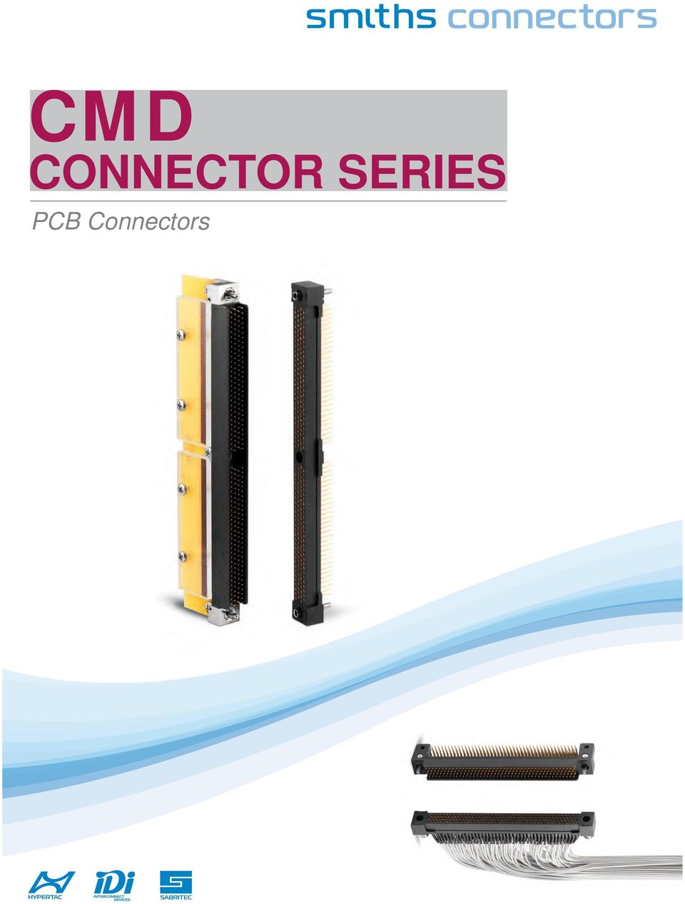
1 MD ONNETO SEIES onnectors
2 HYEOLOID TEHNOLOGY Smiths onnectors offers an extensive range of superior contact technologies suitable for standard and custom solutions. Hypertac (HYEboloid contat) is the original superior performing hyperboloid contact technology designed for use in all applications and in harsh and demanding environments where high reliability and safety are critical. The inherent electrical and mechanical characteristics of the Hypertac hyperboloid contact ensures unrivalled performance in terms of reliability, number of mating cycles, low contact force and minimal contact resistance. The shape of the contact sleeve is formed by hyperbolically arranged contact wires, which align themselves elastically as contact lines around the pin, providing a number of linear contact paths. FEATUE LOW INSETION/EXTATION FOES The angle of the socket wires allows tight control of the pin insertion and extraction forces. The spring wires are smoothly deflected to make line contact with the pin. LONG ONTAT LIFE The smooth and light wiping action minimizes wear on the contact surfaces. ontacts perform up to 100,000 insertion/ extraction cycles with minimal degradation in performance. LOWE ONTAT ESISTANE The design provides a far greater contact area and the wiping action of the wires insures a clean and polished contact surface. Our contact technology has about half the resistance of conventional contact designs. HIGHE UENT ATINGS The design parameters of the contact (e.g., the number, diameter and angle of the wires) may be modified for any requirement. The number of wires can be increased so the contact area is distributed over a larger surface. Thus, the high current carried by each wire because of its intimate line contact, can be multiplied many times. IMMUNITY TO SHOK & VIATION The low mass and resultant low inertia of the wires enable them to follow the most abrupt or extreme excursions of the pin without loss of contact. The contact area extends 360 around the pin and is uniform over its entire length. The 3 dimensional symmetry of the Hypertac contact design guarantees electrical continuity in all circumstances. ENEFIT HIGH DENSITY INTEONNET SYSTEMS Significant reductions in size and weight of sub-system designs. No additional hardware is required to overcome mating and un-mating forces. LOW OST OF OWNESHI The Hypertac contact technology will surpass most product requirements, thus eliminating the burden and cost of having to replace the connector or the entire subsystem. LOW OWE ONSUMTION The lower contact resistance of our technology results in a lower voltage drop across the connector reducing the power consumption and heat generation within the system. MAXIMUM ONTAT EFOMANE The lower contact resistance of the Hypertac contact reduces heat build-up; therefore Hypertac contacts are able to handle far greater current in smaller contact assemblies without the detrimental effects of high temperature. ELIAILITY UNDE HASH ENVIONMENTS Harsh environmental conditions require connectors that will sustain their electrical integrity even under the most demanding conditions such as shock and vibration. The Hypertac contact provides unmatched stability in demanding environments when failure is not an option.

3 table of contents cmd series Scope...2 Applied documents...3 equirements...3 Quality assurance provisions...5 ackaging...5 Notes...5 Selection chart...6 lug connector: 42, 82, 110, 126, 158 and 174 pin contact...8 eceptacle connector: 42, 82, 110, 126, 158 and 174 socket contact...17 lug connector: 220, 236 and 316 pin contact...26 eceptacle connector: 220, 236 and 316 socket contact...35 olarization configuration chart...44 Maximum dimensions of mated connectors...45 The connector halves mating...50 onnectors for measuring and yesy...53 Flex circuit soldering...59 Dimension are in mm and inches 1

4 MD 1. SOE 1.1 Scope This Design covers MD onnectors Family, plug and receptacle style, with 42, 82, 110, 126, 158, 174, 220, 236 and 316 pin or socket contact, conforming to MIL ontact arrangement is offset-grid pattern within dielectric connector body with four rows,.075 in ( mm) center-to-center contact spacing in each row, and.075 in ( mm) row-to-row spacing. ontact size is 0.6 mm nominal pin DIA.olarization feature is incorporated in each connector assembly to assure correct insertion. oding key system provides 36 possible keying combinations. There are available, moreover, suitable dielectric connector body cavities aimed at ground contacts, shielded contacts, co-axial contacts, databus contacts, fiber optic termini, etc. 1.2 ontact terminal types lug connector, pin contacts equipped, contact terminal types available are: a. solder post, thru hole, as dip solder right angle contact terminal for rigid, (daughterboard application, or in line arrangement board-to-board connection); b. solder post, thru hole, as dip solder straight contact terminal for rigid, (in parallel arrangement board-to-board connection); c. solder tail, as surface mount contact terminal for rigid W, when plug connector is assembled with properflex-circuit conforming to MIL , and its surface mount tails are the contact terminals for straddle mount, (daughterboard application, or in line arrangement board-to-board connection) eceptacle connector, socket contact equipped, contact terminal types available are: a. solder post, thru hole, as dip solder straight contact terminal for rigid W, (motherboard application, or in parallel arrangement board-to-board connection); b. solder post, thru hole, as dip solder right angle contact terminal for rigid, (in line arrangementboard-to-board connection); c. wire wrap post, as solderless contact terminal in accordance with MIL-STD-1130, (backplane attachment); d. solder tail, as surface mount contact terminal for rigid, when receptacle connector is assembled with proper flex-circuit conforming to MIL , and its surface mount tails are the contact terminals for straddle mount, (in line arrangement board-to-board connection). 1.3 lug and receptacle connectors for measuring and test devices available are: a. plug and receptacle connector for extender board, (as rigid vehicle for measuring and test devices); b. plug and receptacle connector for cable assembly, (as flexible vehicle for measuring and test devices); c. card edge receptacle test connector and its proper plug connector, (for measuring and test devices). 2

5 MD 2. ALIED DOUMENTS 2.1 Applied documents MD onnectors Family is designed, manufactured, tested and delivered in accordance with the documents listed below. The latest issue of the following documents, documents amendments and notices, in being on 30 June 1994 are used unless otherwise specified in this Design. MIL oatings, electroless nickel requirement for. MIL-I Insulating compound, electrical (for coating printed circuit assemblies). MIL rinted-wiring, flexible and rigid-flex. MIL onnectors, printed circuit subassembly and accessories. MIL-I Insulating compound electrical, embedding, reversion resistant silicone. MIL-STD-1130 onnections, electrical, solderless wrapped. MIL-STD-2118 Flexible and rigid-flex printed-wiring for electronic equipment design requirements for. MS21209 Insert, screw thread, coarse and fine, screw locking, helical coil, cres. 3. EQUIEMENTS 3.1 onnector body is an insulator body of molded one-piece construction onnector body material is iniection molded from glass reinforced polyphenylene sulfide (S) type GST-40F per MIL-M and in accordance with MIL This thermoplastic compound is flame resistant, having flammability rating V-O/5VA, without additives, per UL in contact and contact terminal in contact and dip solder, (right angle and straight), contact terminal are screw machined, and one-piece construction in contact and dip solder, (right angle and straight), contact terminal materials are beryllium-copper alloy per QQ--530, (ASTM 197), with protective finishing of gold plate, over suitable underplate, as specified in MIL in contact and crimp contact terminal are screw machined, one-piece construction in contact and crimp contact terminal materials are copper-alloy per QQ--626, (ASTM 16), with protective finishing of gold plate, over suitable underplate, as specified in MIL in contact and its surface mount tail terminal are two-pieces construction type. These two-parts are assembled in one-piece construction using a suitable tin-lead soldering in contact and its surface mount tail terminal materials. in contact screw machined from copper-alloy per QQ--626, (ASTM 16), with protective finishing of gold plate, over suitable underplate, as specified in MIL The surface mount tail terminal is the part of a proper flex-circuit conforming to MIL with tail finishing of tin-lead (50 70%) composition,.50 to.80 mil (12 to 20 µmm) thick, per MIL in contact is soldered with flex-circuit, as its contact terminal, using solder alloy composition Sn63 conforming to QQ-S

6 MD 3.3 Socket contact and contact terminal Socket contact is HYETA and contact terminal types are: dip solder, (straight and right angle), wire wrappost, surface mount tail, and crimp Socket contact materials HYETA springs are wiredrawn from beryllium-copper alloy per QQ--530, (ASTM 197). Socket contact body is screw machined from copper-alloy per QQ--626, (ASTM 16). rotective finishing is gold plate, over suitable underplate, as specified in MIL Dip solder, (straight and right angle), wire wrappost, and crimp socket contact terminals are screw machined, one-piece construction Dip solder, (straight and right angle), wire wrappost, and crimp socket contact terminal materials are proper copper-alloys in accordance with MIL , with protective finishing of gold plate, over suitable underplate, asspecified in MIL Socket contact surface mount tail terminal is two-pieces construction type. These two-parts are assembled in onepiece construction using a suitable tin-lead soldering Socket contact end and its surface mount tail terminal materials. Socket contact end is screw machined from copper-alloy per QQ--626, (ASTM 16), with finishing of tin-lead (50 70%) composition per MIL over nickel underplate per QQ-N-290. The surface mount tail terminal is the part of a proper flex-circuit conforming to MIL with tail finishing of tin-lead (50 70%) composition,.50 to.80 mil (12 to 20 µmm) thick, per MIL Socket contact end is soldered with flex-circuit, as its contact terminal, using solder alloy composition Sn63 conforming to QQ-S onnector hardware is formed by male guide pins plus female guide sockets (polarized, unpolarized and omnipolarized types), mounting hardware, and joining devices onnector hardware materials Male guide pins are screw machined from stainless steel per ASTM A582, (AISI 303), and passivated per QQ--35. Female guide sockets, (polarized, unpolarized and omnipolarized types), are screw machined from beryllium-copper alloy per QQ--530, (ASTM 196), and nickel plated per QQ-N-290. Mounting hardware is machined from aluminum alloy per QQ-A-250/4 and finished with electroless nickel coating per MIL Joining devices are machined from corrosion-resistant steel per QQ-S-766, (ASTM A666), and passivated per QQ--35.Threaded inserts, self-locking type, are conforming to MS olarization guide set provides 36 possible polarized position combinations; plus unpolarized male guide pins on plug connector, and omnipolarized female guide sockets on receptacle connector for measuring and test devices, (i.e.extender board applications), as shown on page 44 of this catalog. 3.5 Design and construction of MD onnectors Family are in accordance with MIL requirements. 4

7 MD 3.6 MD onnectors Family requirements are: - contact engagement and separation forces: maximum engagement force 100 g (3.53 oz); minimum separation force 14 g (.49 oz); - connector mating and unmating forces: maximum mating force 60 g (2.12 oz) multiplied by number of contacts;minimum unmating force 20 g (.71 oz) multiplied by number of contacts; - contact current rating: the connector may have any combination of current flow and ambient temperature provided the contact or connector temperature does not exceed 125. If mated plug and receptacle connectors are both equipped with dip solder, or wire wrappost, or crimp as contact terminals, the test current is 3.0 A for individually connected contact, and 2.0 A for series wired contacts; if mated plug and receptacle connectors are, one of them or both of them,assembled with flex-circuit as surface mount tail contact terminals, test current is 1.5 A for individually connected contact, and 1.0 A for series wired contacts, in accordance with MIL-STD mated contact resistance: 5.0 mω maximum individual, if pin and socket contacts have dip solder, or wire wrappost,or crimp as contact terminals; the flex-circuit resistance plus the soldering resistance, (namely surface mount tailterminal resistance), is 4.0 mω maximum individual; the total resistance equals the surface mount tail terminal resistanceplus the mated contact resistance; - temperature range: normal operating temperature is between -65 and +125 ; - dielectric withstanding voltage: 750 VMS, 60 Hz at sea level, 250 VMS, 60 Hz at 70,000 feet (21,336 m), when flex-circuit and its surface mount tails are conformally coated of a suitable electrical insulating compound as specified in MIL-I-46058; - insulation resistance is 5000 MΩ at 500 VD; - contact life: 30,000 insertion and withdrawal cycles, with minimum wear; - vibration: when tested in accordance with MIL , and MIL-STD-1344 method 2005, Hz, 15 G peak,4 h per axis, 100 ma, there are no interruption in continuity greater than 2 ns of the test circuit which incorporates mated contacts; - shock: when tested in accordance with MIL , and MIL-STD-1344 method 2004, 6 ms, 100 G sawtooth, six shocks, 100 ma, there are no interruption in continuity greater than 2 ns of the test circuit which incorporates mated contacts; - solderability: in accordance with MIL-STD-202 method 208 at an uniform temperature of 245 for 5 s; - resistance to soldering heat: in accordance with MIL-STD-202 method 210 condition, 260 for 10 s; - capacitance: contact to contact maximum 2.0 pf; - calculated inductance: maximum 15 nh 4. QUALITY ASSUANE OVISIONS MD onnectors Family is inspected using data values of Section 3 of this Design, and examinations and test methods in accordance with MIL AKAGING 5.1 ackaging requirements are in accordance with ONNEI s ackaging rocedures, and then packaging is adeguate to provide protection against any damage, breakage, or loss during shipment from the supply source to the ultimate using activity. 6. notes 6.1 Intended use MD onnectors Family is designed for printed wiring board-to-printed wiring board, or printed wiring board-to-cable interconnection, of high density electronic packaging equipment subassemblies with low-power requirements. 5

8 MD SELETION HAT ODY ONNETO DIMENSIONS H W D onnector figure (mating face) W max H max D max (1) (2) (1) (2) (1) (2) (1) (2) (1) (2) (1) (2) (1) (2) (1) (2) (1) (2) 8.00 (1) Applicable to plug connector body equipped with dip solder, straight thru, contact terminal. (2) Applicable to plug connector body equipped with all the other contact terminal styles. 6
 Applicable to plug connector body equipped with all the other contact terminal styles. 6")
9 MD ontact terminal types available are: ontact onnector style (Straight thru) Dip solder (ight angle) Surface mount tail Wire wrap post See pages lug connector pin contacts equipped heck Firm No 10 to eceptacle connector socket contacts equipped heck Firm 18 to 27 lug connector pin contacts equipped heck Firm No 10 to eceptacle connector socket contacts equipped heck Firm 18 to 27 lug connector pin contacts equipped No 10 to eceptacle connector socket contacts equipped 18 to 27 lug connector pin contacts equipped heck Firm No 10 to eceptacle connector socket contacts equipped heck Firm 18 to 27 lug connector pin contacts equipped No 10 to eceptacle connector socket contacts equipped 18 to 27 lug connector pin contacts equipped No 10 to eceptacle connector socket contacts equipped 18 to 27 lug connector pin contacts equipped heck Firm heck Firm No 28 to eceptacle connector socket contacts equipped heck Firm 37 to 45 lug connector pin contacts equipped heck Firm No 28 to eceptacle connector socket contacts equipped 37 to 45 lug connector pin contacts equipped heck Firm No 28 to eceptacle connector socket contacts equipped 37 to 45 7

10 MD LUG ONNETO: 42, 82, 110, 126, 158 AND 174 IN ONTAT OSITIONS LUG ONNETO: 42, 82, 110, 126, 158 and 174 IN ONTAT OSITIONS,.075 INH SAING ( mm), DI SOLDE (IGHT ANGLE) TEMINAL STYLE A max 4.00 Last contact position A Ø 2.70 thru places max 5.08 A ontact position 1 ontact position MD***M****H ****** D-shaped guide pins max 6.86 L2.76 L3.55 L4.37 L 0.70 ±0.10 M1.6 threaded screw Ø 0.48 See detail A M1.6 threaded nut 3.90 x DETAIL A SETION - SETION A-A Figure 2 MOUNTING ATTEN, DAUGHTEOAD ALIATION, (EOMMENDED HOLE ONFIGUATION) OMONENT SIDE Ø 0.70 min 0.05 Ø 5.08 Last hole position Ø (2 holes) 0.10 Ø M x N N max Figure 3 8
 OMONENT SIDE Ø 0.70 min 0.05 Ø 5.08 Last hole position Ø 2.70 +0.10 0.")
11 MD LUG ONNETO: 42, 82, 110, 126, 158 and 174 IN ONTAT OSITIONS table I table II ontact Dimensions in width A Weight* in grams (with g9.81 m/s 2 ) ontact from to * According to contacts terminal length, and with D-shaped guide pins installed NOTES 1. Dimensions for user installation purpose only. 2. Dimensions are in millimeters. 3. Dimensions in width of these connectors are specified in the table I of this page. 4. Materials, finishes and connectors requirements are described into this catalog. Hot solder dipping,as dip solder terminal end finishing, is available at ustomer request, (please consult the Factory). 5. These plug connectors are conforming to MIL These plug connectors mate MD***EF****H receptacle connectors, (see pages 17 to 24), when both of them, (plug and receptacle), are equipped with the same contact number, appropriate hardware, and identical polarizing combination. 7. Weights of these connectors are specified in the table II of this page. 8. onnectors for measuring and test devices, (i.e. extender board applications), are indicated on pages 53 to 58. 9

12 MD how to order connector family connector size contact contact contact contact connector style plug connector contact style M pin contact contact terminal style Dip solder, right angle, with: A.109 inch (2.76 mm) long dip.140 inch (3.55 mm) long dip hardware code Y D-shaped guide pins hardware polarization 0 0 universal coupling guide pins (for test type connectors) 110 contact 174 contact.172 inch (4.37 mm) long dip When D-shaped guide pins are installed in the 01 polarized position, (see polarization configuration chart on page 44), WITHOUT Loctite 242 applied. 0 1 to 3 6 When D-shaped guide pins are installed in the proper polarized position and Loctite 242 is applied t o TO the threads, (see polarization configuration chart on page 44) M D M H When universal coupling guide pins, (for test type connectors), are installed. When D-shaped guide pins or universal coupling guide pins (for test type connectors), are shipped loose in a plastic bag. contact finishing H ontacts with plating and underplating conforming to MIL
 long dip When D-shaped guide pins are installed in the 01 polarized position, (see polarization configuration chart on page 44), WITHOUT Loctite 242 applied.")
13 MD LUG ONNETO: 42, 82, 110, 126, 158 and 174 IN ONTAT OSITIONS LUG ONNETO: 42, 82, 110, 126, 158 and 174 IN ONTAT OSITIONS,.075 INH SAING ( mm), DI SOLDE (STAIGHT) TEMINAL STYLE A max 4.00 Last contact position max 5.08 ontact position 1 ontact position min M2.50 threaded screw MD***M****H ****** D-shaped guide pins max 7.00 L Ø 0.48 L2.76 L5.94 L4.37 L3.55 Figure 4 MOUNTING ATTEN, IN AALLEL AANGEMENT OAD-TO-OAD ONNETION, (EOMMENDED HOLE ONFIGUATION) OMONENT SIDE Ø 0.70 min 0.05 Ø 5.08 LAST HOLE OSITION Ø (2 holes) 0.10 Ø M x N N Figure 5 11
 OMONENT SIDE Ø 0.70 min 0.05 Ø 5.")
14 MD LUG ONNETO: 42, 82, 110, 126, 158 and 174 ONTAT OSITIONS table I table II ontact Dimensions in width A Weight* in grams (with g9.81 m/s 2 ) ontact from to * According to contacts terminal length, and with D-shaped guide pins installed NOTES 1. Dimensions for User installation purpose only. 2. Dimensions are in millimeters. 3. Dimensions in width of these connectors are specified in the table I of this page. 4. Materials, finishes and connectors requirements are described into this catalog. Hot solder dipping,as dip solder terminal end finishing, is available at ustomer request, (please consult the Factory). 5. These plug connectors are conforming to MIL These plug connectors mate MD***EF****H receptacle connectors, (see pages 17 to 24), when both of them, (plug and receptacle), are equipped with the same contact number, appropriate hardware, and identical polarizing combination. 7. Weights of these connectors are specified in the table II of this page. 8. onnectors for measuring and test devices, (i.e. extender board applications), are indicated on pages 53 to

15 MD how to order connector family connector size contact contact contact contact connector style plug connector contact style M pin contact contact terminal style Dip solder, straight thru, with: D.109 inch (2.76 mm) long dip E G.172 inch (4.37 mm) long dip L hardware code Y D-shaped guide pins hardware polarization 0 1 to M D M H.140 inch (3.55 mm) long dip.234 inch (5.94 mm) long dip 110 contact 174 contact universal coupling guide pins (for test type connectors) When D-shaped guide pins are installed in the proper polarized position (see polarization configuration chart on page 44). When universal coupling guide pins, (for test type connectors), are installed. When D-shaped guide pins or universal coupling guide pins (for test type connectors), are shipped loose i n IN a plastic bag. contact finishing H ontacts with plating and underplating conforming to MIL
 long dip 110 contact 174 contact universal coupling guide pins (for test type connectors) When D-shaped guide pins are installed in the proper polarized position (see polarization")
16 MD LUG ONNETO: 42, 82, 110, 126, 158 AND 174 IN ONTAT OSITIONS LUG ONNETO: 42, 82, 110, 126, 158 AND 174 ONTAT OSITIONS,.075 INH SAING ( MM), OAD AKAGE THIKNESS FOM 1.00 TO 4.20 MM 4.00 Last contact position A max M2.5 2 places S0.75 mm S1.10 mm S1.85 mm S1.60 mm S max 5.08 ontact position 1 ontact position MD***M****H D-shaped guide pins ****** max Figure 6 ONTAT ATTEN NUMEING N SIDE OOSITE MATING FAE 2 1 N+1 Last terminal position Figure 7 TALE I TALE II ontact Dimensions in width A Weight* in grams (with g9.81 m/s 2 ) ontact from to * According to variations of soldering and insulating compound weight, and with D-shaped guide pins installed 14
 ontact from to 42 8.0 9.0 82 11.5 12.5 110 13.5 14.")
17 MD LUG ONNETO: 42, 82, 110, 126, 158 AND 174 IN ONTAT OSITIONS MOUNTING ATTEN, DAUGHTEOAD ALIATION max 0.55 min View side A 4.10 max min MTG hole 2 places Edge of board onnector dimensions min side side A View side Figure 8 NOTES 1. Dimensions for User installation purpose only. 2. Dimensions are in millimeters. 3. Dimensions in width of these connectors are specified in the table I of the previous page. 4. Materials, finishes and connectors requirements are described into this catalog. 5. These plug connectors are conforming to MIL , and their flex circuits, as surfacemount tail terminals, are in accordance with MIL These plug connectors mate MD***EF****H receptacle connectors, (see pages 17 to 24), when both of them, (plug and receptacle), are equipped with the same contact number, appropriate hardware, and identical polarizing combination. 7. Weights of these connectors are specified in the table II of the previous page. 8. onnectors for measuring and test devices, (i.e. extender board applications), are indicated on pages 53 to

18 MD how to order connector family connector size check firm 42 contact check firm 82 contact check firm 126 contact contact connector style plug connector contact style M pin contact 110 contact 174 contact contact terminal style Flex circuit for straddle mount, with board package thickness: N T from.039 to 0.79 inch (from 1.00 to 2.00 mm) from.106 to.146 INH (from 2.70 to 3.70 mm) V hardware code Y D-shaped guide pins hardware polarization 0 0 from.067 to.106 INH (from 1.70 to 2.70 mm) from.126 to.165 INH (from 3.20 to 4.20 mm) universal coupling guide pins (for test type connectors) When D-shaped guide pins are installed in the 01 polarized position, (see polarization configuration chart on page 44), WITHOUT Loctite 242 applied. 0 1 to 3 6 When D-shaped guide pins are installed in the proper polarized position and Loctite 242 is applied t o TO the threads, (see polarization configuration chart on page 44) M D M H When universal coupling guide pins, (for test type connectors), are installed. When D-shaped guide pins or universal coupling guide pins (for test type connectors), are shipped loose in a plastic bag. contact finishing H ontacts with plating and underplating conforming to MIL
 universal coupling guide pins (for test type connectors) When D-shaped guide pins are installed in the 01 polarized position, (see polarization configuration chart on page 44), WITHOUT Loctite")
19 MD receptacle ONNETO: 42, 82, 110, 126, 158 and 174 socket ONTAT OSITIONS EETALE ONNETO: 42, 82, 110, 126, 158 and 174 SOKET ONTAT OSITIONS,.075 INH SAING ( mm), DI SOLDE (STAIGHT), AND WIE WA OST TEMINAL STYLE A 8.00 max A max D-shaped guide sockets 2.10 A 7.00 MD***EF****H M2.50 threaded screw ****** 0.60 min L Ø 0.48 L2.76 L3.55 L4.37 L SQ max 4.00 ontact position 1 ontact position VIEW A-A Dip solder, straight terminal equipped. VIEW A-A ut wire wrap post terminal equipped. Last contact position Figure 9 MOUNTING ATTEN, MOTHEOAD ALIATION, (EOMMENDED W HOLE ONFIGUATION) x OMONENT SIDE N 2 1 N+1 Last hole position Ø 0.70 min Ø Ø 0.00 (2 holes) 0.10 Ø M Figure 10 EOMMENDED ANEL UT-OUT D min 9.50 min Ø (2 holes) 0.20 Ø M Figure 11 17
 x3 5.715 5.08 OMONENT SIDE N 2 1 N+1 Last hole position Ø 0.70 min Ø 2.70 +0.10 0.05 Ø 0.")
20 MD receptacle ONNETO: 42, 82, 110, 126, 158 and 174 socket ONTAT OSITIONS table I table II ontact A Dimensions in width D Weight* in grams (with g9.81 m/s 2 ) ontact from to * According to contacts terminal length (straight type), and with D-shaped guide socket installed NOTES 1. Dimensions for user installation purpose only. 2. Dimensions are in millimeters. 3. Dimensions in width of these connectors are specified in the table I of this page. 4. Materials, finishes and connectors requirements are described into this catalog. Hot solder dipping, as dip solder terminal end finishing, is available at ustomer request, (please consult the Factory). 5. These receptacle connectors are conforming to MIL These receptacle connectors mate MD***M****H plug connectors, (see pages 8 to 16), when both of them, (receptacle and plug), are equipped with the same contact number, appropriate hardware, and identical polarizing combination. 7. Weights of these connectors are specified in the table II of this page. 8. onnectors for measuring and test devices, (i.e. extender board applications), are indicated on pages 53 to

21 MD how to order M D E F H connector family connector size contact contact contact contact connector style E receptacle connector contact style F socket contact contact terminal style Dip solder, straight thru, with: D.109 inch (2.76 mm) long dip E G.172 inch (4.37 mm) long dip L Wire wrap with: Y.625 inch ( mm) long post hardware code Y D-shaped guide sockets hardware polarization 0 1 to inch (3.55 mm) long dip.234 inch (5.94 mm) long dip 110 contact 174 contact universal coupling guide sockets (for test type connectors) When D-shaped guide sockets are installed in the proper polarized position (see polarization configuration chart on page 44). When universal coupling guide sockets, (for test type connectors), are installed. 3 8 When D-shaped guide sockets or universal coupling guide sockets (for test type connectors), are shipped loose in a plastic bag. 8 contact finishing H ontacts with plating and underplating conforming to MIL
22 MD EETALE ONNETO: 42, 82, 110, 126, 158 AND 174 SOKET ONTAT OSITIONS EETALE ONNETO: 42, 82, 110, 126, 158 AND 174 SOKET ONTAT OSITIONS,.075 INH SAING ( MM), OAD AKAGE THIKNESS FOM 1.00 TO 4.20 MM A max D-shaped guide sockets 2.10 MD***EF****H xxxx max M2.5 2 places S S0.75 mm S1.10 mm S1.60 mm S1.85 mm max 4.00 ontact position 1 ontact position Last contact position Figure 12 ONTAT ATTEN NUMEING SIDE OOSITE MATING FAE Last terminal position N+1 N 2 1 Figure 13 TALE I TALE II ontact Dimensions in width A Weight* in grams (with g9.81 m/s 2 ) ontact from to * According to variations of soldering and insulating compound weight, and with D-shaped guide sockets installed 20
23 MD EETALE ONNETO: 42, 82, 110, 126, 158 AND 174 SOKET ONTAT OSITIONS MOUNTING ATTEN, DAUGHTEOAD ALIATION max 0.55 mim View side A 4.10 max min MTG hole 2 places Edge of board onnector dimensions min side side A View side Figure 14 NOTES 1. Dimensions for user installation purpose only. 2. Dimensions are in millimeters. 3. Dimensions in width of these connectors are specified in the table I of the previous page. 4. Materials, finishes and connectors requirements are described into this catalog. 5. These receptacle connectors are conforming to MIL , and their flex-circuits, as surface mount tail terminals, are in accordance with MIL These receptacle connectors mate MD***M****H plug connectors, (see pages 8 to 16), when both of them, (receptacle and plug), are equipped with the same contact number, appropriate hardware, and identical polarizing combination. 7. Weights of these connectors are specified in the table II of the previous page. 8. onnectors for measuring and test devices, (i.e. extender board applications), are indicated on pages 53 to
24 MD how to order M D E F H connector family connector size check firm 42 contact check firm 82 contact contact check firm 126 contact contact connector style E receptacle connector contact style F socket contact 174 contact contact terminal style Flex circuit for straddle mount, with board package thickness: N from.039 to.079 INH (from 1.00 to 2.00 mm) from.067 to.106 INH (from 1.70 to 2.70 mm) T from.106 to.146 INH (from 2.70 to 3.70 mm) V from.126 to.165 INH (from 3.20 to 4.20 mm) 6 7 hardware code Y D-shaped guide SOKETS hardware polarization 0 0 universal coupling guide SOKETS (for test type connectors) When D-shaped guide sockets are installed in the 01 polarized position, (see polarization configurations chart on page 44), without Loctite 242 applied. 0 1 to When D-shaped guide sockets are installed in the proper polarized position and Loctite 242 is applied to the threads, (see polarization configuration chart on page 44). When universal coupling guide sockets, (for test type connectors), are installed. 3 8 When D-shaped guide sockets or universal coupling guide sockets (for test type connectors), are shipped loose in a plastic bag. 8 contact finishing H ontacts with plating and underplating conforming to MIL
25 MD receptacle ONNETO: 42, 82, 110, 126, 158 and 174 socket ONTAT OSITIONS EETALE ONNETO: 42, 82, 110, 126, 158 and 174 SOKET ONTAT OSITIONS,.075 INH SAING ( mm), DI SOLDE (IGHT ANGLE) TEMINAL STYLE A max 8.00 max D-shaped guide sockets 2.10 MD***EF****H ****** 8.00 x max ontact position 1 ontact position M2.50 threaded thru hole L2.76 L3.55 L4.37 L Ø 0.48 Last contact position Figure 15 MOUNTING ATTEN, EXTENDE OAD AND IN LINE OAD-TO-OAD ALIATIONS, (EOMMENDED HOLE ONFIGUATION) OMONENT SIDE x max Last hole position 5.08 N 2 1 N+1 Ø 0.70 min 0.05 Ø Ø (2 holes) Ø 0.10 M Figure 16 23
26 MD receptacle ONNETO: 42, 82, 110, 126, 158 and 174 socket ONTAT OSITIONS table I table II ontact A Dimensions in width D Weight* in grams (with g9.81 m/s 2 ) ontact from to * According to contacts terminal length and with D-shaped guide sockets installed NOTES 1. Dimensions for user installation purpose only. 2. Dimensions are in millimeters. 3. Dimensions in width of these connectors are specified in the table I of this page. 4. Materials, finishes and connectors requirements are described into this catalog. Hot solder dipping, as dip solder terminal end finishing, is available at ustomer request, (please consult the Factory). 5. These receptacle connectors are conforming to MIL These receptacle connectors mate MD***M****H plug connectors, (see pages 8 to 16), when both of them, (receptacle and plug), are equipped with the same contact number, appropriate hardware, and identical polarizing combination. 7. Weights of these connectors are specified in the table II of this page. 8. onnectors for measuring and test devices, (i.e. extender board applications), are indicated on pages 53 to
27 MD how to order M D E F H connector family connector size contact contact contact contact contact contact connector style E receptacle connector contact style F socket contact contact terminal style Dip solder, right angle, with: A.109 inch (2.76 mm) long dip.140 inch (3.55 mm) long dip.172 inch (4.37 mm) long dip hardware code Y D-shaped guide SOKETS hardware polarization 0 0 universal coupling guide SOKETS (for test type connectors) When D-shaped guide sockets are installed in the 01 polarized position, (see polarization configurations chart on page 44), without Loctite 242 applied. 0 1 to When D-shaped guide sockets are installed in the proper polarized position and Loctite 242 is applied to the threads, (see polarization configuration chart on page 44). When universal coupling guide sockets, (for test type connectors), are installed. 3 8 When D-shaped guide sockets or universal coupling guide sockets, (for test type connectors), are shipped loose in a plastic bag. 8 contact finishing H ontacts with plating and underplating conforming to MIL
28 MD plug ONNETO: 220, 236 AND 316 pin ONTAT OSITIONS LUG ONNETO: 220, 236 AND 316 IN ONTAT OSITIONS,.075 INH SAING ( mm), DI SOLDE (IGHT ANGLE) TEMINAL STYLE A max 4.00 Last contact position A max A ontact position 1 ontact position 2 Ø 2.70 thru 3 places MD***M***** ****** max 5.08 D-shaped guide pins L2.76 L3.55 L4.37 L Ø 0.48 See detail A 0.70 ±0.10 M1.6 threaded screw x M1.6 threaded nut Section A-A Detail A Section - Figure 17 MOUNTING ATTEN, DAUGHTEOAD ALIATION, (EOMMENDED HOLE ONFIGUATION) x Last hole position 5.08 OMONENT SIDE 7.62 N+1 N 2 1 Ø 0.70 min 7.15 Ø max 0.05 Ø (3 holes) 0.10 Ø M Figure 18 26
29 MD plug ONNETO: 220, 236 AND 316 pin ONTAT OSITIONS table I table II ontact Dimensions in width A Weight* in grams (with g9.81 m/s 2 ) ontact from to * According to contacts terminal length and with D-shaped guide pins installed NOTES 1. Dimensions for user installation purpose only. 2. Dimensions are in millimeters. 3. Dimensions in width of these connectors are specified in the table I of this page. 4. Materials, finishes and connectors requirements are described into this catalog. Hot solder dipping, as dip solder terminal end finishing, is available at ustomer request, (please consult the Factory). 5. These plug connectors are conforming to MIL These plug connectors mate MD***EF****H receptacle connectors, (see pages 35 to 43), when both of them, (plug and receptacle), are equipped with the same contact number, appropriate hardware, and identical polarizing combination. 7. Weights of these connectors are specified in the table II of this page. 8. onnectors for measuring and test devices, (i.e. extender board applications), are indicated on pages 53 to
30 MD how to order M D M H connector family connector size contact contact OSITIONS connector style plug connector contact style M pin contact contact terminal style Dip solder, right angle, with: A.109 inch (2.76 mm) long dip.140 inch (3.55 mm) long dip hardware code Y D-shaped guide pins hardware polarization 0 0 universal coupling guide pins (for test type connectors) 316 contact.172 inch (4.37 mm) long dip When D-shaped guide pins are installed in the 01 polarized position, (see polarization configurations chart on page 44), without Loctite 242 applied. 0 1 to When D-shaped guide pins are installed in the proper polarized position and Loctite 242 is applied to the threads, (see polarization configuration chart on page 44). When universal coupling guide pins, (for test type connectors), are installed. When D-shaped guide pins or universal coupling guide pins, (for test type connectors), are shipped loose in a plastic bag. contact finishing H ontacts with plating and underplating conforming to MIL
31 MD plug ONNETO: 220, 236 AND 316 pin ONTAT OSITIONS LUG ONNETO: 220, 236 AND 316 IN ONTAT OSITIONS,.075 INH SAING ( mm), DI SOLDE (STAIGHT) TEMINAL STYLe A max 4.00 ast contact position max ontact position 1 ontact position min MD***M***** M2.50 threaded screw ****** 7.00 L Ø 0.48 L2.76 L5.94 L4.37 L D-shaped guide pins max Figure 19 MOUNTING ATTEN, IN AALLEL AANGEMENT OAD-TO-OAD ONNETION, (EOMMENDED HOLE ONFIGUATION) OMONENT SIDE Ø 0.70 min 0.05 Ø x Last hole position Ø (3 holes) N+1 N Ø M Figure 20 29
32 MD plug ONNETO: 220, 236 AND 316 pin ONTAT OSITIONS table I table II ontact Dimensions in width A Weight* in grams (with g9.81 m/s 2 ) ontact from to * According to contacts terminal length and with D-shaped guide pins installed NOTES 1. Dimensions for User installation purpose only. 2. Dimensions are in millimeters. 3. Dimensions in width of these connectors are specified in the table I of this page. 4. Materials, finishes and connectors requirements are described into this catalog. Hot solder dipping, as dip solder terminal end finishing, is available at ustomer request, (please consult the Factory). 5. These plug connectors are conforming to MIL These plug connectors mate MD***EF****H receptacle connectors, (see pages 35 to 43), when both of them, (plug and receptacle), are equipped with the same contact number, appropriate hardware, and identical polarizing combination. 7. Weights of these connectors are specified in the table II of this page. 8. onnectors for measuring and test devices, (i.e. extender board applications), are indicated on pages 53 to
33 MD how to order M D M H connector family connector size check firm 220 contact check firm 316 contact check firm 236 contact connector style plug connector contact style M pin contact contact terminal style Dip solder, straight thru, with: D.109 inch (2.76 mm) long dip E G.172 inch (4.37 mm) long dip L hardware code Y D-shaped guide pins hardware polarization 0 1 to inch (3.55 mm) long dip.234 inch (5.94 mm) long dip universal coupling guide pins (for test type connectors) When D-shaped guide pins are installed in the proper polarized position, (see polarization configuration chart on page 44). When universal coupling guide pins, (for test type connectors), are installed. When D-shaped guide pins or universal coupling guide pins, (for test type connectors), are shipped loose in a plastic bag. contact finishing H ontacts with plating and underplating conforming to MIL
34 MD LUG ONNETO: 220, 236 AND 316 IN ONTAT OSITIONS LUG ONNETO: 220, 236 AND 316 IN ONTAT OSITIONS,.075 INH SAING ( MM), OAD AKAGE THIKNESS FOM 1.00 TO 4.20 MM A max 4.00 Last contact position max ontact position 1 ontact position 2 M2.5 3 places MD***M***** ****** max S S0.75 mm S1.10 mm S1.60 mm S1.85 mm 5.08 D-shaped guide pins Figure 21 ONTAT ATTEN NUMEING SIDE OOSITE MATING FAE N+1 N 2 1 Last terminal position Figure 22 TALE I TALE II ontact Dimensions in width A ontact Weight* in grams (with g9.81 m/s 2 ) from to * According to variations of soldering and insulating compound weight, and with D-shaped guide pins installed 32
35 MD LUG ONNETO: 220, 236 AND 316 IN ONTAT OSITIONS MOUNTING ATTEN, DAUGHTEOAD ALIATION max 0.55 min View side A 4.10 max min MTG hole 2 places Edge of board onnector dimensions min side side A View side Figure 23 NOTES 1. Dimensions for user installation purpose only. 2. Dimensions are in millimeters. 3. Dimensions in width of these connectors are specified in the table I of the previous page. 4. Materials, finishes and connectors requirements are described into this catalog. 5. These plug connectors are conforming to MIL , and their flex circuits, as surface mount tail terminals, are in accordance with MIL These plug connectors mate MD***EF****H receptacle connectors, (see pages 35 to 43), when both of them, (plug and receptacle), are equipped with the same contact number, appropriate hardware, and identical polarizing combination. 7. Weights of these connectors are specified in the table II of the previous page. 8. onnectors for measuring and test devices, (i.e. extender board applications), are indicated on pages 53 to
36 MD how to order M D M H connector family connector size check firm 220 contact contact contact connector style plug connector contact style M pin contact contact terminal style Flex circuiy straddle mount, with board package thickness: N T from.039 to.079 INH (from 1.00 to 2.00 mm) from.106 to.146 INH (from 2.70 to 3.70 mm) V hardware code Y D-shaped guide pins hardware polarization 0 0 from.067 to.106 INH (from 1.70 to 2.70 mm) from.126 to.165 INH (from 3.20 to 4.20 mm) universal coupling guide pins (for test type connectors) When D-shaped guide pins are installed in the 01 polarized position, (see polarization configurations chart on page 44), without Loctite 242 applied. 0 1 to When D-shaped guide pins are installed in the proper polarized position and Loctite 242 is applied to the threads, (see polarization configuration chart on page 44). When universal coupling guide pins, (for test type connectors), are installed. When D-shaped guide pins or universal coupling guide pins, (for test type connectors), are shipped loose in a plastic bag. contact finishing H ontacts with plating and underplating conforming to MIL
37 MD receptacle ONNETO: 220, 236 AND 316 socket ONTAT OSITIONS EETALE ONNETO: 220, 236 AND 316 SOKET ONTAT OSITIONS,.075 INH SAING ( mm), DI SOLDE (STAIGHT) AND WIE WA OST TEMINAL STYLE A 8.00 max A max D-shaped guide sockets 2.10 L2.76 L5.94 L4.37 L3.55 MD***EF*****H ****** L A 7.00 M2.50 threaded screw 0.60 min Ø SQ max 4.00 ontact position 1 ontact position VIEW A-A Dip solder, straight terminal equipped. VIEW A-A ut wire wrap post terminal equipped. Last contact position 2.60 Thru 4.50; 3.00 Deep Figure 24 MOUNTING ATTEN, MOTHEOAD ALIATION, (EOMMENDED W HOLE ONFIGUATION) OMONENT SIDE 7.62 Ø 0.70 min Ø 0.05 x Last hole position N+1 N 2 1 Ø (3 holes) 0.10 Ø M Figure 25 EOMMENDED ANEL UT-OUT 9.50 min 4.20 ±0.10 D min D min Ø 2.70 (3 holes) Ø M Figure 26 35
38 MD receptacle ONNETO: 220, 236 AND 316 socket ONTAT OSITIONS table I table II ontact Dimensions in width A D Weight* in grams (with g9.81 m/s 2 ) ontact from to * According to contacts terminal length (straight type), and with D-shaped guide sockets installed NOTES 1. Dimensions for user installation purpose only. 2. Dimensions are in millimeters. 3. Dimensions in width of these connectors are specified in the table I of this page. 4. Materials, finishes and connectors requirements are described into this catalog. Hot solder dipping, as dip solder terminal end finishing, is available at ustomer request, (please consult the Factory). 5. These receptacle connectors are conforming to MIL These receptacle connectors mate MD***M****H plug connectors, (see pages 26 to 34), when both of them, (receptacle and plug), are equipped with the same contact number, appropriate hardware, and identical polarizing combination. 7. Weights of these connectors are specified in the table II of this page. 8. onnectors for measuring and test devices, (i.e. extender board applications), are indicated on pages 53 to
39 MD how to order M D E F H connector family connector size contact contact OSITIONS contact connector style E receptacle connector contact style F socket contact contact terminal style Dip solder, straight thru, with: D.109 inch (2.76 mm) long dip E G.172 inch (4.37 mm) long dip L Wire wrap with: Y.625 inch ( mm) long post hardware code Y D-shaped guide socket hardware polarization 0 1 to inch (3.55 mm) long dip.234 inch (5.94 mm) long dip universal coupling guide socket (for test type connectors) When D-shaped guide sockets are installed in the proper polarized position (see polarization configuration chart on page 44). When universal coupling guide sockets, (for test type connectors), are installed. 3 8 When D-shaped guide sockets or universal coupling guide sockets (for test type connectors), are shipped loose in a plastic bag. 8 contact finishing H ontacts with plating and underplating conforming to MIL
40 MD EETALE ONNETO: 220, 236 AND 316 SOKET ONTAT OSITIONS EETALE ONNETO: 220, 236 AND 316 SOKET ONTAT OSITIONS,.075 INH SAING ( MM), OAD AKAGE THIKNESS FOM 1.00 TO 4.20 MM A max D-shaped guide sockets max MD***M***** M2.5 3 places ****** S S0.75 mm S1.10 mm S1.85 mm S1.60 mm max ontact position 1 ontact position Last contact position Figure 27 ONTAT ATTEN NUMEING Last terminal position SIDE OOSITE MATING FAE 2 1 N+1 N Figure 28 ontact TALE I Dimensions in width A TALE II Weight* in grams (with g9.81 m/s 2 ) ontact from to * According to variations of soldering and insulating compound weight, and with D-shaped guide sockets installed 38
41 MD EETALE ONNETO: 220, 236 AND 316 SOKET ONTAT OSITIONS MOUNTING ATTEN, DAUGHTEOAD ALIATION max 0.55 min View side A 4.10 max min MTG hole 3 places onnector dimensions Edge of board min side side A View side Figure 29 NOTES 1. Dimensions for user installation purpose only. 2. Dimensions are in millimeters. 3. Dimensions in width of these connectors are specified in the table I of the previous page. 4. Materials, finishes and connectors requirements are described into this catalog. 5. These receptacle connectors are conforming to MIL , and their flex-circuits, as surface mount tail terminals, are in accordance with MIL These receptacle connectors mate MD***M****H plug connectors, (see pages 26 to 34), when both of them, (receptacle and plug), are equipped with the same contact number, appropriate hardware, and identical polarizing combination. 7. Weights of these connectors are specified in the table II of the previous page. 8. onnectors for measuring and test devices, (i.e. extender board applications), are indicated on pages 53 to
CMD Series. 4 Contact Row High Density Signal Connectors. Technical Characteristics
 MD Series 4 ontact Row High Density Signal onnectors Offset-grid layout, four rows within dielectric connector body, mm center-to-center spacing in each row and row-to-row spacing. 0.6 mm nominal pin DI
Universal MATE-N-LOK Connectors
 Product Facts Pins and sockets can be intermixed in the same housing Positive polarization Rear cavity identification completely enclosed in housings Positive locking housings Insulation capability to.00
Directory chapter 04
 M Directory chapter 04 D-Sub Mixed subminiature D connectors New Page D-Sub mixed connector system general information................... 04.02 Contact arrangements............................................
SOURIAU s discrete wire sealing
 SOURIAU s discrete wire sealing Description Using proven grommet technology from SOURIAU s extensive knowledge of harsh environments, the UTO & UTS connectors with grommet garantie a discrete wire sealing
SMA Interface Mating Dimensions (Per MIL-STD-348)
") SMA Series SMA 6 SMA Interface Mating Dimensions (Per MIL-STD-348) SMA Interface Dimensions MALE Inches/Millimeters 3 Minimum Nominal Maximum LTR in. mm in. mm in. mm A.250 6.35.263 6.68.. B.1790 4.55.1808
SMA Series SMA 6 SMA Interface Mating Dimensions (Per MIL-STD-348) SMA Interface Dimensions MALE Inches/Millimeters 3 Minimum Nominal Maximum LTR in. mm in. mm in. mm A.250 6.35.263 6.68.. B.1790 4.55.1808
UTS discrete wire sealing
 Technical characteristics Mechanical Durability: 250 matings & unmatings Vibration resistance: Sinusoidal vibrations per CEI 605-4 - from 10 to 2000 Hz Thermal shock: 5 cycles 30 min. from -40 C to 105
Directory chapter 02 - DIN Power (to 6 A) Types D, E, F, FM, 2F, F9, interface connectors I/U 02. 01. Technical characteristics types D and E... 02.
 Types D, E, F, FM, 2F, F9, interface connectors I/U 02. 01. Technical characteristics types D and E... 02.") Directory chapter 02 - () Types D, E, F, FM, 2F, F9, interface connectors I/U Page Technical characteristics types D and E.............................. 02.10 Type D connectors.................... 02.11
Directory chapter 02 - () Types D, E, F, FM, 2F, F9, interface connectors I/U Page Technical characteristics types D and E.............................. 02.10 Type D connectors.................... 02.11
08. SEK IDC CONNECTORS
 . IDC CONNECTORS connectors for flat cables enable simple and, cost-optimized device configuration. connectors are preferably used for connection within the device. HARTING offers a broad range of these
A Division Of AVX Corporation. DIN Connectors
 A Division Of AVX Corporation DIN Connectors Index by DIN Style Introduction & Applications 4 Press-Fit 7 Design Aids 8 Approvals 8 Technical Specifications 11 Plating 12 Military Cross Reference 12 STYLE
SMS - Qikmate. Performance characteristics
 - Qikmate Qikmate panel and cable connectors Description The versatile Qikmate panel and cable connectors are a highly cost-effective system approach to solving the constant demand for more cost effective
.093 [2.36] Commercial Pin and Socket Connectors
![.093 [2.36] Commercial Pin and Socket Connectors](/thumbs/40/21560042.jpg ".093 [2.36] Commercial Pin and Socket Connectors") Product Facts Polarized Cavity identification Low contact-mating force Dual locking lances Detent and positive locking Contacts available in brass and phosphor bronze with tin and gold plating Panel mounting
Product Facts Polarized Cavity identification Low contact-mating force Dual locking lances Detent and positive locking Contacts available in brass and phosphor bronze with tin and gold plating Panel mounting
AmphenolR. Now you're connected!
 Table of Contents CoolPower Overview... Page 3 CoolPower Slim Drawer - DW Series... Page 4 CoolPower D-Sub - LCC17 Series... Page 7 Amphenol Power Solutions... Page 9 Other Amphenol Commercial Products...
Amphenol C 091 A/B/D. Circular Connectors. Amphenol-Tuchel Electronics GmbH
 Amphenol C 091 A/B/D Circular Connectors Amphenol-Tuchel Electronics GmbH C 091 A Main Features Metal threaded coupling acc. to IEC. Number of contacts are 2 to 8, 12 and 14. Internal metal strain relief
.062 [1.57] Commercial Pin and Socket Connectors
![.062 [1.57] Commercial Pin and Socket Connectors](/thumbs/40/21560048.jpg ".062 [1.57] Commercial Pin and Socket Connectors") Pin and Socket onnectors MP Product Facts Polarized avity identification Low contact-mating force Dual locking lances Detent and positive locking ontacts available in brass and phosphor bronze with tin
Pin and Socket onnectors MP Product Facts Polarized avity identification Low contact-mating force Dual locking lances Detent and positive locking ontacts available in brass and phosphor bronze with tin
Figure 1 (end) Updated document to corporate requirements Added text to Paragraph 2.4
 Updated document to corporate requirements Added text to Paragraph 2.4") This specification covers the requirements for application of ELCON Drawer Series Connectors: True Hot Plug, Blind Mating Mixed Signal and Power Connectors. These connectors are designed for use in pluggable
This specification covers the requirements for application of ELCON Drawer Series Connectors: True Hot Plug, Blind Mating Mixed Signal and Power Connectors. These connectors are designed for use in pluggable
Mini USB and USB 2.0-IP67 Connector System
 Mini USB and USB 2.0-IP67 Connector System Section 12 Mini USB and USB 2.0-IP67 Connector System CONEC has added the Mini-USB connector. This Mini-USB IP67 receptacle and plug family, feature a bayonet
Trapezoidal-Connectors Series TMC
 Trapezoidal-Connectors Series TMC Subminiature-D Connectors to DIN 41 652/IEC 807-3 General Series TMC connectors are available in 5 different housing sizes with 9, 15, 25, 37 and 50 pins. In applications
SMA Connectors. RF Coax Connectors. Product Facts
 SMA Connectors Product Facts Performance to 12.4 GHz and beyond Available in various base metal options, including stainless steel, brass and zinc diecast Uses industry standard crimp tools and processes
COAXICON Contacts. RF Coax Connectors. Product Facts
 COXICON Contacts Product Facts Tyco Electronics provides a variety of contacts for coaxial connectors Contacts are available in a range of sizes that may be used with the various types of coaxial cable
STANDARD MICRO-D CONNECTORS
 STANDARD MICRO-D CONNECTORS RECTANGULAR CONNECTORS Pigtail connector - Metal shell.............................. 56 Pigtail connector - Low profile - Metal shell.................... 58 Pigtail connector
USB3.0 Micro-B Connector
 USB3.0 Micro-B Connector ZX360 Series General The ZX360 Series is a Micro-USB connector that is compliant with the MicroUSB 3.0 specifications and supports up to 5Gbps high speed data transmission. As
14 PHOENIX CONTACT Courtesy of Power/mation. 1310 Energy Lane, Saint Paul, MN 55108. info@powermation.com - 800-843-9859 - www.powermation.
 14 PHOENIX CONTACT PLUSCON circular is a circular connector for use in industrial automation. The range of design sizes available is varied, starting with the design sizes M5 to M8 and M1, for sensor/actuator
AMP. 5.0 mm Power Key Connectors (5.0 PKC) (Wire-to-Board) Soft Shell Pin and Socket Connectors. Product Facts. Standard Density
 (Wire-to-Board) Soft Shell Pin and Socket Connectors. Product Facts. Standard Density") 5.0 mm Power Key Connectors (5.0 PKC) (Wire-to-Board) Product Facts Compact design with 19.4 mm mated height Power circuit connector with 5.0 mm contact centerline Wire-to-board connectors consisting of
5.0 mm Power Key Connectors (5.0 PKC) (Wire-to-Board) Product Facts Compact design with 19.4 mm mated height Power circuit connector with 5.0 mm contact centerline Wire-to-board connectors consisting of
Amphenol Docking Connectors
 1 www.amphenol-aerospace.com/boardlevel.asp mphenol Docking onnectors mphenol erospace offers the ideal connector for applications where frequent docking to charge and transfer data is a necessity. Utilizing
FOR BOARD-TO-CABLE CONNECTION
 FOR OARD-TO-ALE ONNETION 230 SERIES (FOR FLAT ALE ONNETION) FEATURES Two 1.27 mm (0.050 in.) pitch flat cables can be used. 1.27 mm (0.05 in.) pitch contact arrangement in two rows and terminal arrangement
3M Mini D Ribbon (MDR) Connectors.050 Surface Mount Right Angle Receptacle - Shielded 102 Series
 Connectors.050 Surface Mount Right Angle Receptacle - Shielded 102 Series") M Mini D Ribbon (MDR) Connectors.050 Surface Mount Right Angle Receptacle - Shielded 102 Series Wiper-on-wiper contact for reliable repetitive plugging Ultra-low signal skew for high data rate transmission
M Mini D Ribbon (MDR) Connectors.050 Surface Mount Right Angle Receptacle - Shielded 102 Series Wiper-on-wiper contact for reliable repetitive plugging Ultra-low signal skew for high data rate transmission
Givare NC-SRS 280 och 880
 Givare NC-SRS 280 och 880 Aratron AB/Nordic Control, 02 03 SRS280SEALED ROTARY SENSOR PERFORMANCE ±2 Resistance ±20% Hysteresis (repeatability) Accuracy Applied voltage maximum Resolution Output smoothness
W1 Connector W1 Adapter W1 Termination
 Data Sheet W1 Connector W1 Adapter W1 Termination DC to 110 GHz A complete coaxial connector system with mode-free performance to 110 GHz Features Excellent RF Performance to 110 GHz 50Ω Impedance Low
Waterproof Connectors for Outdoor Use
 Waterproof Connectors for Outdoor Use HR41A Series Mated condition diagram Nut-tightening rear mount type (panel thickness=mm) 70.5 Features 1. Waterproof connector designed for outdoor use Light-weight
DL AND DBA SERIES CONNECTORS QUALIFIED TO MIL-DTL-83723 SERIES III Weight-saving aluminum connectors designed for rugged use and high temperatures
 DEUTSCH DL AND DBA SERIES CONNECTORS QUALIFIED TO MIL-DTL-83723 SERIES III Weight-saving aluminum connectors designed for rugged use and high temperatures DEUTSCH DL AND DBA SERIES CONNECTORS Weight-saving
Glenair Military and Industrial Power and Signal Connectors
 Glenair Military and Industrial Power and Signal Connectors Series ITS (And FRITS) 5015 Type Reverse Bayonet Connectors Derived from MIL-DTL-5015 and VG95234 Mating mechanism (3 reverse bayonets at 120
AMPSEAL* Automotive Plug Connector and Header Assembly
 AMPSEAL* Automotive Plug Connector and Header Assembly Application Specification 24 SEP 97 Rev E All dimensions are given in millimeters unless otherwise specified. All dimensional tolerances are +0.2
330505 Low Frequency Velocity Sensor
 330505 Low Frequency Velocity Sensor Bently Nevada* Asset Condition Monitoring Description The Bently Nevada Low Frequency Velocity Sensor is designed to measure absolute (relative to free space) bearing
The Wild Children of D38999
 micro38999 Series High Vibration Miniature Connectors The Wild Children of D38999 A complete range of space saving compact connectors with all of the features and capabilities of D38999 for harsh applications.
CIN::APSE MICROMINIATURE D-SUB
 INTRODUCTION CINCH has been producing filter connectors for years and has acquired an in depth knowledge of EMC protection. CINCH offers fast delivery on a wide range of standard filtered connectors and
FASTON Terminals and Connectors
 Introduction Product Facts Straight, right-angle and receptacle-tab combinations available Receptacles available for 6.3 mm, 4.8 mm and 2.8 mm tab size (.250,.187 and.110 Series) Receptacles mate with
T-SERIES INDUSTRIAL INCLINOMETER ANALOG INTERFACE
 T-SERIES INDUSTRIAL INCLINOMETER ANALOG INTERFACE T-Series industrial inclinometers are compact high performance sensors used to determine inclination in roll and pitch axes with excellent precision and
Metallized Particle Interconnect A simple solution for high-speed, high-bandwidth applications
 Metallized Particle Interconnect A simple solution for high-speed, high-bandwidth applications The MPI Material Advantage Advantages: High-Density - Scalable Pitches down to 0,8 mm pitch possible - Scalable
Now Available in Black Zinc Nickel
 847/848 Series Power Supply up to 63 Now vailable in lack Zinc Nickel The 847/848 bayonet Series has been especially designed for light and harsh environment. Its physical characteristics and performances
AZ420 MINIATURE GENERAL PURPOSE RELAY
 MINIATURE GENERAL PURPOSE RELAY FEATURES Rugged construction for high reliability Life expectancy greater than 0 million operations DC coils to 11 V Power consumption as low as 2 mw per pole available
ANOISON HPQN SERIES HPQN CONNECTORS INTERFACE DIMENSIONS. Description. Interface Dimensions 21 Characteristics
 SERIES HPQN CONNECTORS DESCRIPTION CONTENT Designed by James Qu at Anoison in 2006, the HPQN is a quick locking version of the widely used type N connector. By replacing the threaded interface of the original
Trident Connector Family Offers the Versatility and Reliability Required in Industrial & Transportation Applications
 Trident Connector Family Offers the Versatility and Reliability Required in Industrial & Transportation Applications Industrial and transportation applications require robust connections with superior
RJF TV Ethernet connection system for harsh environment
 RJF TV Ethernet connection system for harsh environment ROHS compliant N & BZ RJFTV allows you to use an Ethernet Class D / Cat. 5e connection for 10 BaseT, 100 BaseTx or 1000 BaseT networks in harsh environments.
IEC Connectors. Introduction
 Introduction IEC Connectors A full range of quality mains rated inlets, outlets and connectors conforming to IEC and EN 60320 specifications carrying UL, CSA, VDE and other approvals. With electrical ratings
AC SERIES-C TYPE DUAL CONNECTORS JACK/XLR
 AC SERIES-C TYPE DUAL CONNECTORS JACK/XLR The AC Series C type chassis receptacles feature two connectors in the one space saving housing. A combined XLR female receptacle together with a 6.35mm (1/4 )
Clear Glass Sensor. Ordering Information E3S-CR67/62. Optimum Sensor for Detecting Transparent Glass and Plastic Bottles
 Clear Glass Sensor Optimum Sensor for Detecting Transparent Glass and Plastic Bottles E3S-CR67/62 Retroreflective Sensor smoothly detects 5-mm gaps. Detects transparent bottles that have a lens effect.
Power Supply Cables and Connectors
 Power Supply Cables and Connectors Often during the excitement of designing a challenging new system, some of the more mundane engineering aspects get overlooked. This is especially true of connections
PRODUCT SPECIFICATION
 ipass TM / ipass+ TM 0.8 mm PITCH I/O CONNECTOR SYSTEM EXTERNAL ipass / ipass+ of TABLE OF CONTENTS.0 SCOPE... 3.0 PRODUCT DESCRIPTION... 3. PRODUCT NAME AND SERIES NUMBER(S)... 3. DIMENSION, MATERIALS,
This product can be assembled to the baseplate maintaining 5 mm center-to-center spacing. Thus any number of poles can end-to-end stack.
 page 1/5 Plug-in Screw Connector System for Printed Circuit Boards 950-NLFL-DS 5.00 mm (0.197 in) Spacing - 2-12 poles PICTURES 950-NLFL-DS 950-NLFL & 971-SLK TECHNICAL INFORMATION Description This two
SD Memory Card Connectors
 SD Memory Card Connectors DM Series Withstands higher force of card insertion. Card Standard type Metal cover extends over the back of the connector. Features. Withstands higher force of card insertion
Specification of 5 Wire Analog Touch Panel
 Specification of 5 Wire Analog Touch Panel 5 WIRE ANALOG RESISTIVE TOUCH PANEL A. Application This specification applies to the 5 Wire Analog Resistive Touch Panel. B. Environmental Conditions 1. Operating
SMZ type 43 INTRODUCTION. The Radiall Type 43 coaxial connector range. Type 43 series - Features and benefits
 INTRODUCTION The Radiall Type 43 coaxial connector range The Radiall range of Type 43 series connectors is fully approved (where applicable) to BT (British Telecom) standards as well as to British Standard
Two Position Cable-to-Board Power Connector System (Right Angle/Straight) with Coding Contacts
 with Coding Contacts") Product Specification 108-19346 17 APR 2013 Rev F Two Position Cable-to-Board Power Connector System (Right Angle/Straight) with Coding Contacts 1. SCOPE 1.1. Content NOTE The product may not perform according
Product Specification 108-19346 17 APR 2013 Rev F Two Position Cable-to-Board Power Connector System (Right Angle/Straight) with Coding Contacts 1. SCOPE 1.1. Content NOTE The product may not perform according
ISO VIEW OF AX SERIES XLR CABLE CONNECTOR
 ISO VIEW OF AX SERIES XLR CABLE CONNECTOR One piece ground / latch spring design incorporating twin wipe contacts for a direct connection path from mating shell to ground providing enhanced connection
Physical. Electrical. Environmental. Insulation: Contact: Plating: Temperature Rating: -55 C to +85 C
 M I/O Interconnect System 2.0 mm for IEEE 194 Wiremount Receptacle (Female) E206 Series Designed to mate to all M I/O Interconnect System 2.0 mm for IEEE 194 Boardmount Plugs Polarized to provide proper
Positronic Provides Complete Capability
 Catalog C-017 Rev H Experience Founded in 1966 Involvement in the development of international connector specifications through EIA, IEC and ISO as well as PICMG. Introduction of new and unique connector
330450 High Temperature Acceleration System Bently Nevada* Asset Condition Monitoring
 330450 High Temperature Acceleration System Bently Nevada* Asset Condition Monitoring Description The standard 330400 Accelerometer has a limited temperature range it can be exposed to, due to its signal
QM (1.78mm-.070") CONNECTORS-"MICRO 70"
 CONNECTORS-MICRO 70") QM (1.78mm-.070") CONNECTORS-"MICRO 70" General Designed to fill the needs of high density and miniature interconnection, the QM series are Super-Small IDC Connection. This IDC plug uses I/O Cable
QM (1.78mm-.070") CONNECTORS-"MICRO 70" General Designed to fill the needs of high density and miniature interconnection, the QM series are Super-Small IDC Connection. This IDC plug uses I/O Cable
3M Pin Strip Header Single and Dual Row.100,.235 /.318 Mating Length, Straight & Right Angle, Solder Tails 929 Series
 M Pin Strip Header Single and Dual Row.100,.25 /.18 Mating Length, &, Solder Tails 929 Series Stackable Gold, Matte Sn, or -Lead plating options High Temperature (PCT) plastic for Wave or IR soldering
Interface RF Connector with Switch
 NEW Interface RF onnector with Switch Series Overview Designed for end user applications requiring redirection of transmission from internal built-in antenna to the external antenna. Small size, lightweight
Jack to Jack adapters Plug to Plug U-Link connectors PCB Right angle plastic PCB Right angle - metal. Ordering Codes
 BNC 75Ω RF CONNECTORS BNC 75Ω RF CONNECTORS To meet the need for higher performance, impedance matched cable interconnections, Amphenol offers a full line of 75 ohm BNC connectors. These connectors can
3M Serial Attached SCSI (SAS) Connector Boardmount Compliant Pin and Surface Mount, Vertical Receptacle
 Connector Boardmount Compliant Pin and Surface Mount, Vertical Receptacle") M Serial Attached SCSI (SAS) Connector 6 Gbps input/output connector for backplane applications Two contact mating levels for early-mate and latebreak allows blind mating or hot swap applications Capable
M Serial Attached SCSI (SAS) Connector 6 Gbps input/output connector for backplane applications Two contact mating levels for early-mate and latebreak allows blind mating or hot swap applications Capable
PC/104, PC/104 -Plus, VarPol connectors
 164 PC/104, PC/104 -Plus, VarPol connectors Definitions 166 Technical specifications 168 Hole specifications 169 PC/104 170 PC/104-Plus 172 Accessories: PC/104 and PC/104-Plus 174 VarPol angled pin header
Series Connectors for PCB
 HE 8 / 127 Series Connectors for PCB MAIN CHARACTERISTICS Main features The 127 series circuit board connectors are available in 3 different versions: HE 801 / 127: E 301/B From 17 to 144 signal contacts,
FASTON Printed Circuit Board Tabs and Receptacles
 FSTON Tabs and eceptacles Product Facts Full line of PC tabs and receptacles Straight and right-angle tabs available in 50, 87 and 0 series eceptacles produced in 50/05 x 03 or 05 Standard or low insertion
AC SERIES DUAL 1/4 (6.35mm) / XLR
 / XLR") AC SERIES DUAL 1/4 (6.35mm) / XLR The AC Series C type chassis receptacles feature two connectors in the one space saving housing. A combined XLR female receptacle together with a 6.35mm (1/4 ) phone jack
AC SERIES DUAL 1/4 (6.35mm) / XLR The AC Series C type chassis receptacles feature two connectors in the one space saving housing. A combined XLR female receptacle together with a 6.35mm (1/4 ) phone jack
picomax The Pluggable Connection System
 picomax The Pluggable Connection System TECHNOLOGY THIS SPECIALIZED CAN T MEET ALL REQUIREMENTS. YES IT CAN. CONTENTS picomax Pin spacing: 3. mm/0.138 in;.0 mm/0.197 in; 7. mm/0.29 in Versatile Pluggable
M Series Pin and Socket Connectors. RoHS. Ready
 M Series RoHS Ready M Series Connectors Product Facts Most connectors intermateable with connectors made to MIL-C-28748 requirements Wide range of connector styles and sizes: standard connectors (unloaded),
CIN::APSE COMPRESSION TECHNOLOGY GET CONNECTED...
 CIN::APSE COMPRESSION TECHNOLOGY E N A B L I N G T E C H N O L O G Y F O R T H E M O S T D E M A N D I N G I N T E R C O N N E C T A P P L I C AT I O N S GET CONNECTED... CIN::APSE It takes more than an
Micro-USB connectors meeting requirements of USB 2.0 Standard
 NEW Micro-USB connectors meeting requirements of USB 2.0 Standard ZX Series Note: Contact us to ascertain whether a TID number has been acquired for an individual product. Overview Extremely small high
Index. 2.40 mm Connector Series. 2.40 mm Connectors (50 GHz)... Page. Interface Standards... 44. Specifications... 45. Connector Numbers...
... Page. Interface Standards... 44. Specifications... 45. Connector Numbers...") Connector Series Index (50 GHz).... Page Interface Standards... 44 Specifications... 45 Connector Numbers... 46 Typical Test Data... 48 End : can be found in the Adapter section. : can be found in the
Connector Series Index (50 GHz).... Page Interface Standards... 44 Specifications... 45 Connector Numbers... 46 Typical Test Data... 48 End : can be found in the Adapter section. : can be found in the
AMP Standard Terminals and Splices. RoHS. Ready
 AMP Standard Terminals and Splices RoHS Ready Table of Contents Product Facts Solderless terminals and splices performs up to today s standards for reliable termination in applications ranging from control
PD30ETB20xxIS. Photoelectrics, Background Suppression reflective with IR light. Main features. Description
 Photoelectrics, Background Suppression reflective with IR light Main features Description The PD30ET... stainless steel sensors are built with high-quality materials and designed for harsh environments.
ONE OF THE SMALLEST SNAP-ACTION SWITCHES IN THE WORLD. FEATURES Superminiature type, light-weight snap action switch PC board terminal type (0.
 ONE OF THE SMALLEST SNAP-ACTION SWITCHES IN THE WORLD SWITCHES FEATURES Superminiature type, light-weight snap action switch PC board terminal type (0.2g) Solder terminal type with mounting holes (0.3g)
PCb Cable mount twinax. ConneCtorS
 PCb Cable mount twinax ConneCtorS technical CharaCteriStiCS SPeCiFiCationS temperature rating: -55 C to + 125 C Corrosion: MIL-STD-202 Method 101, Test Condition B Shock: MIL-STD-202 Method 213, Test Condition
CABLE SPECIFICATION CAN CAB RJ45-SUBD9
 CABLE SPECIFICATION All technical information contained in this document is the exclusive property of STI and may neither be used nor disclosed without its prior written consent. AAV 33801 1/8 Connector
EUROCARD CONNECTORS PER DIN 41612 AND IEC 60603-2
 EUROCARD CONNECTORS PER DIN 41612 AND IEC 60603-2 Quick Reference Guide TE Connectivity s (TE) Eurocard connectors incorporate internationally accepted design advantages of DIN 41612 and IEC 60603-2 two-piece
RoHS. Shock / vibration resistant. Magnetic field proof. Many variants
 Sendix 5000 / 500 (Shaft / Hollow shaft) Push-Pull / RS4 ue to their sturdy bearing construction in Safety-ock esign, the Sendix 5000 and 500 offer high resistance against vibration and installation errors.
VG96929 Reverse Bayonet Single-Pole Connectors
 Reverse Bayonet Single-Pole High-Current, Low-Voltage Power for Ruggedized Military and Industrial Applications United States United Kingdom Germany France Nordic Italy Spain Japan High Voltage Electrical
400 Series Buccaneer BUCCANEER POWER. bulgin
 bulgin BUCCANEER FOR POWER Contact Retainer Sealing Gasket O Ring Contacts Locking Ring Retaining Nut Panel Body Contacts Contact Carrier O Ring Main Body Cable Gland Collet Gland Nut Sealed to IP68 when
MIL-C-28876 Multi-Channel Fiber Optic Connectors
 MIL-C-28876 Fiber Optic Connector Products Features: Designed and manufactured IAW MIL-C-28876 Military approved (QPL). 4,8 and 31 channel sizes. CAD plated aluminum or stainless steel (303 or 316L) Multi-mode
Cannon, VEAM, BIW. A Historical Achievement of Technology Leadership. Defining and Championing Innovation
 Cannon, VEAM, BIW A Historical Achievement of Technology Leadership Defining and Championing Innovation Showcasing a portfolio of creativity, ITT s Engineered For Life execution embraces products which
PA5. Series. Quick-Connect Cables with Connectors. Simplifies sensor wiring. Wide variety of connectors attached to cables.
 Quick-Connect Cables with Connectors PA Simplifies sensor wiring. Wide variety of connectors attached to cables. Series No wiring or staking work needed Shorter replacement time in unlikely event of sensor
I-PEX MHF4 Micro Coaxial Connector
 PRODUCT SPECIFICATION I-PEX MHF4 Micro Coaxial Connector Plug P/N 20448-001R-81 Receptacle P/N 20449-001E RF Connector, RF Cable & Antenna Manufacturer E-mail: sales@wellshow.com.tw Tel: +886-2-24239376
Cross-beam scanning system to detect slim objects. 100 mm 3.937 in
 891 Object Area Sensor General terms and conditions... F-17 Related Information Glossary of terms... P.1359~ Sensor selection guide...p.831~ General precautions... P.1405 PHOTO PHOTO Conforming to EMC
SMA Series Subminiature RF Connectors
 SMA Series Subminiature RF Connectors Screw-on mating Frequency range DC-18 GHz High performance Rugged construction ONLINE CATALOG 104 John W. Murphy Drive P.O. Box 510 New Haven, CT 06513 www.aepconnectors.com
ITT Cannon MDM Series MIL-DTL-83513 Micro-D Connectors
 APPLICATIONS FEATURES ITT Cannon MDM Series MIL-DTL-83513 Micro-D Connectors Medical Equipment Satellites Robotics Bar Code Scanners HIGH-STRENGTH, LIGHT-WEIGHT ALUMINUM SHELLS These connectors use aircraft/space
WIRE, TERMINAL AND CONNECTOR REPAIR CONDUCTORS
 CONDUCTORS Conductors are needed to complete the path for electrical current to flow from the power source to the working devices and back to the power source. Special wiring is needed for battery cables
FEATURES. Catalog C-031 Rev. H
 FEATURES Average power contact resistance is less than 0.001 ohms Average signal contact resistance is less than 0.005 ohms RoHS compliant Catalog C-031 Rev. H - The Leader in Power Connector Solutions
Operating Temperature Range: -30 to +85ç (Note 1) Operating Humidity Range: 40 to 80%
 Operating Humidity Range: 40 to 80%") All non- products have been discontinued, or will be discontinued soon. Please check the products status on the Hirose website search at www.hirose-connectors.com, or contact your Hirose sales representative.
All non- products have been discontinued, or will be discontinued soon. Please check the products status on the Hirose website search at www.hirose-connectors.com, or contact your Hirose sales representative.
Rugged Design plus up to 15% Savings in Weight. Technology Update. Applications. New Design/Development Flexibility and Reduced Leadtimes
 Technology Update With the increasing demand for lighter weight and more rugged filter connectors, ITT Electronic Components, has advanced the state of the art in filter technology with the new Cannon
Contactless Encoder RI360P0-QR24M0-INCRX2-H1181
 Compact, rugged housing Many mounting possibilities Status displayed via LED Immune to electromagnetic interference 1024 pulses per revolution (default) 360, 512, 1000, 1024, 2048, 2500, 3600, 4096, parametr.
Product Specification
 Product Specification Model No.: DC-240-L01-00-TR Description: H=3.00mm Horizontal SMD DC Power Jacks Pin Shaft Diameter: 0.65mm Packing Method: Tape & Reel (600pcs./R) 1. General 1a. Scope The jacks should
CONEC SnapLock. 1 Introduction
 CONEC SnapLock E L E C T R O N I C C O N N E C T O R S 1 Introduction The new CONEC SnapLock locking system consists of D-SUB connectors and D-SUB hoods allowing quick and safe locking without any additional
Outdoor Use Waterproof I/O Connectors (Optical / Modular / Electrical) FO-BH, FO-BC, NT5, JN2 / W Series
 FO-BH, FO-BC, NT5, JN2 / W Series") COMPONENTS PRODUCT INFORMATION RoHS Compliant NEW Outdoor Use Waterproof I/O Connectors (Optical / Modular / Electrical) FO-BH, FO-BC, NT5, JN2 / W Series Optical FO-BH Series (Compact Type) CONNECTOR
COMPONENTS PRODUCT INFORMATION RoHS Compliant NEW Outdoor Use Waterproof I/O Connectors (Optical / Modular / Electrical) FO-BH, FO-BC, NT5, JN2 / W Series Optical FO-BH Series (Compact Type) CONNECTOR
INNOVATION SUPPORTED BY A TRULY SOLID INDUSTRIAL ORGANIZATION.
 CONNECTORS 2014 INNOVATION SUPPORTED BY A TRULY SOLID INDUSTRIAL ORGANIZATION. Stelvio Kontek S.p.A. is one of the leading groups in the connectors market. With a solid background in the sector and having
High Power Connectors for Power Supply and Power Circuits
 Introduction Silver Plated Power Contacts with Contact Springs for Maximum Performance in Exposed Applications The demand for shortest possible periods of machine shut-downs and assembly times requires
R E F E R E N C E G U I D E SELECTING A LEMO REMOTE HANDLING CONNECTOR
 R E F E R E N C E G U I D E SELECTING A LEMO REMOTE HANDLING CONNECTOR I NTRODUCTION A remote handling connector is a connector that can be remotely operated (connected or disconnected) by a robot or manipulator.
Technical. Specifications. fischer Rugged Flash Drive. New. Rugged Solution for Safe Data Storage in Harsh Environment
 fischer Rugged Flash Drive New Rugged Solution for Safe Data Storage in Harsh Environment Headquarters Fischer Connectors SA Ch. du Glapin 20 1162 Saint-Prex Switzerland Phone +41 21 800 95 95 mail@fischerconnectors.ch
S-Level and Hi-Rel Connectors... 94. Power Rating for Coaxial Connectors... 98. Mounting Guidelines For Flange Mount Connectors...
 Index... Page S-Level and Hi-Rel... 94 Power Rating for Coaxial... 98 Mounting Guidelines For Flange Mount... 102 Mating Microwave... 105 RF Versus Microwave SMA... 106 EMI/RFI Shielding Standards... 108