ISOBUS Task Controller Workshop. Presented by Andy Beck / Hans Nissen John Deere
|
|
|
- Britton Burns
- 10 years ago
- Views:
Transcription
1 ISOBUS Task Controller Workshop Presented by Andy Beck / Hans Nissen John Deere 1

2 Agenda Welcome Introductions ISO11783 Overview Part 6: Virtual Terminal Part 10: Task Controller Part 11: Data Dictionary Part 13: File Server Task Controller Specifics Device Description Format and structure of XML data Format and structure of binary data Format and structure of prescription data Machine and sensor identification Question and Answer Session 2

3 Functionality covered by ISOBUS Diag GPS TC Server Sensor IBBC Aux VT SCM IBBC Lighting Termination Engine Tractor ECU Tractor Bus Implement Bus SCVs Hitch Transmission Drawbar Implement ECU Pump Implement Sub-Net Injection 3

4 ISO11783 Documents - 14 Parts or Subdocuments - Part 1 (complete) General Standard Part 2 (complete) Physical Layer Part 3 (complete) Data Link Layer Part 4 (complete) Network Layer Part 5 (complete) Network Management Layer Part 6 (complete) Virtual Terminal Part 7 (complete) Implement Messages Part 8 (complete) Drive Train Part 9 (complete) Tractor ECU Part 10 (complete) Task Controller Part 11 (complete) Mobile Ag Database Part 12 (complete) Diagnostic Services Part 13 (complete) File Server Part 14 (draft) Sequence Control The standard is a work in progress 4
 Diagnostic Services Part 13 (complete) File Server Part 14 (draft) Sequence Control The standard is a work in")
5 Task Management The main purpose of a Task Management is a. Management of farm resources b. Management of farm activities carried out mainly in the field 5

6 Functionality covered by ISOBUS - Task Controller (TC) - Standardized Interface between the Mobile System and the Farm Management Information System (PC in farm office) Standardized file format (XML based) between TC and FMS Standardized communication between Task Controller (TC) and controllers on the bus (Process Data Message = PDM) Documentation of work of the mobile system (totals of tractor, implements, time stamps, etc.; geo-referenced when GPS available) Prescription for multiple implements in parallel Handling of Coding Data (all kinds of setup data like operator names, farm and field names, machine information, etc) Handling of Machine Configuration (mounting positions including their position offsets, working width, etc) Data Dictionary (ISO11783 part 11) defines the data types (defined as online-db on ISO11783 XML File Format Task Controller ISO11783 Process Data Message (CAN) Farm Management Software Package Task Controller Interface Driver ISO Task Controller ISO Electronic Control Units 6
 Prescription for multiple implements in parallel Handling of Coding Data (all kinds of setup data like operator names, farm and field names, machine information,")
7 Functionality covered by ISOBUS Functionality covered by ISOBUS - Task Controller (TC) - Farm Management Software Package Farm Management Information System Device Configuration Data Farm Management Computer Farm Management Software Package Farm Management Information System Device Configuration Data Farm Management Computer ISO11783 XML File Format ISO11783 XML File Format Task Controller Configuration Program Task Controller Task Controller Interface Driver ISO Task Controller Proprietary Transfer Media Task Controller Task Controller Interface Driver Task Controller Interface Driver ISO Task Controller Proprietary Data Format & Transfer Media ISO11783 Process Data Message (CAN) ISO11783 Process Data Message (CAN) ISO Electronic Control Units Mobile Equipment (Tractor & Implement) ISO Electronic Control Units Mobile Equipment (Tractor & Implement) Legend: Standardized Data Exchange via ISO11783 XML-based Data Transmission File Not Standardized Data Exchange via proprietary File formats and Transfer Media Standardized Data Exchange on CAN bus via ISO11783 Process Data Message (PDM) 7
 ISO11783 Process Data Message (CAN) ISO 11783 Electronic Control Units Mobile Equipment")
8 Foreseen Workflow: Task Management a. Planning of field Task on the desktop computer (Farm Management Information System = FMIS) What, Where, How, by Whom, When, etc. b. Conversion of task into standard XML format c. Assignment of task data to implements (Working Sets clearly identified by their NAME) d. Transfer from PC to Mobile TC (this may includes a conversion) e. TC transmits information as specified to implement controllers f. TC collects information as specified in the field Totals, site specific data Logging, new Coding Data, etc g. Transfer of data back to PC (this may includes conversion) h. Analyzing of field data in FMIS 8

9 Task Controller User-Interface A User-Interface is not mandatory, nevertheless common & useful to a. Select a task from a list b. Start/Stop a task c. Modify a task d. Create a task e. Add new Coding Data f. Display Warnings as needed g. Provide Total Overviews h. etc 9

10 Connection Management For seamless and proper functionality in the field special attention needs to be paid to the connection Management! The Task Controller shall on Startup: a. Complete its correct Address Claim b. Wait for 6 seconds after complete Address Claim c. Start transmission of cyclic TC Status Message (initial status is 0 ) d. Allow WS to initialize and load their Device Configuration Data (DCD) e. Parse the DCD on activation message and respond accordingly f. Set the TC Status to 1 when all needed settings are valid (task chosen and activated, all included WS connected, etc) 10

11 Connection Management The Working Set shall on Startup: a. Complete its correct Address Claim b. Wait for 6 seconds after complete Address Claim c. Wait for TC Status Message d. Identify itself and its members to the system e. Start transmission of frequent WS Task Status Message f. Query TC as to determine its capabilities g. Request Language format h. Query TC if DCD already exists (version etc) i. Load DCD when not available or existing one doesn t reflect the machine settings j. Wait for TC feedback on DCD Activation Message 11
 i. Load DCD when not available or existing one doesn t reflect the machine settings j.")
12 Data Logging The WS define in their DCD which elements can provide information for data logging The Desktop SW usually defines which data to log for a certain operation (transferred in the XML task file as DataLogTriggers to the TC) DataLogTriggers allow to - log a certain DDI from a certain DCD element of a specific WS - log specific Bits/Bytes from certain PGNs on the bus - log these data on certain intervals or thresholds (Trigger methods) - log cumulative total counters Data can come in on different rates; special rules apply how the data gets logged in the binary data files send back to the PC. Data is usually log with GPS position and time stamps A Process Data Value can be send with a maximum of 10 times per second. 12

13 Data Logging System behavior on Start, Pause and Resume of a Task: Start: - The TC sets the Task Status in its Status Message to 1. - The WS sets all Total Counters to zero on the transition from 0 to 1. - The TC enables the Trigger Methods for the individual Process Data Variables as appropriate. Pause: - The TC sets the Task Status in its Status message to 0. - The WS stops increasing its total counters. - The WS stops sending its trigged data. - The TC requests from each WS each individual information marked as counter in its DCD and stores them in the task file. Resume: - Same as Start, but - TC restores the previously stored total counters in each WS 13

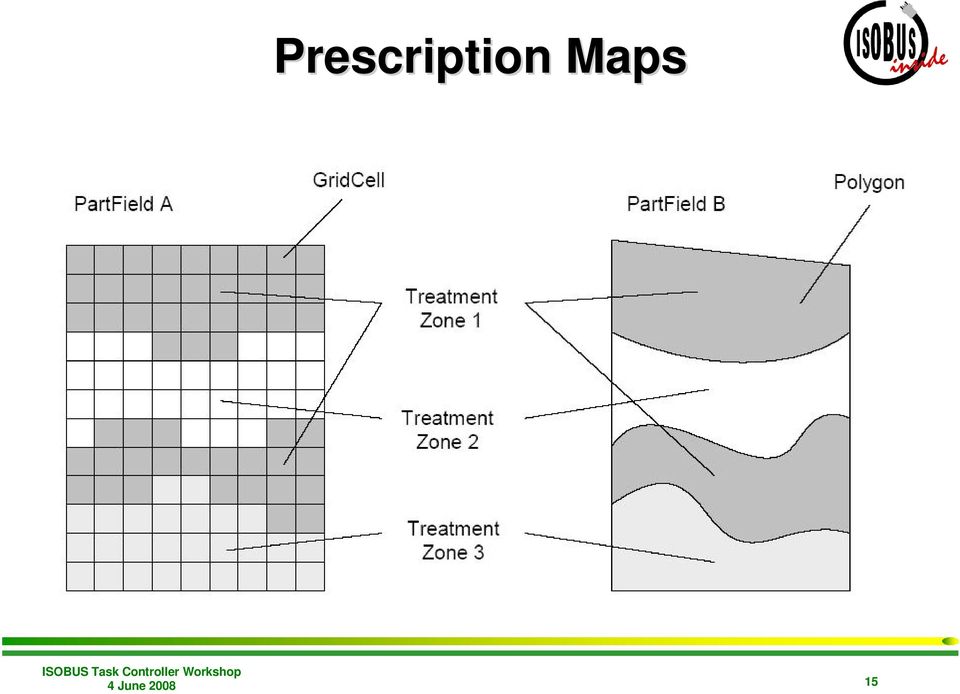
14 Site-specific Application TC and WS may support prescriptions (WS defines e.g. its application rate as set-able in its DCD) Application map gets planed at Desktop PC Application map gets attached to XML Task file as Grid or Shape File TC opens application map in the field TC determines the appropriate application rate based on GPS position in the application map TC may takes offset of GPS to drop point into account (e.g. distance between GPS and Sprayer Boom) TC sends the new application rate to the correct object of the connected WS WS applies the new application rate when appropriate (e.g. Manual versus Auto Mode) WS sends new current rate for documentation purpose 14

15 Prescription Maps 15
16 Grid Definition 16

17 Data Page: Process Data Message (PDM) PDU Format: PDU Specific: Destination specific Default Priority: PGN: Details are defined in Part 7 annex A and Part 10 Annex B (0xCB00) Technical Data Message (Command 0 or 1): Layout of Data Bytes Command Sub Com Command Specific Parameters 4 bits 4 bits 56 bits Byte 1 Byte 2-8 Request TC Spec Version Response TC Spec Version = 0xFF Byte 2 = version Byte 3-8 = 0xFF Request DCD Structure Label = 0xFF Response DCD Structure Label char DCD Structure Label => NACK message will be replied when DCD doesn t exist 17

18 Process Data Message (PDM) Technical Data Message (cont d): Layout of Data Bytes Command Sub Com Command Specific Parameters 4 bits 4 bits 56 bits Byte 1 Byte 2-8 Request DCD Localization Label (WS to TC) Response DCD Localization Label (TC to WS) Request DCD Pool transfer (WS to TC) Response DCD Pool transfer (TC to WS) = 0xFF char DCD Localization Label Byte 2-5 = DCD size in Byte Byte 6-8 = 0xFF Byte 2 = Memory Status Byte 3-8 = 0xFF DCD Pool transfer (WS to TC) DCD Pool transfer Response (TC to WS) ** Requires TP or ETP Byte 2-n = DCD Objects ** Byte 2 = error code Byte 3-6 = Bytes received Byte 7-8 = 0xFF 18
 DCD Pool transfer Response (TC to WS) ** Requires TP or ETP 0001 0110 0001 0111 Byte 2-n = DCD Objects ** Byte 2 = error code Byte 3-6 = Bytes received Byte 7-8 =")
19 Process Data Message (PDM) Technical Data Message (cont d): Layout of Data Bytes Command Sub Com Command Specific Parameters 4 bits 4 bits 56 bits Byte 1 Byte 2-8 DCD activation (WS to TC) DCD activation Response (TC to WS) DCD Pool Delete message (WS to TC) DCD Pool Delete response (TC to WS) Byte 2-8 = 0xFF Byte 2 = error code Byte 3-8 = further info on error Byte 2-8 = 0xFF Byte 2 = error code Byte 3-8 = 0xFF Change Designator message (WS to TC) DCD Pool transfer Response (TC to WS) ** Requires TP or ETP Byte 2-3 = Object ID Byte 4 = Number of Chars Byte 5-n = Designator ** Byte 2-3 = Object ID Byte 4 = error code Byte 5-8 = 0xFF 19
 ** Requires TP or ETP 0001 1100 0001 1101 Byte 2-3 = Object ID Byte 4 = Number of Chars Byte 5-n = Designator ** Byte 2-3 = Object ID Byte 4 = error code")
20 Process Data Message (PDM) Process Variable Handling: Layout of Data Bytes Command Element Number Data Dictionary Identifier (DDI) Process Variable Value Com Element # 4 bits Byte 1 DDI Process Variable Value 12 bits 16 bits 32 bits Byte 2 Byte 3 Byte 4 Byte 5 Byte 6 Byte 7 Byte 8 Defines the action to be taken Defines the addressed Object in the DCD Reason: not enough space in the PDM for the complete Object ID Specifies the accessed parameter of the DCD Element Details defined in Part 11 (online db) Contains the actual data of the PDM The definition depends on the Command. 20
 Contains the actual data of the PDM The definition depends on")
21 Process Data Message (PDM) Process Variable Handling (cont d): Command 0x00 & 0x01 0x02 0x03 0x04 0x05 0x06 0x07 Meaning Technical Data Message Manual Value Request (TC to WS) Value Command a) actual value send from WS to TC (e.g. response to Manual Value Request) b) TC to WS in case of prescription for instance Time based Measurement Command (TC to WS) The Process Variable Data defines the time interval. Distance based Measurement Command (TC to WS) The Process Variable Data defines the distance interval. Minimum Threshold Measurement Command (TC to WS) The Process Variable Data defines the minimum value the object needs to have before the element gets send. Maximum Threshold Measurement Command (TC to WS) The Process Variable Data defines the maximum value up to the element gets send 21
22 Process Data Message (PDM) Process Variable Handling (cont d): Command 0x08 0x09-0x0C 0x0D 0x0E 0x0F Meaning On-Change Threshold (TC to WS) The WS sends the process data value only when the change since last transmission is larger than the threshold. Reserved Negative Acknowledgement (NACK) Send when the command got rejected for reason included in Process Data value. Task Controller Status (TC to global) Cyclic status message send every 2 seconds after completion of start-up sequence. The WS Master time out of the connection after this message fails for 6 seconds. Includes the Task Status in the Process Data value field, which triggers the overall system. Working Set Task Status (WS to TC) Each individual WS indicates its availability by sending this message at a 2 second interval. The TC times out the connection after this message fails for 6 seconds. The task status gets reflected in the Process Data value field. 22
23 Process Data Trigger Methods o Supported Trigger Methods are defined per Process Data Variable in the DCD o Based on Triggers the values are only send while the Task Status is 1 o The manual request of values works at any time (independent of Task Status) o The TC can define individual limitations for the Triggers activated for a particular Process Data Value. Combination of Trigger Methods: o Time interval, distance interval and on-change can be used in any combination, while any of the three triggers occurring first resets all three trigger counters for that value. o All three trigger methods can be combined with the Min- and Max-Threshold, while the value is only send when it stays within the Threshold limitations. o If the Min-Threshold limitation is smaller than the Max-Threshold limitation, then the logging is active while the value is in-between the two limitations. Logging inactive o If the Min-Threshold limitation is larger than the Max-Threshold limitation, then the logging is active while the value is below the Max-Threshold or above the Min-Threshold. Logging active Min Max Logging active Logging inactive Max Min Logging inactive Logging active See Part 10 Annex D DataLogTrigger (DLT) for more details! 23
24 Process Data Trigger Methods What does this mean for the design of a TC-module in a Working Set? The WS TC-module needs to o know which Device Process Data Objects (DPD) are available per DCD Element - to filter incoming trigger commands etc - to forward incoming value changes to correct Element in the application o know which triggers are supported for each individual DPD - to filter incoming trigger commands o know which triggers are set per DPD - to enable the internal trigger handling accordingly o know which limits are defined for individual triggers and DPD - to feed the internal trigger handling accordingly o handle individual variables per trigger and DPD (e.g. Thresholds, etc) to ensure independent handling o apply the rules for combinations of trigger methods per DPD etc o store the current value (actual rate) independent of the commanded value (e.g. prescription rate) - to allow the application to decide when it applies a new commanded value to its operation (Manual versus Automatic mode) - to report the actually used value to the TC while the last commanded value didn t get applied yet 24
25 Device Configuration Data (DCD) o Also referred to as Device Description Data (DDD) o The DCD describes the connected Working Set for the TC and Desktop SW - Number of bins (tanks), booms, sections - the structural relationship between the objects (sections are children to a boom, etc) - the offsets of the objects to each other (x-, y-, z-offset) - which Process Data Variables a particular DCD element supports (e.g. boom supports on/off status and current application rate) - version, embedded language and unit settings (localization label) o A valid DCD has to be available per Working Set for a standard TC communication - either as runtime upload via CAN at system start-up - or offline via import into Desktop SW 25
26 Device Configuration Data (DCD) The Object Hierarchy: 26
27 Device Configuration Data (DCD) Device Element Object (DET): o Multiple objects of type DET represent the machine functions o Object Fields: o Object ID o Object Designator (string may be displayed by the TC) o Device Element Types o Device represents the overall machine (e.g. sprayer) o Function generic object to represent sensors, booms, etc o Bin Sprayer tanks or planter bins, etc o Section represents individual row units for planters, sprayers, etc o Unit Sub-units of Sections (e.g. nozzles of a sprayer section) o Connector Connection point between different WS (e.g. at the back of the tractor and at the front of the drawbar) o Nav. Ref. Point Mounting location for GPS receivers etc o Device Element Number individual number used to identify this object in the PDM o Parent Device Element ID (section objects point to their boom etc) o List Object IDs of Child Objects o Each DCD has to have one DET object of type Device representing the machine 27
28 Device Configuration Data (DCD) Device Object (DVC): o Each DCD has to have one DVC object o Represents the overall DCD o Object Fields: o Object ID o Object Designator (string may be displayed by the TC) o Software Version of the related application o NAME of owning WS Master o Serial Number of WS Master o Structure Label Proprietary information about the machine configuration represented by the DCD o Localization Label Unit and Language settings represented by the DCD 28
29 Device Configuration Data (DCD) Device Process Data Object (DPD): o DPD objects represent the values (DDI) supported by the parent object for recording etc, e.g. - current application rate - application rate set-point (for prescription) - on/of status o Object Fields: o Object ID o Object Designator (string may be displayed by the TC) o Process Data Element ID (DDI as specified in part 11 db) o Process Data properties - DDI is set-able => the TC can prescribe this value - DDI is part of Default Data Set of this WS o Supported Trigger Methods - time and distance interval - min and max threshold limits - on-change - total counter o Reference to Device Value Presentation Object (Object ID) 29
30 Device Configuration Data (DCD) Device Property Object (DPT): o DPT objects represent fixed values which don t change during operation; e.g. - x-, y-, z-offsets - bin-size o Object Fields: o Object ID o Object Designator (string may be displayed by the TC) o Process Data Element ID (DDI as specified in part 11 db) o Property Value (actual fixed value of this DDE) o Reference to Device Value Presentation Object (Object ID) 30
31 Device Configuration Data (DCD) Device Value Presentation Object (DVP): o DVP objects define how the value of the parent object may be displayed to the operator in terms of units, value scaling, etc o Object Fields: o Object ID o Object Designator (string may be displayed by the TC) o Offset to be applied before displaying the value o Scale to be applied before displaying the value o Number of Decimals (number of digits behind decimal point) o Unit Designator String 31
32 Device Configuration Data (DCD) Task Controller Device geometry definitions 32
33 Device Configuration Data (DCD) The Object reference Coordinate System: forward + x left -y up - z down + z right + y backward -x x-axis is specified as positive in normal driving direction y-axis is specified as positive to the right of the normal driving direction z-axis is specified as positive downward towards the ground 33
34 Data Dictionary Element (DDE) What information contains the DDE? o DDE s are defined in the online db of part 11 (see o A DDE includes the following information o Unique Identifier (DDI) o Clear definition o Unit definition o Value Range o Resolution o Diagnostic information (SPN) o Comments o Device Class supported by the DDE o db allows to download all DDE s defined into an Excel Spreadsheet o Requests for new DDE s are evaluated and assigned by an international Expert Team 34
35 Part 11 online db 35
36 o Sprayer with 9 Sections o Each Section provides o its on/off status o its working width o Y-offset (left to right) DCD Example o The Boom provides o Target Rate (set-able) o Application Rate o Master Valve on/off status o Total Volume applied o Total Area sprayed o Total Distance Driven o Total Time o its x-offset (in driving direction) o Several additional information like Device Value Presentation objects per offset etc are missing 36
37 John Deere Infrastructure Data Dictionary Element (DDE) ID Definition Units Range Resolution 6 - Set-point Mass per Area Application Rate Set-point Application Rate specified as mass per Area mg / m² mg / m² t / m² lb / foot² 1.0 / bit Farm Management Computer ISO11783 XML File Format Any Manufacturer Apex Pref. Partner JD Converter GreenStar Proprietary File Format DDE DDE Data Dictionary Implemented as Online db SAE SPN Comments Device Class not specified none 4 - Planter 5 - Fertilizer 6 - Sprayer VT GS 2 Display Field Doc Task Controller DDE DDE ISO11783 GreenStar Process Data proprietary Message (CAN) JDGUI OP VI engine JDOS TC engine DCD DCD Tool Application Software JD ISOBUS ECU 37
38 Question / Answer Session 38
Section Contents ISOBUS GENERAL INFORMATION...3. What is ISOBUS?... 3 Connectors... 5 CANBUS GENERAL INFORMATION...7
 PFP13080 About This Document This user guide will help you learn about. It will explain: Hardware, such as connectors Settings necessary on a John Deere display to support implements Theory of operation
ISO11783 a Standardized Tractor Implement Interface
 ISO a ized Tractor Implement Interface Peter Fellmeth, Vector Informatik GmbH The upcoming ISO standard will be the preferred tractor Implement interface in the agricultural industry. Therefore the ISO
I SO wish it were that easy! The challenge of ISOBUS Implementation
 Precision Farming Challenges in the 21 st Century I SO wish it were that easy! The challenge of ISOBUS Implementation Peter Nelson Engineering Director RDS Technology Ltd. What is ISOBUS? ISOBUS is a standard
RPDO 1 TPDO 1 TPDO 5 TPDO 6 TPDO 7 TPDO 8
 EN ZC - 6DI8DO CANopen I/O Module 6 Digital Input 8 Digital Output Or 8 Counters (3 bit) 8 Digital input 8 Digital output User Manual Contents: Features PDOs PDO Type Emergency Message Functional Diagrams
ETS4 Diagnostics. KNX Association
 ETS4 Diagnostics Table of Contents 1 Diagnostics and fault location... 3 2 Diagnostics: Individual addresses...... 4 2.1 Devices in Programming Mode... 4 2.2 Checking if an address exists and locating
ISOBUS s Past, Present and Future role in Agricultural Robotics and Automation
 1 / 42 ISOBUS s Past, Present and Future role in Agricultural Robotics and Automation Benjamin Fernandez Universidad Nacional de Educación a Distancia (UNED) Departamento de Ingeinería de Software y Sistemas
WA Manager Alarming System Management Software Windows 98, NT, XP, 2000 User Guide
 WA Manager Alarming System Management Software Windows 98, NT, XP, 2000 User Guide Version 2.1, 4/2010 Disclaimer While every effort has been made to ensure that the information in this guide is accurate
WIZnet S2E (Serial-to-Ethernet) Device s Configuration Tool Programming Guide
 Device s Configuration Tool Programming Guide") WIZnet S2E (Serial-to-Ethernet) Device s Configuration Tool Programming Guide Rev 0.2 This document describes how to make your own Configuration Tool for WIZ100SR, WIZ105SR and WIZ110SR of WIZnet. And
WIZnet S2E (Serial-to-Ethernet) Device s Configuration Tool Programming Guide Rev 0.2 This document describes how to make your own Configuration Tool for WIZ100SR, WIZ105SR and WIZ110SR of WIZnet. And
TSX ETY 110 Module 8
 Module 8 Introduction Subject of this chapter What s in this Chapter? This chapter describes the implementation of a TSX ETY 110 module. This chapter contains the following sections: Section Topic Page
LDCDP 11999.GdW. L force Controls. Ä.GdWä. Software Manual. Industrial PC. WindowsR CE Thin Client. Operating system
 L force Controls Ä.GdWä LDCDP 11999.GdW Software Manual Industrial PC WindowsR CE Thin Client Operating system l Please read these instructions before you start working! Follow the enclosed safety instructions.
Real Time Monitor. A Real-Time Windows Operator Interface. DDE Compliant. (for remote data display)
") Real Time Monitor A Real-Time Windows Operator Interface DDE Compliant (for remote data display) TABLE OF CONTENTS 1. INTRODUCTION...1 1.1 INSTALLATION...2 1.2 FIRST START UP - DDE CONFIGURE...2 1.3 AUTO-STARTUP...2
Real Time Monitor A Real-Time Windows Operator Interface DDE Compliant (for remote data display) TABLE OF CONTENTS 1. INTRODUCTION...1 1.1 INSTALLATION...2 1.2 FIRST START UP - DDE CONFIGURE...2 1.3 AUTO-STARTUP...2
OPERATORS MANUAL. ISO Drill Manager Ver. 1.21B
 OPERATORS MANUAL ISO Drill Manager Ver. 1.21B HORSCH LLC 2013 Rev. B Page 2 ISO Drill Manager Operator s Manual Table of Contents Table of Contents Table of Contents...3 Introductory Information...5 Read
Local Interconnect Network Training. Local Interconnect Network Training. Overview
 Overview Local Interconnect Network Training History and introduction Technical features The ISO/OSI reference model and LIN Frames Message Frames Communication concept of LIN Command Frames and Extended
User Manual Microsoft Dynamics AX Add-on LabAX Label Printing
 User Manual Microsoft Dynamics AX Add-on LabAX Label Printing Version 1.7 Last Update: 17.04.2011 User Manual Microsoft Dynamics AX Add-on LabAX Label Printing Page 2 / 23 Contents 1 Introduction... 3
13-1. This chapter explains how to use different objects.
 13-1 13.Objects This chapter explains how to use different objects. 13.1. Bit Lamp... 13-3 13.2. Word Lamp... 13-5 13.3. Set Bit... 13-9 13.4. Set Word... 13-11 13.5. Function Key... 13-18 13.6. Toggle
Technical Support Bulletin Nr.18 Modbus Tips
 Technical Support Bulletin Nr.18 Modbus Tips Contents! Definitions! Implemented commands! Examples of commands or frames! Calculating the logical area! Reading a signed variable! Example of commands supported
Virtual Integrated Design Getting started with RS232 Hex Com Tool v6.0
 Virtual Integrated Design Getting started with RS232 Hex Com Tool v6.0 Copyright, 1999-2007 Virtual Integrated Design, All rights reserved. 1 Contents: 1. The Main Window. 2. The Port Setup Window. 3.
CONCEPT1 RS232 COMMUNICATION
 Concept 1 RS-232 Communication Communication with Concept 1 via RS-232 is done with simple ASCII Commands and Replies. The port settings are 19200Baud, 8bits, no parity and 1 stop bit. The physical connection
ScanWin Installation and Windows 7-64 bit operating system
 ScanWin Installation and Windows 7-64 bit operating system In order to run the ScanWin Pro install and program on Windows 7 64 bit operating system you need to install a Virtual PC and then install a valid,
Table 1 below is a complete list of MPTH commands with descriptions. Table 1 : MPTH Commands. Command Name Code Setting Value Description
 MPTH: Commands Table 1 below is a complete list of MPTH commands with descriptions. Note: Commands are three bytes long, Command Start Byte (default is 128), Command Code, Setting value. Table 1 : MPTH
FileMaker Server 11. FileMaker Server Help
 FileMaker Server 11 FileMaker Server Help 2010 FileMaker, Inc. All Rights Reserved. FileMaker, Inc. 5201 Patrick Henry Drive Santa Clara, California 95054 FileMaker is a trademark of FileMaker, Inc. registered
LENORD. +BAUER... automates motion. Fieldbus connection absolute encoders CANopen. Reference. Communication profile DS-301 Device profile DS-406
 Fieldbus connection absolute encoders CANopen Communication profile DS-30 Device profile DS-406 LENORD +BAUER... automates motion. Reference D-0R-xCO (.) Right to technical changes and errors reserved.
eztcp Technical Document Modbus/TCP of eztcp Caution: Specifications of this document may be changed without prior notice for improvement.
 eztcp Technical Document Modbus/TCP of eztcp Version 1.3 Caution: Specifications of this document may be changed without prior notice for improvement. Sollae Systems Co., Ltd. http://www.sollae.co.kr Contents
DiskPulse DISK CHANGE MONITOR
 DiskPulse DISK CHANGE MONITOR User Manual Version 7.9 Oct 2015 www.diskpulse.com [email protected] 1 1 DiskPulse Overview...3 2 DiskPulse Product Versions...5 3 Using Desktop Product Version...6 3.1 Product
GreenStar Software Update 2016-1 Release Notes
 Important Notes: GreenStar Software Update 2016-1 It is recommended to back up GreenStar 2 1800 Display and GreenStar 3 2630 Display data prior to updating to Software Update 16-1, as a precaution to protect
ModBus Server - KNX. Gateway for integration of KNX equipment into Modbus (RTU and TCP) control systems.
 control systems.") IntesisBox ModBus Server - KNX Gateway for integration of KNX equipment into Modbus (RTU and TCP) control systems. Integrate KNX based lighting control into your SCADA, BMS, PLC "talking" Modbus. Master
IntesisBox ModBus Server - KNX Gateway for integration of KNX equipment into Modbus (RTU and TCP) control systems. Integrate KNX based lighting control into your SCADA, BMS, PLC "talking" Modbus. Master
Kramer Electronics, Ltd. Site-CTRL and Web Access Online User Guide (Documentation Revision 2)
") Kramer Electronics, Ltd. Site-CTRL and Web Access Online User Guide (Documentation Revision 2) Software Version 1.9. 2902 To check that you have the latest version, go to the DOWNLOADS section of our Web
Kramer Electronics, Ltd. Site-CTRL and Web Access Online User Guide (Documentation Revision 2) Software Version 1.9. 2902 To check that you have the latest version, go to the DOWNLOADS section of our Web
Product Information CANalyzer.J1939
 Product Information CANalyzer.J1939 Table of Contents 1 Introduction... 3 1.1 Application Areas... 3 1.2 Features and Advantages... 3 1.3 Further Information... 3 2 Functions... 4 3 Hardware Interfaces...
NortechCommander Software Operating Manual MAN-00004 R6
 NortechCommander Software Operating Manual MAN-00004 R6 If the equipment described herein bears the symbol, the said equipment complies with the applicable European Union Directive and Standards mentioned
Cart Interface Installation & Control Board Manual for M38 XP and RX Carts and Legacy M39 Carts
 Rubbermaid Medical Solutions Cart Interface Installation & Control Board Manual for M38 XP and RX Carts and Legacy M39 Carts REVISED FEBRUARY 25, 2010 Filename: Cart Interface Installation & Control Board
Modbus Protocol. PDF format version of the MODBUS Protocol. http://www.http://www.modicon.com/techpubs/toc7.html. The original was found at:
 Modbus Protocol PDF format version of the MODBUS Protocol The original was found at: http://www.http://www.modicon.com/techpubs/toc7.html (In case of any discrepancies, that version should be considered
Different Ways of Connecting to. 3DLevelScanner II. A.P.M Automation Solutions LTD. www.apm-solutions.com Version 3.0
 3DLevelScanner II Different Ways of Connecting to 3DLevelScanner II A.P.M Automation Solutions LTD. www.apm-solutions.com Version 3.0 2 Different Ways of Connecting to 3DLevelScanner II Version 3.0 Table
Type Message Description Probable Cause Suggested Action. Fan in the system is not functioning or room temperature
 Table of Content Error Messages List... 2 Troubleshooting the Storage System... 3 I can t access the Manager... 3 I forgot the password for logging in to the Manager... 3 The users can t access the shared
Hydras 3 LT Quick Start
 Catalog Number 6234218 Hydras 3 LT Quick Start SOFTWARE MANUAL December 2005, Edition 2 Hach Company, 2005. All rights reserved. Printed in the U.S.A. Catalog Number 6234218 Hydras 3 LT SOFTWARE MANUAL
Brunata Optuna W (171)
") Brunata Optuna W (171) Communication description Edition 1.1 UK-QB101414 / 26.02.2013 Brunata a/s is a Danish owned company. We have more than 90 years of experience within developing and producing meters,
Brunata Optuna W (171) Communication description Edition 1.1 UK-QB101414 / 26.02.2013 Brunata a/s is a Danish owned company. We have more than 90 years of experience within developing and producing meters,
Software Manual RS232 Laser Merge Module. Document # SU-256521-09 Rev A
 Laser Merge Module Document # SU-256521-09 Rev A The information presented in this document is proprietary to Spectral Applied Research Inc. and cannot be used for any purpose other than that for which
LEN s.r.l. Via S. Andrea di Rovereto 33 c.s. 16043 CHIAVARI (GE) Tel. +39 0185 318444 - Fax +39 0185 472835 mailto: [email protected] url: http//www.len.
 Tel. +39 0185 318444 - Fax +39 0185 472835 mailto: len@len.it url: http//www.len.") MA511 General Index 1 INTRODUCTION... 3 1.1 HARDWARE FEATURES:... 4 2 INTERFACE... 5 2.1 KEYBOARD... 6 2.2 POWER ON... 7 2.3 POWER OFF... 7 2.4 DETECTOR CONNECTION... 7 2.5 DETECTOR SUBSTITUTION...7 3
MA511 General Index 1 INTRODUCTION... 3 1.1 HARDWARE FEATURES:... 4 2 INTERFACE... 5 2.1 KEYBOARD... 6 2.2 POWER ON... 7 2.3 POWER OFF... 7 2.4 DETECTOR CONNECTION... 7 2.5 DETECTOR SUBSTITUTION...7 3
1. Make sure that no client accounts are open. 2. Click on Setup, then click Modem. The Modem Setup window will appear.
 SECURITY SYSTEM MANAGEMENT SOFTWARE FOR WINDOWS WINLOAD MODEM SETUP The modem setup is a very important step in the connection process. If the modem setup is not properly completed communication between
DriveRight. Fleet Management Software. Getting Started Guide. CarChip. DriveRight. Drivers. Vehicles. Product #8186
 DriveRight Fleet Management Software Getting Started Guide CarChip DriveRight Drivers Vehicles Product #8186 DriveRight Fleet Management Software Getting Started Guide; P/N 8186 Davis Instruments Part
Interface Protocol v1.2
 Interface Protocol v1.2 Uart Configure on PC Baud Rate Bits Stop bits Parity 9600 bps 8 Bits 1 Bit No Parity Basic Uart Transfer Format Start 0/1 : These bytes are both 0x55. Control : This byte is controling
ISOBUS VT. ISOBUS Virtual Terminal. User Manual HY33-4010-IB/UK
 ISOBUS VT ISOBUS Virtual Terminal User Manual HY33-4010-IB/UK Vansco Electronics Oy (Parker Hannifin Corporation) Electronic Controls Division PO Box 86 (Tiilenlyöjänkatu 5) FI-30101 Forssa, Finland Office
IntesisBox KNX LG Air Conditioning
 IntesisBox KNX LG Air Conditioning Gateway for integration of LG Air Conditioners with KNX control systems. 1. Main Features Direct connection to KNX TP-1 (EIB) bus. Direct connection to LG outdoor unit
Table of Contents 1. Introduction... 3 2. Installing Sxblue Server... 4 3. Principle of Operation... 6 4. Server Configuration... 7 4.
 SXBlue Server Table of Contents 1. Introduction... 3 2. Installing Sxblue Server... 4 3. Principle of Operation... 6 4. Server Configuration... 7 4.1 Server Status... 7 4.1.1 Info Clients... 8 4.1.2 Infos
The Answer to the 14 Most Frequently Asked Modbus Questions
 Modbus Frequently Asked Questions WP-34-REV0-0609-1/7 The Answer to the 14 Most Frequently Asked Modbus Questions Exactly what is Modbus? Modbus is an open serial communications protocol widely used in
Application Note. Introduction AN2471/D 3/2003. PC Master Software Communication Protocol Specification
 Application Note 3/2003 PC Master Software Communication Protocol Specification By Pavel Kania and Michal Hanak S 3 L Applications Engineerings MCSL Roznov pod Radhostem Introduction The purpose of this
SenseLink TM. End-Point Controller. Addendum
 SenseLink TM End-Point Controller Addendum MKS Instruments, Inc. Control & Information Technology Products Group 3350 Scott Blvd Bldg 4 Santa Clara, CA 95054 Main: 408.235.7620 Fax: 408.235.7625 SenseLink
BASLER ACE QUICK INSTALLATION GUIDE
 BASLER ACE QUICK INSTALLATION GUIDE Rev. 01 Quick installation Guide V1 1 Introduction The installation procedures in this guide assume that you want to get your camera operational and begin capturing
Easy Manage Helpdesk Guide version 5.4
 Easy Manage Helpdesk Guide version 5.4 Restricted Rights Legend COPYRIGHT Copyright 2011 by EZManage B.V. All rights reserved. No part of this publication or software may be reproduced, transmitted, stored
In-Vehicle Networking
 In-Vehicle Networking SAE Network classification Class A networks Low Speed (
Portal Connector Fields and Widgets Technical Documentation
 Portal Connector Fields and Widgets Technical Documentation 1 Form Fields 1.1 Content 1.1.1 CRM Form Configuration The CRM Form Configuration manages all the fields on the form and defines how the fields
Model 288B Charge Plate Graphing Software Operators Guide
 Monroe Electronics, Inc. Model 288B Charge Plate Graphing Software Operators Guide P/N 0340175 288BGraph (80207) Software V2.01 100 Housel Ave PO Box 535 Lyndonville NY 14098 1-800-821-6001 585-765-2254
GETTING STARTED WITH LABVIEW POINT-BY-POINT VIS
 USER GUIDE GETTING STARTED WITH LABVIEW POINT-BY-POINT VIS Contents Using the LabVIEW Point-By-Point VI Libraries... 2 Initializing Point-By-Point VIs... 3 Frequently Asked Questions... 5 What Are the
Plug-In for Informatica Guide
 HP Vertica Analytic Database Software Version: 7.0.x Document Release Date: 2/20/2015 Legal Notices Warranty The only warranties for HP products and services are set forth in the express warranty statements
MCB3101 (Class I) WiRobot Serial Bluetooth Wireless Module User Manual
 WiRobot Serial Bluetooth Wireless Module User Manual") MCB3101 (Class I) WiRobot Serial Bluetooth Wireless Module User Manual Version: 1.0.1 Dec. 2005 Table of Contents I. Introduction 2 II. Operations 2 II.1. Theory of Operation 2 II.2. Configuration (PC-PC
MCB3101 (Class I) WiRobot Serial Bluetooth Wireless Module User Manual Version: 1.0.1 Dec. 2005 Table of Contents I. Introduction 2 II. Operations 2 II.1. Theory of Operation 2 II.2. Configuration (PC-PC
IntelliAg/ISO Bus Virtual Terminal
 IntelliAg/ISO Bus Virtual Terminal (IntelliAg system used with a non DICKEY-john Virtual Terminal/Planter Monitor functionality only) TABLE OF CONTENTS... 1 Installation... 2 Startup... 3 Touchkey Symbol
10 Thomas, Irvine, CA 92618 USA Tel: (949) 465-0900 Fax: (949) 465-0905 Toll Free: (800) 23 FUTEK
 465-0900 Fax: (949) 465-0905 Toll Free: (800) 23 FUTEK") Table of Contents Software Overview... - 4 - Product Key... - 5 - Model Selection... - 6 - Device Selection... - 7 - Menu... - 8 - File... - 8 - Edit... - 8 - View... - 8 - Format... - 8 - Help... - 9
Table of Contents Software Overview... - 4 - Product Key... - 5 - Model Selection... - 6 - Device Selection... - 7 - Menu... - 8 - File... - 8 - Edit... - 8 - View... - 8 - Format... - 8 - Help... - 9
Software User Guide UG-461
 Software User Guide UG-461 One Technology Way P.O. Box 9106 Norwood, MA 02062-9106, U.S.A. Tel: 781.329.4700 Fax: 781.461.3113 www.analog.com ezlinx icoupler Isolated Interface Development Environment
User Guide Win7Zilla
 User Guide Win7Zilla Table of contents Section 1: Installation... 3 1.1 System Requirements... 3 1.2 Software Installation... 3 1.3 Uninstalling Win7Zilla software... 3 Section 2: Navigation... 4 2.1 Main
Egnyte for Salesforce v2.1 Administrator s Guide
 Egnyte for Salesforce v2.1 Administrator s Guide Overview Egnyte Tabs Egnyte Domain Configuration Egnyte Sync Configurations Creating Sync Configurations for standard and/or custom objects Creating folder
NVT (Network Virtual Terminal) description
 description") NVT (Network Virtual Terminal) description English version Czech version Communication with the TCP/IP device over the Ethernet network can be extended to more functions using NVT (Network Virtual Terminal)
NVT (Network Virtual Terminal) description English version Czech version Communication with the TCP/IP device over the Ethernet network can be extended to more functions using NVT (Network Virtual Terminal)
UM0853 User manual. 1 Introduction. M24LRxx application software user guide
 User manual M24LRxx application software user guide 1 Introduction The purpose of this user manual is to teach how to use the M24LRxx tool kit with the M24LRxx_Application_Software. It describes the M24LRxx_Application_Software
www.imprezer.tk Introduction to www.union88.tk RACE FUELS Hans-Christian von der Wense Munich, Germany
 Introduction to Hans-Christian von der Wense Munich, Germany Overview Progress in Automotive Electronics and it s Impacts on Networking LIN Consortium LIN Concept Physical Layer Data Link Layer LIN Network
Dell SonicWALL SRA 7.5 Secure Virtual Meeting and Secure Virtual Assist
 Dell SonicWALL SRA 7.5 Secure Virtual Meeting and Secure Virtual Assist Document Scope This document describes how to configure and use the Dell SonicWALL SRA Secure Virtual Meeting feature and the Dell
User Guide. NAS Compression Setup
 NAS compression is not done on the recorder, it is a separate application normally requiring a dedicated machine (audio compression is extremely CPU intensive so need to be very careful about running it
Kaldeera Workflow Designer 2010 User's Guide
 Kaldeera Workflow Designer 2010 User's Guide Version 1.0 Generated May 18, 2011 Index 1 Chapter 1: Using Kaldeera Workflow Designer 2010... 3 1.1 Getting Started with Kaldeera... 3 1.2 Importing and exporting
KNX Panasonic Air Conditioners
 IntesisBox KNX Panasonic Air Conditioners Gateway for Panasonic ECOi and PACi system integration into KNX networks Up to 30 Outdoor units Up to 64 Indoor units PA-AC-KNX-64/128 EIA485 U1U2 line U1U2 line
FileMaker Server 10 Help
 FileMaker Server 10 Help 2007-2009 FileMaker, Inc. All Rights Reserved. FileMaker, Inc. 5201 Patrick Henry Drive Santa Clara, California 95054 FileMaker, the file folder logo, Bento and the Bento logo
Expat kiss_fft gsoap smartgwt Linux Qt md5 zlig log 4cpp sqlite gcc/g++/libc/libc++ gwt
 1 FAG Industrial Services GmbH Kaiserstraße 100 52134 Herzogenrath Germany +49 (0) 2407 9149-66 +49 (0) 2407 9149-59 [email protected] Web www.schaeffler.comservices All rights reserved.
Config software for D2 systems USER S MANUAL
 DT-CONFIG SOFTWARE Config software for D2 systems USER S MANUAL CONTENTS 1. Introductions ------------------------------------------------------------------- 3 2. System Requirement and Connection ----------------------------------------
Quick Start Guide RIVA/Athena Sea-Doo ECU
 Quick Start Guide RIVA/Athena Sea-Doo ECU PART# - RS11891-ECU-DC APPLICATION(S): Sea-Doo 260/255/215hp icontrol Models RIVA/Athena ECU Manager Web Site: www.rivaathena.com NOTE: YOU MUST PERFORM PHYSICAL
EMR 3 CAN BUS specification
 EMR 3 CAN BUS specification Version 11-3 Overview 1. SAE J1939-Standard CAN Messages... 3 1.1. EEC1:... 3 1.2. EEC2:... 5 1.3. Engine Temperature:... 6 1.4. Engine Fluid Level / Pressure:... 7 1.5. Inlet
OIL PRESS 71.8 PSI FUEL. Cloud based, diagnostic, engine monitoring and reporting system. www.faria-instruments.com www.beede.com
 OIL PRESS 71.8 PSI Cloud based, diagnostic, engine monitoring and reporting system www.faria-instruments.com www.beede.com Start Updating Send Data The Faria EntelNet service is a multi part system which
Monitoring Replication
 Monitoring Replication Article 1130112-02 Contents Summary... 3 Monitor Replicator Page... 3 Summary... 3 Status... 3 System Health... 4 Replicator Configuration... 5 Replicator Health... 6 Local Package
CS 326e F2002 Lab 1. Basic Network Setup & Ethereal Time: 2 hrs
 CS 326e F2002 Lab 1. Basic Network Setup & Ethereal Time: 2 hrs Tasks: 1 (10 min) Verify that TCP/IP is installed on each of the computers 2 (10 min) Connect the computers together via a switch 3 (10 min)
Product Manual. ABB i-bus KNX Data Logging Unit BDB/S 1.1. Intelligent Installation Systems ABB
 Product Manual ABB i-bus KNX Data Logging Unit BDB/S 1.1 Intelligent Installation Systems ABB This manual describes the function of the Data Logging Unit BDB/S 1.1. Subject to changes and errors excepted.
Jet Data Manager 2012 User Guide
 Jet Data Manager 2012 User Guide Welcome This documentation provides descriptions of the concepts and features of the Jet Data Manager and how to use with them. With the Jet Data Manager you can transform
SMS Alarm Messenger. Setup Software Guide. SMSPro_Setup. Revision 090210 [Version 2.2]
![SMS Alarm Messenger. Setup Software Guide. SMSPro_Setup. Revision 090210 [Version 2.2]](/thumbs/29/13662687.jpg "SMS Alarm Messenger. Setup Software Guide. SMSPro_Setup. Revision 090210 [Version 2.2]") SMS Alarm Messenger SMSPro_Setup Revision 090210 [Version 2.2] ~ 1 ~ Contents 1. How to setup SMS Alarm Messenger?... 3 2. Install the SMSPro_Setup software... 5 3. Connection Type... 6 4. Connection Port
SMS Alarm Messenger SMSPro_Setup Revision 090210 [Version 2.2] ~ 1 ~ Contents 1. How to setup SMS Alarm Messenger?... 3 2. Install the SMSPro_Setup software... 5 3. Connection Type... 6 4. Connection Port
How to read this guide
 How to read this guide The following shows the symbols used in this Quick start guide with descriptions and examples. Symbol Description Example P oint Reference Caution [ ] This symbol explains information
White Paper BMC Remedy Action Request System Security
 White Paper BMC Remedy Action Request System Security June 2008 www.bmc.com Contacting BMC Software You can access the BMC Software website at http://www.bmc.com. From this website, you can obtain information
To perform Ethernet setup and communication verification, first perform RS232 setup and communication verification:
 PURPOSE Verify that communication is established for the following products programming option (488.2 compliant, SCPI only): DCS - M9C & DCS M130, DLM M9E & DLM-M9G & DLM M130, DHP - M9D, P series, SG,
MetaXpress Image Acquisition and Analysis Software. Analysis Guide Version 2.0 for Microsoft Windows XP
 MetaXpress Image Acquisition and Analysis Software Analysis Guide Version 2.0 for Microsoft Windows XP 0112-0170 September 2008 This document is provided to customers who have purchased MDS Analytical
ODBC Client Driver Help. 2015 Kepware, Inc.
 2015 Kepware, Inc. 2 Table of Contents Table of Contents 2 4 Overview 4 External Dependencies 4 Driver Setup 5 Data Source Settings 5 Data Source Setup 6 Data Source Access Methods 13 Fixed Table 14 Table
MAS 500 Intelligence Tips and Tricks Booklet Vol. 1
 MAS 500 Intelligence Tips and Tricks Booklet Vol. 1 1 Contents Accessing the Sage MAS Intelligence Reports... 3 Copying, Pasting and Renaming Reports... 4 To create a new report from an existing report...
Windows Scheduled Task and PowerShell Scheduled Job Management Pack Guide for Operations Manager 2012
 Windows Scheduled Task and PowerShell Scheduled Job Management Pack Guide for Operations Manager 2012 Published: July 2014 Version 1.2.0.500 Copyright 2007 2014 Raphael Burri, All rights reserved Terms
Release Notes LS Retail Data Director 3.01.04 August 2011
 Release Notes LS Retail Data Director 3.01.04 August 2011 Copyright 2010-2011, LS Retail. All rights reserved. All trademarks belong to their respective holders. Contents 1 Introduction... 1 1.1 What s
IntesisBox KNX Modbus TCP master
 IntesisBox KNX TCP master Gateway for integration of TCP slave devices into KNX control systems. Integrate any TCP slave device into KNX. KNX TCP slave EIB Bus IntesisBox Ethernet slave LinkBoxEIB Configuration
Automation System TROVIS 6400 TROVIS 6493 Compact Controller
 Automation System TROVIS 6400 TROVIS 6493 Compact Controller For panel mounting (front frame 48 x 96 mm/1.89 x 3.78 inch) Application Digital controller to automate industrial and process plants for general
Alarms & Events Plug-In Help. 2015 Kepware, Inc.
 2015 Kepware, Inc. 2 Table of Contents Table of Contents 2 Alarms & Events Plug-In 3 Overview 3 OPC AE Plug-In Terminology 3 OPC AE Plug-In Conditions 4 The OPC AE Plug-In from the OPC AE Clients' Perspective
isppac-powr1220at8 I 2 C Hardware Verification Utility User s Guide
 November 2005 Introduction Application Note AN6067 The isppac -POWR1220AT8 device from Lattice is a full-featured second-generation Power Manager chip. As part of its feature set, this device supports
Inwall Room Temperature Unit
 Inwall Room Temperature Unit TM11B01KNX TM11B11KNX TM11B21KNX Product Handbook Product: Inwall Room Temperature Unit Order Code: TM11B01KNX TM11B11KNX TM11B21KNX Application Program ETS: TM11B_1KNX Inwall
Service Oriented Architecture for Agricultural Vehicles
 Service Oriented Architecture for Agricultural Vehicles Leipzig, 30.9.2010 8. Workshop Automotive Software Engineering Dr. G. Kormann, M. Hoeh, H.J. Nissen THE END of Embedded Software? www.electronics-ktn.com/
Multi-Touch Control Wheel Software Development Kit User s Guide
 Multi-Touch Control Wheel Software Development Kit User s Guide V3.0 Bulletin #1204 561 Hillgrove Avenue LaGrange, IL 60525 Phone: (708) 354-1040 Fax: (708) 354-2820 E-mail: [email protected] www.grayhill.com/instinct
Kurz MODBUS Client User s Guide
 Kurz MODBUS Client User s Guide Introduction The Kurz MODBUS Client program can be used to demonstrate how the Kurz MFTB and MFTA Series products can be used in a MODBUS protocol network. The program is
Modicon Modbus Protocol Reference Guide. PI MBUS 300 Rev. J
 Modicon Modbus Protocol Reference Guide PI MBUS 300 Rev. J 1 Modicon Modbus Protocol Reference Guide PI MBUS 300 Rev. J June 1996 MODICON, Inc., Industrial Automation Systems One High Street North Andover,
ACCESS 9340 and 9360 Meter Ethernet Communications Card 9340-60-ETHER
 User s Guide PMCM-ETHCC-0208 2/2008 ACCESS 9340 and 9360 Meter Ethernet Communications Card 9340-60-ETHER TABLE OF CONTENTS INTRODUCTION... 2 Supported Ethernet Protocols... 2 Hardware... 2 Meter Firmware...
CC-Link Network Monitor Function
 CC-Link Network Monitor Function Sample Screen Manual Mitsubishi Electric Corporation Using the Samples The sample screen data and files such as the instruction manual can be used upon agreement to the
Accounting Manager. User Guide A31003-P1030-U114-2-7619
 Accounting Manager User Guide A31003-P1030-U114-2-7619 Our Quality and Environmental Management Systems are implemented according to the requirements of the ISO9001 and ISO14001 standards and are certified
Getting Started with POS. Omni POS Getting Started Manual. switched on accounting
 Omni POS Getting Started Manual switched on accounting i i Getting Started with Omni POS Table Of Contents Overview...1 Setting up POS...2 Initial Steps...2 Tellers...2 POS Clearing Account...3 Printing...4
SharePoint Integration Framework Developers Cookbook
 Sitecore CMS 6.3 to 6.6 and SIP 3.2 SharePoint Integration Framework Developers Cookbook Rev: 2013-11-28 Sitecore CMS 6.3 to 6.6 and SIP 3.2 SharePoint Integration Framework Developers Cookbook A Guide
Application & Quick-Start Guide
 Model: CRMWIC Web Intelligent Controller 1 This document will illustrate various ways to connect and use a CRM-WIC as well as programming examples. When connecting CRM-WIC, the installer has several interface