- 1 - Wireless Modem Router User Guide
|
|
|
- Barnard Griffith
- 10 years ago
- Views:
Transcription
1 - 1 - Wireless Modem Router User Guide

2 Copyright Statement is the registered trademark of Shenzhen Tenda Technology Co., Ltd. All the products and product names mentioned herein are the trademarks or registered trademarks of their respective holders. Copyright of the whole product as integration, including its accessories and software, belongs to Shenzhen Tenda Technology Co., Ltd. No part of this publication can be reproduced, transmitted, transcribed, stored in a retrieval system, or translated into any language in any form or by any means without the prior written permission of Shenzhen Tenda Technology Co., Ltd. All photos and product specifications mentioned in this manual are for references only. Upgrades of software and hardware may occur; Tenda reserves the right to revise this publication and to make changes in the content hereof without obligation to notify any person or organization of such revisions or changes. If you would like to know more about our product information, please visit our website at

3 Table of Contents COPYRIGHT STATEMENT ABOUT THIS MANUAL CHAPTER1 GET TO KNOW YOUR WIRELESS ROUTER PRODUCT FEATURES PACKAGE CONTENTS CHAPTER 2 HARDWARE INSTALL Front Panel Back Panel CHAPTER 3 QUICK INTERNET SETUP LOG IN TO WEB MANAGER Using Setup Wizard Using Browser INTERNET SETUP QUICK WIRELESS SECURITY SETUP CHAPTER 4 ADVANCED SETTINGS DEVICE INFO ADVANCED SETUP Layer2 Interface WAN Service LAN Setup NAT Security Parental Control Quality of Service Routing DNS DSL UPnP Print Server (Available only in D301) Storage Service (Available only in D301) Interface Grouping IP Tunnel Certificate Multicast IPTV WIRELESS Basic Security MAC Filter Wireless Bridge Station Info

4 4.4 DIAGNOSTICS MANAGEMENT Settings System Logs Security Log SNMP Agent TR-069 Client Internet Time Access Control Update Software Reboot APPENDIX 1 CONFIGURE YOUR PC WINDOWS MAC APPENDIX 2 JOIN YOUR WIRELESS NETWORK WINDOWS XP WINDOWS MAC IPHONE/IPAD APPENDIX 3 FAQS APPENDIX 4 VPI/VCI LIST APPENDIX 5 REGULATORY COMPLIANCE INFORMATION

5 About This Manual This user manual describes how to install, configure, operate, and troubleshoot the modem router in a simple and easy-to-understand way

6 Chapter1 Get to Know Your Wireless Router This user guide applies to the following four models: D301 and D151. The D301 is used as an example throughout this user guide. The differences between the two products are listed below: Model Wireless Speed USB Port RJ45 Ports D M 1 4 D M none 4 Note: The USB-based features of Print Server and Storage Service are unavailable in D151 that is not built with a USB port. What it does The Wireless ADSL2+ Modem Router provides you with an easy and secure way to set up a wireless home network with fast access to the Internet over a high-speed digital subscriber line (DSL). Complete with a built-in ADSL modem, it is compatible with all major ADSL Internet service providers. It offers wireless speeds of up to 300 Mbps needed for demanding applications, such as large file transfers, streaming HD video, and multiplayer gaming. The unit comes with a wide range of premium features and applications such as IPv6, TR069, SNMP, Multicast, IP tunnel, ready share USB, IPTV service and parental controls, etc. Plus, with the router, you can access Internet via the ATM interface or Ethernet interface. Product Features Wireless N speeds up to 300 Mbps for streaming HD videos and online gaming in addition to basic Internet applications. All-in-one device combines a Built-in ADSL2+ modem, wired router, wireless router and switch Sharable USB lets you access and share files on an attached USB hard drive (available only in D301) Sharable Printer lets you print from your Windows computer to a connected USB printer (available only in D301) Advanced QoS helps prioritize media streaming and gaming applications for best entertainment experience Parental Control keeps your kids Internet experience safe using flexible and customizable filter settings One-touch WPS ensures a quick and secure network connection WEP and WPA/WPA2 are supported for advanced encryptions Compatibility: Works with all major ADSL Internet service providers (ISPs); Backward compatible with b/g - 6 -

7 WiFi devices Interchangeable LAN/WAN ports to schedule the Ethernet port to function either as a LAN or a WAN port Interchangeable LAN/IPTV to schedule the Ethernet port to function either as a LAN or an IPTV port Optional Ethernet and ADSL Uplinks: Access Internet via ADSL2+ Broadband Internet Service or an interchangeable LAN/WAN RJ-45 port Multiple Internet Connection Types: Bridging, PPPoE, IPoE, PPPoA, IPoA, dynamic IP and static IP IPTV Service lets your surf Internet while watching online TV 6000V lightning-proof design fits into lightning-intensive environment Strong driving capability up to 6.5Km transmission distance High speed ADSL speed up to 24Mbps downstream 1Mbps upstream Built-in firewall prevents hacker attacks Channel auto-select for optimum performance FDM technology enables telephoning, faxing and surfing activities to proceed simultaneously without mutual interference Other Advanced Features: IPv6, DDNS, virtual server, DMZ, port triggering, IP filter, MAC filter and UPnP, etc Tenda Setup Wizard for easy and fast installation and configuration Tenda Green: Use hardware Power On/Off and software WiFi On/Off buttons to turn on and off power and WiFi to save energy when not in use Package Contents Your box should contain the following items: Wireless Modem Router Phone cable Ethernet cable ADSL2+ filter Quick install guide Power adapter Resource CD If any of the parts are incorrect, missing, or damaged, keep the carton, including the original packing materials and contact your Tenda dealer for immediate replacement

8 Chapter 2 Hardware Install If you have not already set up your new router using the Quick Install Guide that comes in the box, this chapter walks you through the hardware install. To set up your Internet connection, see Chapter 2 Quick Internet Setup. Front Panel The LEDs on the device are described below: LED Status Description Power SYS WLAN ADSL LAN 1/2/3/4 WPS USB ( available only in D301) Solid Off Blinking Solid/Off Blinking Off Solid Slow Blink Fast Blink Solid Off Blinking Solid Solid Blinking Off Solid Off Power is supplied to the device. Power is not supplied to the device. System is functioning correctly. System is functioning incorrectly. Transferring data Wireless is disabled. Wireless is enabled. Physical connection failure. Synchronizing... ADSL connection is established. No connection established. Transferring data Connection is established. Client connected successfully. The WPS LED starts blinking if you pressed the WPS button on the device or interface. If there is no wireless clients connected, the WPS LED turns off after blinking for 2 minutes. Connection is successfully established on the USB port. Connection is not established on the USB port

9 Back Panel ON/OFF: Power switch to turn the router on or off. Note: Please use the included power adapter. Use of a power adapter with different voltage rating may damage the device. WPS/RESET: Press it for 1-3 seconds to enable WPS connection or 7 seconds to restore all configurations to factory defaults. LAN: Ethernet RJ-45 LAN ports to cable the device to the local network devices such as computers.lan: Ethernet RJ-45 LAN ports to cable the device to the local network devices such as computers. DSL: RJ-11 Asynchronous DSL (ADSL) port for connecting the device to a DSL line. Follow the diagram below to install the device


10 Chapter 3 Quick Internet Setup This chapter instructs you to quickly set up your Internet connection. The Quick Internet Setup applies only to ADSL Uplink mode. If you are not directly connecting to the ADSL line via a phone cable, please click the Advanced button on the home page and then select Advanced Setup -> Layer2 Interface -> ETH Interface. For more information, see To set up the ETH interface and To setup WAN Service for ETH Interface. 2.1 Log in to Web Manager You can log in to the modem router s web manager with the Setup Wizard on the included CD automatically or using a web browser manually. The Setup Wizard on the auto-run CD can automatically configure your PC s TCP/IP properties and direct you to the web login window without requiring the IP address. Using Setup Wizard 1. Insert the included resource CD into your computer s drive and the CD automatically runs. If the CD does not run automatically, double click. You will see the screen below. 2. Click Run and it will automatically configure your PC s TCP/IP properties. If your PC is successfully configured, the login window below will display. Using Browser 1. Set your PC to Obtain an IP address automatically. For more information, see Appendix 1 Configure Your PC. 2. Launch a web browser and enter to display the login window

11 3. Enter admin in both the login User Name and Password boxes if you first time access the router and then click the Login button to enter the screen below. Tip: If you changed the login user name and password and forget them, press the Reset button on the device and then enter the default settings of admin. 2.2 Internet Setup a. Select your country. b. Select your ISP. c. VPI and VCI fields will be populated automatically if you select a correct country and ISP. d. Select your Internet connection type


12 Depending on the type of connection, you are prompted to enter your ISP settings, as shown in the following table: Internet Connection Type PPPoE PPPoA Dynamic IP ISP Information Enter the ISP login user name and password. If you cannot locate this information, ask your ISP to provide it. No entries are needed. IPoE IPoA Static (Fixed) IP Static (Fixed) IP Enter the assigned IP address, subnet mask, and the IP address of your ISP s primary DNS server. This information should have been provided to you by your ISP. If a secondary DNS server address is available, enter it also. Enter the assigned IP address, subnet mask, and the IP address of your ISP s primary DNS server. This information should have been provided to you by your ISP. If a secondary DNS server address is available, enter it also. Note: If your country and/or your ISP are not covered on the home page, please click the button on the home page and then select Advanced Setup -> Layer2 Interface -> ATM Interface and then click Add there to manually configure the VPI and VCI. If you cannot locate this information, refer to Appendix 4 VPI/VCI List or ask your ISP to provide it. For more information, see To set up the ATM interface and To setup WAN Service for ATM Interface. e. After you configure all the above settings, click OK to save and apply them. f. Test Internet Connectivity Launch a web browser and enter If the webpage is opened, you are connected to Internet

13 2.3 Quick Wireless Security Setup For security purpose, we strongly recommend you to customize a new security key. Simply enter 8-63 ASCII or 64 hex characters. Tip: 1. If you customize a new security key, write it on a sticky label and attach it to the bottom of the unit. You will need the new security key if you wish to connect to the device wirelessly in the future. 2. To join your secured wireless network, see Appendix 2 Join Your Wireless Network


14 Chapter 4 Advanced Settings This chapter describes the advanced features of your router. The information is for users with a solid understanding of networking concepts who want to configure the router for unique situations. This chapter includes the following sections: Device Info Advanced Setup Wireless Diagnostics Management Click Advanced on the home page to enter the screen below. 4.1 Device Info This section includes the following information: Summary WAN Statistics


15 Route ARP DHCP Summary Here you can view system information and current status of your WAN connection as seen in the screenshot. WAN Here you can view the WAN Information including Interface, Description, Type, IGMP, NAT, Firewall, Status, IPv4 Address and VLAN ID as seen in the screenshot. Statistics Here you can view the packets received and transmitted on LAN/WAN ports. Statistics--LAN: Displays the packets received and transmitted on the LAN ports as seen in the screenshot below


16 Tip: eth0, eth1, eth3 and eth3 respectively represent the LAN port1, LAN port2, LAN port3 and LAN port4 of the device. Statistics--WAN: Displays the packets received and transmitted on the WAN ports as seen in the screenshot below. Route Here you can view the route table as seen in the screenshot:


17 ARP Here you can view the IP and MAC addresses of the PCs that attach to the device either via a wired or wireless connection as seen in the screenshot: DHCP Here you can view the DHCP leases, including IP and MAC addresses of the PCs, hostnames and remaining lease time as seen in the screenshot: 4.2 Advanced Setup This section explains the following information: Layer2 Interface WAN Service LAN NAT Security Parental Control Quality of Service Routing DNS DSL

18 UPnP Print Server Storage Service Interface Grouping IP Tunnel Certificate Multicast IPTV Layer2 Interface Click Advanced Setup -> Layer2 Interface to enter the Layer2 Interface screen. This router provides two Layer2 Interfaces: - ATM Interface for ADSL broadband Internet service - ETH Interface for connecting to Internet via an Ethernet cable. By default, system applies the ATM Interface (ADSL uplink). If you directly connect to the ADSL line via a phone cable, first refer to To set up the ATM interface and then skip to To setup WAN Service for ATM Interface. Or if you connect to Internet via a fiber/cable modem using an Ethernet cable, first refer to To set up the ETH interface and then skip to To setup WAN Service for ETH Interface. To set up the ATM interface Select ATM Interface and click Add to configure it

19 Enter the VPI and VCI values, Select a DSL Link Type (Internet connection type): EoA (EoA is for PPPoE, IPoE, and Bridge.), PPPoA or IPoA, leave other options unchanged from factory defaults and click Apply/Save and then refer to To setup WAN Service for ATM Interface to configure the WAN service for Internet access. Tip: If you are unsure about the VPI/VCI parameters, see Appendix 4 VPI/VCI List. Or if your ISP and the VPI/VCI information is not covered there, ask your ISP to provide it. To set up the ETH interface Select ETH Interface and click Add to configure it

20 The Ethernet port configured here is to function as a WAN port. Only one LAN port can be configured as the WAN port at a time. After you finish your settings, click the Apply/Save button and then refer to To setup WAN Service for ETH Interface to configure the WAN service for Internet access. Tip: eth0, eth1, eth3 and eth3 respectively represent the LAN port1, LAN port2, LAN port3 and LAN port4 of the device WAN Service This router provides two WAN services: - WAN Service for ATM Interface (ADSL uplink) - WAN Service for ETH Interface (Ethernet uplink) To setup WAN Service for ATM Interface If you configured the ATM Interface (ADSL uplink), follow steps below to configure the WAN service: Click Advanced Setup -> WAN Service and then click the Add button. Select the interface you have configured Depending on the type of connection, you will come to different screens and be prompted to enter your ISP settings accordingly. Select one connection type from the five Internet connection types as shown in the following table (If you are unsure, consult your ISP.): Internet Connection Type PPPoE PPPoA IPoE (If your ISP uses DHCP to assign your IP address or if your ISP Dynamic IP Static (Fixed) IP ISP Information Enter the ISP login user name and password. If you cannot locate this information, ask your ISP to provide it. No entries are needed. Enter the assigned IP address, subnet mask, and the IP address of your ISP s primary DNS server. This information should have been provided to you by your ISP. If a secondary DNS server address is

 IP Enter the assigned IP address, subnet mask, and the IP address of your ISP s primary DNS server. This information should have been provided to you by your ISP.")
21 assigns you a static (fixed) IP address, IP subnet mask and the gateway IP address, you need to select the IP over Ethernet (IPoE). available, enter it also. IPoA Bridging Static (Fixed) IP Enter the assigned IP address, subnet mask, and the IP address of your ISP s primary DNS server. This information should have been provided to you by your ISP. If a secondary DNS server address is available, enter it also. If you wish to iniate a dialup directly from your PC for Internet access or enjoy the entire Internet connection (instead of sharing it with others), you can select the Bridging and then click Next. Tip: For PPPoE, IPoE, and Bridging Internet connection types, you must first select EoA on the ATM Interface Screen, for more information, see To set up the ATM interface. PPP over Ethernet (PPPoE) If you have selected the EoA from the ATM Interface screen in Layer2 Interface, you will see the screen below when you click the WAN Service tab, select the configured interface and click Next. 1. Select PPPoE. 2. Edit the Enter Service Description. This field is optional. We recommend that you keep the default. 3. Select a network protocol: IPv4, IPv6 or IPv4 & IPv6 (dual stack). 4. Click Next. Note: If you select IPv6 or IPv4 & IPv6 (dual stack), skip to IPv
22 PPP User Name: This is for logging in to your ISP. If you cannot locate this information, ask your ISP to provide it. PPP Password: This is for logging in to your ISP. If you cannot locate this information, ask your ISP to provide it. PPPoE Service Name: This information is provided by your ISP. Only enter it if instructed by your ISP. Authentication Method: This is used by ISP to authenticate the client that attempts to connect. If you are not sure, consult your ISP or select Auto. Clone MAC: Clicking this button copies the MAC address of your PC to the router. Many broadband ISPs restrict access by allowing traffic only from the MAC address of your broadband modem, but some ISPs additionally register the MAC address of the network interface card in your computer when your account is first opened. They then accept traffic only from the MAC address of that computer. If so, configure your router to clone the MAC address from the authorized computer. Dial on demand: Connect to ISP only when there is traffic transmission. This saves your broadband Internet service bill. PPP IP extension: If enabled, all the IP addresses in outgoing packets including management packets on the WAN port will be changed to the device's WAN IP address. Only change the default settings if necessary. Enable PPP Debug Mode: Only enable this feature if supported by your ISP. Bridge PPPoE Frames Between WAN and Local Ports: If enabled, PPPoE dialup frame from LAN side will directly egress the WAN port without modification. Multicast Proxy: If enabled, the router will use multicast proxy. IPv6 If you select IPv4 as the network protocol, skip this section

23 1. Check Launch Dhcp6c for Prefix Delegation (IAPD). 2. If your ISP is using stateful DHCPv6, check Launch Dhcp6c for Address Assignment (IANA) also. Or configure a static IP address. 3. Click Next -> Next -> Apply/Save. WAN Gateway Here you can configure the WAN gateway address. After you configure it click Next. The default setting is recommended. Note: Default gateway interface list can have multiple WAN interfaces served as system default gateways but only one will be used according to the priority with the first being the higest and the last one the lowest priority if the WAN interface is connected. Priority order can be changed by removing all and adding them back in again. WAN DNS Here you can configure the WAN DNS address: -Click the Select DNS Server Interface from available WAN interfaces option -OR select the Use the following Static DNS IP address option and enter static DNS server IP addresses for the system And then click Next. Note: 1.DNS Server Interfaces can have multiple WAN interfaces served as system dns servers but only one will be used according to the priority with the first being the higest and the last one the lowest priority if the WAN interface is connected. Priority order can be changed by removing all and adding them back in again. 2. In ATM mode, if only a single PVC with IPoA or static IPoE protocol is configured, Static DNS server IP addresses
24 must be entered. 3. If you cannot locate the static DNS server IP information, ask your ISP to provide it. Here you can view your configurations. Click Apply/Save to save your settings if everything is correctly set. When the PPPoE connection is successful, you can access Internet. IP over Ethernet (IPoE) If your ISP uses DHCP to assign your IP address or if your ISP assigns you a static (fixed) IP address, IP subnet mask and the gateway IP address, you need to select the IP over Ethernet (IPoE). If you have selected the EoA from the ATM Interface screen in Layer2 Interface, you will see the screen below when you click the WAN Service tab, select the configured interface and click Next
, skip to IPv6.")
25 1. Select IPoE. 2. Edit the Enter Service Description. This field is optional. We recommend that you keep the default. 3. Select a network protocol: IPv4, IPv6 or IPv4 & IPv6 (dual stack). 4. Click Next. Note: If you select IPv6 or IPv4 & IPv6 (dual stack), skip to IPv6. Obtain an IP address automatically: This allows the router to automatically acquire IP information from your ISP or your existing networking equipment. Use the following Static IP address: This allows you to specify the Static IP information provided by your ISP or that corresponds with your existing networking equipment. WAN IP Address: The Internet IP address provided by your ISP for accessing Internet. WAN Subnet Mask: The subnet mask address provided by your ISP for accessing Internet. WAN gateway IP Address: The gateway IP address provided by your ISP for accessing Internet
. 3. If your ISP is using stateful DHCPv6, check Launch Dhcp6c for Address Assignment (IANA) also. 4. Click Next -> Next -> Apply/Save.")
26 IPv6 If you select IPv4 as the network protocol, skip this section. To obtain an IP address automatically: 1. Select Obtain an IP address automatically. 2. Check Launch Dhcp6c for Prefix Delegation (IAPD). 3. If your ISP is using stateful DHCPv6, check Launch Dhcp6c for Address Assignment (IANA) also. 4. Click Next -> Next -> Apply/Save. To configure a static IPv6 address 1. Select Use the following Static IPv6 address. 2. Configure WAN IPv6 Address/Prefix Length and WAN Next-Hop IPv6 Address. 3. Click Next -> Next to enter the screen below
27 4. Select Use the following Static IPv6 DNS address and manually enter the DNS server address. If you have two DNS server addresses, enter the second also. 5. Click Next -> Apply/Save. Note: If "Obtain an IP address automatically" is chosen, DHCP will be enabled for PVC in IPoE mode. Here you can configure the NAT settings. If you are unsure about the options, please keep the default settings and then click Next. Here you can configure the WAN gateway address. Default gateway interface list can have multiple WAN interfaces served as system default gateways but only one will be used according to the priority with the first being the higest and the last one the lowest priority if the WAN interface is connected. Priority order can be changed by removing all and
28 adding them back in again. If you are unsure about the options, please keep the default settings and then click Next. Wireless Modem Router User Guide Here you can configure the WAN DNS address: -Click the Select DNS Server Interface from available WAN interfaces option -OR select the Use the following Static DNS IP address option and enter static DNS server IP addresses for the system And then click Next. Note: 1. DNS Server Interfaces can have multiple WAN interfaces served as system dns servers but only one will be used according to the priority with the first being the higest and the last one the lowest priority if the WAN interface is connected. Priority order can be changed by removing all and adding them back in again. 2. In ATM mode, if only a single PVC with IPoA or static IPoE protocol is configured, Static DNS server IP addresses must be entered. 3. If you cannot locate the static DNS server IP information, ask your ISP to provide it. Here you can view your configurations. Click Apply/Save to save your settings if everything is correctly set
29 When the IPoE connection is successful, you can access Internet. Bridging If you wish to iniate a dialup directly from your PC for Internet access or enjoy the entire Internet connection (instead of sharing it with others), you can use the Bridging DSL link type and create a dialup program on your PC. If you have selected the EoA from the ATM Interface screen in Layer2 Interface, you will see the screen below when you click the WAN Service tab, select the configured interface and click Next. The Enter Service Description field is optional. We recommend that you keep it unchanged from default and click Next
30 Here you can view your configurations. Click Apply/Save to save your settings if everything is correctly set. When the bridging connection is successful, you can access Internet. Note: To configure multiple WAN connections, simply configure multiple ATM interfaces and then follow the instructions above. PPPoA If you have selected the PPPoA from the ATM Interface screen in Layer2 Interface, you will see the screen below when you click the WAN Service tab, select the configured interface and click Next. 1. Edit the Enter Service Description. This field is optional. We recommend that you keep the default. 2. Select a network protocol: IPv4, IPv6 or IPv4 & IPv6 (dual stack). 3. Click Next
31 PPP User Name: This is for logging in to your ISP. If you cannot locate this information, ask your ISP to provide it. PPP Password: This is for logging in to your ISP. If you cannot locate this information, ask your ISP to provide it. Authentication Method: This is used by ISP to authenticate the client that attempts to connect. If you are not sure, consult your ISP or select Auto. Dial on demand: Connect to ISP only when there is traffic transmission. This saves your broadband Internet service bill. Enable PPP Debug Mode: Only enable this feature if supported by your ISP. Bridge PPPoE Frames Between WAN and Local Ports: If enabled, PPPoE dialup frame from LAN side will directly egress the WAN port without modification. Multicast Proxy: If enabled, the router will use multicast proxy. If you are not sure about the options on this screen, simply enter your ISP user name and password and leave the other options unchanged from defaults. Click Next to enter the following screen. WAN gateway Here you can configure the WAN gateway address. After you configure it click Next. The default setting is recommended. Note: Default gateway interface list can have multiple WAN interfaces served as system default gateways but only one will be used according to the priority with the first being the higest and the last one the lowest priority if the WAN interface is connected. Priority order can be changed by removing all and adding them back in again
32 WAN DNS Here you can configure the WAN DNS address: -Click the Select DNS Server Interface from available WAN interfaces option -OR select the Use the following Static DNS IP address option and enter static DNS server IP addresses for the system And then click Next. Note: 1. DNS Server Interfaces can have multiple WAN interfaces served as system dns servers but only one will be used according to the priority with the first being the higest and the last one the lowest priority if the WAN interface is connected. Priority order can be changed by removing all and adding them back in again. 2. In ATM mode, if only a single PVC with IPoA or static IPoE protocol is configured, Static DNS server IP addresses must be entered. 3. If you cannot locate the static DNS server IP information, ask your ISP to provide it. Here you can view your configurations. Click Apply/Save to save your settings if everything is correctly set
33 When the PPPoA connection is successful, you can access Internet. IPoA If you have selected the IPoA from the ATM Interface screen in Layer2 Interface, you will see the screen above when you click the WAN Service tab, select the configured interface and click Next. 1. Edit the Enter Service Description. This field is optional. We recommend that you keep the default. 2. Click Next

34 WAN IP Address: The Internet IP address provided by your ISP for accessing Internet. WAN Subnet Mask: The subnet mask address provided by your ISP for accessing Internet. Enter the WAN IP address and subnet mask assigned by your ISP. This information should have been provided to you by your ISP. If you cannot locate this information, ask your ISP to provide it. And then click Next to enter the following screen. If you are unsure about the options on the screen above, keep the defaults and click Next. Here you can configure the WAN gateway address. After you configure it click Next. The default setting is recommended. Note: Default gateway interface list can have multiple WAN interfaces served as system default gateways but only one will be used according to the priority with the first being the higest and the last one the lowest priority if the WAN interface is connected. Priority order can be changed by removing all and adding them back in again. Here you can configure the WAN DNS address: -Click the Select DNS Server Interface from available WAN interfaces option -OR select the Use the following Static DNS IP address option and enter static DNS server IP addresses for the system
35 And then click Next to enter the following screen. Note: 1. DNS Server Interfaces can have multiple WAN interfaces served as system dns servers but only one will be used according to the priority with the first being the higest and the last one the lowest priority if the WAN interface is connected. Priority order can be changed by removing all and adding them back in again. 2. In ATM mode, if only a single PVC with IPoA or static IPoE protocol is configured, Static DNS server IP addresses must be entered. 3. If you cannot locate the static DNS server IP information, ask your ISP to provide it. Confirm your settings and then click Apply/Save to apply and save your settings. Your settings will then be displayed on the screen below: To setup WAN Service for ETH Interface If you select and configured the ETH Interface (Ethernet uplink), follow steps below to configure the WAN service: Two Internet connections: PPP over Ethernet (PPPoE) and IP over Ethernet (IPoE) are available in the Ethernet uplink mode. Tip: eth0, eth1, eth3 and eth3 respectively represent the LAN port1, LAN port2, LAN port3 and LAN port4 of the device
. 4. Click Next.")
36 PPP over Ethernet (PPPoE) Click Advanced Setup -> WAN Service -> Add, select the configured interface and then click Next to enter the following screen. 1. Select PPPoE. 2. Edit the Enter Service Description. This field is optional. We recommend that you keep the default. 3. Select a network protocol: IPv4, IPv6 or IPv4 & IPv6 (dual stack). 4. Click Next. Note: If you select IPv6 or IPv4 & IPv6 (dual stack), skip to IPv6. PPP User Name: This is for logging in to your ISP. If you cannot locate this information, ask your ISP to provide it. PPP Password: This is for logging in to your ISP. If you cannot locate this information, ask your ISP to provide it. PPPoE Service Name: This information is provided by your ISP. Only enter it if instructed by your ISP. Authentication Method: This is used by ISP to authenticate the client that attempts to connect. If you are not sure, consult your ISP or select Auto
37 Clone MAC: Clicking this button copies the MAC address of your PC to the router. Many broadband ISPs restrict access by allowing traffic only from the MAC address of your broadband modem, but some ISPs additionally register the MAC address of the network interface card in your computer when your account is first opened. They then accept traffic only from the MAC address of that computer. If so, configure your router to clone the MAC address from the authorized computer. Dial on demand: Connect to ISP only when there is traffic transmission. This saves your broadband Internet service bill. PPP IP extension: If enabled, all the IP addresses in outgoing packets including management packets on the WAN port will be changed to the device's WAN IP address. Only change the default settings if necessary. Enable PPP Debug Mode: Only enable this feature if supported by your ISP. Bridge PPPoE Frames Between WAN and Local Ports: If enabled, PPPoE dialup frame from LAN side will directly egress the WAN port without modification. Multicast Proxy: If enabled, the router will use multicast proxy. If you are not sure about the options on this screen, simply enter your ISP user name and password and leave the other options unchanged from defaults. Click Next. IPv6 If you select IPv4 as the network protocol, skip this section. 1. Check Launch Dhcp6c for Prefix Delegation (IAPD). 2. If your ISP is using stateful DHCPv6, check Launch Dhcp6c for Address Assignment (IANA) also. Or configure a static IP address. 3. Click Next -> Next -> Apply/Save. WAN Gateway
38 Here you can configure the WAN gateway address. recommended. After you configure it click Next. The default setting is WAN DNS Here you can configure the WAN DNS address. After you configure it click Next. The default setting is recommended if you cannot locate this information. Here you can configure the WAN DNS address: -Click the Select DNS Server Interface from available WAN interfaces option -OR select the Use the following Static DNS IP address option and enter static DNS server IP addresses for the system And then click Next. Here you can view your configurations. Click Apply/Save to save your settings if everything is correctly set. When the PPPoE connection is successful, you can access Internet
39 IP over Ethernet (IPoE) If your ISP uses DHCP to assign your IP address or if your ISP assigns you a static (fixed) IP address, IP subnet mask and the gateway IP address, you need to select the IP over Ethernet (IPoE). Click Advanced Setup -> WAN Service -> Add, select the configured interface and then click Next to enter the following screen. 1. Select IPoE. 2. Edit the Enter Service Description. This field is optional. We recommend that you keep the default. 3. Select a network protocol: IPv4, IPv6 or IPv4 & IPv6 (dual stack). 4. Click Next. Note: If you select IPv6 or IPv4 & IPv6 (dual stack), skip to IPv6. Obtain an IP address automatically: This allows the router to automatically acquire IP information from your ISP
40 or your existing networking equipment. Use the following Static IP address: This allows you to specify the Static IP information provided by your ISP or that corresponds with your existing networking equipment. WAN IP Address: The Internet IP address provided by your ISP for accessing Internet. WAN Subnet Mask: The subnet mask address provided by your ISP for accessing Internet. WAN gateway IP Address: The gateway IP address provided by your ISP for accessing Internet. Enter the IP address/ subnet mask/gateway IP address provided by your ISP or select Obtain an IP address automatically and then click the Next button. IPv6 If you select IPv4 as the network protocol, skip this section. To obtain an IP address automatically: 1. Select Obtain an IP address automatically. 2. Check Launch Dhcp6c for Prefix Delegation (IAPD). 3. If your ISP is using stateful DHCPv6, check Launch Dhcp6c for Address Assignment (IANA) also. 4. Click Next -> Next -> Apply/Save. To configure a static IPv6 address 1. Select Use the following Static IPv6 address
41 2. Configure WAN IPv6 Address/Prefix Length and WAN Next-Hop IPv6 Address. Wireless Modem Router User Guide 3. Click Next -> Next to enter the screen below. 4. Select Use the following Static IPv6 DNS address and manually enter the DNS server address. If you have two DNS server addresses, enter the second also. 5. Click Next -> Apply/Save. NAT Here you can configure the NAT. If you are not an advanced user we recommend you to keep the default settings and
42 then click Next. WAN Gateway Here you can configure the WAN gateway address. recommended. After you configure it click Next. The default setting is WAN DNS Here you can configure the WAN DNS address. After you configure it click Next. The default setting is recommended if you cannot locate this information. Here you can configure the WAN DNS address: -Click the Select DNS Server Interface from available WAN interfaces option -OR select the Use the following Static DNS IP address option and enter static DNS server IP addresses for the system And then click Next
43 Here you can view your configurations. Click Apply/Save to save your settings if everything is correctly set. When the IPoE connection is successful, you can access Internet. Bridging If you wish to iniate a dialup directly from your PC for Internet access or enjoy the entire Internet connection (instead of sharing it with others), you can select the Bridging and create a dialup program on your PC. Click Advanced Setup -> WAN Service -> Add, select the configured interface and then click Next to enter the following screen. Edit the Service Description, which is optional. And then click Next. Here you can view your configurations. Click Apply/Save to save your settings if everything is correctly set

44 When the connection is successful, you can access Internet LAN Setup Here you can configure the LAN IP Address and Subnet Mask. This IP address is to be used to access the device s settings through a web browser. Be sure to make a note of any changes you apply to this page. IPv4 IP Address: The device's LAN IP address. The default setting is Subnet Mask: The LAN subnet mask of the device. Combined with the IP address, the IP Subnet Mask allows a device to know which other addresses are local to it, and which must be reached through a gateway or modem router. You can change the subnet mask to fit your network. Enable IGMP Snooping: Check to enable the IGMP Snooping feature and select either of the following two modes: Configure the second IP Address and Subnet Mask for LAN interface: If you want to configure two IP addresses for the LAN interface, you can check this option and enter the second IP Address and Subnet Mask manually. Disable DHCP Server: Click to disable the DHCP Server. Enable DHCP Server: Click to enable the DHCP Server. Start IP Address: Specify the start of the range for the pool of IP addresses in the same subnet as the router. End IP Address: Specify the end of the range for the pool of IP addresses in the same subnet as the router. Leased Time: The lease time is a time length that the IP address is assigned to each device before it is refreshed
45 Static IP Lease List: Displays a list of devices with reserved static IP addresses. Add Entries: Click to add a static IP lease entry. A maximum 32 entries can be configured. Remove Entries: Click to remove a static IP lease entry. Apply/Save: After you configure all the needed settings, click this button to apply and save them. Tip: DHCP (Dynamic Host Configuration Protocol) assigns an IP address to each device on the LAN/private network. When you enable the DHCP Server, the DHCP Server will automatically allocate an unused IP address from the IP address pool specified in this screen to the requesting device as long as the device is set to "Obtain an IP Address Automatically". By default, the router functions as a DHCP server. IPv6 Autoconfig Static LAN IPv6 Address Configuration Interface Address (prefix length is required): Enter the interface address. Note: 1. IPv6 address can only be Aggregatable Global Unicast Addresses and Unique Local Address. Link-Local Unicast Addresses and Multicast Addresses are not permitted. 2. The IPv6 address must be entered with a prefix length. IPv6 LAN Applications Enable DHCPv6 Server:Check to enable the DHCPv6 Server. Stateless: If selected, IPv6 clients will generate IPv6 addresses automatically based on the Prefix Delegation's IPv6 prefix and their own MAC addresses. Stateful: Stateful DHCPv6 is supported based on the assumption of prefix length less than 64. Select this option and configure the start/end interface ID and leased time. The router will automatically assign IPv6 addresses to IPv6 clients
46 Leased Time (hour): The lease time is a time length that the IP address is assigned to each device before it is refreshed. Start interface ID/End interface ID: Specify the start/end interface ID Interface ID does NOT support ZERO COMPRESSION "::". Please enter the complete information. For exampe: Please enter "0:0:0:2" instead of "::2". Enable RADVD: The RADVD (Router Advertisement Daemon) implements link-local advertisements of IPv6 router addresses and IPv6 routing prefixes using the Neighbor Discovery Protocol (NDP) and is used by system administrators in stateless autoconfiguration methods of network hosts on Internet Protocol version 6 networks. Check the checkbox to enable the RADVD. Enable ULA Prefix Advertisement: If enabled, the router will advertise ULA prefix periodically Randomly Generate: If selected, address prefix can be automatically generated. Statically Configure: If you select this option, you need to manually configure the address prefix and life time. Prefix: Specify the prefix. Preferred Life Time (hour): Specify the preferred life time in hour. Valid Life Time (hour): Specify the valid life time in hour. Enable MLD Snooping: MLD is used by IPv6 routers for discovering multicast listeners on a directly attached link. If disabled on layer2 devices, IPv6 multicast data packets will be broadcast on the entire layer2; if enabled, these packets will be multicast to only specified recipient instead of being broadcast on the entire layer2. Tip: If you change the LAN IP address of the device, you will lose your connection to the device. You must type the new IP address into your browser address field to log in to the device and set all gateway addresses of the LAN PCs to this new address to access Internet. Be sure to write the new address on a sticky label and attach it to the bottom of the unit. You will need the new address to log in to the device in the future NAT This section explais the following: Virtual Server Port Triggering DMZ Host Virtual Server The Virtual Server is useful for web servers, ftp servers, servers, gaming and other specialized Internet applications. When you enable the Virtual Server, the communication requests from the Internet to your router s WAN port will be forwarded to the specified LAN IP address

47 To enter the virtual server screen, click NAT -> Virtual Server and then click the Add button to add rules. Use Interface: Select a WAN connection to which you wish to apply the rules. When there is only one WAN connection available, the rules will be automatically applied to it. Service Name: - Select a Service option: Allows you to select an existing service from the drop-down list. - Custom Service: Allows you to customize a service. Server IP Address: Enter the IP address of your local computer that will provide this service. External Starting Port and External Ending Port: These are the starting number and ending number for the public ports at the Internet interface. Protocol: Select the protocol from the Protocol drop-down list. If you are unsure, select TCP/UDP. Internal Starting Port and Internal Ending Port: These are the starting number and ending number for the ports of a computer on the router s local area network (LAN). Note: If you have enabled the UPnP functionality on both the router and your PC that is attached to one of the LAN port on the router, you will be prompted on the Virtual Server page that the UPnP interface is being used. Application Example: You have set up two servers on your LAN side: - An FTP server (using the default port number of 21) at the IP address of A web server (using the default port number of 80) at the IP address of And want your friends on Internet to access the FTP server and web server on default ports. To access your FTP or web server from the Internet, a remote user has to know the Internet IP address or Internet name of your router, such as

48 In this example, we assume the Internet IP address of your router is Then follow instructions below: To configure the router to make your local FTP server public: 1. Click NAT -> Virtual Server to enter it and then click the Add button Select FTP that you wish to host on your network from the Select a Service drop-down list. The port number (21) used by this service will then be automatically populated. - Or if you wish to define the service yourself, enter a descriptive name in the Custom Service, say My FTP, and then manully enter the port number (21) used by this service in the Internal Starting Port, Internal Ending Port, External Starting Port and External Ending Port fields. 3. Select a protocol from the Protocol drop-down list. If you are unsure, select TCP/UDP. 4. In the Server IP Address field, enter the last digit of the IP address of your local computer that offers this service. Here in this example, we enter Click the Apply/Save button. 6. Your friends on Internet will then be able to access your FTP server simply by entering "ftp:// " in his browser. To configure your router to make your local web server public: 1. Click NAT -> Virtual Server to enter it and then click the Add button Select Web Server (HTTP) that you wish to host on your network from the Select a Service drop-down list. The port number (80) used by this service will then be automatically populated. - Or if you wish to define the service yourself, enter a descriptive name in the Custom Service, say My Web Server (HTTP), and then manully enter the port number (80) used by this service in the Internal Starting Port, Internal Ending Port, External Starting Port and External Ending Port fields. 3. Select a protocol from the Protocol drop-down list. If you are unsure, select TCP/UDP. 4. In the Server IP Address field, enter the last digit of the IP address of your local computer that offers this service. Here in this example, we enter Click the Apply/Save button. 6. Now you can view your configurations as seen in the screenshot below. Your friends on Internet will then be able to

49 access the web server simply by entering " in his browser. Note: The "Internal Port End" cannot be modified directly. Normally, it is set to the same value as "External Port End". However, if you modify "Internal Port Start", then "Internal Port End" will be set to the same value as "Internal Port Start". Tip: If the service or game you wish to host on your network is not included in the list, manually add it in the Custom Service field and then add the port number used by it to the Internal Starting Port, Internal Ending Port, External Starting Port and External Ending Port fields. Port Triggering Some applications such as games, video conferencing, remote access applications and others require that specific ports in the Router's firewall be opened for access by the applications. Port Trigger dynamically opens up the 'Open Ports' in the firewall when an application on the LAN initiates a TCP/UDP connection to a remote party using the 'Triggering Ports'. The Router allows the remote party from the WAN side to establish new connections back to the application on the LAN side using the 'Open Ports'. To enter the Port Triggering screen, click NAT -> Port Triggering and then click the Add button to add rules. You can configure the port settings from this screen by selecting an existing application or creating your own (Custom application) and click "Save/Apply" to add it
50 Use Interface: Select a WAN connection to which you wish to apply the rules. When there is only one WAN connection available, the rules will be automatically applied to it. Application Name: Two options are available: - Select an application - Custom application Trigger Port Start/Trigger Port End: The port range for an application to initiate connections. Trigger Protocol: Select the protocol from the drop-down list. If you are unsure, select TCP/UDP. Open Port Start/ Open Port End: These are the starting number and ending number for the ports that will be automatically opened by the built-in firewall when connections initiated by an application are established. DMZ Host The default DMZ (De-Militarized Zone) host feature is helpful when you are using some online games and videoconferencing applications that are not compatible with NAT (Network Address Translation). DMZ Host IP Address: The IP Address of the device for which the router s firewall will be disabled. Be sure to assign a static IP Address to that device. The DMZ host should be connected to a LAN port of the device. Be sure to assign a static IP address to that DMZ host
51 Warning! DMZ servers pose a security risk. A computer designated as the DMZ server loses much of the protection of the firewall and is exposed to exploits from the Internet Security This section explains the following information: IP Filtering MAC Filtering IP Filtering Outgoing IP Filtering Setup By default, all outgoing IP traffic from LAN is allowed, but some IP traffic can be BLOCKED by setting up filters. Choose Add or Remove to configure outgoing IP filters. Choose Add to enter the following screen:
52 This screen allows you to create a filter rule to identify outgoing IP traffic by specifying a new filter name and at least one condition below. All of the specified conditions in this filter rule must be satisfied for the rule to take effect. Click 'Apply/Save' to save and activate the filter. Filter Name: Enter a descriptive filtering name. IP Version: Select either IPv4 or IPv6. Protocol: TCP/UDP, TCP, UDP and ICMP are available for your option. Source IP address [/prefix length]: Enter the LAN IP address to be filtered. Source Port (port or port: port): Specify a port number or a range of ports used by LAN PCs to access Internet. If you are unsure, leave it blank. Destination IP address [/prefix length]: Specify the external network IP address to be accessed by specified LAN PCs. Destination Port (port or port:port): Specify a port number or a range of ports used by LAN PCs to access external network. Incoming IP Filtering Setup When the firewall is enabled on a WAN or LAN interface, all incoming IP traffic is BLOCKED. However, some IP traffic can be ACCEPTED by setting up filters. Choose Add or Remove to configure incoming IP filters. Click Add to enter the following screen:

53 This screen allows you to create a filter rule to identify incoming IP traffic by specifying a new filter name and at least one condition below. All of the specified conditions in this filter rule must be satisfied for the rule to take effect. Click Apply/Save to save and activate the filter. IP Version: Select either IPv4 or IPv6. Protocol: TCP/UDP, TCP, UDP and ICMP are available for your option. Source IP address [/prefix length]: Enter the Internal IP address [/prefix length] to be filtered. Source Port (port or port: port): Specify a port number or a range of ports used by PCs from external network to access your internal network. Destination IP address [/prefix length]: Specify the internal network IP address [/prefix length] to be accessed by the specified PCs from external network. Destination Port (port or port:port): Specify a port number or a range of ports used by PCs from external network to access your internal network. MAC Filtering A bridge WAN service is needed to configure this service. MAC Filtering is only effective on ATM PVCs configured in Bridge mode. FORWARDED means that all MAC layer frames will be FORWARDED except those matching with any of the specified rules in the following table. BLOCKED means that all MAC layer frames will be BLOCKED except those matching with any of the specified rules in the following table. Choose Add or Remove to configure MAC filtering rules. Warning! Changing from one policy to another of an interface will cause all defined rules for that interface to be REMOVED AUTOMATICALLY! You will need to create new rules for the new policy

54 Click Add to enter the following screen: Here you can create a filter to identify the MAC layer frames by specifying at least one condition below. If multiple conditions are specified, all of them take effect. Click Save/Apply to save and activate the filter. Protocol Type: Select a protocol type from the drop-down list. Destination MAC Address: Enter the destination MAC address apply the MAC filtering rule to which you wish to apply the MAC filtering rule. Source MAC Address: Enter the source MAC address to which you wish to apply the MAC filtering rule. Frame Direction: Select a frame direction from the drop-down list. WAN Interfaces: Select a WAN interface from the drop-down list Parental Control This section explains the following information: Time Restriction URL Filter Time Restriction Click Parental Control -> Time Restriction -> Add to enter the following screen. Here you can add time of day restriction that an attached LAN device can access Internet. The 'Browser's MAC Address' automatically displays the MAC address of the LAN device where the browser is running. To restrict other LAN device, click the "Other MAC Address" button and enter the MAC address of the other LAN device. User Name: Enter a user name. Browser's MAC Address: Automatically adds the MAC address of the attached LAN device where the browser is
55 running. Other MAC Address: Specify the MAC address of the computer that you want to apply Internet access restriction. Days of the week: Click to select the days of the week during which you wish to restrict Internet access. Start Blocking Time/ End Blocking Time: Specify time of day restriction to an attached LAN device. Within this specified time length of the day, this LAN device will be blocked from Internet. Apply/Save: Click to Apply/Save your settings. URL Filter Here you can add URL access restriction to specific LAN PCs. Select the URL List Type (Exclude or Include) first and then click Add to enter the screen below for configuring the list entries. Maximum 100 entries can be configured. URL Address: Enter the URLs that a specific LAN PC cannot access. Port Number: Specify the port number used by the web server. The default is 80, which is the standard protocol for web servers. Enter the URL address and port number then click "Apply/Save" to add the entry to the URL filter

56 Note: If you have accessed the URL before you include it in a URL filter rule, you must reboot the router and erase it from your PC to activate this URL filter rule. To erase the domain name from your PC, click Start -> Run, enter cmd and then type ipconfig /flushdns Quality of Service This section explains the following: QoS Queue QoS Classification If Enable QoS checkbox is selected, choose a default DSCP mark to automatically mark incoming traffic without reference to a particular classifier. Click Apply/Save button to save it. Enable QoS: Check/uncheck to enable/disable the QoS feature. Note: 1. If Enable Qos checkbox is not selected, all QoS will be disabled for all interfaces. 2. The default DSCP mark is used to mark all egress packets that do not match any classification rules. QoS Queue In ATM mode, maximum 8 queues can be configured. In PTM mode, maximum 8 queues can be configured. For each Ethernet interface, maximum 4 queues can be configured. For each Ethernet WAN interface, maximum 4 queues can be configured. To add a queue, click the Add button. To remove queues, check their remove-checkboxes, then click the Remove button. The Enable button will scan through every queues in the table. Queues with enable-checkbox checked will be enabled

57 Queues with enable-checkbox un-checked will be disabled. The enable-checkbox also shows status of the queue after page reload. Note that if WMM function is disabled in Wireless Page, queues related to wireless will not take effects. To add a queue, click the Add button to enter the following screen. Here you can configure a QoS queue and add it to a selected layer2 interface. QoS Classification To add a rule, click the Add button. To remove rules, check their remove-checkboxes, then click the Remove button. The Enable button will scan through every rules in the table. Rules with enable-checkbox checked will be enabled. Rules with enable-checkbox un-checked will be disabled. The enable-checkbox also shows status of the rule after page reload. If you disable WMM function in Wireless Page, classification related to wireless will not take effects
58 To add a rule, click the Add button to enter the following screen. Here you can create a traffic class rule to classify the ingress traffic into a priority queue and optionally mark the DSCP or Ethernet priority of the packet. Click Apply/Save to save and activate the rule Routing This section explains the following: Default Gateway Static Route Default Gateway Default gateway interface list can have multiple WAN interfaces served as system default gateways but only one will be used according to the priority with the first being the highest and the last one the lowest priority if the WAN interface is connected. Priority order can be changed by removing all and adding them back in again. Selected Default Gateway Interfaces: Displays the selected dfault gteway iterfaces. Select a WAN interface and click the button to move it to the Available Routed WAN Interfaces box. Available Routed WAN Interfaces: Displays the available routed WAN interfaces. Select a WAN interface and click the button to add it to the Selected Default Gateway Interfaces box. Apply/Save: Click to save and activate your settings

59 Static Route Static routes provide additional routing information to your router. Typically, you do not need to add static routes. However, when there are several routers in the network, you may want to set up static routing. Static routing determines the path of the data in your network. You can use this feature to allow users on different IP domains to access the Internet via this device. It is not recommended to use this setting unless you are familiar with static routing. In most cases, dynamic routing is recommended, because this feature allows the router to detect the physical changes of the network layout automatically. If you want to use static routing, make sure the router s DHCP function is disabled. Click Add to enter the following screen: IP Version: Select either IPv4 or IPv6. Destination IP address/prefix length: Enter the destination IP address and prefix length of the final destination. Interface: Select an interface from the drop-down list. Gateway IP address: Enter the gateway IP address, which must be a router on the same LAN segment as the router. Metric: Enter a number in the Metric field. This stands for the number of routers between your network and the destination. Apply /Save: Click to apply and save your settings

60 Note: 1. Destination IP address cannot be on the same IP segment as WAN or LAN segment as the router. 2. Only configure additional static routes for unusual cases such as multiple routers or multiple IP subnets located on your network. Wrong static routes may lead to network failure. 3. For system created route, the 'Remove' checkbox is disabled DNS DNS Server (Static DNS) The DNS server translates domain names to numeric IP addresses. It is used to look up site addresses based on their names. Select DNS Server Interface from available WAN interfaces OR enter static DNS server IP addresses for the system. Here you can configure the WAN DNS address: For IPv4: -Click the Select DNS Server Interface from available WAN interfaces option -OR select the Use the following Static DNS IP address option and enter static DNS server IP addresses for the system And then click Apply/Save. For IPv6: -Select Obtain IPv6 DNS info from a WAN interface and Select a configured WAN interface for the IPv6 DNS server information. -Select Use the following Static IPv6 DNS address and enter the static IPv6 DNS server Addresses. And then click Apply/Save. Note: 1. DNS Server Interfaces can have multiple WAN interfaces served as system dns servers but only one will be used according to the priority with the first being the higest and the last one the lowest priority if the WAN interface is connected. Priority order can be changed by removing all and adding them back in again
61 2. In ATM mode, if only a single PVC with IPoA or static IPoE protocol is configured, Static DNS server IP addresses must be entered. 3. If you cannot locate the static DNS server IP information, ask your ISP to provide it. 4. The default settings are recommended if you are unsure about the DNS server addresses. If a wrong DNS server address is configured, webpages may not be open. Dynamic DNS (DDNS) If your Internet service provider (ISP) gave you a static (fixed) public IP address, you can register a domain name and have that name associated with your IP address by public Domain Name Servers (DNS). However, if your ISP gave you a dynamic (changing) public IP address, you cannot predict what your IP address will be, and the address can change frequently. In this case, you can use a commercial Dynamic DNS service. It lets you register your domain to their IP address and forwards traffic directed at your domain to your frequently changing IP address.if your ISP assigns a private WAN IP address (such as x.x or 10.x.x.x), the Dynamic DNS service does not work because private addresses are not routed on the Internet. Click Advanced Setup -> DNS -> Dynamic DNS to enter the Dynamic DNS screen. Click the Add button to configure the DDNS settings. D-DNS Provider: Select your DDNS service provider from the drop-down menu
62 Hostname: Enter the DDNS domain name registered with your DDNS service provider. Interface: Specify a WAN connection interface. User Name: Enter the DDNS user name registered with your DDNS service provider. Password: Enter the DDNS Password registered with your DDNS service provider. Click Apply/Save to save your settings DSL This screen provides multiple ASDL modulation modes to meet diversified environments. You can also select phone line pair and Capability. DSL parameter configurations must be supported by ISP to take effect. Actual parameters (see Statistics-xDSL) resulted from the negotiation between your router and ISP. Wrong configurations may fail your Internet access. The best DSL configurations are the factory defaults. Only change them if you are instructed by your ISP or our technical staff when your router fails to negotiate with ISP in DSL (ATM) mode. Usually, this failure can be identified and confirmed if the ADSL LED on the device keeps displaying a slow or quick blinking light. Check the checkbox next to a modulation to enable it and then click Apply/Save. Advanced Settings: Click to enter the Advanced Settings screen as below
63 Here you can select the test mode and tone. Tip: If you are unsure about the ADSL parameters, please apply the factory default settings.wrong configurations may fail your Internet access UPnP UPnP (Universal Plug and Play) allows Windows based systems to configure the device for various Internet applications automatically. UPnP devices can automatically discover the services from other registered UPnP devices on the network. If you use applications such as multiplayer gaming, peer-to-peer connections, or real-time communications, such as instant messaging or remote assistance (a feature in Windows XP), you should enable UPnP. Enable UPnP: Check/uncheck to enable/disable the UPnP feature. Note: UPnP is activated only when there is a live WAN service with NAT enabled
64 Print Server (Available only in D301) This page allows you to enable / disable printer support. Enable on-board print server: Check/uncheck to enable / disable the printer support. Printer name: Enter a descriptive name of your printer. Make and model: Enter the make and model of your printer. Apply/Save: Click to apply and save your settings Storage Service (Available only in D301) The Storage service allows you to use Storage devices with the modem router to be more easily accessed. This section explains the following: Storage Device Info User Account Storage Device Info This screen displays the information of the storage device as seen on the screenshot below
65 User Account This section allows you to Add, or Remove User Accounts. To add a user account: 1. Click Add to enter the following screen: 2. Enter the user name, password and volume name on which the home directory is to be created. 3. Click Apply/Save to apply and save your settings. To remove an existing user account: 1. Check Remove next to the user account. 2. Click the Remove button Interface Grouping Interface Grouping supports multiple ports to PVC and bridging groups. Each group will perform as an independent network. To support this feature, you must create mapping groups with appropriate LAN and WAN interfaces using the

66 Add button. The Remove button will remove the grouping and add the ungrouped interfaces to the Default group. Only the default group has IP interface. Click Add to enter the screen below: Group Name: The name of a configured rule. WAN Interface used in the grouping: WAN connection to which the interface grouping rules apply. Available LAN Interfaces: LAN interfaces that can be used for interface grouping. Grouped LAN Interfaces: LAN interfaces that use specified WAN interface. To create a new interface group: 1. Enter the Group name and the group name must be unique and select either 2. (dynamic) or 3. (static) below: 2. If you like to automatically add LAN clients to a WAN Interface in the new group add the DHCP vendor ID string. By configuring a DHCP vendor ID string any DHCP client request with the specified vendor ID (DHCP option 60) will be denied an IP address from the local DHCP server. 3. Select interfaces from the available interface list and add it to the grouped interface list using the arrow buttons to create the required mapping of the ports. Note that these clients may obtain public IP addresses. 4. Click Apply/Save button to make the changes effective immediately. Note: If a vendor ID is configured for a specific client device, please REBOOT the client device attached to the modem to allow it to obtain an appropriate IP address
67 IP Tunnel This section explains the following information: IPv6inIPv4 IPv4inIPv6 IPv6inIPv4 Click IPv6inIPv4 and Add to enter the following screen: Tunnel Name: Specify the name of the tunnel. Mechanism: Currently, only DS-Lite configuration is supported. Associated WAN Interface: Specify the WAN iterface of the tunnel. Associated LAN Interface: Specify the LAN iterface of the tunnel. Manual: If you select Manual, configure the following settings also: IPv4 Mask Length: Specify the IPv4 Mask Length. 6rd Prefix with Prefix Length: Specify the 6rd Prefix with Prefix Length. Border Relay IPv4 Address: Specify the Border Relay IPv4 Address. Automatic: If Automatic is selected, no configurations are required. Apply/Save: Click to apply and save your settings. IPv4inIPv6 Click IPv4inIPv6 and Add to enter the following screen:
68 Tunnel Name: Specify the name of the tunnel. Mechanism: Currently, only 6rd configuration is supported. Associated WAN Interface: Specify the WAN iterface of the tunnel. Associated LAN Interface: Specify the LAN iterface of the tunnel. Manual: If you select Manual, enter the AFTR information also: Automatic: If Automatic is selected, no configurations are required. Apply/Save: Click to apply and save your settings Certificate This section explains the following information: Local Certificates Trusted CA (Certificate Authority) Certificates Local Certificates Here you can Add, View or Remove certificates. Local certificates are used by peers to verify your identity. Maximum 4 certificates can be stored. To generate generate a certificate signing request: 1. Click the Create Certificate Request button to enter the page below
69 2. Specify the Common Name, Organization Name and State/Province Name 3. Enter the 2-letter Country Code for the certificate. 4. Click Apply to apply your settings. To Import certificate: 1. Click the Import Certificate button on the local certificates page to enter the page below. 2. Enter the certificate name. 3. Paste the certificate content and private key. 4. Click Apply to apply your settings. Trusted CA (Certificate Authority) Certificates Here you can Add, View or Remove CA certificates. CA certificates are used by you to verify peers' certificates. Maximum 4 certificates can be stored
 Multicast Enable box. 2. Check the Mebership Join Immediate (IPTV) box. This is only required for IPTV. 3.")
70 To Import certificate: 1. Click the Import Certificate button to enter the page below. 2. Enter the certificate name. 3. Paste the certificate content. 4. Click Apply to apply your settings Multicast Here you can configure the multicast feature. To configure IGMP for IPv4 1. Check the LAN to LAN (Intra LAN) Multicast Enable box. 2. Check the Mebership Join Immediate (IPTV) box. This is only required for IPTV. 3. Keep other options unchanged from factory defaults if you are not an advanced user. This is strongly recommended
, or ETH port/vlan info (ETH).")
71 To configure IGMP for IPv6 1. Check the LAN to LAN (Intra LAN) Multicast Enable box. 2. Keep other options unchanged from factory defaults if you are not an advanced user. This is strongly recommended IPTV If you check the Enable IPTV checkbox, you must choose a layer2 interface, and then configure the PVC/VLAN info (ATM), or ETH port/vlan info (ETH). Click Apply/Save button to save it. Enable IPTV: Check/uncheck to enable/disable the IPTV service
72 Tip: For tagged service, enter valid 802.1P Priority and 802.1Q VLAN ID. For untagged service, set -1 to both 802.1P Priority and 802.1Q VLAN ID. 4.3 Wireless This section explains the following information: Basic Security MAC Filter Wireless Bridge Station Info Basic This page allows you to configure basic features of the wireless LAN interface. You can enable or disable the wireless LAN interface, hide the network from active scans, set the wireless network name (also known as SSID) and restrict the channel set based on country requirements. Click Apply/Save to configure the basic wireless options. Enable Wireless: check/uncheck to enable/disable the wireless feature. SSID: This is thepublic name of your wireless network. Hide SSID (Hide Access Point): This option allows you to have your network names (SSID) publicly broadcast or if you choose to enable it, the SSID will be hidden. BSSID:Display the BSSID

73 Country: Select your country. Max Clients: The max wireless clients your wireless network can accept. Up to 8 clients can join your wireless network at a time. The default setting is 8. Channel: Select a channel or select Auto to let system automatically select one for your wireless network to operate on if you are unsure. The best selection is a channel that is the least used by neighboring networks Security This page allows you to configure security features of the wireless LAN interface. You may setup configuration manually OR through WiFi Protcted Setup (WPS). WPS Setup Wi-Fi Protected Setup makes it easy for home users who know little of wireless security to establish a home network, as well as to add new devices to an existing network without entering long passphrases or configuring complicated settings. Simply enter a PIN code on the device web interface or press hardware WPS button (on the back panel of the device) and a secure wireless connection is established. WPS Button: Press the hardware WPS button on the device for 1 second and the WPS LED will keep blinking for about 2 minutes. Within the 2 minutes, press the WPS button on your wireless computer or other device. When the WPS displays a solid light, the device has joined your wireless network. PIN: To use this option, you must know the PIN code from the wireless client and enter it in the corresponding field on your device while using the same PIN code on client side for such connection. Enable WPS: Check/uncheck to enable/disable the WPS function. It is enabled by default. Note: 1. To use the WPS security, the wireless client must be also WPS-capable. 2. When both STA PIN and Authorized MAC are empty, PBC is used. If Hide Access Point enabled or Mac filter list is empty with "allow" chosen, WPS2 will be disabled. Manual Setup AP You can set the network authentication method, selecting data encryption, specify whether a network key is required to authenticate to this wireless network and specify the encryption strength. Click "Apply/Save" when done

74 Network Authentication: Select Open, Shared, WPA-PSK, WPA2-PSK or Mixed WPA/ WPA2-PSK from the drop-down list to encrypt your wireless network. Depending on the type of network authentication you select, you will be prompted to enter corresponding settings. WEP Encryption: Select Enabled or Disabled. Encryption Strength: Select 128-bit or 64-bit. Current Network Key: Select a network key to be active. Network Key 1/2/3/4: Enter 13 ASCII characters or 26 hexadecimal digits for 128-bit encryption keys; enter 5 ASCII characters or 10 hexadecimal digits for 64-bit encryption keys. WPA/WAPI passphrase: Enter a WPA/WAPI network key. WPA Group Rekey Interval: Specify a key update interval. WPA/WAPI Encryption: Select AES or TKIP+AES MAC Filter The MAC-based Wireless Access Control feature can be used to allow or disallow clients to connect to your wireless network. Allow: Only allow PCs at specified MAC addresses (in the list) to connect to your wireless network. Deny: Block only PCs at specified MAC addresses from connecting to your wireless network. Disable: Disable this feature. Add: Click to add a MAC address. To delete an existing MAC address, first check the Remove box next to the MAC address in list and then click the Remove button. Example 1: To allow only the PC at the MAC address of 00:1A:3D:9C:BB:23 to connect to your wireless network, do as follows: 1. Select Allow. 2. Click the Add button. 3. Enter 00:1A:3D:9C:BB:23 in the MAC address box as shown in the figure below: 4. Click Apply/Save
75 Note: If allow is choosed and mac filter is empty, WPS will be disabled Wireless Bridge This page allows you to configure wireless bridge (also known as Wireless Distribution System) features of the wireless LAN interface. Wireless distribution system (WDS) is a system enabling the wireless interconnection of access points in an IEEE network. It allows a wireless network to be expanded using multiple access points without the traditional requirement for a wired backbone to link them. AP Mode: You can select Wireless Bridge (also known as Wireless Distribution System) to disable access point functionality. Selecting Access Point enables access point functionality. Wireless bridge functionality will still be available and wireless stations will be able to associate to the AP. Bridge Restrict: There are three options available: Enabled, Enabled (Scan) and Disabled. Select Disabled in Bridge Restrict which disables wireless bridge restriction. Any wireless bridge will be granted access. Selecting Enabled or Enabled (Scan) enables wireless bridge restriction. Only those bridges selected in Remote Bridges will be granted access. The Enabled (Scan) enables wireless bridge restriction and automatically scans the remote bridges.remote Bridges MAC Address: Specify the MAC address of the remote bridge. If you select the Enabled (Scan) option in Bridge Restrict, system automatically scans the remote bridges and you only need to select those bridges and their MAC addresses will be added to automatically. Refresh: Click to update the remote bridges. Wait for few seconds to update. Apply/Save: Click to apply and save the settings. Note: The WDS feature (also known as Wireless Bridge) can only be implemented between 2 WDS-capable wireless devices. Plus, SSID, channel, security settings and security key must be exactly the same on both such devices

76 4.3.5 Station Info This page shows authenticated wireless stations and their status. 4.4 Diagnostics The modem router is capable of testing the connection to your DSL service provider, the connection to your Internet service provider and the connection to your local network. If a test displays a fail status, click "Rerun Diagnostic Tests" at the bottom of this page to make sure the fail status is consistent. If the test continues to fail, click "Help" and follow the troubleshooting procedures. 4.5 Management This section explains the following information: Settings System Logs Security Log SNMP Agent TR-069 Client Internet Time Access Control Update Software Reboot Settings This section explains the following information: Backup Update
77 Restore Default Backup Here you can save a copy of your device s configurations to your computer. Once you have configured the device, you can save these settings to a configuration file on your local hard drive. The configuration file can later be imported to your device in case the device is reset to factory default settings. Update Here you can restore the configuration from a file saved on your PC. Restore Default Under some circumstances (for example, join a different network or unfortunately forgetting the login password), you may need to remove the existing configuration and restore the factory default settings
78 4.5.2 System Logs The System Log dialog allows you to view the System Log and configure the System Log options. To view the System Log, simply click View System Log. To configure the System Log options, click Configure System Log. Log: If Enable is selected, the system will begin to log all the selected events. Log Level: All events above or equal to the selected level will be logged. Display Level: All logged events above or equal to the selected level will be displayed. Mode: If the selected mode is 'Remote' or 'Both,' events will be sent to the specified IP address and UDP port of the remote syslog server. If the selected mode is 'Local' or 'Both,' events will be recorded in the local memory

79 Server IP Address: Specify the IP address of the remote syslog server. Server UDP Port: Specify the UDP port of the remote syslog server. Apply/Save: click to apply and save the system log settings Security Log The Security Log page allows you to view the Security Log and configure the Security Log options. You can also save Security Log to a file. View: Click to view the Security Log. Reset: Click to clear and reset the Security Log SNMP Agent Simple Network Management Protocol (SNMP) allows a management application to retrieve statistics and status from the SNMP agent in this device. SNMP Agent:Select Enable to activate the SNMP Agent feature or Disable to deactivate it. Read Community: Specify a Read Community string. The default is public. Set Community: Specify a Set Community string. The default is private. System Name: Specify a descriptive system name. System Location: Specify a system location. System Contact: Specify a system contact. Trap Manager IP: Specify the IP address of the Trap Manager

80 4.5.5 TR-069 Client WAN Management Protocol (TR-069) allows a Auto-Configuration Server (ACS) to perform auto-configuration, provision, collection, and diagnostics to this device. Click the TR-069 Client tab to enter the TR-069 Client configuration screen as seen below: Inform:Select Enable/Disable to enable/disable the TR-069 Client function. By default, it is disabled. Inform Interval: Specify the inform interval. ACS URL: Enter the ACS (Auto-Configuration Server) URL address. ACS User Name: Enter the ACS (Auto-Configuration Server) user name. ACS Password: Enter the ACS (Auto-Configuration Server) password. WAN Interface used by TR-069 client: Select the WAN interface used by the TR-069 client from the drop-down list. Display SOAP messages on serial console: If Enable is selected, SOAP messages will be displayed on serial console; if Disable is selected, SOAP messages will not be displayed on serial console. Connection Request Authentication: Check/uncheck to enable/disable the cnnection request authentication. Connection Request User Name: Enter the cnnection request user name. Connection Request Password: Enter the cnnection request password. Connection Request URL: Specify the connection request URL Internet Time This page is used to set the router s system time. If Automatically synchronize with Internet time servers is checked, the system will automatically connect to NTP server to synchronize the time

81 First/Second/Third/Fourth/Fifth NTP time server: Select a NTP time server from the drop-down list. If the NTP time server you are looking for is not included in the list, select Other and then enter it manually in the box. Time zone offset: Select your time zone from the drop-down list Access Control This section explains the following information: Password AccessControl - Service Password Access to your broadband router is controlled through three user accounts: admin, support, and user. The user name "admin" has unrestricted access to change and view configuration of your Broadband Router. The user name "support" is used to allow an ISP technician to access your Broadband Router for maintenance and to run diagnostics. The user name "user" can access the Broadband Router, view configuration settings and statistics, as well as, update the router's software. User Name: Enter the user name of up to 16 characters. Old Password: Enter the old password of up to 16 characters. New Password: Enter a new password of up to 16 characters. Confirm Password: Re-enter to confirm the new password. Apply/Save: Click to change or create passwords. Note: Password cannot contain a space. AccessControl - Service Here you can manage the device either from LAN or WAN side using HTTP, ICMP, TELNET, SNMP and FTP

82 Note: 1. If you are not an advanced user, we suggest you keep the default settings. 2. To access the device from the LAN side, you must use the LAN IP address and log in as "admin" or "user"; to access the device from the WAN side, you must use the WAN IP address and log in as "support" Update Software Firmware upgrade is released periodically to improve the functionality of your device and add any new features. If you run into a problem with a specific feature of the device you could log in to our website ( to download the latest firmware to update your device. To update software, do as follows: 1. Obtain an updated software image file from our website: 2. Enter the path to the image file location in the box below or click the "Browse" button to locate the image file. 3. Click the "Update Software" button once to upload the new image file. Note: The update process takes about 2 minutes to complete, and your Broadband Router will reboot
83 4.5.9 Reboot Click the Reboot button to reboot the router
84 Appendix 1 Configure Your PC Screens to configure TCP/IP properties in other Operating Systems are similar to those below. Windows 7 Click Start-> Control Panel-> Network and Sharing Center-> Change adapter settings, select a desired Local Area Connection and select Properties

85 Wireless Modem Router User Guide
86 MAC Click on the Apple icon from the top-left corner and select System Preferences
87 Wireless Modem Router User Guide

88 Appendix 2 Join Your Wireless Network Windows XP a). Click Start-> Settings -> Control Panel; b). Double click Network Connections, select the desired wireless network connection and then click View Available Wireless Networks. When you see Connected displayed next to the wireless network you selected, you have connected to the wireless network successfully

89 Windows 7 Click Start-> Control Panel-> Network and Sharing Center-> Change adapter settings, select a desired wireless connection and click Connect/Disconnect


90 When you see Connected displayed next to the wireless network you selected, you have connected to the wireless network successfully


91 MAC Click ->System Preferences
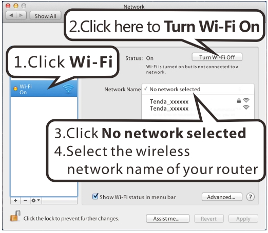
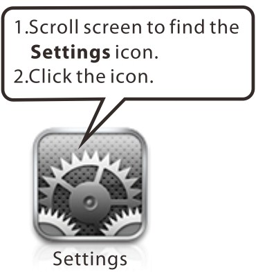
92 iphone/ipad


93 Wireless Modem Router User Guide
94 Appendix 3 FAQs 1. What information should I have to access Internet via the ADSL uplink? If you have DSL broadband service, you might need the following information to set up your modem router. Active Internet service provided by an ADSL account The ISP configuration information for your DSL account - ISP login name and password - Fixed or static IP address Depending on how your ISP set up your Internet account, you could need to know the Virtual path identifier (VPI) and virtual channel identifier (VCI) parameters for a manual setup. 2. I cannot access the device's management interface. What should I do? 1. Verify the physical connection (namely, the Ethernet cable) between your PC and the device. For details, see Hardware Install hereof. 2. Double check the TCP/IP settings on your PC. For details, see Appendix 1.Configure PC hereof. 3. Press the Reset button on the device and then re-access the management interface. 4. Change the Ethernet cable that connects your PC and the device. 5. Try accessing device management interface from other PCs, smart phones or ipads. 6. Connect your PC alone to one of the LAN ports on the device. 3. I forget the wireless security key. What should I do? (How do I configure or change the security key?) 1. Try the default security key, which can be seen from the label attached to the device bottom. 2. If step 1 that works, access the device web manager and customize a new security key. 3. If step 1 does not work, press the Reset button on the device to restore factory default settings. And then log in to the device web manager to customize a new security key. 4. My notebook is unable to search wireless networks, what should I do? 1. Verify that wireless service is enabled on your notebook by checking the wireless hardware or software button on your notebook. The hardware button is usually located on the side of your notebook. Note that some notebooks may not have such hardware button. Software button can be implemented by pressing Fn+ the bottom left corner of your keyboard, keyboard you are using.. Fn is situated on may be any key between F1-F12 depending on what type of 2. Log in to the device, select Advanced-> Wireless-> Basic and change the wireless network name (SSID). Then search again. 3. Follow below steps to verify that wireless service is enabled on your notebook (for Windows XP OS only). From the desktop, right-click on the My Computer icon and select Manage. Select Services and Applications, double click Services and view the status of Wireless Zero Configuration. If Status dose not display Started, right click the Wireless Zero Configuration and select Start; if Startup Type displays Disabled, right click the Wireless Zero Configuration, select Properties; from the Startup Type drop-down list box, select Automatic and then click Start in Service Status. 5. Why cannot I connect to the searched wireless network? 1. Verify that you entered a correct security key. 2. Log in to the device, select Advanced-> Wireless and change the wireless network name (SSID). Then connect again
95 3. Log in to the device, select Advanced-> Wireless-> Security and change the security settings. Then connect again. 6. Where should I place the wireless device for optimum performance? 1. Place it in the center to extend wireless coverage as far as possible. 2. Never place the device near to metal objects or in direct sunshine. 3. Keep it far away from devices that use the 2.4 GHz radio wave frequency to transmit and receive data, such as g/n wireless network devices, electronic devices such as cell phones, radio transmitters, blue tooth, cordless phones, fax machine, refrigerator and microwaves to avoid electronic interference
96 Appendix 4 VPI/VCI List The following table lists common ISPs and their VPI and VCI numbers. If you cannot locate your ISP and their VPI and VCI information here, ask your ISP to provide it. Country ISP VPI VCI Encapsulation Australia Telstra 8 35 PPPoA LLC Australia GoldenIT 8 35 _PPPOA_VCMUX Australia Telstra Bigpond 8 35 PPPOE_LLC Australia OptusNET 8 35 PPPOE_VCMUX Australia AAPT 8 35 PPPOE_VCMUX Australia ADSL Direct 8 35 PPPOE_LLC Australia Ausie Broadband 8 35 PPPOE_LLC Australia Australia On Line 8 35 PPPOA_VCMUX Australia Connexus 8 35 PPPOE_LLC Australia Dodo 8 35 PPPOE_LLC Australia Gotalk 8 35 PPPOE_VCMUX Australia Internode 8 35 PPPOE_VCMUX Australia iprimus 8 35 PPPOA_VCMUX Australia Netspace 8 35 PPPOE_VCMUX Australia Southern Cross Telco 8 35 PPPOE_LLC Australia TPG Internet 8 35 PPPOE_LLC Argentina Telecom 0 33 PPPoE LLC Argentina Telefonica 8 35 PPPoE LLC Argentina 1 33 PPPoA VC-MUX Belgium ADSL Office Routed IP LLC Belgium Turboline 8 35 PPPoA LLC Bolivia Routed IP LLC Brazil Brasil Telcom 0 35 PPPoE LLC Brazil Telefonica 8 35 PPPoE LLC Brazil Telmar 0 33 PPPoE LLC Brazil South Region 1 32 PPPoE LLC Colombia EMCALI 0 33 PPPoA VC-MUX Columbia ETB 0 33 PPPoE LLC Costa Rica ICE Routed IP LLC Denmark Cybercity, Tiscali 0 35 PPPoA VC-MUX France (1) Orange 8 35 PPPoE LLC France (2) 8 67 PPPoE LLC France (3) SFR 8 35 PPPoA VC-MUX Germany 1 32 PPPoE LLC Hungary Sci-Network 0 35 PPPoE LLC Iceland Islandssimi 0 35 PPPoA VC-MUX
97 Wireless Modem Router User Guide Iceland Siminn 8 48 PPPoA VC-MUX Israel 8 35 PPPoA VC-MUX Italy 8 35 PPPoA VC-MUX Iran (1) 0 35 PPPoE LLC Iran (2) 8 81 PPPoE LLC Israel(1) 8 48 PPPoA VC-MUX Jamaica (1) 8 35 PPPoA VC-MUX Jamaica (2) 0 35 PPPoA VC-MUX Jamaica (3) Bridged IP LLC SNAP Jamaica (4) Bridged IP LLC SNAP Kazakhstan 0 33 PPPoA VC-MUX Malaysia 0 35 PPPoE LLC Mexico Telmex (1) 8 81 PPPoE LLC Mexico Telmex (2) 8 35 PPPoE LLC Mexico Telmex (3) 0 81 PPPoE LLC Mexico Telmex (4) 0 35 PPPoE LLC Netherlands BBNED 0 35 PPPoA VC-MUX Netherlands MX Stream 8 48 PPPoA VC-MUX New Zealand Xtra 0 35 PPPoA VC-MUX New Zealand Slingshot PPPoA VC-MUX Pakistan (cyber net) 8 35 PPPoE LLC Pakistan (linkdotnet) 0 35 PPPoA LLC Pakistan(PTCL) 8 81 PPPoE LLc Portugal 0 35 PPPoE LLC Puerto Rico Coqui.net 0 35 PPPoA LLC Saudi Arabia (1) 0 33 PPPoE LLC Saudi Arabia (2) 0 35 PPPoE LLC Saudi Arabia (3) Bridged IP LLC Saudi Arabia (4) Routed IP LLC Saudi Arabia (5) Bridged IP LLC Saudi Arabia (6) Routed IP LLC Spain Albura, Tiscali 1 32 PPPoA VC-MUX Spain Colt Telecom, Ola Internet 0 35 PPPoA VC-MUX Spain EresMas, Retevision 8 35 PPPoA VC-MUX Spain Telefonica (1) 8 32 PPPoE LLC Spain Telefonica (2), Terra Routed IP LLC Spain Wanadoo (1) 8 35 PPPoA VC-MUX Spain Wanadoo (2) 8 32 PPPoE LLC Spain Wanadoo (3) Routed IP LLC Sweden Telenordia 8 35 PPPoE Sweden Telia Routed IP LLC Switzerland 8 35 PPPoE LLC Trinidad & Tobago TSTT 0 35 PPPoA VC-MUX Turkey (1) 8 35 PPPoE LLC
98 Turkey (2) 8 35 PPPoA VC-MUX Thailand TRUE PPPoE LLC Thailand TOT 1 32 PPPoE LLC Thailand 3BB 0 33 PPPoE LLC Thailand Cat Telecom 0 35 PPPoE LLC Thailand BuddyBB 0 35 PPPoE LLC United States 4DV.Net 0 32 PPPoA VC-MUX United States All Tel (1) 0 35 PPPoE LLC United States All Tel (2) Bridged IP LLC United States Ameritech 8 35 PPPoA LLC United States AT&T (1) 0 35 PPPoE LLC United States AT&T (2) Bridged IP LLC United States AT&T (3) Bridged IP LLC United States August.net (1) Bridged IP LLC United States August.net (2) Bridged IP LLC United States BellSouth 8 35 PPPoE LLC United States Casstle.Net Bridged IP LLC United States CenturyTel (1) 8 35 PPPoE LLC United States CenturyTel (2) Bridged IP LLC United States Coqui.net 0 35 PPPoA LLC United States Covad 0 35 PPPoE LLC United States Earthlink (1) 0 35 PPPoE LLC United States Earthlink (2) 8 35 PPPoE LLC United States Earthlink (3) 8 35 PPPoE VC-MUX United States Earthlink (4) 0 32 PPPoA LLC United States Eastex PPPoA LLC United States Embarq Bridged IP LLC United States Frontier 0 35 PPPoE LLC United States Grande ommunications 1 34 PPPoE LLC United States GWI Bridged IP LLC United States Hotwire Bridged IP LLC United States Internet Junction Bridged IP LLC United States PVT Bridged IP LLC United States QWest (1) 0 32 PPPoALLC United States QWest (2) 0 32 PPPoA VC-MUX United States QWest (3) Bridged IP LLC United States QWest (4) 0 32 PPPoE LLC United States SBC (1) 0 35 PPPoE LLC United States SBC (2) Bridged IP LLC United States SBC (3) Bridged IP LLC United States Sonic Bridged IP LLC United States SouthWestern Bell Bridged IP LLC United States Sprint (1) 0 35 PPPoALLC United States Sprint (2) 8 35 PPPoE LLC
99 United States Sprint Territory 0 35 PPPoE LLC Wireless Modem Router User Guide United States SureWest Communications(1) Bridged LLC Snap United States SureWest Communications(2) 0 32 PPPoE LLC United States SureWest Communications(3) 0 32 PPPoA LLC United States Toast.Net 0 35 PPPoE LLC United States Uniserv Bridged IP LLC United States US West 0 32 PPPoA VC-MUX United States Verizon (1) 0 35 PPPoE LLC United States Verizon (2) Bridged IP LLC United States Windstream 0 35 PPPoE LLC Canada Primus Canada 0 35 PPPoE LLC Canada Rogers Canada (1) 0 35 PPPoE LLC Canada Rogers Canada (2) Bridged IP LLC Canada Rogers Canada (3) Bridged IP LLC Canada BellSouth(1) Canada 8 35 PPPoE LLC Canada BellSouth(2) Canada 0 35 PPPoE LLC Canada Sprint (1) Canada 0 35 PPPoA LLC Canada Sprint (2) Canada 8 35 PPPoE LLC Canada Verizon (1) Canada 0 35 PPPoE LLC Canada Verizon (2) Canada Bridged IP LLC United States Verizon (2) Bridged IP LLC United Kingdom (1) 0 38 PPPoA VC-MUX United Kingdom (2) 0 38 PPPoE LLC United Kingdom AOL 0 38 PPPoE VC-MUX United Kingdom Karoo 1 50 PPPoA LLC Venezuela CANTV Routed IP LLC Vietnam 0 35 PPPoE LLC Vietnam VDC 8 35 PPPoE LLC Vietnam Viettel 8 35 PPPoE LLC Vietnam FPT 0 33 PPPoE LLC Russia Rostel 0 35 PPPoE LLC Russia Port telecom 0 35 PPPoE LLC Russia VNTC 8 35 PPPoE LLC Uzbekistan Sharq Stream 8 35 PPPoE LLC Uzbekistan Sarkor 0 33 PPPoE LLC Uzbekistan TShTT 0 35 PPPoE LLC Kazakhstan Kazakhtelecom «Megaline» 0 40 LLC/SNAP Bridging Spain Arrakis Bridged IP VC-MUX Spain Auna Bridged IP VC-MUX Spain Comunitel Bridged IP VC-MUX
100 Wireless Modem Router User Guide Spain Eresmas Bridged IP VC-MUX Spain Jazztel 8 35 IPOE VC-MUX Spain Jazztel ADSL2+ / Desagregado Bridged IP LLC-BRIDGING Spain OpenforYou Bridged IP VC-MUX Spain Tele Bridged IP VC-MUX Spain Telefónica (España) Bridged IP LLC/SNAP Telefónica (Argentina) Bridged IP LLC-based Telefónica (Perú) Bridged IP VC-MUX Spain Terra Bridged IP LLC/SNAP Spain Terra Bridged IP LLC/SNAP Spain Uni Bridged IP VC-MUX Spain Orange Bridged IP VC-MUX Spain Orange 20 Megas 8 35 LLC-BRIDGING Spain Orange Bridged IP LLC/SNAP Spain Ya.com Bridged IP VC - MUX Spain Ya.com Bridged IP LLC/SNAP France Free 8 36 LLC Netherlands MXSTREAM Bridged IP LLC Netherlands BBNED Bridged IP LLC Belgium Turboline Bridged IP LLC Belgium ADSL Office Bridged IP LLC UK Bridged IP LLC Italy Bridged IP LLC Switzerland Bridged IP LLC SpainWanadoo Bridged IP LLC Czech Republic Bridged IP LLC Dubai Bridged IP LLC UAE (Al sahmil) Bridged IP LLC Egypt: TE-data Bridged IP LLC Egypt: Linkdsl Bridged IP LLC Egypt: Vodafone Bridged IP LLC kuwait unitednetwork Bridged IP LLC Pakistan (PALESTINE) Bridged IP LLC Dominican Republic Bridged IP LLC Orange Nyumbani (Kenya) 0 35 PPPoE LLC Pakistan for PTCL Bridged IP LLC Sri Lanka Telecom-(SLT) 8 35 PPPOE LLC Philippines(1) Bridged IP LLC Philippines(2) Bridged IP LLC RomTelecom Romania: Bridged IP LLC
101 Finland Saunalahti Bridged IP LLC Finland Elisa Bridged IP LLC Finland DNA Bridged IP LLC Finland Sonera Bridged IP LLC Iran [Shatel] Aria-Rasaneh-Tadbir 0 35 PPPOE LLC Iran Asia-Tech 0 35 PPPOE LLC Iran Pars-Online (Tehran) 0 35 PPPOE LLC Iran Pars-Online (Provinces) 0 59 PPPOE LLC Iran [Saba-Net] Neda-Gostar-Saba 0 35 PPPOE LLC Iran Pishgaman-Tose 0 35 PPPOE LLC Iran Fan-Ava 8 35 PPPOE LLC Iran Datak 0 35 PPPOE LLC Iran Laser (General) 0 35 PPPOE LLC Iran Laser (Privates) 0 32 PPPOE LLC Iran Asr-Enteghal-Dadeha 8 35 PPPOE LLC Iran Kara-Amin-Ertebat 0 33 PPPOE LLC Iran ITC 0 35 PPPOE LLC Iran Dadegostar Asre Novin 0 33 PPPOE LLC India Airtel Bridged IP LLC India BSNL Bridged IP LLC India MTNL Bridged IP LLC India RELIANCE COMMUNICATION 0 35 PPPOE LLC India TATA INDICOM 0 32 PPPOE LLC India CONNECT 1 32 PPPOE LLC morocco IAM 8 35 PPPOE Malaysia Streamyx 0 35 PPPOE LLC Indonesia Speedy Telkomnet 8 81 PPPoE LLC
102 Appendix 5 Regulatory Compliance Information CE Mark Warning This is a Class B product In a domestic environment,this product may cause radio interference,in which case the user may be required to take adequate measures.this device complies with EU 1999/5/EC. NOTE:(1)The manufacturer is not responsible for any radio or TV interference caused by unauthorized modifications to this equipment.(2) To avoid unnecessary radiation interference, it is recommended to use a shielded RJ45 cable FCC Statement This device complies with Part 15 of the FCC Rules. Operation is subject to the following two conditions: (1) This device may not cause harmful interference, and (2) this device must accept any interference received, including interference that may cause undesired operation. This equipment has been tested and found to comply with the limits for a Class B digital device, pursuant to Part 15 of the FCC Rules. These limits are designed to provide reasonable protection against harmful interference in a residential installation. This equipment generates, uses and can radiate radio frequency energy and, if not installed and used in accordance with the instructions, may cause harmful interference to radio communications. However, there is no guarantee that interference will not occur in a particular installation. If this equipment does cause harmful interference to radio or television reception, which can be determined by turning the equipment off and on, the user is encouraged to try to correct the interference by one of the following measures: Reorient or relocate the receiving antenna. Increase the separation between the equipment and receiver. Connect the equipment into an outlet on a circuit different from that to which the receiver is connected. Consult the dealer or an experienced radio/tv technician for help. FCC Caution: Any changes or modifications not expressly approved by the party responsible for compliance could void the user's authority to operate this equipment
103 This transmitter must not be co-located or operating in conjunction with any other antenna or transmitter. The manufacturer is not responsible for any radio or TV interference caused by unauthorized modifications to this equipment. Radiation Exposure Statement This equipment complies with FCC radiation exposure limits set forth for an uncontrolled environment. This equipment should be installed and operated with minimum distance 20cm between the radiator & your body. NOTE: (1)The manufacturer is not responsible for any radio or TV interference caused by unauthorized modifications to this equipment.(2) To avoid unnecessary radiation interference, it is recommended to use a shielded RJ45 cable
ADSL2/2+ Wireless-N Router 150Mbps plus
 ADSL2/2+ Wireless-N Router 150Mbps plus User s Manual Cod. KN.2R Warning The manufacturer is under no circumstances liable for any unauthorised modifications made to the product by the user or any other
DSL-2600U. User Manual V 1.0
 DSL-2600U User Manual V 1.0 CONTENTS 1. OVERVIEW...3 1.1 ABOUT ADSL...3 1.2 ABOUT ADSL2/2+...3 1.3 FEATURES...3 2 SPECIFICATION...4 2.1 INDICATOR AND INTERFACE...4 2.2 HARDWARE CONNECTION...4 2.3 LED STATUS
Chapter 3 Connecting the Router to the Internet
 Chapter 3 Connecting the Router to the Internet This chapter describes how to set up the router on your Local Area Network (LAN) and connect to the Internet. It describes how to configure your DG834GT
Table of Contents. D-Link DSL-2730U User Manual 1
 Table of Contents D-Link DSL-2730U User Manual 1 Table of Contents PACKAGE CONTENTS... 4 SYSTEM REQUIREMENTS... 4 FEATURES... 5 HARDWARE OVERVIEW... 7 Connections... 7 LEDs... 8 INSTALLATION... 9 BEFORE
RedRapid X WIRELESS MODEM ROUTER. Quick Installation Guide (DN-7060)
") RedRapid X WIRELESS MODEM ROUTER Quick Installation Guide (DN-7060) 1. Product Introduction Congratulations on purchasing this Wireless N ADSL2/2+ Router. This router is a cost-effective ADSL2+ router,
RedRapid X WIRELESS MODEM ROUTER Quick Installation Guide (DN-7060) 1. Product Introduction Congratulations on purchasing this Wireless N ADSL2/2+ Router. This router is a cost-effective ADSL2+ router,
Overview. Introduction
 Table of Contents Manual... 1 Overview... 3 Introduction... 3 Package Contents... 4 System Requirements... 4 Hardware Overview... 5 Rear Panel... 5 Front Pannel... 6 Features... 7 Configuration... 8 Log
ADSL MODEM. User Manual V1.0
 ADSL MODEM User Manual V1.0 CONTENTS 1.OVERVIEW... 3 1.1 ABOUT ADSL... 3 1.2 ABOUT ADSL2/2+... 3 1.3 FEATURES... 3 2 SPECIFICATION... 4 2.1 INTERFACE INTRODUCTION... 4 2.1.1 INDICATOR AND INTERFACE...
Broadband ADSL2+ Modem DM111PSPv2
 Broadband ADSL2+ Modem DM111PSPv2 User Manual 350 East Plumeria Drive San Jose, CA 95134 USA August 2011 202-10913-01 v1.0 2011 NETGEAR, Inc. All rights reserved No part of this publication may be reproduced,
BROADBAND INTERNET ROUTER USER S MANUAL. Version 1.0. - Page 1 of 13 -
 Version 1.0 - Page 1 of 13 - 10/100M Broadband Router GETTING TO KNOW 2 3 4 1 5 7 6 - Page 2 of 13 - LED Indicator S/N Indicator Function 1 Power LED (Green) LED lights up steadily indicate that the power
Multifunctional Broadband Router User Guide. Copyright Statement
 Copyright Statement is the registered trademark of Shenzhen Tenda Technology Co., Ltd. Other trademark or trade name mentioned herein are the trademark or registered trademark of above company. Copyright
N150 WiFi Router (N150R)
") Easy, Reliable & Secure N150 WiFi Router (N150R) User Manual 350 East Plumeria Drive San Jose, CA 95134 USA August 2012 202-11000-01 v1.0 Trademarks Brand and product names are trademarks or registered
Easy, Reliable & Secure N150 WiFi Router (N150R) User Manual 350 East Plumeria Drive San Jose, CA 95134 USA August 2012 202-11000-01 v1.0 Trademarks Brand and product names are trademarks or registered
Ovislink OV504WN User Manual. Ver 1.0
 Ovislink OV504WN User Manual Ver 1.0 Contents 1 Safety Precautions... 1 2 Overview... 2 2.1 Application... 2 2.2 Features... 2 2.3 Standards Compatibility and Compliance... 3 3 Hardware Description and
NOTICE. All brand and product names are the trademarks of their respective owners. Copyright 2011 All rights reserved.
 X7N USER MANUAL NOTICE This document contains proprietary information protected by copyright, and this Manual and all the accompanying hardware, software, and documentation are copyrighted. No part of
MN-700 Base Station Configuration Guide
 MN-700 Base Station Configuration Guide Contents pen the Base Station Management Tool...3 Log ff the Base Station Management Tool...3 Navigate the Base Station Management Tool...4 Current Base Station
INSTALLATION... 6 DIAGNOSTICS...
 Table of Contents Table of Contents PACKAGE CONTENTS... 2 QUALITY OF SERVICE... 41 SYSTEM REQUIREMENTS... 2 Queue Config... 41 FEATURES... 3 QoS Classification... 42 HARDWARE OVERVIEW... 4 ROUTING... 43
Chapter 4 Customizing Your Network Settings
 . Chapter 4 Customizing Your Network Settings This chapter describes how to configure advanced networking features of the Wireless-G Router Model WGR614v9, including LAN, WAN, and routing settings. It
Wireless Router Setup Manual
 Wireless Router Setup Manual NETGEAR, Inc. 4500 Great America Parkway Santa Clara, CA 95054 USA 208-10082-02 2006-04 2006 by NETGEAR, Inc. All rights reserved. Trademarks NETGEAR is a trademark of Netgear,
Chapter 1 Connecting Your Router to the Internet
 Chapter 1 Connecting Your Router to the Internet This chapter describes how to configure your DG834N RangeMax TM NEXT Wireless ADSL2+ Modem Router Internet connection.when you perform the initial configuration
-1 - ADSL2/2+ Router
 -1 - ADSL2/2+ Router Copyright Statement is the registered trademark of Shenzhen Tenda Technology Co., Ltd. All the products and product names mentioned herein are the trademarks or registered trademarks
Protecting the Home Network (Firewall)
") Protecting the Home Network (Firewall) Basic Tab Setup Tab DHCP Tab Advanced Tab Options Tab Port Forwarding Tab Port Triggers Tab DMZ Host Tab Firewall Tab Event Log Tab Status Tab Software Tab Connection
Protecting the Home Network (Firewall) Basic Tab Setup Tab DHCP Tab Advanced Tab Options Tab Port Forwarding Tab Port Triggers Tab DMZ Host Tab Firewall Tab Event Log Tab Status Tab Software Tab Connection
Broadband Phone Gateway BPG510 Technical Users Guide
 Broadband Phone Gateway BPG510 Technical Users Guide (Firmware version 0.14.1 and later) Revision 1.0 2006, 8x8 Inc. Table of Contents About your Broadband Phone Gateway (BPG510)... 4 Opening the BPG510's
C2-010/C2-010-I ADSL2+ Router
 s C2-010/C2-010-I ADSL2+ Router User s Manual Rev: 1.3 2005/1210 No part of this publication may be reproduced in any form by any means without the prior written permission. Other trademarks or brand names
your Gateway Windows network installationguide 802.11b wireless series Router model WBR-100 Configuring Installing
 your Gateway Windows network installationguide 802.11b wireless series Router model WBR-100 Installing Configuring Contents 1 Introduction...................................................... 1 Features...........................................................
Comtrend 1 Port Router Installation Guide CT-5072T
 Comtrend 1 Port Router Installation Guide CT-5072T 1 Installing Access Point s DSL Service with a Comtrend Router Thank you for selecting Access Point, Inc. to be your Internet service provider. This guide
A Division of Cisco Systems, Inc. Broadband Router. with 2 Phone Ports. Voice Installation and Troubleshooting Guide RTP300. Model No.
 A Division of Cisco Systems, Inc. Broadband Router with 2 Phone Ports Voice Installation and Troubleshooting Guide Model No. RTP300 Copyright and Trademarks Specifications are subject to change without
AMG1312-T Series. User s Guide. Quick Start Guide. Wireless N ADSL2+ 4-port Gateway with USB. Default Login Details. Version 2.00 Edition 1, 8/2013
 AMG1312-T Series Wireless N ADSL2+ 4-port Gateway with USB Version 2.00 Edition 1, 8/2013 Quick Start Guide User s Guide Default Login Details LAN IP Address http://192.168.1.1 User Name admin Passwordwww.zyxel.com
Voice Gateway with Router
 Voice User Guide Model No. SPA3102 Copyright and Trademarks Specifications are subject to change without notice. Linksys is a registered trademark or trademark of Cisco Systems, Inc. and/or its affiliates
BR-6104K / BR-6104KP Fast Ethernet Broadband Router User s Manual
 BR-6104K / BR-6104KP Fast Ethernet Broadband Router User s Manual 1 Introduction... 4 Features... 4 Minimum Requirements... 4 Package Content... 4 Note... 4 Get to know the Broadband Router... 4 Back Panel...
TW100-BRF114 Firewall Router. User's Guide. Cable/DSL Internet Access. 4-Port Switching Hub
 TW100-BRF114 Firewall Router Cable/DSL Internet Access 4-Port Switching Hub User's Guide Table of Contents CHAPTER 1 INTRODUCTION...1 TW100-BRF114 Features...1 Package Contents...3 Physical Details...
FG7008GR(AC) DUAL BAND WIRELESS-AC MU-MIMO GIGABIT ROUTER
 DUAL BAND WIRELESS-AC MU-MIMO GIGABIT ROUTER") FG7008GR(AC) DUAL BAND WIRELESS-AC MU-MIMO GIGABIT ROUTER Page 2 of 88 Copyright 2014 All rights reserved. No part of this document may be reproduced, republished, or retransmitted in any form or by any
FG7008GR(AC) DUAL BAND WIRELESS-AC MU-MIMO GIGABIT ROUTER Page 2 of 88 Copyright 2014 All rights reserved. No part of this document may be reproduced, republished, or retransmitted in any form or by any
DSL-G604T Install Guides
 Internet connection with NAT...2 Internet connection with No NAT, IP Un-number...6 Port Forwarding...12 Filtering & Firewall Setup...20 Access Control... 21 DMZ Setup... 26 Allow Incoming Ping... 27 How
AMG1302-TSeries. AMG1202-TSeries. User s Guide. Quick Start Guide. Wireless N ADSL2+ 4-port Gateway. Wireless N-lite ADSL2+ 4-port Gateway
 AMG1302-TSeries Wireless N ADSL2+ 4-port Gateway AMG1202-TSeries Wireless N-lite ADSL2+ 4-port Gateway Version 2.00(AAJC.0) Edition 2, 5/2013 Quick Start Guide User s Guide Default Login Details LAN IP
Quick Installation Guide DSL-2750U/NRU. 3G/ADSL/Ethernet Router with Wi-Fi and Built-in Switch
 DSL-2750U/NRU 3G/ADSL/Ethernet Router with Wi-Fi and Built-in Switch BEFORE YOU BEGIN Delivery Package Router DSL-2750U/NRU Power adapter RJ-11 telephone cable Straight-through Ethernet cable (CAT 5E)
Wireless DSL Gateway GT704WG. User s Manual
 Wireless DSL Gateway GT704WG User s Manual Table of Contents 1 Introduction 1 Minimum System Requirements 1 Features 2 Getting to Know the Gateway 3 2 Performing a Quick Setup 7 Accessing Quick Setup Screens
Broadband Router ESG-103. User s Guide
 Broadband Router ESG-103 User s Guide FCC Warning This equipment has been tested and found to comply with the limits for Class A & Class B digital device, pursuant to Part 15 of the FCC rules. These limits
UIP1868P User Interface Guide
 UIP1868P User Interface Guide (Firmware version 0.13.4 and later) V1.1 Monday, July 8, 2005 Table of Contents Opening the UIP1868P's Configuration Utility... 3 Connecting to Your Broadband Modem... 4 Setting
TD-W8960N Wireless N ADSL2+ Modem Router
 Wireless N ADSL2+ Modem Router Rev: 1.0.0 1910010174 COPYRIGHT & TRADEMARKS Specifications are subject to change without notice. is a registered trademark of TP-LINK TECHNOLOGIES CO., LTD. Other brands
Front LEDs... 2 Rear Ports... 3 BASIC INSTALLATION... 4 Connecting Your Router... 5 Network Configuration... 6
 0 P a g e Table of contents Front LEDs... 2 Rear Ports... 3 BASIC INSTALLATION... 4 Connecting Your Router... 5 Network Configuration... 6 Gateway Configuration... 11 Accessing your gateway... 11 Displaying
Table of Contents. D-Link DSL-2640U User Manual 1
 Table of Contents D-Link DSL-2640U User Manual 1 Table of Contents PACKAGE CONTENTS... 4 SYSTEM REQUIREMENTS... 4 FEATURES... 5 HARDWARE OVERVIEW... 7 Connections... 7 LEDs... 8 INSTALLATION... 9 BEFORE
Internet and Intranet Calling with Polycom PVX 8.0.1
 Internet and Intranet Calling with Polycom PVX 8.0.1 An Application Note Polycom PVX is an advanced conferencing software application that delivers Polycom's premium quality audio, video, and content sharing
User Manual DIR-632. Multifunction Wireless Router Supporting WiMAX, 3G GSM/CDMA with Built-in 8-port Switch
 DIR-632 Multifunction Wireless Router Supporting WiMAX, 3G GSM/CDMA with Built-in 8-port Switch October 2011 Contents Chapter 1. Introduction...5 Contents and Audience...5 Conventions...5 Document Structure...5
User Manual. Page 2 of 38
 DSL1215FUN(L) Page 2 of 38 Contents About the Device...4 Minimum System Requirements...5 Package Contents...5 Device Overview...6 Front Panel...6 Side Panel...6 Back Panel...7 Hardware Setup Diagram...8
N300 Wireless ADSL2+ Modem Router DGN2200M Mobile Edition
 N300 Wireless ADSL2+ Modem Router DGN2200M Mobile Edition User Manual 350 East Plumeria Drive San Jose, CA 95134 USA November 2011 202-10604-02 v1.0 2011 NETGEAR, Inc. All rights reserved No part of this
Preface. Manual Revisions. Trademarks
 Preface D-Link reserves the right to revise this publication and to make changes in the content hereof without obligation to notify any person or organization of such revisions or changes. Manual Revisions
TL-R460 Cable/DSL Router
 Cable/DSL Router Rev: 2.0.0 1910010471 COPYRIGHT & TRADEMARKS Specifications are subject to change without notice. is a registered trademark of TP-LINK TECHNOLOGIES CO., LTD. Other brands and product names
Broadband Router ALL1294B
 Broadband Router ALL1294B Broadband Internet Access 4-Port Switching Hub User's Guide Table of Contents CHAPTER 1 INTRODUCTION... 1 Broadband Router Features... 1 Package Contents... 3 Physical Details...
TW100-BRV204 VPN Firewall Router
 TW100-BRV204 VPN Firewall Router Cable/DSL Internet Access 4-Port Switching Hub User's Guide Table of Contents CHAPTER 1 INTRODUCTION... 1 TW100-BRV204 Features... 1 Package Contents... 3 Physical Details...
WiFi Cable Modem Router C3700
 User Manual Note: This document is for certification purposes only. Images are for position only and might differ from the actual product. October 2013 350 East Plumeria Drive San Jose, CA 95134 USA Support
High Speed. Internet BroadBand Router. User Guide
 High Speed Internet BroadBand Router User Guide FCC Warning This equipment has been tested and found to comply with the regulations for a Class B digital device, pursuant to Part 15 of the FCC Rules. These
High Speed. Internet BroadBand Router. User Guide
 High Speed Internet BroadBand Router User Guide FCC Warning This equipment has been tested and found to comply with the regulations for a Class B digital device, pursuant to Part 15 of the FCC Rules.
AMG1001-T Series. AMG1011-T Series. User s Guide. Quick Start Guide. ADSL2+ 1-port Gateway. ADSL2+ 1-port Ethernet/USB Gateway. Default Login Details
 AMG1001-T Series ADSL2+ 1-port Gateway AMG1011-T Series ADSL2+ 1-port Ethernet/USB Gateway Version 1.00 Edition 1, 07/2013 Quick Start Guide User s Guide Default Login Details IP Address http://192.168.1.1
Load Balancer LB-2. User s Guide
 Load Balancer LB-2 User s Guide TABLE OF CONTENTS 1: INTRODUCTION...1 Internet Features...1 Other Features...3 Package Contents...4 Physical Details...4 2: BASIC SETUP...8 Overview...8 Procedure...8 3:
DSL-2500U. D-Link. User Manual. ADSL2/2+ Ethernet Router. RECYCLABLE 2006/08/30 Ver. 1.00. Building Networks for People
 D-Link DSL-2500U ADSL2/2+ Ethernet Router User Manual Building Networks for People RECYCLABLE 2006/08/30 Ver. 1.00 Table of Contents GENERAL INFORMATION... 3 Package Contents... 3 Important Safety Instructions...
Load Balancing Router. User s Guide
 Load Balancing Router User s Guide TABLE OF CONTENTS 1: INTRODUCTION... 1 Internet Features... 1 Other Features... 3 Package Contents... 4 Physical Details... 4 2: BASIC SETUP... 8 Overview... 8 Procedure...
300Mbps Wireless N VoIP VDSL/ADSL Modem Router
 300Mbps Wireless N VoIP VDSL/ADSL Modem Router TD-VG5612 Highlights Fast Broadband Speeds Up to 100Mbps broadband speeds, ideal for smooth streaming media and online gaming Cost-Effective VoIP Supports
Wireless Cable Gateway CG3100Dv3
 Wireless Cable Gateway CG3100Dv3 User Manual 350 East Plumeria Drive San Jose, CA 95134 USA October 2011 202-10942-01 v1.0 2011 NETGEAR, Inc. All rights reserved No part of this publication may be reproduced,
Chapter 4 Customizing Your Network Settings
 Chapter 4 Customizing Your Network Settings This chapter describes how to configure advanced networking features of the RangeMax Dual Band Wireless-N Router WNDR3300, including LAN, WAN, and routing settings.
TD-W8960N 300Mbps Wireless N ADSL2+ Modem Router
 TD-W8960N 300Mbps Wireless N ADSL2+ Modem Router Rev: 4.0.0 1910010506 COPYRIGHT & TRADEMARKS Specifications are subject to change without notice. is a registered trademark of TP-LINK TECHNOLOGIES CO.,
VDSL2/GigE Wireless 11n Gateway. Model #: T1200H, T2200H. User Manual. Ver 1.0. Solutions for the Digital Life
 VDSL2/GigE Wireless 11n Gateway Model #: T1200H, T2200H User Manual Ver 1.0 Solutions for the Digital Life Table of Contents Introduction 1 Minimum System Requirements 1 Features 2 Getting to Know the
BR-6624. Load Balancing Router. Manual
 BR-6624 Load Balancing Router Manual TABLE OF CONTENTS 1: INTRODUCTION...1 Internet Features...1 Other Features...3 Package Contents...4 Physical Details...4 2: BASIC SETUP...8 Overview...8 Procedure...8
Wireless G Broadband quick install
 Wireless G Broadband Router quick install guide Model 503693 INT-503693-QIG-0608-02 Thank you for purchasing the INTELLINET NETWORK SOLUTIONS Wireless G Broadband Router, Model 503693. This quick install
Table of Contents. D-Link DSL-2750U User Manual 1
 Table of Contents D-Link DSL-2750U User Manual 1 Table of Contents PACKAGE CONTENTS... 4 SYSTEM REQUIREMENTS... 4 FEATURES... 5 HARDWARE OVERVIEW... 7 Connections... 7 LEDs... 8 INSTALLATION... 9 BEFORE
Downloaded from www.manualslib.com manuals search engine
 Copyright and Trademarks Specifications are subject to change without notice. Linksys is a registered trademark or trademark of Cisco Systems, Inc. and/or its affiliates in the U.S. and certain other countries.
Multi-Homing Security Gateway
 Multi-Homing Security Gateway MH-5000 Quick Installation Guide 1 Before You Begin It s best to use a computer with an Ethernet adapter for configuring the MH-5000. The default IP address for the MH-5000
N300 WiFi ADSL2+ Modem Router (N300RM)
") Easy, Reliable & Secure N300 WiFi ADSL2+ Modem Router (N300RM) User Manual 350 East Plumeria Drive San Jose, CA 95134 USA December 2012 202-11208-01 v1.0 Trademarks Brand and product names are trademarks
Easy, Reliable & Secure N300 WiFi ADSL2+ Modem Router (N300RM) User Manual 350 East Plumeria Drive San Jose, CA 95134 USA December 2012 202-11208-01 v1.0 Trademarks Brand and product names are trademarks
Wireless Cable Gateway CG3300CMR
 Wireless Cable Gateway CG3300CMR User Manual 350 East Plumeria Drive San Jose, CA 95134 USA September 2012 202-11068-02 v1.0 2012 NETGEAR, Inc. All rights reserved. No part of this publication may be reproduced,
LevelOne. User Manual. FBR-1430 VPN Broadband Router, 1W 4L V1.0
 LevelOne FBR-1430 VPN Broadband Router, 1W 4L User Manual V1.0 Table of Contents CHAPTER 1 INTRODUCTION... 1 VPN BROADBAND ROUTER FEATURES... 1 Internet Access Features... 1 Advanced Internet Functions...
This page displays the device information, such as Product type, Device ID, Hardware version, and Software version.
 Huawei HG622 -- HUAWEI Home Gateway STATUS Device Device xtm WAN LAN WLAN This page displays the device information, such as Product type, Device ID, Hardware version, and Software version. XTM This page
Broadband Router User s Manual
 Broadband Router User s Manual Table of Contents Chapter 1 Introduction...4 1.1 The Broadband Router......4 1.2 Physical Features of Broadband Router...4 1.3 Non-Physical Features of Broadband Router..
Wireless Broadband Router. Manual
 Wireless Broadband Router Manual 1 Introduction... 4 Features... 4 Minimum Requirements... 4 Package Content... 4 Note... 4 Get to know the Broadband Router... 5 Back Panel... 5 Front Panel... 6 Setup
Quidway W1000 Series Wireless Access Device WA1003A Wireless ADSL Access Point User Manual
 Quidway W1000 Series Wireless Access Device WA1003A Wireless ADSL Access Point User Manual HUAWEI Quidway W1000 Series Wireless Access Device WA1003A Wireless ADSL Access Point User Manual Quidway W1000
AC 750. Wireless Dual Band ADSL2+ Modem Router. Highlights
 AC 750 Wireless Dual Band ADSL2+ Modem Router Highlights 750Mbps Wireless Speed 300Mbps on 2.4GHz + 433Mbps on 5GHz Broad Coverage 2 external antennas provide maximum omni-directional wireless coverage
Chapter 1 Configuring Internet Connectivity
 Chapter 1 Configuring Internet Connectivity This chapter describes the settings for your Internet connection and your wireless local area network (LAN) connection. When you perform the initial configuration
Basic IPv6 WAN and LAN Configuration
 Basic IPv6 WAN and LAN Configuration This quick start guide provides basic IPv6 WAN and LAN configuration information for the ProSafe Wireless-N 8-Port Gigabit VPN Firewall FVS318N. For complete IPv6 configuration
Nokia Siemens Networks. CPEi-lte 7212. User Manual
 Nokia Siemens Networks CPEi-lte 7212 User Manual Contents Chapter 1: CPEi-lte 7212 User Guide Overview... 1-1 Powerful Features in a Single Unit... 1-2 Front of the CPEi-lte 7212... 1-2 Back of the CPEi-lte
P-2302HWUDL-P1. Quick Start Guide. 802.11g Wireless VoIP Station Gateway. with Built-in DECT Base Station
 P-2302HWUDL-P1 802.11g Wireless VoIP Station Gateway with Built-in DECT Base Station Quick Start Guide Version 3.60 Edition 1 3/2007 Overview The P-2302HWUDL-P1 model is a router with IEEE 802.11g wireless
ZXDSL 931WII. Maintenance Management Manual. VDSL2 Modem. Version: 3.1
 ZXDSL 931WII VDSL2 Modem Maintenance Management Manual Version: 3.1 ZTE CORPORATION NO. 55, Hi-tech Road South, ShenZhen, P.R.China Postcode: 518057 Tel: +86-755-26771900 Fax: +86-755-26770801 URL: http://ensupport.zte.com.cn
D-Link DSL-2760U USER S MANUAL
 1 TABLE OF CONTENTS... 2 ABOUT THIS USER S GUIDE... 4 INTRODUCTION... 4 PACKAGE CONTENTS... 5 SYSTEM REQUIREMENTS... 5 FEATURES AND BENEFITS... 6 HARDWARE OVERVIEW... 7 FRONT VIEW... 7 REAR VIEW (CONNECTIONS)...
DSL Modem. User Manual. Solutions for the Digital Life. Model #: GT701D. Ver 1.0
 DSL Modem Model #: GT701D User Manual Ver 1.0 Solutions for the Digital Life Table of Contents 1 Introduction 1 Minimum System Requirements 1 Features 2 Getting to Know the Modem 3 2 Performing a Quick
Table of Contents. D-Link DSL-2750U User Manual 1
 Table of Contents D-Link DSL-2750U User Manual 1 Table of Contents TABLE OF CONTENTS... 2 PACKAGE CONTENTS... 4 SYSTEM REQUIREMENTS... 4 FEATURES... 5 HARDWARE OVERVIEW... 7 Connections... 7 LEDs... 8
TL-R402M Cable/DSL Router
 Cable/DSL Router Rev: 3.0.2 1910010053 COPYRIGHT & TRADEMARKS Specifications are subject to change without notice. is a registered trademark of TP-LINK TECHNOLOGIES CO., LTD. Other brands and product names
Firewall VPN Router. Quick Installation Guide M73-APO09-380
 Firewall VPN Router Quick Installation Guide M73-APO09-380 Firewall VPN Router Overview The Firewall VPN Router provides three 10/100Mbit Ethernet network interface ports which are the Internal/LAN, External/WAN,
LW310V2 Sweex Wireless 300N Router
 LW310V2 Sweex Wireless 300N Router Please notice! On the included CD-ROM you will find the Setup Wizard. This easy install procedure will show you how to setup the router step-by-step. Do not expose the
Prestige 623R-T. Quick Start Guide. ADSL Dual-link Router. Version 3.40
 Prestige 623R-T ADSL Dual-link Router Quick Start Guide Version 3.40 February 2004 Introducing the Prestige The Prestige 623R-T ADSL Dual-link Router is the ideal all-in-one device for small networks connecting
Linksys Gateway SPA2100-SU Manual
 Linksys Gateway SPA2100-SU Manual Manuel de l'utilisateur Table of Contents Looking for Basic Setup Instructions?... 3 Most Recent Version of this Manual... 3 Advanced Setup Instructions... 4 Wiring Your
High Speed Internet DSL Modem GT701C. User s Manual
 High Speed Internet DSL Modem GT701C User s Manual Table of Contents 1 Introduction 1 Minimum System Requirements 1 Features 2 Getting to Know the Modem 3 2 Performing a Quick Setup 7 Accessing Quick Setup
CPEi 800/825 Series. User Manual. * Please see the Introduction Section
 CPEi 800/825 Series User Manual * Please see the Introduction Section Contents Introduction...iii Chapter 1: CPEi 800/825 User Guide Overview... 1-1 Powerful Features in a Single Unit... 1-2 Front of the
AC 1200. Wireless Dual Band ADSL2+ Modem Router. Highlights
 AC 1200 Wireless Dual Band ADSL2+ Modem Router Highlights 1200Mbps Wireless Speed 300Mbps on 2.4GHz + 867Mbps on 5GHz Broad Coverage Two external antennas provide maximum omni-directional wireless coverage
N150 Wireless ADSL2+ Modem Router N150RM
 Easy, Reliable & Secure N150 Wireless ADSL2+ Modem Router N150RM User Manual 350 East Plumeria Drive San Jose, CA 95134 USA December 2012 202-11139-01 v1.0 N150 WiFi Router (N150R) Trademarks Brand and
Azatel Communications Inc. 2-Port Multi-Protocol VOIP Gateway Device Administrator Guide
 Azatel Communications Inc. 2-Port Multi-Protocol VOIP Gateway Device Administrator Guide Version 1.5.6 Administrator Guide Azatel VOIP Gateway Copyright Notice All rights reserved, Azatel Communications
English version. LW320/LW321 Sweex Wireless 300N Router. Package Contents. Terminology list
 LW320/LW321 Sweex Wireless 300N Router Do not expose the Sweex Wireless 300N Router to extreme temperatures. Do not place the device in direct sunlight or in the direct vicinity of heating elements. Do
GHz 2.4 802.11g. Wireless-G. User Guide. ADSL Gateway with 2 Phone Ports WIRELESS WAG54GP2. Model No.
 GHz 2.4 802.11g WIRELESS Wireless-G ADSL Gateway with 2 Phone Ports User Guide Model No. WAG54GP2 Copyright and Trademarks Specifications are subject to change without notice. Linksys is a registered trademark
Linksys SPA2102 Router Configuration Guide
 Linksys SPA2102 Router Configuration Guide Dear 8x8 Virtual Office Customer, This Linksys guide provides instructions on how to configure the Linksys SPA2102 as a router. You only need to configure your
P-660R-TxC Series. ADSL2+ Access Router. Quick Start Guide
 P-660R-TxC Series ADSL2+ Access Router Quick Start Guide Version 3.40 Edition 1 2/2006 Overview The P-660R-TxC ADSL2+ access router is the ideal device for small networks connecting to the Internet via
DSL-584T ADSL2+ Router User Guide
 DSL-584T ADSL2+ Router User Guide January 2006 ESL584TEU.A1G FCC Warning This device complies with part 15 of the FCC Rules. Operation is subject to the following two conditions: (1) This device may not
Table of Contents. Wireless Installation Considerations... 10
 Table of Contents Table of Contents Product Overview...4 Package Contents...4 System Requirements... 4 Introduction...5 Features... 6 Hardware Overview...7 Connections... 7 LEDs... 8 Wireless Installation
TL-R480T+ Load Balance Broadband Router
 TL-R480T+ Load Balance Broadband Router Rev: 5.0.0 1910010619 COPYRIGHT & TRADEMARKS Specifications are subject to change without notice. is a registered trademark of TP-LINK TECHNOLOGIES CO., LTD. Other
Prestige 202H Plus. Quick Start Guide. ISDN Internet Access Router. Version 3.40 12/2004
 Prestige 202H Plus ISDN Internet Access Router Quick Start Guide Version 3.40 12/2004 Table of Contents 1 Introducing the Prestige...3 2 Hardware Installation...4 2.1 Rear Panel...4 2.2 The Front Panel
Please use only wired network connections to configure the Router.
 Note Please use only wired network connections to configure the Router. Power down all of your network devices, including your computer(s) and the Modem Router. If you currently use a modem, disconnect
Chapter 1 Installing the Gateway
 Chapter 1 Installing the Gateway This chapter describes how to set up the wireless voice gateway on your Local Area Network (LAN), connect to the Internet, and perform basic configuration. For information