PRESTRESSED CONCRETE POLES The Solid Alternative to Wood
|
|
|
- Leonard Sutton
- 8 years ago
- Views:
Transcription
1 Prestressed Concrete Utility Poles U-1 PRESTRESSED CONCRETE S The Solid Alternative to Wood Lonestar Prestress concrete poles were developed to meet the expanding need of a supporting structure for; street, highway and area lighting, athletic lighting, signs, overhead power distribution and power transmission as well as power substations and traffic signals. 50+ Year Service Life Lonestar Prestressed Concrete Poles are safe for the environment, require no maintenance and have a life of Fifty (50) or more years. High Quality Every Lonestar Pole is an engineered product designed for each specific application and produced under rigid standards of quality. No Maintenance Lonestar Prestressed Concrete Poles require no painting, will not rust, are impervious to sunlight (ultraviolet radiation), chemicals (fertilizers, oils, etc.), animals and insects (woodpeckers, termites, etc.) and do not require groundline treating. High Strength Lonestar Prestressed Concrete Poles are classified by their ultimate capacity to sustain a horizontal load applied at a point two feet below the tip. Lonestar s concrete is a special high-strength mix design put into compression by prestressed ASTM 416 high-strength steel strands. Many Accessories Offered Lonestar Prestress Manufacturing, Inc. offers a complete line of brackets, pole caps, pole tenons and other attachments to allow a complete installation. Special Modifications Special needs such as internal grounding, pole steps and cages, floodlight attachments and other attachments are our specialty. For additional information, or to discuss your special requirements, please contact our Sales Department. Accurate Information The information contained in this catalog is accurate to the best of our knowledge. All products are designed strictly for specific applications. It is the sole responsibility of the buyer to determine the suitability of the products for any other contemplated use. If the products are used for any application other than those specified, Lonestar Prestress will not be liable for any injury or damage arising from their use.

2 U-2 Utility Pole Direct Embedment Feet Utility Feet Technical Chart Grade B Construction Used for Recreational, Industrial Lighting and Distribution CATALOG NUMBER LENGTH CONCRETE CLASS Direct Embedment WEIGHT HT. ABOVE GRADE SIZE (In.) TIP BUTT ANSI ULTIMATE GROUNDLINE GROUNDLINE MOMENT MOMENT (Ft. Lbs.) (Ft. Lbs.) C ,220 23, C 1, , C 1, ,150 38, C 1, ,400 48, C 1, ,500 56, H1-C 2, ,450 70, H2-C 2, ,250 85,080 * ** C 1, ,600 29, C 2, ,500 43, C 2, ,700 57, C 2, ,200 57, C 2, ,000 69, H1-C 3, ,100 99, H2-C 4, , , C 1, ,000 35, C 2, ,250 48, C 2, ,250 67, C 2, ,000 67, C 2, ,500 82, H1-C 4, , , H2-C 5, , , C 2, ,400 41, C 3, ,000 53, C 3, ,800 78, C 3, ,800 78, C 3, ,000 96, H1-C 5, , , H2-C 6, , , C 4, ,800 57, C 4, ,750 57, C 4, ,350 90, C 4, ,600 90, C 4, , , H1-C 6, , , H2-C 7, , ,580 * The ultimate groundline moment shown corresponds to the equivalent ANSI pole class load for concrete poles. The moments shown are not necessarily the maximum ultimate groundline moment for that particular pole. ** Ultimate groundline moment for the particular pole.

3 Utility Pole Direct Embedment Feet Utility Feet Technical Chart Grade B Construction Used for Recreational, Industrial Lighting and Distribution U-3 CATALOG NUMBER LENGTH CONCRETE CLASS Direct Embedment WEIGHT HT. ABOVE GRADE SIZE (In.) TIP BUTT ANSI GROUNDLINE MOMENT (Ft. Lbs.) C 5, ,200 62, C 5, ,500 62, C 5, , , C 5, , , C 5, , , H1-C 7, , , H2-C 9, , ,830 * ULTIMATE GROUNDLINE MOMENT (Ft. Lbs.) ** C 6, ,600 67, C 6, , , C 6, , , C 6, , , C 6, , , H1-C 8, , , C 7, ,000 72, C 7, , , C 7, , , C 7, , , C 7, , , H1-C 10, , , C 9, , , C 9, , , C 9, , , C 9, , , C 9, , , C 10, , , C 10, , , C 10, , , C 10, , , C 10, , ,830 * The ultimate groundline moment shown corresponds to the equivalent ANSI pole class load for concrete poles. The moments shown are not necessarily the maximum ultimate groundline moment for that particular pole. ** Ultimate groundline moment for the particular pole.
 ** 553302-0 55 5-C 6,457 47.5 6.00 14.94 54,600 67,410 553302-4 55 4-C 6,537 47.5 6.00 14.94 68,250 115,000 553302-4 55 3-C 6,537 47.")
4 U-4 Prestressed Concrete Utility Poles Engineering Standards: Concrete vs. Wood Because wood deteriorates over time, The American National Standards Institute, (ANSI) and the National Electric Safety Code, (NESC), require wood poles to have an initial load factor 60% greater than equivalent concrete poles. WOOD EQUIVALENCY Traditionally, designers have specified wood poles for use as utility structures according to the pole class system set forth in the American National Standards Institute s specification ANSI 05.1, Specifications and Dimensions for Wood Poles. In order to remain consistent with the pole class system for utility structures, we have developed a wood pole equivalency (WPE) system for our prestressed concrete poles. Our WPE system is based on criteria contained in ANSI 05.1 and the National Electric Safety Code (NESC), ANSI C2. When establishing WPE criteria, the difference between the two structural systems (materials) must be considered: Wood: NESC requires an overload capacity factor (OCF) of 4.0 Wood poles are composed of a naturally grown, biological material, which exhibits inconsistent material properties throughout the length of the pole. These inconsistencies, which have a direct impact on strength, are knots, checks, shakes and splits. Wood poles are susceptible to rot and decay over the design life of the structure. The wood pole has less strength at the end of its service life than when it was originally placed in service. Wood poles are susceptible to insect and animal attack. The effects of termite and woodpecker attack can significantly decrease the load carrying capacity of the wood pole well before the end of the anticipated service life. 2 Feet LOAD (lbs.) Prestressed Concrete: NESC overload capacity factor (OCF) of 2.5 Prestressed concrete poles are fabricated from engineered materials. The prestressed concrete poles have consistent material properties throughout their length. Prestressed concrete poles are not susceptible to rot and decay. The prestressed concrete pole has the same strength throughout its service life. Prestressed concrete poles are not susceptible to insect and animal attack. Pole Length Height Above Grade Wood pole classes are determined by the strength required at the groundline to resist a transverse ultimate load placed 2 ft. below the tip of the pole. Each length of pole within a pole class can resist the same load placed 2 ft. from the top. When designing pole structures for transverse wind loading, the NESC requires an overload capacity factor (OCF) of 4.0 for wood poles and 2.5 for concrete poles when determining ultimate loads (Grade B construction). Due to the above mentioned differences in the structural systems, the NESC requires the wood pole to have a strength that is 60% higher than the prestressed concrete pole. Therefore, the prestressed concrete pole can be designed for a load that is 62.5% (2.5/4.0) of the wood pole load and attain the same strength for the specific pole class throughout the life of the structure. Embedment

5

6 U-5 Prestressed Concrete Utility Poles WOOD EQUIVALENCY EXPLAINED In order to simplify our WPE system we choose to use the ultimate pole top load that is two load classes lower than the wood pole. For example, ANSI O5.1 lists an ultimate pole top load of 4,500 lbs. for a Class 1 wood pole. Our concrete Class 1-C pole is designed for a 3000 lbs. (Class 3 wood pole load) ultimate pole top load. The ratio of the loads is 3000/4500=0.666, which is in excess of 2.5/4.0=0.625 using NESC overload capacity factors for transverse wind. CONCRETE CLASS LOADS CONCRETE CLASS LOAD 2 FT FROM TIP (LBS) CONCRETE LOAD WOOD LOAD H2-C 4, H1-C 3, C 3, C 2, C 1, C 1, C 1, The above wood pole equivalency system is based on the following assumption: 1. Transverse wind is the controlling design load. 2. The load acts perpendicular to the face of the pole. When design configurations involve the use of angle poles and dead end poles where other than transverse winds control the design, our technical staff should be consulted.
 CONCRETE LOAD WOOD LOAD H2-C 4,500 0.703 H1-C 3,700 0.685 1-C 3,000 0.666 2-C 2,400 0.649 3-C 1,900 0.633 4-C 1,500 0.625 5-C 1,200 0.")
7 Prestressed Concrete Utility Poles U-6 Example: WOOD EQUIVALENCY EXAMPLE Example: The following example is for the purpose of demonstrating our WPE system only. In actual design cases, loads other than transverse wind may control and must be investigated. Assumptions: - Tangent pole. - Equal conductor spans on both sides of poles. - Transverse wind creates controlling load case for selection of pole. - For simplicity, the wind pressure on the pole is neglected in this example but should be added to the ground line moment for actual design. - NESC overload capacity factors: 4.0 for wood poles 2.5 for prestressed concrete poles - Wind load on conductors produce a resultant load of 1125 lbs., 2 ft. down from the top of the pole. WOOD PRESTRESSED CONCRETE Pwind = 1125 lbs Pwind = 1125 lbs 2 ft. 2 ft. 50 ft. 43 ft. 50 ft. 43 ft. Groundline Groundline 7 ft. 7 ft. Pu = 4.0(1125 lbs.) = 4500 lbs. For ANSI Class 1 wood pole: Pmax = 4500 lbs. Pu = 2.5(1125 lbs.) = 2813 lbs. For ANSI Class 1-C prestressed concrete pole: Pmax = 3000 lbs. (Class 3 wood pole load) The concrete Class 1-C pole is more than adequate for the transverse wind load. Note the max load of 3000 lbs. for the prestressed concrete pole is the same as for a Class 3 ANSI wood pole.

8 U-7 Type III Pole CATALOG NUMBER SMOOTH GRAY MOUNTING HEIGHT WEIGHT OVERALL LENGTH Type III Technical Chart Used for Recreational, Industrial Lighting and Distribution Direct Embedment SIZE (In.) TIP BUTT 90 EPA AT TIP (Sq. Ft.) ULTIMATE GROUNDLINE MOMENT (Ft. Lbs.) BREAKING LOAD 2 Ft. FROM TIP , ,200 2, , ,700 2, , ,800 2, , ,600 2, , ,400 2, , ,500 2, , ,100 3, , ,800 3, , ,100 3, , ,800 3,420 GENERAL INFORMATION 1. Different colors, finishes and exposed aggregates are available upon request. 2. All corners are chamfered. 3. 7,000 PSI concrete is standard; higher strengths are available if required. 4. STRENGTH: In most cases a higher ground line moment and a higher breaking strength and EPA can be attained without going to a larger pole. 5. EFFECTIVE PROJECTED AREA (EPA): Lonestar Prestress Mfg. concrete poles and mounting arms have been designed in accordance with accepted engineering practices to be structurally capable of withstanding wind loads and velocity pressure up to 140 (gust speed) per ASCE Poles to meet higher wind loads are available. 6. HOLES: Holes are precast to meet your specifications and requirements for mounting attachments, most any desired arrangement can be provided. The prestressing cables are located so that field drilling is permitted on the centerline of either axis. Field drilling can be accomplished with the use of rotary hammer drills. 7. INSTALLATION: Lonestar Prestress Mfg. concrete poles are designed for setting directly into the ground, without the use of precast foundations, similar to the setting of wood poles. After the hole is drilled, the pole is set and plumbed, the earth is then backfilled and tamped. The depth is dependent on the nature of the soil and the anticipated load. Where it is impossible to embed the poles in the ground, such as on bridges or overpasses, a boltdown base plate is available. 8. To specify a base plate for base mounted poles add the suffix BP to catalog numbers. Customer to supply the bolt circle drawings or template.

9 Type III Pole U-8

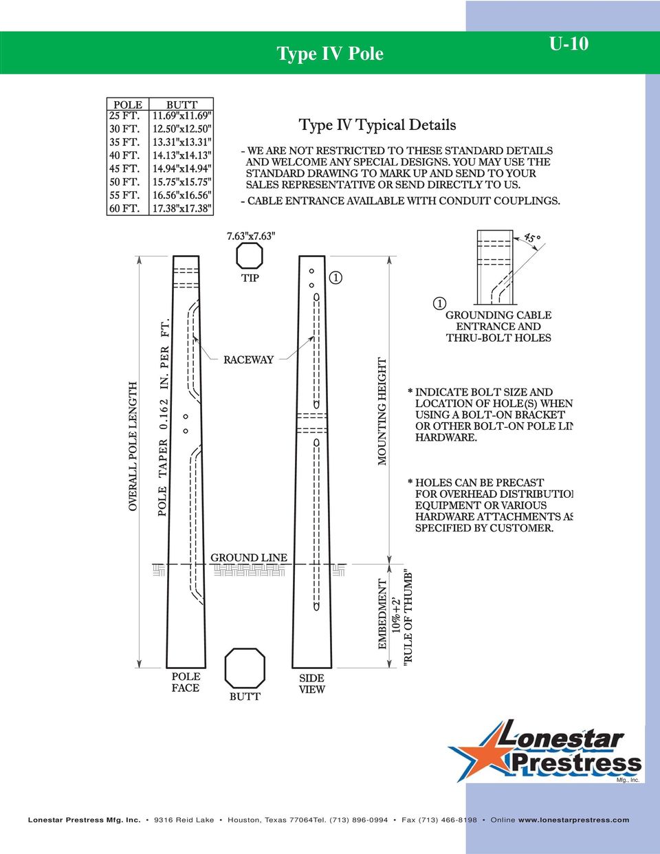
10 U-9 Type IV Pole Type IV Technical Chart Used for Power Distribution - Heavy Duty Direct Embedment CATALOG NUMBER SMOOTH GRAY MOUNTING HEIGHT WEIGHT OVERALL LENGTH SIZE (In.) TIP BUTT 90 EPA AT TIP (Sq. Ft.) ULTIMATE GROUNDLINE MOMENT (Ft. Lbs.) BREAKING LOAD 2 Ft. FROM TIP , ,200 3, , ,300 4, , ,300 4, , ,800 4, , ,400 4, , ,200 4, , ,400 4, , ,900 4,118 GENERAL INFORMATION 1. Different colors, finishes and exposed aggregates are available upon request. 2. All corners are chamfered. 3. 7,000 PSI concrete is standard; higher strengths are available if required. 4. STRENGTH: In most cases a higher ground line moment and a higher breaking strength and EPA can be attained without going to a larger pole. 5. EFFECTIVE PROJECTED AREA (EPA): Lonestar Prestress Mfg. concrete poles and mounting arms have been designed in accordance with accepted engineering practices to be structurally capable of withstanding wind loads and velocity pressure up to 140 (gust speed) per ASCE Poles to meet higher wind loads are available. 6. HOLES: Holes are precast to meet your specifications and requirements for mounting attachments, most any desired arrangement can be provided. The prestressing cables are located so that field drilling is permitted on the centerline of either axis. Field drilling can be accomplished with the use of rotary hammer drills. 7. INSTALLATION: Lonestar Prestress Mfg. concrete poles are designed for setting directly into the ground, without the use of precast foundations, similar to the setting of wood poles. After the hole is drilled, the pole is set and plumbed, the earth is then backfilled and tamped. The depth is dependent on the nature of the soil and the anticipated load. Where it is impossible to embed the poles in the ground, such as on bridges or overpasses, a boltdown base plate is available. 8. To specify a base plate for base mounted poles add the suffix BP to catalog numbers. Customer to supply the bolt circle drawings or template.

11 Type IV Pole U-10
12 U-11 Type V Pole Type V Pole Technical Chart Used for Power Distribution - Light Duty Direct Embedment CATALOG NUMBER SMOOTH GRAY MOUNTING HEIGHT WEIGHT OVERALL LENGTH SIZE (In.) TIP BUTT 90 EPA AT TIP (Sq. Ft.) ULTIMATE GROUNDLINE MOMENT (Ft. Lbs.) BREAKING LOAD 2 Ft. FROM TIP , ,800 5, , * ,700 4, , * ,700 4, , * ,300 4, , * ,300 4, , * ,700 4, , * ,900 4, , * ,000 4, , * ,000 4,207 GENERAL INFORMATION * Subject to future availability 1. Different colors, finishes and exposed aggregates are available upon request. 2. All corners are chamfered. 3. 7,000 PSI concrete is standard; higher strengths are available if required. 4. STRENGTH: In most cases a higher ground line moment and a higher breaking strength and EPA can be attained without going to a larger pole. 5. EFFECTIVE PROJECTED AREA (EPA): Lonestar Prestress Mfg. concrete poles and mounting arms have been designed in accordance with accepted engineering practices to be structurally capable of withstanding wind loads and velocity pressure up to 140 (gust speed) per ASCE Poles to meet higher wind loads are available. 6. HOLES: Holes are precast to meet your specifications and requirements for mounting attachments, most any desired arrangement can be provided. The prestressing cables are located so that field drilling is permitted on the centerline of either axis. Field drilling can be accomplished with the use of rotary hammer drills. 7. INSTALLATION: Lonestar Prestress Mfg. concrete poles are designed for setting directly into the ground, without the use of precast foundations, similar to the setting of wood poles. After the hole is drilled, the pole is set and plumbed, the earth is then backfilled and tamped. The depth is dependent on the nature of the soil and the anticipated load. Where it is impossible to embed the poles in the ground, such as on bridges or overpasses, a boltdown base plate is available. 8. To specify a base plate for base mounted poles add the suffix BP to catalog numbers. Customer to supply the bolt circle drawings or template.

13 Type V Pole U-12

Sports and High Mast Lighting Poles Phone: (866) 474-7200 Fax: (817) 924-7049
 474-7200 Fax: (817) 924-7049") Sports and High Mast Lighting Poles 4 High Mast Lighting Poles General American LitePole offers a raising and lowering system that allows for ease of maintaining the lighting system at ground level. Ideal
Sports and High Mast Lighting Poles 4 High Mast Lighting Poles General American LitePole offers a raising and lowering system that allows for ease of maintaining the lighting system at ground level. Ideal
Report on. Wind Resistance of Signs supported by. Glass Fiber Reinforced Concrete (GFRC) Pillars
 Pillars") Report on Wind Resistance of Signs supported by Glass Fiber Reinforced Concrete (GFRC) Pillars Prepared for US Sign and Fabrication Corporation January, 2006 SUMMARY This study found the attachment of
Report on Wind Resistance of Signs supported by Glass Fiber Reinforced Concrete (GFRC) Pillars Prepared for US Sign and Fabrication Corporation January, 2006 SUMMARY This study found the attachment of
Special Research Topic Report on Current Practice in Utility Distribution Poles and Light Poles. Adam Crosby. Date 5/05/11
 Special Research Topic Report on Current Practice in Utility Distribution Poles and Light Poles 1.0 Objective Adam Crosby Date 5/05/11 The objective of this report is to present a summary of the current
MAST ARMS & POLES. Ornamental Pole Top & Bases
 Ornamental Pole Top & Bases Pelco s decorative pole top and bases help make the traffic signal aesthetically pleasing to the eye. Available for various pole diameters and multiple finish options. Ornamental
NEGRP TEST SUMMARY. Joseph A. Lanzoni, November 2005
 NEGRP TEST SUMMARY Joseph A. Lanzoni, November 2005 The National Electrical Grounding Research Project (NEGRP) was a project managed and sponsored by the National Fire Protection Association (NFPA) Research
Technical Notes 3B - Brick Masonry Section Properties May 1993
 Technical Notes 3B - Brick Masonry Section Properties May 1993 Abstract: This Technical Notes is a design aid for the Building Code Requirements for Masonry Structures (ACI 530/ASCE 5/TMS 402-92) and Specifications
RadianceRail Installation Guide
 RadianceRail Installation Guide Installing RadianceRail with CableRail by Feeney... 2 Installing CableRail by Feeney for RadianceRail... 7 Installing RadianceRail Stairs with CableRail by Feeney... 10
TECHNICAL SPECIFICATION SERIES 8000 PRECAST CONCRETE
 TECHNICAL SPECIFICATION SERIES 8000 PRECAST CONCRETE TECHNICAL SPECIFICATION PART 8000 - PRECAST CONCRETE TABLE OF CONTENTS Item Number Page 8100 PRECAST CONCRETE CONSTRUCTION - GENERAL 8-3 8101 General
GLOSSARY OF TERMINOLOGY
 GLOSSARY OF TERMINOLOGY AUTHORIZED PILE LENGTHS - (a.k.a. Authorized Pile Lengths letter) Official letter stating Engineer's recommended length of concrete piles to be cast for construction of foundation.
PTS HELICAL PIERS INSTALLATION SPECIFICATIONS NOTICE
 FORM A PTS HELICAL PIERS INSTALLATION SPECIFICATIONS NOTICE The following suggested specifications are written as a guide to assist the specifier in writing his own specifications. Specific circumstances
Chapter 3 Pre-Installation, Foundations and Piers
 Chapter 3 Pre-Installation, Foundations and Piers 3-1 Pre-Installation Establishes the minimum requirements for the siting, design, materials, access, and installation of manufactured dwellings, accessory
AZEK Rail Install Guide
 TRIM MOULDING DECK PORCH RAIL PAVERS AZEK Rail Install Guide Installing AZEK Rail with CableRail by Feeney... 1 Installing CableRail by Feeney for AZEK Rail... 7 Installing AZEK Rail Stairs with CableRail
TS 813 GROUNDING AND BONDING TTD 813.001 TRAFFIC SIGNAL INSTALLATION AND CONTROLLER CABINET GROUNDING SYSTEM TTD 813.005 CONTROLLER CABINET GROUNDING
 TORONTO TRANSPORTATION January 2012 TS 813 GROUNDING AND BONDING TABLE OF CONTENTS 1. DRAWINGS TTD 813.001 TRAFFIC SIGNAL INSTALLATION AND CONTROLLER CABINET GROUNDING SYSTEM TTD 813.005 CONTROLLER CABINET
Pole Data Sheets (CDN) INFRASTRUCTURE FOR LIFE
 INFRASTRUCTURE FOR LIFE") Data Sheets (CDN) INFRASTRUCTURE FOR LIFE RS Technologies www.rstandard.com Email Toll Free Phone Fax info@grouprsi.com +1 877 219 8002 +1 403 219 8000 +1 403 219 8001 2421 37th Avenue NE, Suite 400 Calgary,
Data Sheets (CDN) INFRASTRUCTURE FOR LIFE RS Technologies www.rstandard.com Email Toll Free Phone Fax info@grouprsi.com +1 877 219 8002 +1 403 219 8000 +1 403 219 8001 2421 37th Avenue NE, Suite 400 Calgary,
DENVER MODEL 30 X 30 SPECIFICATIONS
 DENVER MODEL 30 X 30 SPECIFICATIONS Dimensions: Roof Dimensions 30-0 x 30-0 (4) Columns (Center to Center) 25-6½ x 25-6½ Minimum Clearance 8-0 Roof Height @ Peak Dependent on Col. Ht. Hip Roof 4:12 pitch
GUIDELINES FOR UTILITY INSTALLATIONS Part 1 - Wire Lines and Communications Cables
 Engineering Department SEPTEMBER, 2007 GUIDELINES FOR UTILITY INSTALLATIONS Part 1 - Wire Lines and Communications Cables General Requirements This section applies to all public and private utilities,
SECTION 02845 GUARDRAILS
 SECTION 02845 GUARDRAILS PART 1 - GENERAL 1.01 SCOPE OF WORK A. Furnish all labor, materials, equipment and incidentals necessary and repair, replace or install all types of guardrails as specified herein
Residential Deck Safety, Construction, and Repair
 Juneau Permit Center, 4 th Floor Marine View Center, (907)586-0770 This handout is designed to help you build your deck to comply with the 2006 International Residential Building code as modified by the
Panel Session: Structural Reliability-Based Design of Utility Poles and the National Electrical Safety Code
 1 Panel Session: Structural Reliability-Based Design of Utility Poles and the National Electrical Safety Code Nelson Bingel, Habib Dagher, Ronald Randle, Ronald Wolfe, Lawrence Slavin*, Michael Voda, Jerry
Socket P2RF-05-S P2RF-08-S Clip & Release Lever R99-11 nameplate for MY
 Screwless Clamp Terminal Socket Screwless clamping greatly contributes to reducing wiring time. No over or under tightening of cable connection so better contact reliability is achieved. Double wiring
Requirements for the Attachment of Communication Cable Facilities on PPL Poles
 Page 99 of 137 Requirements for the Attachment of Communication Cable Facilities on Replaces: URS-3002 URS-3004 URS-101C-304 A-157649 Page 100 of 137 Reference Notes for Drawings: General 1. The term communication
Safe & Sound Bridge Terminology
 Safe & Sound Bridge Terminology Abutment A retaining wall supporting the ends of a bridge, and, in general, retaining or supporting the approach embankment. Approach The part of the bridge that carries
Pole Guying More Complicated Than Meets the Eye. NRECA TechAdvantage 2014 Presented by Jason Settle, P.E. jason.settle@gdsassociates.
 Pole Guying More Complicated Than Meets the Eye NRECA TechAdvantage 2014 Presented by Jason Settle, P.E. jason.settle@gdsassociates.com Pole Guying Strength of components NESC vs. RUS Guy Factor Grounding
LEGACY REPORT ER-5110. www.icc-es.org. ICC Evaluation Service, Inc. Reissued November 1, 2003. Legacy report on the 1997 Uniform Building Code
 LEGACY REPORT Reissued November 1, 2003 ICC Evaluation Service, Inc. www.icc-es.org Business/Regional Office # 5360 Workman Mill Road, Whittier, California 90601 # (562) 699-0543 Regional Office # 900
Optimum proportions for the design of suspension bridge
 Journal of Civil Engineering (IEB), 34 (1) (26) 1-14 Optimum proportions for the design of suspension bridge Tanvir Manzur and Alamgir Habib Department of Civil Engineering Bangladesh University of Engineering
March 14, 2007. Installation of Bay, Bow and Garden Windows
 March 14, 2007 Re: Installation of Bay, Bow and Garden Windows Attached are the Atrium Companies, Inc recommendation for the installation of bay, bow and garden windows. These instructions were developed
PUMP JACK SYSTEM AND ACCESSORIES
 Pump Jack Model # 2200 A low cost, easy to operate, safe, portable scaffolding built of rugged steel. It's perfect for shingling, siding, sheathing, insulating, painting, building, roofing, home repair
Construction Specifications for Keyhole Pavement Coring and Reinstatement
 F I N A L Construction Specifications for Keyhole Pavement Coring and Reinstatement Gas Technology Institute 1700 S. Mount Prospect Rd. Des Plaines, Illinois 60018 www.gastechnology.org Version 13 October
Fixed Access Ladders. Table of Contents. 1. Legislative Requirements
 Fixed Access Ladders Engineering Data Sheet 2-04 Revised: January 1997 Table of Contents 1. Legislative Requirements 2. General 3. Rungs 4. Side Rails 5. Safety Cages 6. Attachment & Anchoring 7. Platforms
High Strain Dynamic Load Testing of Drilled Shafts
 Supplemental Technical Specification for High Strain Dynamic Load Testing of Drilled Shafts SCDOT Designation: SC-M-712 (9/15) September 3, 2015 1.0 GENERAL This work shall consist of performing high-strain
MANUFACTURED HOUSING USED AS DWELLINGS
 MANUFACTURED HOUSING USED AS DWELLINGS SECTION AE101 SCOPE AE101.1 General. These provisions shall be applicable only to a manufactured home used as a single dwelling unit and shall apply to the following:
Structural Failures Cost Lives and Time
 Structural Failures Cost Lives and Time Recent failures of storage bins, silos and other structures highlight the need to increase awareness of hazards associated with these structures. Since 2010, one
Evolve LED Area Light
 GE Lighting Evolve LED Area Light Scalable Area Light (EASA) imagination at work Product Features The next evolution of the GE Evolve LED Area Light continues to deliver outstanding features, while adding
SUPPLEMENTAL TECHNICAL SPECIFICATIONS BI-DIRECTIONAL STATIC LOAD TESTING OF DRILLED SHAFTS
 July 14, 2015 1.0 GENERAL BI-DIRECTIONAL STATIC LOAD TESTING OF DRILLED SHAFTS This work shall consist of furnishing all materials, equipment, labor, and incidentals necessary for conducting bi-directional
By SP Partners, LLC. www.rainbowatticstair.com INSTALLATION GUIDE. Prestige
 By SP Partners, LLC www.rainbowatticstair.com INSTALLATION GUIDE Prestige IMPORTANT READ THIS FIRST Inspect stair for any damage prior to installation. Stair is NOT to be installed while home is under
Overhang Bracket Loading. Deck Issues: Design Perspective
 Deck Issues: Design Perspective Overhang Bracket Loading Deck overhangs and screed rails are generally supported on cantilever brackets during the deck pour These brackets produce an overturning couple
Cable Runways & Accessories
 SB17U SB13AL SB17 SB17T SB117 SB17HRB SB2107 SB2101A SB17VRB SB2110A SB2129 SB2129SD SB130 SB2221 SB126 SB2118 SB119 SB2105 113 Cooper B-Line manufactures a wide variety of high quality cable pathway products
TECHNICAL MEMORANDUM SUMMARY REPORT:
 Texas Transportation Institute The Texas A&M University System 3135 TAMU College Station, TX 77843-3135 979-845-6375 Fax: 979-845-6107 http://tti.tamu.edu TECHNICAL MEMORANDUM Contract No.: T4541-AO Test
Transmission Foundations. helical piles and guy anchors for transmission structures. www.hubbellpowersystems.com
 Transmission Foundations helical piles and guy anchors for transmission structures www.hubbellpowersystems.com Grid locked on your transmission job? Instant Foundation helical piles go places concrete
PVC PIPE PERFORMANCE FACTORS
 PVC PIPE PERFORMANCE FACTORS PVC pipe, like all flexible pipe products, is very dependent on the surrounding soil for its structural capacity, in addition, the pipe material must have sufficient inherent
WHI 90-Minute Rated Veneered Door Frame Installation Instructions
 No. 940-03-10 INSTALLATION INSTRUCTIONS 90 MINUTE RATED VENEERED DOOR FRAME DOOR REQUIREMENTS: Consult the door manufacturer to make sure that the doors are qualified for the hardware to be installed,
ENGINEERING SPECIFICATION PULTRUDED DYNARAIL FIBERGLASS LADDER & LADDER CAGES
 ENGINEERING SPECIFICATION PULTRUDED DYNARAIL FIBERGLASS LADDER & LADDER CAGES PART 1 - GENERAL 1.1 SCOPE OF WORK SECTION 06610 FIBERGLASS REINFORCED PLASTICS (FRP) FABRICATIONS PULTRUDED SQUARE TUBE LADDER
Operations and Instruction Manual Might Swivel - Part # 310273 Concrete and Steel Anchorage Connector ANSI Z359.1 10,000 lbs / 44kn
 Safety.. Operations and Instruction Manual Might Swivel - Part # 310273 Concrete and Steel Anchorage Connector ANSI Z359.1 10,000 lbs / 44kn Description: Technical: Zinc plated forged heat treated steel,
COLORADO MODEL. 35 x 65 SPECIFICATIONS
 COLORADO MODEL 35 x 65 SPECIFICATIONS Dimensions: Roof Dimensions 35-0 x 65-0 Column Dimensions (center to center) 31-0 x 30-6 Minimum Clearance 14-0 Roof Height @ Peak ±18-8 Curved Roof ±42-6 radius Square
This digital document created and presented by Richard Fleetwood. He is the. Civil Defense Now! (http://www.survivalring.org/cd-main.htm) websites.
 websites.") This digital document created and presented by Richard Fleetwood. He is the founder, author, producer, and webmaster of the SurvivalRing (http://www.survivalring.org) and Civil Defense Now! (http://www.survivalring.org/cd-main.htm)
This digital document created and presented by Richard Fleetwood. He is the founder, author, producer, and webmaster of the SurvivalRing (http://www.survivalring.org) and Civil Defense Now! (http://www.survivalring.org/cd-main.htm)
Regional and Site Assumptions This document is based on the following regional and site assumptions:
 Structural Criteria for Residential Rooftop Solar Energy Installations Use of this document This toolkit document includes a one-page list of structural criteria for over-the-counter or online approval,
Reinforced Concrete Design
 FALL 2013 C C Reinforced Concrete Design CIVL 4135 ii 1 Chapter 1. Introduction 1.1. Reading Assignment Chapter 1 Sections 1.1 through 1.8 of text. 1.2. Introduction In the design and analysis of reinforced
Wastewater Capital Projects Management Standard Construction Specification
 CITY AND COUNTY OF DENVER ENGINEERING DIVISION Wastewater Capital Projects Management Standard Construction Specification 10.1 Precast Concrete Pipe 10.1.1 General This section covers material requirements,
CHAIN-LINK FENCES BID SPECIFICATIONS DESCRIPTION
 CHAIN-LINK FENCES BID SPECIFICATIONS DESCRIPTION 1 This item shall consist of furnishing and erecting Chain-Link fence in accordance with these specifications and the details shown on the plans and in
Chapter 5 FLOOR LOADING AND WEIGHTS
 Chapter 5 FLOOR LOADING AND WEIGHTS Section 1.0 Floor Loading Section 2.0 Seismic Data The CT system has a total floor load of approximately 6660 lbs (3021 kg). About 5050 lbs (2291 kg), including patient
Bolting: Attachment Of The Mudsill To The Foundation
 Bolting: Attachment Of The Mudsill To The Foundation If the mudsill of a house (the pink area in the illustration at right) is not bolted, the lateral loads (back and forth motions) of an earthquake can
EVALUATION OF DUAL CABLE SIGNAL SUPPORT SYSTEMS
 EVALUATION OF DUAL CABLE SIGNAL SUPPORT SYSTEMS By JESSICA L. RIGDON A THESIS PRESENTED TO THE GRADUATE SCHOOL OF THE UNIVERSITY OF FLORIDA IN PARTIAL FULFILLMENT OF THE REQUIREMENTS FOR THE DEGREE MASTER
Analysis of the Interstate 10 Twin Bridge s Collapse During Hurricane Katrina
 Analysis of the Interstate 0 Twin Bridge s Collapse During Hurricane Katrina By Genda Chen, Emitt C. Witt III, David Hoffman, Ronaldo Luna, and Adam Sevi The Interstate 0 Twin Span Bridge over Lake Pontchartrain
IHSS-N1 WELDED HONEYCOMB CORE SPECIFICATION. Generated: Sergiy Papyshev Engineering. Approved: Don Prysi Manufacturing. Approved: Merzuk Ramic Quality
 IHSS-N1 WELDED HONEYCOMB CORE SPECIFICATION Generated: Sergiy Papyshev Engineering Approved: Don Prysi Manufacturing Approved: Merzuk Ramic Quality Approved: Steven Barnett Administrative DATE DATE DATE
Lighthouse Engineering, L.L.C.
 Registered Engineering Firm (F: 9334) Phone: 214-577-1077 Fax: 214-224-0549 Website: www.lighthouseeng.com Email: Office@LighthouseEng.com Thursday, September 04, 2014 TO: Our Client RE: Initial Engineering
V.A PJM Design and Application of Overhead Transmission Lines 69kV and Above
 V.A PJM Design and Application of Overhead Transmission Lines 69kV and Above These design criteria have been established to assure acceptable reliability of the bulk transmission system facilities. These
PRESTRESSED CONCRETE. Introduction REINFORCED CONCRETE CHAPTER SPRING 2004. Reinforced Concrete Design. Fifth Edition. By Dr. Ibrahim.
 CHAPTER REINFORCED CONCRETE Reinforced Concrete Design A Fundamental Approach - Fifth Edition Fifth Edition PRESTRESSED CONCRETE A. J. Clark School of Engineering Department of Civil and Environmental
Design of Steel Structures Prof. S.R.Satish Kumar and Prof. A.R.Santha Kumar. Fig. 7.21 some of the trusses that are used in steel bridges
 7.7 Truss bridges Fig. 7.21 some of the trusses that are used in steel bridges Truss Girders, lattice girders or open web girders are efficient and economical structural systems, since the members experience
Fall Protection System: A system put in place to protect workers from falling. (i.e. installation of guardrails, fall arrest, fall restraint, etc.
 SWP (6) FALL PROTECTION PROGRAM The following information on Fall Protection has been based around the BC OHS Regulations, standards, policies and guidelines. Prior to starting work outside of BC, the
1997 Uniform Administrative Code Amendment for Earthen Material and Straw Bale Structures Tucson/Pima County, Arizona
 for Earthen Material and Straw Bale Structures SECTION 70 - GENERAL "APPENDIX CHAPTER 7 - EARTHEN MATERIAL STRUCTURES 70. Purpose. The purpose of this chapter is to establish minimum standards of safety
June 2007 CHAPTER 7 - CULVERTS 7.0 CHAPTER 7 - CULVERTS 7.1 GENERAL
 7.0 7.1 GENERAL For the purpose of this manual, culverts are defined as structures that are completely surrounded by soil and located below the surface of the roadway parallel to the general direction
CONSTRUCTION STANDARD ELECTRIC OPERATIONS ORGANIZATION
 Page 1 of 11 ****This Standard Supercedes BECo CS2.13-2.3 & ComElectric OH Construction Manual, System Grounding Section, drawings CGND, GRDSUM, and C2**** 1.0 Bill of Materials GROUNDING AND BONDING POLE-MOUNTED
Section 21. Telecommunication Hardware. www.geindustrial.com BuyLog Catalog 21-1
 Introduction...21-1 Fiber Closure Hardware...21-2 Cable Location Surge Protectors...21-4 Introduction GE has been manufacturing Telecommunication Hardware products for over 20 years and has become a leader
Concrete Repair. Applications and Procedures
 Concrete Repair Applications and Procedures Objectives Identify what surface preparation is needed Identify typical modes of failure and testing methods How to choose the correct material for the repair
Pelco manufactures a variety of sign brackets in rigid and free-swinging mounts for both flat and internally illuminated signs.
 Astro Sign-rac Overhead Street Name Signs Stellar Series A-0502 Sign Clamp AS-3004 AS-3009 Astro Sign-rac, Stellar and Mount for Overhead Street Name Signs AS-0128 - - - and and : 29, 36, 42, 48, 56, 72,
Guidelines for Earthquake Bracing of Residential Water Heaters
 Guidelines for Earthquake Bracing of Residential Water Heaters Department of General Services Division of the State Architect 1102 Q Street, Suite 5100 Sacramento, CA 95814 Phone: (916) 324-7099 Fax: (916)
HURRICANE MITIGATION RETROFITS FOR EXISTING SITE-BUILT SINGLE FAMILY RESIDENTIAL STRUCTURES
 HURRICANE MITIGATION RETROFITS FOR EXISTING SITE-BUILT SINGLE FAMILY RESIDENTIAL STRUCTURES 101 Retrofits Required. Pursuant to Section 553.844 553.884, Florida Statutes, strengthening of existing site-built,
ATLANTA MODEL SPECIFICATIONS
 ATLANTA MODEL 50 SPECIFICATIONS Dimensions: Roof Dimensions (point to point) 50-0 Column Dimensions (out to out of columns) 44-0 Eave Height 8-0 Roof Height @ Peak ±21-8⅞ Hip Roof 6:12 pitch Square Feet
picomax The Pluggable Connection System
 picomax The Pluggable Connection System TECHNOLOGY THIS SPECIALIZED CAN T MEET ALL REQUIREMENTS. YES IT CAN. CONTENTS picomax Pin spacing: 3. mm/0.138 in;.0 mm/0.197 in; 7. mm/0.29 in Versatile Pluggable
Evolve LED Area Light
 GE Lighting Evolve LED Area Light Scalable Area Light (EASB) imagination at work Product Features The next evolution of the GE Evolve LED Area Light continues to deliver outstanding features, while adding
Shake. Northwest. Charcoal. Brown Antique. Taupe Antique. Grey Antique
 Rooflines by Northwest Shake Creating an authentic Northwest look with the durability only Columbia Roof Tile can promise, this unique profile enhances the beauty of a traditional style home and offers
ENGINEERING SPECIFICATION FIBERGRATE MOLDED GRATING. January 24, 2014 06610-1
 ENGINEERING SPECIFICATION FIBERGRATE MOLDED GRATING January 24, 2014 06610-1 SECTION 06610 FIBERGLASS REINFORCED PLASTICS (FRP) FABRICATIONS MOLDED GRATING PART 1 - GENERAL 1.1 SCOPE OF WORK A. The CONTRACTOR
Elo Touch Solutions Wall-mounting Kit for the 5501L IDS Touchmonitors
 Installation Manual Elo Touch Solutions Wall-mounting Kit for the 5501L IDS Touchmonitors SW602206 Rev B Table of Contents Chapter 1: Safety Warning... 3 Chapter 2: Kit Contents... 4 Included in Kit...
9300BC SERIES Light Commercial Door Closer
 Light Commercial Door Closer general information The 9300BC is a durable, economically priced door closer designed for commercial exterior and interior doors such as storefront and industrial applications.
ICC-ES Evaluation Report
 ICC-ES Evaluation Report ESR-2369 Reissued May 1, 2010 This report is subject to re-examination in one year. www.icc-es.org (800) 423-6587 (562) 699-0543 A Subsidiary of the International Code Council
Detailing of Reinforcment in Concrete Structures
 Chapter 8 Detailing of Reinforcment in Concrete Structures 8.1 Scope Provisions of Sec. 8.1 and 8.2 of Chapter 8 shall apply for detailing of reinforcement in reinforced concrete members, in general. For
In-Ground Basketball System Owners Manual
 In-Ground Basketball System Owners Manual Customer Service Center N53 W4700 South Corporate Circle Sussex, WI 53089 U.S.A. Write Model Number From Box Here: WARNING! 3 Capable Adults REQUIRED TOOLS AND
ENGINEERING SPECIFICATION PULTRUDED DYNAFORM FIBERGLASS STRUCTURAL SHAPES. July 1, 2008 Revision 2
 ENGINEERING SPECIFICATION PULTRUDED DYNAFORM FIBERGLASS STRUCTURAL SHAPES 1 PART 1 - GENERAL 1.0 GENERAL 1.1 REFERENCES: SECTION 06610 FIBERGLASS REINFORCED PLASTICS (FRP) FABRICATIONS PULTRUDED FIBERGLASS
Rittal s Comprehensive Family Of... NETWORK RACK SOLUTIONS
 Rittal s Comprehensive Family Of... NETWORK RACK SOLUTIONS STANDARD & ECONOMICAL BasicRack A complete low-cost, high-quality basic equipment management system. Design Six web channel holes per side allow
SMarT_Foundation [Simple Modular Technology] Assembly and Installation Instructions (U.S. Patent Pending)
![SMarT_Foundation [Simple Modular Technology] Assembly and Installation Instructions (U.S. Patent Pending)](/thumbs/32/15409120.jpg "SMarT_Foundation [Simple Modular Technology] Assembly and Installation Instructions (U.S. Patent Pending)") SMarT_Foundation [Simple Modular Technology] Assembly and Installation Instructions (U.S. Patent Pending) Southwest Windpower Skystream 3.7 Wind Turbine with Towers up to 21.3 m (70 ft.) in Height AnemErgonics
SMarT_Foundation [Simple Modular Technology] Assembly and Installation Instructions (U.S. Patent Pending) Southwest Windpower Skystream 3.7 Wind Turbine with Towers up to 21.3 m (70 ft.) in Height AnemErgonics
The Concrete Life Cycle: Maintain to Sustain. Fred Goodwin BASF Construction Chemicals (EB-N) Beachwood OH
 Beachwood OH") The Concrete Life Cycle: Maintain to Sustain Fred Goodwin BASF Construction Chemicals (EB-N) Beachwood OH What is Concrete? Concrete: Instant rock -just add water to make a hard wet sponge. A composite
The Concrete Life Cycle: Maintain to Sustain Fred Goodwin BASF Construction Chemicals (EB-N) Beachwood OH What is Concrete? Concrete: Instant rock -just add water to make a hard wet sponge. A composite
SECTION 5: SANITARY SEWER SYSTEM DESIGN
 SECTION 5: SANITARY SEWER SYSTEM DESIGN 5.01 GENERAL Sanitary sewer improvements shall be designed to serve the ultimate level of City development as defined in the General Plan and the Wastewater Facilities
Outline MICROPILES SUBJECT TO LATERAL LOADING. Dr. Jesús Gómez, P.E.
 MICROPILES SUBJECT TO LATERAL LOADING Dr. Jesús Gómez, P.E. Micropile Design and Construction Seminar Las Vegas, NV April 3-4, 2008 Outline When are micropiles subject to lateral load? How do we analyze
Electric Engineering Division FIBER CONDUIT RULES AND REGULATIONS
 Electric Engineering Division FIBER CONDUIT RULES AND REGULATIONS TABLE OF CONTENTS I. RULES AND REGULATIONS A. TABLE OF CONTENTS... 2 B. TERMS AND DEFINITIONS... 3 C. DEVELOPER S/CONTRACTOR S RESPONSIBILITIES...
DESIGN OF PRESTRESSED BARRIER CABLE SYSTEMS
 8601 North Black Canyon Highway Suite 103 Phoenix, AZ 8501 For Professionals Engaged in Post-Tensioning Design Issue 14 December 004 DESIGN OF PRESTRESSED BARRIER CABLE SYSTEMS by James D. Rogers 1 1.0
HIGH TENSION CABLE BARRIER
 Special Provision September 11, 2006 SECTION 02845 S HIGH TENSION CABLE BARRIER PART 1 GENERAL 1.1 SECTION INCLUDES A. Cable barrier materials and installation procedures. 1.2 RELATED SECTIONS A. Section
Operating, Installation, and Maintenance Instructions
 ELKHART BRASS MFG. CO., INC. 1302 WEST BEARDSLEY AVENUE P.O. BOX 1127 ELKHART IN 46515 (574) 295-8330 FAX (574) 293-9914 Operating, Installation, and Maintenance Instructions RAM Personal Portable Monitor
SECTION 02720 SANITARY SEWER AND STORM DRAIN SYSTEMS
 SECTION 02720 SANITARY SEWER AND STORM DRAIN SYSTEMS PART 1 GENERAL 1.01 SECTION INCLUDES A. The requirements for pipe material and installation in sewer and drainage collection systems. All materials
Specifications, Product Testing and Terminology
 Specifications, Product Testing and Terminology The following synopsis provides a review of various material and final product testing, which is performed on our products, as well as, many of our competitors.
CHAPTER 9 LONG TERM MONITORING AT THE ROUTE 351 BRIDGE
 CHAPTER 9 LONG TERM MONITORING AT THE ROUTE 351 BRIDGE 9.1 INTRODUCTION An important reason that composite piles have not gained wide acceptance in the civil engineering practice is the lack of a long
REINFORCED CONCRETE. Reinforced Concrete Design. A Fundamental Approach - Fifth Edition. Walls are generally used to provide lateral support for:
 HANDOUT REINFORCED CONCRETE Reinforced Concrete Design A Fundamental Approach - Fifth Edition RETAINING WALLS Fifth Edition A. J. Clark School of Engineering Department of Civil and Environmental Engineering
SPECIFICATIONS FOR BOON EDAM TOMSED MODEL TUT-65TMB
 SPECIFICATIONS FOR BOON EDAM TOMSED MODEL TUT-65TMB PRODUCT DESCRIPTION: BOON EDAM TOMSED MODEL TUT-65TMB STAINLESS STEEL BARCODE SCANNING ELECTRONIC REGISTERING TURNSTILE SCOPE OF OPERATION: A. The TUT-65TMB
determining wind and snow loads for solar panels America s Authority on Solar
 determining wind and snow loads for solar panels America s Authority on Solar Determining wind and snow loads for solar panels 1 introduction As one of the largest and most established vertically integrated
Arecont Vision H.264 Color or Day/Night SurroundVideo Series Installation Manual
 0 P a g e H.264 Color or Day/Night SurroundVideo Installation Manual Inside the box: A. Arecont Vision SurroundVideo camera B. Mounting template C. RJ45 female to female coupler D. Hex key E. Security
SPECIFICATIONS FOR THE INSTALLATION OF FIRE ALARM SYSTEMS, SPRINKLER SYSTEMS, AND MASTER BOXES IN THE POQUONNOCK BRIDGE FIRE DISTRICT
 SPECIFICATIONS FOR THE INSTALLATION OF FIRE ALARM SYSTEMS, SPRINKLER SYSTEMS, AND MASTER BOXES IN THE POQUONNOCK BRIDGE FIRE DISTRICT The purpose of these specifications is to insure that there are minimum
PC-Concrete Injectable Concrete Anchoring and Repair System
 PC-Concrete Injectable Concrete Anchoring and Repair System DESCRIPTION: PC-Concrete is a two component (1:1 ratio), 100% solids, high modulus, structural epoxy paste. PC-Concrete is a solvent free, no
Underground Commercial Electric Service
 Underground Commercial Electric Service SCANA Corporation 2013 Revised: June 2013 Table of Contents SECTION PAGE I. Specification and Requirements 2 A. General B. Definition of Terms C. Company and Developer
FIX TURE CARRI ERS. 140(a) MPB-2011-USA
 MPB-2011-USA") FIXTURE CARRIERS STRUCTURAL FEET The feet are heavy duty cast ductile iron and invertible. No distinction is necessary between right and left hand. Each foot wraps around the specially formed edge of the
FIXTURE CARRIERS STRUCTURAL FEET The feet are heavy duty cast ductile iron and invertible. No distinction is necessary between right and left hand. Each foot wraps around the specially formed edge of the
Cabinets 101: Configuring A Network Or Server Cabinet
 Cabinets 101: Configuring A Network Or Server Cabinet North, South and Central America White Paper May 2012 www.commscope.com Contents Background Information 3 What is a network or server cabinet? 3 What
Residential Building Permits Information
 City of Bonham Building Department 514 Chestnut St. Bonham, Texas 75418 OFFICE: (903) 583-7555 FAX: (903)583-5761 Residential Building Permits Information Application for Permits: To apply for a permit,