C H A P T E R 7 THE WANKEL ROTARY ENGINE. 7.1 A Different Approach to the Spark-Ignition Engine
|
|
|
- Edmund Summers
- 10 years ago
- Views:
Transcription
1 261 C H A P T E R 7 THE WANKEL ROTARY ENGINE 7.1 A Different Approach to the Spark-Ignition Engine The reciprocating internal combustion engine has served mankind for over a century, and will continue to do so for the foreseeable future. The Wankel rotary engine, a much more recent development, is said to have been conceived in its present form in 1954 (ref. 2). An implementation of the rotary engine used in the 1990 Mazda RX-7 automobile and its turbocharger are shown in Figures 7.1(a) and 7.1(b). As of 1987, over 1.5 million Wankel engines had been used in Mazda automobiles (ref. 6). The rotary engine has a host of advantages that make it a formidable contender for some of the tasks currently performed by reciprocating engines. The piston in a fourstroke-cycle reciprocating engine must momentarily come to rest four times per cycle as its direction of motion changes. In contrast, the moving parts in a rotary engine are in continuous unidirectional motion. Higher operating speeds, ease of balancing, and absence of vibration are a few of the benefits. The high operating speeds allow the engine to produce twice as much power as a reciprocating engine of the same weight. It has significantly fewer parts and occupies less volume than a reciprocating engine of comparable power. With all these advantages, why are there so few Wankel engines in service? Part of the answer lies in the reciprocating engine s remarkable success in so many applications and its continuing improvement with research. Why change a good thing? Manufacturing techniques for reciprocating engines are well known and established, whereas production of rotary engines requires significantly different tooling. It must be admitted, however, that the rotary engine has some drawbacks. A major problem of the Wankel automobile engine is that it does not quite measure up to the fuel economy of some automotive reciprocating SI engines. It is the judgment of some authorities that it does not offer as great a potential for improvement in fuel economy and emissions reduction as reciprocating and gas turbine engines. However, although the rotary engine may never dominate the automotive industry, it is likely to find applications where low weight and volume are critical, such as in sports cars, general aviation, and motorcycles.
 and 7.1(b). As of 1987, over 1.")
2 262 While the rotary engine may not enjoy the great success of reciprocating engines, it is worthy of study as an unusual and analytically interesting implementation of the familiar Otto cycle. Even the present success of this latter-day Otto engine should serve as an inspiration to those who search for novel ways of doing things. This chapter is a tribute to Felix Wankel and those who are helping to develop this remarkable engine. 7.2 Rotary Engine Operation Figure 7.2 shows a cross-section of a rotary engine. The stationary housing encloses a moving triangular rotor that rotates with its apexes in constant contact with the housing inner surface. Air and combustion gases are transported in the spaces between the rotor and the housing. The rotor rides on an eccentric that is an integral part of a shaft, as shown in the dual rotor crank shaft of Figure 7.3(a). The housing and rotor of a rotary engine designed for aircraft application are shown in Figure 7.3(b). The operation of the Wankel engine as an Otto-cycle engine may be understood by following in Figure 7.4 the events associated with the counterclockwise movement of a gas volume isolated between the housing and one of the rotor flanks. The air-fuel mixture may be supplied, by a conventional carburetor, through the intake port labeled I in Figure 7.4(a). As the shaft and rotor turn, the intake port is covered, trapping a fixed mass of air and fuel (assuming no leakage). This is analogous to the gas mass captured within the cylinder-piston volume by closure of a reciprocating engine intake valve. As the rotor continues to turn, the captured (crosshatched) volume contained

3 between the rotor and housing decreases, compressing the air-fuel mixture [part (b)]. When it reaches the minor diameter, the active mixture volume is a minimum corresponding to the volume at top center in the reciprocating engine. One or more spark plugs, as indicated at the top of each housing, initiate combustion, causing rapid rises in pressure and temperature [part (c)]. The hot, high-pressure combustion gas [part (d)] transmits a force to the eccentric through the rotor. Note that, during the 263

4 264
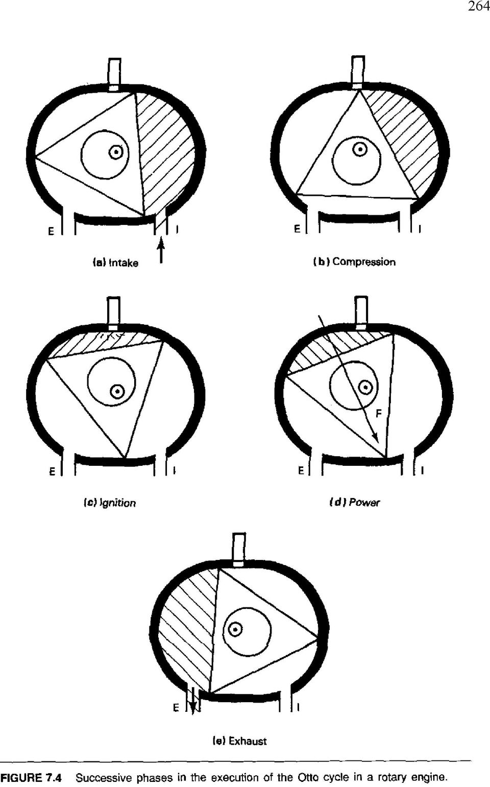
5 265 power phase, the line of action of the force F provides a counterclockwise torque acting about the shaft axis. As the rotation proceeds, the expanding gases drive the rotor until the exhaust port is exposed, releasing them [part (e)]. The exhaust process continues as the intake port opens to begin a new cycle. This port overlap is apparent in the lower volume shown in part (b). In summary, each flank of the rotor is seen to undergo the same intake, compression, ignition, power, and exhaust processes as in a four-stroke-cycle reciprocating Otto engine. All three flanks of the rotor execute the same processes at equally spaced intervals during one rotor rotation. Hence three power pulses are delivered per rotation of the rotor. Because there are three shaft rotations per rotor rotation, the Wankel engine has one power pulse per shaft rotation. Thus it has twice as many power pulses as a singlecylinder four-stroke-cycle reciprocating engine operating at the same speed, a clear advantage in smoothness of operation. This feature of one power pulse per shaft rotation causes many people to compare the Wankel engine with the two-stroke-cycle reciprocating engine. 7.3 Rotary Engine Geometry The major elements of the rotary engine the housing and the rotor are shown in cross-section in Figure 7.2. The housing inner surface has a mathematical form known as a trochoid or epitrochoid. A single-rotor engine housing may be thought of as two parallel planes separated by a cylinder of epitrochoidal cross-section. Following the notation of Figure 7.5, the parametric form of the epitrochoid is given by x = e cos 3 + Rcos [ft m] (7.1a) y = e sin 3 + R sin [ft m] (7.1b) where e is the eccentricity and R is the rotor center-to-tip distance. For given values of e and R, Equations (7.1) give the x and y coordinates defining the housing shape when is varied from 0 to 360 degrees. The rotor shape may be thought of as an equilateral triangle, as shown in Figures 7.2 and 7.4 (flank rounding and other refinements are discussed later in the chapter). Because the rotor moves inside the housing in such a way that its three apexes are in constant contact with the housing periphery, the positions of the tips are also given by equations of the form of Equations (7.1): x = e cos 3 + R cos( + 2n*/3) [ft m] (7.2a) y = e sin 3 + R sin( + 2n*) [ft m] (7.2b) where n = 0, 1, or 2, the three values identifying the positions of the three rotor tips, each separated by 120. Because R represents the rotor center-to-tip distance, the

6 266 motion of the center of the rotor can be obtained from Equations (7.2) by setting R = 0. The equations and Figure 7.5 indicate that the path of the rotor center is a circle of radius e. Note that Equations (7.1) and (7.2) can be nondimensionalized by dividing through by R. This yields a single geometric parameter governing the equations, e/r, known as the eccentricity ratio. It will be seen that this parameter is critical to successful performance of the rotary engine. The power from the engine is delivered to an external load by a cylindrical shaft. The shaft axis coincides with the axis of the housing, as seen in Figure 7.2. A second circular cylinder, the eccentric, is rigidly attached to the shaft and is offset from the shaft axis by a distance, e, the eccentricity. The rotor slides on the eccentric. Note that the axes of the rotor and the eccentric coincide. Gas forces exerted on the rotor are transmitted to the eccentric to provide the driving torque to the engine shaft and to the external load. The motion of the rotor may now be understood in terms of the notation of Figure 7.5. The line labeled e rotates with the shaft and eccentric through an angle 3, while the line labeled R is fixed to the rotor and turns with it through an angle about the moving eccentric center. Thus the entire engine motion is related to the motion of these two lines. Clearly, the rotor (and thus line R) rotates at one-third of the speed of the shaft, and there are three shaft rotations for each rotor revolution.

7 267 EXAMPLE 7.1 Derive expressions for the major (largest) and minor (smallest) diameters of an epitrochoid in terms the notation of Figure 7.5. Solution The major diameter is defined by adding the lengths of the lines representing the eccentricity and the rotor radius when they are horizontal and colinear or by using Equation 7.1(a). Thus the major diameter at y = 0 corresponds to = 0 and 180, for which x = e + R and x = e R, respectively. The distance between these x coordinates is the length of the major diameter 2(e + R). The minor diameter is similarly defined along x = 0, but with e and R lines oppositely directed. The two cases correspond to = 90 and 270. For = 90, the e line is directed downward and the R line upward in Figure 7.5. This yields y = R e and, by symmetry, the minor diameter is 2(R e). Hence Major diameter = 2(R + e) Minor diameter = 2(R e) 7.4 A Simple Model for a Rotary Engine Additional important features of the rotary engine can be easily studied by considering an engine with an equilateral triangular rotor. Figure 7.6 shows the rotor in the position where a rotor flank defines the minimum volume. We will call this position top center, TC, by analogy to the reciprocating engine. The rotor housing clearance parameter, d, is the difference between the housing minor radius, R e, and the distance from the housing axis to mid-flank, e + R cos 60 = e + R/2: d = (R e) (e + R/2) = R/2 2e [ft m] (7.3) Setting the clearance to zero establishes an upper limiting value for the eccentricity ratio: (e/r) crit = 1/4. Study of Equations (7.1), at the other extreme, shows that, for e/r = 0, the epitrochoid degenerates to a circle. In this case the rotor would spin with no eccentricity and thus produce no compression and no torque. Thus, for the flat-flanked rotor, it is clear that usable values of e/r lie between 0 and Now let's examine some other fundamental parameters of the flat-flanked engine model. Consider the maximum mixture volume shown in Figure 7.7. For a given rotor width w, the maximum volume can be determined by calculating the area between the housing and the flank of the rotor. Using Equations (7.1), the differential area 2y dx can be written as:

8 268

9 269 da max = 2y dx = 2(e sin3 + R sin) d(e cos3 + R cos) [ft 2 m 2 ] (7.4) Dividing by R 2 and differentiating on the right-hand side, we obtain an equation for the dimensionless area in terms of the eccentricity ratio and the angle : A max /R 2 = 2 [(e/r)sin3 + sin][3(e/r)sin3 + sin]d [dl] (7.5) In order for the differential area to sweep over the maximum trapped volume in Figure 7.7, the limits on the angle must vary from 0 to 60. Thus integration of Equation (7.5) with these limits and using standard integrals yields A max /R 2 = * [(e/r) 2 + 1/3] 3 1/2 /4[1 6(e/R)] [dl] (7.6) Similarly, using Figure 7.6 and the differential volume shown there, the nondimensionalized minimum area can be written as: A min /R 2 = * [(e/r) 2 + 1/3] 3 1/2 /4 [1 + 6(e/R)] [dl] (7.7) These maximum and minimum volumes (area-rotor width products) are analogous to the volumes trapped between the piston and cylinder at BC and TC in the four-stroke reciprocating engine. In that engine the difference between the volumes at BC and TC is the displacement volume, and their ratio is the compression ratio. A little thought should convince the reader that the analogy holds quantitatively for the displacement and compression ratio of the rotary engine. Therefore, subtracting Equation (7.7) from Equation (7.6) gives the displacement for a rotor width w for one flank of the flat-flanked engine as disp = 3 (3 1/2 wr 2 (e/r) [ft 3 m 3 ] (7.8) and forming their ratio yields the compression ratio as A max /R 2 * [(e/r) 2 + 1/3] 3 1/2 /4[1 6(e/R)] CR = = [dl] (7.9) A min /R 2 * [(e/r) 2 + 1/3] 3 1/2 /4 [1 + 6(e/R)] Thus the displacement increases with increases in rotor width, the square of the rotor radius, and with the eccentricity ratio, whereas the compression ratio is independent of size but increases with increase in eccentricity ratio.
![sin][3(e/r)sin3 + sin]d [dl] (7.5) In order for the differential area to sweep over the maximum trapped volume in Figure 7.7, the limits on the angle must vary from 0 to 60.](/docs-images/57/6827335/images/page_9.jpg "Thus integration of Equation (7.5) with these limits and using standard integrals yields A max /R 2 = * [(e/r) 2 + 1/3] 3 1/2 /4[1 6(e/R)] [dl] (7.6) Similarly, using Figure 7.")
10 270 EXAMPLE 7.2 What are the displacement and the compression ratio for a flat-flanked rotary engine with a rotor radius of 10 cm, an eccentricity of 1.5 cm, and a rotor width of 2.5 cm? Solution For this engine, e/r = 1.5/10 = Equation (7.8) then yields the displacement: 3(3) 0.5 (0.15)(10) 2 (2.5) = cm 3 or (194.9)(0.0610) = in. 3 Equation (7.9) can be written as CR = (a + b)/(a b) where a = ( )[(0.15) 2 + 1/3] 3 1/2 /4 = , and b = 3( 3 1/2 (0.15)/2 = Then CR = ( )/( ) = 3.64 The very low compression ratio of Example 7.2 would yield a poor Otto-cycle thermal efficiency. The compression ratio could be increased by increasing e/r, but it would still be low for most applications. It is therefore important to consider the favorable influence of flank rounding on rotary engine performance. 7.5 The Circular-Arc-Flank Model While the triangular rotor model represents a possible engine and is useful as a learning tool, such an engine would perform poorly compared with one having a rotor with rounded flanks. A more realistic model is one in which the triangular rotor is augmented with circular-arc flanks, as shown in Figure 7.8. The radius of curvature, r, of a flank could vary from infinity, corresponding to a flat flank, to a value for which the arc touches the minor axis of the epitrochoid. Note that the center of curvature of an arc terminated by two flank apexes depends on the value of r. It can also be seen from Figure 7.8 that r is related to the angle,, subtended by the flank arc by or r sin( /2) = R sin(*/3) = 3 1/2 R/2 [ft m] r/r = 3 1/2 /[2sin( /2)] [dl] (7.10) Thus either the included angle,, or the radius of curvature, r, may be used to define the degree of flank rounding for a given rotor radius R.
![14159)[(0.15) 2 + 1/3] 3 1/2 /4 = 0.6849, and b = 3( 3 1/2 (0.15)/2 = 0.3897. Then CR = (0.6849 + 0.3897)/(0.6849-0.3897) = 3.64 The very low compression ratio of Example 7.](/docs-images/57/6827335/images/page_10.jpg "2 would yield a poor Otto-cycle thermal efficiency. The compression ratio could be increased by increasing e/r, but it would still be low for most applications.")
11 271 Clearance with Flank Rounding The additional area obtained by capping a side of a triangle with a circular arc is called a segment. The segment height, h, shown in Figure 7.8, is the difference between r and the projection of r on the axis of symmetry: h/r = (r/r)[1 cos( /2)] [dl] (7.11) Substitution of Equation (7.10) in Equation (7.11) yields h/r = 3 1/2 [1 cos( /2)] / [2sin( /2)] [dl] (7.12) It is evident from the figure that the clearance for the rotor with circular arc flanks is the difference between the clearance of the flat-flanked rotor and h. Thus, using Equation (7.3), the clearance is given by d/r = 1/2 2(e/R) 3 1/2 [1 cos( /2)] / [2sin( /2)] [dl] (7.13) In a real engine, of course, the clearance must be non-negative.
![11) yields h/r = 3 1/2 [1 cos( /2)] / [2sin( /2)] [dl] (7.](/docs-images/57/6827335/images/page_11.jpg "12) It is evident from the figure that the clearance for the rotor with circular arc flanks is the difference between the clearance of the flat-flanked rotor and h.")
12 272 Added Volume per Flank Due to Rounding The segment area is the difference between the pie-shaped area of the sector subtended by its included angle,, and the enclosed triangular area. The sector area, or volume per unit rotor width, is the fraction of the area of a circle of radius, r, subtended by the angle ; i.e., * r 2 ( /2* ) = r 2 /2. Thus using Equation (7.10), the dimensionless segment volume is A s /R 2 = (A sec A tri ) /R 2 = (r/r) 2 ( sin ) /2 = (3/8)( sin ) /sin 2 /2 [dl] (7.14) Displacement and Compression Ratio It was pointed out earlier that the displacement of the flat-flanked engine is the difference between the maximum and minimum capture volumes, and is given by Equation (7.8). This is true also for the engine with rounded flanks. The additional volume added to the rotor by flank rounding subtracts from both of the flat-flanked maximum and minimum capture volumes, leaving the difference unchanged. Thus the displacement of one flank of a rounded-flank engine is disp = 3 (3 1/2 wr 2 (e/r) [ft 3 m 3 ] (7.15) Likewise, the ratio of the maximum and minimum capture volumes given by Equations (7.6) and (7.7), corrected for the segment volume from Equation (7.14) provides a relation for the rounded-flank engine compression ratio: * [(e/r) 2 + 1/3] 3 1/2 /4 [1 6(e/R)] A s /R 2 CR = [dl] (7.16) * [(e/r) 2 + 1/3] 3 1/2 /4 [1 + 6(e/R)] A s /R 2 The added rotor volume due to rounding subtracts from the flat-flanked capture volumes and therefore reduces the denominator of Equation (7.16) more than the numerator. As a result, the compression ratio is greater for rounded-flank than for flatflanked engines. Rotary engines usually have the maximum rounding possible consistent with adequate engineering clearances. Effect of the Recess Volume Equation (7.16) accounts for flank rounding but not for the recess usually found in rotor flanks. The additional capture volume associated with the recess is seen in Figure 7.9. Its influence on the displacement and compression ratio may be reasoned in the
![10), the dimensionless segment volume is A s /R 2 = (A sec A tri ) /R 2 = (r/r) 2 ( sin ) /2 = (3/8)( sin ) /sin 2 /2 [dl] (7.](/docs-images/57/6827335/images/page_12.jpg "14) Displacement and Compression Ratio It was pointed out earlier that the displacement of the flat-flanked engine is the difference between the maximum and minimum capture volumes, and is given by")
13 273 same way as with the segment volume. The recess increases both minimum and maximum mixture volumes by the same amount. It therefore has no effect on displacement and it decreases the compression ratio. Figure 7.10 shows the influence of flank rounding and recession on clearance and compression ratio. While flank recession reduces the compression ratio for given values of and e/r, it improves the shape of the long, narrow combustion pocket forming the minimum capture volume. Rotary engines usually have more than one spark plug, to help overcome the combustion problems associated with this elongated shape. EXAMPLE 7.3 Rework Example 7.2, taking into account a flank-arc included angle of 0.65 radians. What is the flank clearance for this engine? Solution Because flank rounding does not influence it, the displacement is still cm 3. Equation (7.16) rewritten using the notation of Example 7.2 becomes

14 274 CR = (a + b A s /R 2 ) / (a b A s /R 2 ) where A s /R 2 = (3/8)[0.65 sin(0.65)]/sin 2 (0.65/2) = Then the compression ratio is CR = [ ] / [ ] = 6.98 This represents a significant improvement over the value of 3.64 for the flat-flanked rotor. The flank clearance is given by Equation (7.13): d = 10{0.5 2(0.15) 3 1/2 [1 cos(0.65/2)]} / [2sin(0.65/2)] = 0.58 cm. We have already noted that the displacement volume associated with one flank of the rotary engine produces one power stroke during each rotor revolution and during three shaft rotations. Because there are three flanks per rotor, a rotor executes one complete thermodynamic cycle per shaft rotation. Thus the power produced by a single rotor is determined by the displacement volume of a single flank and the rotational speed: (disp [cm 3 /Rev])(MEP [kn/cm 2 ])(N [Rev/min]) Power = (60 [sec/min])(100 [cm/m]) [kw] or (disp [in 3 /Rev])(MEP [lb/in 2 ])(N [Rev/min]) Power = (12 [in/ft])(33,000 [ft-lb/hp-min]) [HP] 7.6 Design and Performance of the Wankel Engine It is evident from Figure 7.4 that, in the Wankel engine, the opening and closing of the intake and exhaust ports by the motion of the rotor apexes serves a function equivalent to that of mechanical valves in reciprocating engines. This simple operation in the Wankel engine eliminates the need for many of the moving parts required by the reciprocating engine, such as cams, camshafts, tappets, valves, and lifters. There are, in fact, many more parts in a reciprocating engine than in a comparable rotary engine. However, sealing at the apexes and sides of the rotor is critical for efficient operation of the rotary engine. Significant pressure differences between the three active mixture volumes of a rotor in different phases of the Otto cycle require efficient seals
![65/2)] = 0.58 cm.](/docs-images/57/6827335/images/page_14.jpg "We have already noted that the displacement volume associated with one flank of the rotary engine produces one power stroke during each rotor revolution and during three shaft rotations.")
15 275 analogous to piston rings in the reciprocating engine. These are needed to avoid leakage between adjacent volumes, which causes a loss of compression and power. Seal friction has been estimated to account for about 25% of rotary engine friction. Spring loaded, self-lubricating apex seals, as shown in Figure 7.11, allow for sliding with low friction over the treated-chrome-alloy-plated housing inner surface. The figure shows improvements in apex seal design (ref. 6). The three-piece seal design, with two leaf springs rather than one, decreases seal mass through reduced thickness, and offers a configuration that promotes area contact rather than line contact between seal and rotor. Side seals are also important to maintain pressure integrity of each flank mixture pocket. Reductions in the thickness of both apex and side seals have decreased friction with the housing by reducing the seal area producing the friction-

16 276 causing normal force on the housing. Oil seals, also on the rotor sides, are used to control oil consumption. Though the peripheral intake port shown in Figures 7.4 and 7.9 provides better performance under heavy loads than a single side port, its associated intake-exhaust port overlap may allow excessive flow of exhaust gas into the fresh mixture, causing unreliable combustion in low-speed operation. Consequently, one or more side intake ports, in addition to or instead of a peripheral intake port, are sometimes used. Side ports, of course, are also opened and closed by rotor motion. In addition to reducing intake-exhaust overlap at light loads, side intake ports also induce combustionenhancing swirl in the air-fuel mixture. It is evident that the moving combustion volume at the time of ignition has a long and narrow flame propagation path. Rounded rotor flanks are usually recessed to provide a wider flame front path between the two lobes of the active volume. In highspeed operation, the brief time for combustion may dictate additional design features. Multiple spark plugs, swirl induced by side intake ports and multiple ports, the "squish" produced by the the relative motion of the walls of the active volume, fuel injection, and stratified-charge design all can contribute to improvement of the combustion process. It may be noted in Figures 7.3 and 7.9 that an internal ring gear is attached to the rotor. This gear meshes with a stationary gear attached to the engine housing. The function of this gearset is to position the rotor as the shaft turns not to transmit torque. Engine torque, as indicated earlier, is transmitted by direct contact of surface forces between the rotor and the eccentric. Stratified-Charge Rotary Engine Reference 7 discusses the design and performance of stratified-charge rotary engines developed for commercial aviation propulsion and APU (auxiliary power unit) application as well as for marine, industrial, and military requirements. Figure 7.12 shows a direct fuel injection configuration that has performed well under a wide range of speed, load, and environmental conditions and with a variety of liquid fuels. The reference reports a lack of octane and cetane sensitivities, so that diesel, gasoline, and jet fuel can all be used with this configuration. As air in the rotor recess passes below, the spark plug ignites a locally rich pilot stream that in turn ignites the fuel from the main injector. The net fuel-air ratio is lean, resulting in improved fuel economy over normal carburetion. Figure 7.13 presents data for full-load brake horsepower and specific fuel consumption obtained with Jet-A fuel for the twin-rotor 2034R engine. The maximum takeoff power at 5800 rpm was 430 horsepower, with a brake specific fuel consumption (BSFC) of 0.44 lb m /BHP-hr. Throughout a range of loads and altitude conditions the engine operates with a fuel-air ratio between and 0.037, well below the stoichiometric value. The reference reports a best thermal efficiency of 35.8% (BSFC = lb m /BHP-hr) at 3500 rpm and 225-horsepower output.

17 277

18 278 Closure Continued engineering research on the rotary engine has resulted in performance improvements through improved seals, lean-burn combustion, fuel injection, integral electronic control, improved intake design, weight reduction, and turbocharging. Despite vehicle weight increases, the Mazda RX-7 with a two-rotor 80-in.3 -displacement engine improved 9.4% in fuel consumption and 8% in power output between 1984 and 1987 (ref. 6). During this time period, the addition to the engine of a turbocharger with intercooling increased its power output by 35%. Reference 8 reports that the Mazda RX-Evolv, a year-2000 concept car, has a naturally-aspirated rotary engine called RENESIS. The two-rotor, side intake and exhaust engine is reported to have reduced emissions and improved fuel economy and to have attained 280 horsepower at 9000 rpm and 226 N-m torque at 8000 rpm. EXAMPLE 7.4 If the BMEP of the in 3 -diplacement engine in Example 7.2 is 150 psi at 4000 rpm, what is the brake horsepower? Solution The brake horsepower is or BHP = (150)(4000)(11.89)/(12)(33000) = 18 horsepower BHP = (18)(0.746) =13.44kW Bibliography and References 1. Cole, David E. "The Wankel Engine," Scientific American, Vol. 227, No. 2, (August 1972): Ansdale, R. F., The Wankel R C Engine. South Brunswick, N.J.: A. S. Barnes, Yamamoto, Kenichi, Rotary Engine, Tokyo: Sankaido Co., Weston, Kenneth C. "Computer Simulation of a Wankel Rotary Engine Analysis and Graphics." Proceedings of the Conference of the Society for Computer Simulation, July 1986, pp Weston, Kenneth C., "Computerized Instruction in the Design of the Wankel Rotary Engine." ASEE Annual Conference Proceedings, June 1988.

19 Fujimoto, Y. et al., "Present and Prospective Technologies of Rotary Engine." Society of Automotive Engineers Paper , Mount, Robert E., and LaBouff, Gary A., Advanced Stratified-Charge Rotary Engine Design. Society of Automotive Engineers Paper (also in SAE SP-768, Rotary Engine Design; Analysis and Developments), Jost, Kevin, (ed.), Global Concepts Mazda RX Evolv, Automotive Engineering International, Vol 8, No.8, (August 2000), p 59. EXERCISES 7.1 Using graph paper, plot, on a single sheet, epitrochoids for e/r = 0, 0.15, 0.2, 0.25, 0.3, and 0.4. On a separate sheet, draw the epitrochiod and the triangular rotor for three rotor positions (separated by 30 ) for the case of e/r = Verify the results of Example 7.1 by specializing Equations (7.1) for the appropriate values of. 7.3 Derive Equation (7.5) using a differential area given by (x x f ) dy, where x f is the constant x-coordinate of the flank. 7.4 Following the approach in the derivation of Equations (7.3) (7.6), and using the notation of Figure 7.6, derive Equation (7.7). 7.5 Derive Equation (7.7) using a differential area (y y f ) dx, where y f is the constant y-coordinate of the flank. 7.6 Derive Equation (7.8). 7.7 Derive Equation (7.9). 7.8 Show that the radius of curvature for a circular-arc flank that touches the epitrochoid at its midpoint is given by r/r = 1 e/r + 3(e/R)/(1 4e/R) 7.9 Use Equation (7.13) to derive an expression for the limiting value of e/r as a function of the flank included angle. Plot the limiting value of e/r as a function of the included angle Solve Example 7.3, accounting for a rotor flank recess of 3% of R 2 w.
 for the case of e/r = 0.15. 7.2 Verify the results of Example 7.")
20 7.11 If combustion takes place in an engine rotor rotation interval of 40 in an engine operating at 8000 rpm, how much time is available for the combustion process? * Develop a single-column spreadsheet that determines the compression ratio, clearance ratio, and nondimensional displacement for a given value of e/r and flank-rounding angle. Use a copy command to replicate the column, forming a table of alternative design characteristics, for a reasonable range of rounding angles. 7.13* Use the spreadsheet graphics option to develop plots of compression ratio and clearance ratio, as seen in Figure A snowmobile single-rotor Wankel engine developed 6.65 brake horsepower at 5500 rpm with a displacement volume of 108 cc and a compression ratio of 8.5. The fuel consumption was 2.77 lb m /hr. Determine the BMEP (in psi), the BSFC (in lb m /hp-min), the brake torque (in lb f -ft), and the brake thermal efficiency, assuming a fuel heating value of 18,900 Btu/lb m A rotary engine mounted on a dynamometer develops 23 lb f -ft of torque at 5000 rpm. When driven by a motor-generator at the same speed, a torque of 7 lb f -ft is required. Determine the brake and indicated horsepower and the engine mechanical efficiency. What additional information is needed to determine the indicated mean effective pressure? 7.16 A rotary engine has an eccentricity of 2 in. and an equilateral triangular rotor with a tip radius of 10 in. (a) Determine the major and minor diameters of the epitrochoidal housing. (b) Sketch the housing and its axes of symmetry and the rotor when it is in the nominal spark-plug firing position. (c) For the configuaration of part (b), determine the minimum rotor clearance. (d) Write equations for the relations between the shaft speed (rpm), the spark plug firing rate (FR), and the rotor speed (RS). Identify any new symbols used A rotary engine has an eccentricity of 3 cm and an equilateral triangular rotor with a tip radius of 13 cm. (a) Determine the major and minor diameters of the epitrochoidal housing. (b) Sketch the housing and its axes of symmetry and the rotor when it is in the nominal spark-plug firing position. (c) For the configuaration of part (b), determine the minimum rotor clearance.

21 (d) Write equations for the relations between the shaft speed (rpm), the spark plug firing rate (FR), and the rotor speed (RS). Identify any new symbols used A rotary engine with a flat-flanked rotor has a ratio of maximum to minimum housing inside diameters of 1.4. What is the engine compression ratio? 7.19 The major diameter of the epitrochoidal housing of a flat-flanked single-rotor industrial rotary engine is 39.6 inches. The engine turns at 1000 rpm while delivering 500 brake horsepower at a BMEP of 79.2 psi. If the eccentricity ratio is 0.14, what are the minor diameter, the rotor thickness, and the rotor displacement, [in.3 ]? 7.20 A flat-flanked dual-rotor industrial rotary engine has a 60-cm minor diameter.the engine delivers 800kW from an IMEP of 700kPa at a shaft speed of 20 rps. The mechanical efficiency is 89%, and the eccentricity ratio is Determine the major diameter and the thickness and displacement of each rotor A Wankel rotary engine has an eccentricity of 2.2 in. and a major diameter of 28 in. It has a compression ratio of 9.5 and a 600 in.3 displacement. Determine the rotor width and the rotor sector included angle if the rotor flanks are circular and have no indentations A Wankel rotary engine has an eccentricity of 2.5 cm and a major diameter of 32 cm. The engine compression ratio is 9.0, and the displacement is 540 cm 3. What are the eccentricity ratio, the rotor width, and the rotor sector included angle if the rotor flanks are circular and have no indentations? 281
Chapters 7. Performance Comparison of CI and SI Engines. Performance Comparison of CI and SI Engines con t. SI vs CI Performance Comparison
 Chapters 7 SI vs CI Performance Comparison Performance Comparison of CI and SI Engines The CI engine cycle can be carried out in either 2 or 4 strokes of the piston, with the 4-cycle CI engine being more
Principles of Engine Operation
 Internal Combustion Engines ME 422 Yeditepe Üniversitesi Principles of Engine Operation Prof.Dr. Cem Soruşbay Information Prof.Dr. Cem Soruşbay İstanbul Teknik Üniversitesi Makina Fakültesi Otomotiv Laboratuvarı
INTERNAL COMBUSTION (IC) ENGINES
 ENGINES") INTERNAL COMBUSTION (IC) ENGINES An IC engine is one in which the heat transfer to the working fluid occurs within the engine itself, usually by the combustion of fuel with the oxygen of air. In external
INTERNAL COMBUSTION (IC) ENGINES An IC engine is one in which the heat transfer to the working fluid occurs within the engine itself, usually by the combustion of fuel with the oxygen of air. In external
EXPERIMENT NO. 3. Aim: To study the construction and working of 4- stroke petrol / diesel engine.
 EXPERIMENT NO. 3 Aim: To study the construction and working of 4- stroke petrol / diesel engine. Theory: A machine or device which derives heat from the combustion of fuel and converts part of this energy
Unit 24: Applications of Pneumatics and Hydraulics
 Unit 24: Applications of Pneumatics and Hydraulics Unit code: J/601/1496 QCF level: 4 Credit value: 15 OUTCOME 2 TUTORIAL 1 HYDRAULIC PUMPS The material needed for outcome 2 is very extensive so there
REDESIGN OF THE INTAKE CAMS OF A FORMULA STUDENT RACING CAR
 FISITA2010-SC-P-24 REDESIGN OF THE INTAKE CAMS OF A FORMULA STUDENT RACING CAR Sándor, Vass Budapest University of Technology and Economics, Hungary KEYWORDS valvetrain, camshaft, cam, Formula Student,
Unit 24: Applications of Pneumatics and Hydraulics
 Unit 24: Applications of Pneumatics and Hydraulics Unit code: J/601/1496 QCF level: 4 Credit value: 15 OUTCOME 2 TUTORIAL 3 HYDRAULIC AND PNEUMATIC MOTORS The material needed for outcome 2 is very extensive
MECHANICAL ENGINEERING EXPERIMENTATION AND LABORATORY II EXPERIMENT 490.07 ENGINE PERFORMANCE TEST
 MECHANICAL ENGINEERING EXPERIMENTATION AND LABORATORY II EXPERIMENT 490.07 ENGINE PERFORMANCE TEST 1. Objectives To determine the variation of the brake torque, brake mean effective pressure, brake power,
OUTCOME 2 INTERNAL COMBUSTION ENGINE PERFORMANCE. TUTORIAL No. 5 PERFORMANCE CHARACTERISTICS
 UNIT 61: ENGINEERING THERMODYNAMICS Unit code: D/601/1410 QCF level: 5 Credit value: 15 OUTCOME 2 INTERNAL COMBUSTION ENGINE PERFORMANCE TUTORIAL No. 5 PERFORMANCE CHARACTERISTICS 2 Be able to evaluate
Engine Heat Transfer. Engine Heat Transfer
 Engine Heat Transfer 1. Impact of heat transfer on engine operation 2. Heat transfer environment 3. Energy flow in an engine 4. Engine heat transfer Fundamentals Spark-ignition engine heat transfer Diesel
CLASSIFICATION OF INTERNAL COMBUSTION ENGINES VARIOUS TYPES OF ENGINES
 CLASSIFICATION OF INTERNAL COMBUSTION ENGINES VARIOUS TYPES OF ENGINES CLASSIFICATION OF INTERNAL COMBUSTION ENGINES 1. Application 2. Basic Engine Design 3. Operating Cycle 4. Working Cycle 5. Valve/Port
Introductory Study of Variable Valve Actuation for Pneumatic Hybridization
 2007-01-0288 Introductory Study of Variable Valve Actuation for Pneumatic Hybridization Copyright 2007 SAE International Sasa Trajkovic, Per Tunestål and Bengt Johansson Division of Combustion Engines,
CFD INVESTIGATIONS OF MIXTURE FORMATION, FLOW AND COMBUSTION FOR MULTI-FUEL ROTARY ENGINE
 CFD INVESTIGATIONS OF MIXTURE FORMATION, FLOW AND COMBUSTION FOR MULTI-FUEL ROTARY ENGINE Von der Fakultät für Maschinenbau, Elektrotechnik and Wirtschafts- Ingenieurwesen der Brandenburgischen Technischen
SOLID MECHANICS TUTORIAL MECHANISMS KINEMATICS - VELOCITY AND ACCELERATION DIAGRAMS
 SOLID MECHANICS TUTORIAL MECHANISMS KINEMATICS - VELOCITY AND ACCELERATION DIAGRAMS This work covers elements of the syllabus for the Engineering Council exams C105 Mechanical and Structural Engineering
UNIT 3 AUTOMOBILE ELECTRICAL SYSTEMS
 UNIT 3 AUTOMOBILE ELECTRICAL SYSTEMS Automobile Electrical Structure 3.1 Introduction Objectives 3.2 Ignition System 3.3 Requirement of an Ignition System 3.4 Types of Ignition 3.4.1 Battery or Coil Ignition
The Mazda way to improve relations between people, the automobile and the planet
 New Technology [Reference exhibit] The Mazda way to improve relations between people, the automobile and the planet Mazda is committed to creating better relations between the motorized society and the
Copyright 2011 Casa Software Ltd. www.casaxps.com. Centre of Mass
 Centre of Mass A central theme in mathematical modelling is that of reducing complex problems to simpler, and hopefully, equivalent problems for which mathematical analysis is possible. The concept of
Practice Problems on Boundary Layers. Answer(s): D = 107 N D = 152 N. C. Wassgren, Purdue University Page 1 of 17 Last Updated: 2010 Nov 22
: D = 107 N D = 152 N. C. Wassgren, Purdue University Page 1 of 17 Last Updated: 2010 Nov 22") BL_01 A thin flat plate 55 by 110 cm is immersed in a 6 m/s stream of SAE 10 oil at 20 C. Compute the total skin friction drag if the stream is parallel to (a) the long side and (b) the short side. D =
BL_01 A thin flat plate 55 by 110 cm is immersed in a 6 m/s stream of SAE 10 oil at 20 C. Compute the total skin friction drag if the stream is parallel to (a) the long side and (b) the short side. D =
Experimental Optimization and Analysis of Intake and Exhaust Pipeline for Small Engine Motorcycle
 Journal of Applied Science and Engineering, Vol. 15, No. 1, pp. 21 30 (2012) 21 Experimental Optimization and Analysis of Intake and Exhaust Pipeline for Small Engine Motorcycle Chien-Jong Shih 1 *, Chi-Nan
The Ogunmuyiwa Engine Cycle
 The Ogunmuyiwa Engine Cycle Dapo Ogunmuyiwa M.Sc VDI Chairman / CEO Tel: (+49) 162 961 04 50 E-mail: [email protected] Ogunmuyiwa Motorentechnik GmbH Technologie- und Gruenderzentrum (TGZ) Am Roemerturm
Hydrogen as a fuel for internal combustion engines
 Hydrogen as a fuel for internal combustion engines Contents: Introduction External mixture formation for hydrogen operated engines Experimental engine for hydrogen in Stralsund Internal mixture formation
CENTRIFUGAL PUMP OVERVIEW Presented by Matt Prosoli Of Pumps Plus Inc.
 CENTRIFUGAL PUMP OVERVIEW Presented by Matt Prosoli Of Pumps Plus Inc. 1 Centrifugal Pump- Definition Centrifugal Pump can be defined as a mechanical device used to transfer liquid of various types. As
Pump ED 101. Positive Displacement Pumps. Part I Reciprocating Pumps
 Pump ED 101 Positive Displacement Pumps Part I Reciprocating Pumps Joe Evans, Ph.D http://www.pumped101.com There are many pump designs that fall into the positive displacement category but, for the most
Gear Trains. Introduction:
 Gear Trains Introduction: Sometimes, two or more gears are made to mesh with each other to transmit power from one shaft to another. Such a combination is called gear train or train of toothed wheels.
Spherical engine/generator-unit can boost electrical car dynamics
 Spherical engine/generator-unit can boost electrical car dynamics Automobile: Cars run singely on battaries have a range of approx. 150 km. Electrical cars with "range-extender" have the same range as
Section 1.1. Introduction to R n
 The Calculus of Functions of Several Variables Section. Introduction to R n Calculus is the study of functional relationships and how related quantities change with each other. In your first exposure to
Energy Savings through Electric-assist Turbocharger for Marine Diesel Engines
 36 Energy Savings through Electric-assist Turbocharger for Marine Diesel Engines KEIICHI SHIRAISHI *1 YOSHIHISA ONO *2 YUKIO YAMASHITA *3 MUSASHI SAKAMOTO *3 The extremely slow steaming of ships has become
MCI 35.80a AUTOMOTIVE ENGINE MAINTENANCE AND REPAIR MARINE BARRACKS WASHINGTON, D.C.
 MCI 35.80a MARINE CORPS INSTITUTE AUTOMOTIVE ENGINE MAINTENANCE AND REPAIR MARINE BARRACKS WASHINGTON, D.C. UNITED STATES MARINE CORPS MARINE CORPS INSTITUTE 912 POOR STREET SE WASHINGTON, DC 20391-5680
an EnPro Industries company POWERSolutions
 an EnPro Industries company POWERSolutions Steadfast Performer, Trustworthy Reliability, and Relentless Dependability The FM/ALCO engine, a world renowned name well established as a workhorse and prime
Solutions to Exercises, Section 5.1
 Instructor s Solutions Manual, Section 5.1 Exercise 1 Solutions to Exercises, Section 5.1 1. Find all numbers t such that ( 1 3,t) is a point on the unit circle. For ( 1 3,t)to be a point on the unit circle
11.1. Objectives. Component Form of a Vector. Component Form of a Vector. Component Form of a Vector. Vectors and the Geometry of Space
 11 Vectors and the Geometry of Space 11.1 Vectors in the Plane Copyright Cengage Learning. All rights reserved. Copyright Cengage Learning. All rights reserved. 2 Objectives! Write the component form of
Magneto Timing. The selected wire(s) from the magneto(s) distributor must be connected to this cylinder. And the crankshaft/magneto must be spinning.
 from the magneto(s) distributor must be connected to this cylinder. And the crankshaft/magneto must be spinning.") Magneto Timing The two areas of timing a magneto are internal, and external. A number of things must occur at the same time, or in a well orchestrated sequence for the engine to function. Magneto Timing
Magneto Timing The two areas of timing a magneto are internal, and external. A number of things must occur at the same time, or in a well orchestrated sequence for the engine to function. Magneto Timing
Solving Simultaneous Equations and Matrices
 Solving Simultaneous Equations and Matrices The following represents a systematic investigation for the steps used to solve two simultaneous linear equations in two unknowns. The motivation for considering
Belt Drives and Chain Drives. Power Train. Power Train
 Belt Drives and Chain Drives Material comes for Mott, 2002 and Kurtz, 1999 Power Train A power train transmits power from an engine or motor to the load. Some of the most common power trains include: Flexible
Diesel injection, ignition, and fuel air mixing
 Diesel injection, ignition, and fuel air mixing 1. Fuel spray phenomena. Spontaneous ignition 3. Effects of fuel jet and charge motion on mixingcontrolled combustion 4. Fuel injection hardware 5. Challenges
OD1619 PRINCIPLES OF INTERNAL COMBUSTION ENGINES
 SUBCOURSE OD1619 EDITION 8 PRINCIPLES OF INTERNAL COMBUSTION ENGINES US ARMY BRADLEY FIGHTING VEHICLE SYSTEMS MECHANIC CORRESPONDENCE COURSE MOS/SKILL LEVEL: 63T30 PRINCIPLES OF INTERNAL COMBUSTION ENGINES
3516 Industrial Engine
 CAT ENGINE SPECIFICATIONS V-16, 4-Stroke-Cycle Diesel Bore...170.0 mm (6.69 in) Stroke...190.0 mm (7.48 in) Displacement... 69.06 L (4,214.3 in 3 ) Aspiration...Turbocharged / Aftercooled Compression Ratio...13.0:1
UNIT II Robots Drive Systems and End Effectors Part-A Questions
 UNIT II Robots Drive Systems and End Effectors Part-A Questions 1. Define End effector. End effector is a device that is attached to the end of the wrist arm to perform specific task. 2. Give some examples
Engine Friction and Lubrication
 Engine Friction and Lubrication Engine friction terminology Pumping loss Rubbing friction loss Engine Friction: terminology Pumping work: W p Work per cycle to move the working fluid through the engine
CONVERGE Features, Capabilities and Applications
 CONVERGE Features, Capabilities and Applications CONVERGE CONVERGE The industry leading CFD code for complex geometries with moving boundaries. Start using CONVERGE and never make a CFD mesh again. CONVERGE
MECHANICAL PRINCIPLES OUTCOME 4 MECHANICAL POWER TRANSMISSION TUTORIAL 1 SIMPLE MACHINES
 MECHANICAL PRINCIPLES OUTCOME 4 MECHANICAL POWER TRANSMISSION TUTORIAL 1 SIMPLE MACHINES Simple machines: lifting devices e.g. lever systems, inclined plane, screw jack, pulley blocks, Weston differential
C18 ACERT Fire Pump Tier 3 448 bkw/600 bhp @ 1750 rpm
 CATERPILLAR ENGINE SPECIFICATIONS I-6, 4-Stroke-Cycle Diesel Bore...145.0 mm (5.71 in) Stroke...183.0 mm (7.2 in) Displacement... 18.1 L (1,104.53 in3) Aspiration...Turbocharged Aftercooled Compression
US ARMY LIGHT WHEEL VEHICLE MECHANIC MOS 63B SKILL LEVEL 3 COURSE WHEELED VEHICLE ENGINES SUBCOURSE NO. OD 1001
 US ARMY LIGHT WHEEL VEHICLE MECHANIC MOS 63B SKILL LEVEL 3 COURSE WHEELED VEHICLE ENGINES SUBCOURSE NO. OD 1001 United States Army Combined Arms Support Command Ordnance Missile and Munitions Fort Lee,
A.Pannirselvam*, M.Ramajayam, V.Gurumani, S.Arulselvan and G.Karthikeyan *(Department of Mechanical Engineering, Annamalai University)
") A.Pannirselvam, M.Ramajayam, V.Gurumani, S.Arulselvan, G.Karthikeyan / International Journal of Vol. 2, Issue 2,Mar-Apr 212, pp.19-27 Experimental Studies on the Performance and Emission Characteristics
A.Pannirselvam, M.Ramajayam, V.Gurumani, S.Arulselvan, G.Karthikeyan / International Journal of Vol. 2, Issue 2,Mar-Apr 212, pp.19-27 Experimental Studies on the Performance and Emission Characteristics
Dynamics of Iain M. Banks Orbitals. Richard Kennaway. 12 October 2005
 Dynamics of Iain M. Banks Orbitals Richard Kennaway 12 October 2005 Note This is a draft in progress, and as such may contain errors. Please do not cite this without permission. 1 The problem An Orbital
Pollution by 2-Stroke Engines
 Pollution by 2-Stroke Engines By Engr. Aminu Jalal National Automotive Council At The Nigerian Conference on Clean Air, Clean Fuels and Vehicles, Abuja, 2-3 May 2006 Introduction to the 2-Stroke Engine
Steering unit. Table of contents. Features RE 11872/05.06. Type LAGL. Frame sizes 500 to 1000 Component series 1X Maximum flow 80 l/min
 Steering unit RE 11872/05.06 /10 Type LAGL Frame sizes 500 to 1000 Component series 1X Maximum flow 80 l/min H7375 Table of contents Contents Page Features 1 Ordering code 2 Function, section 3 Device
COMBUSTION PROCESS IN CI ENGINES
 COMBUSTION PROCESS IN CI ENGINES In SI engine, uniform A: : F mixture is supplied, but in CI engine A: : F mixture is not homogeneous and fuel remains in liquid particles, therefore quantity of air supplied
Selecting the Best Approach to Teach 3D Modeling to Technical College Engineering
 Paper ID #12358 Selecting the Best Approach to Teach 3D Modeling to Technical College Engineering Students Dr. Farzin Heidari, Texas A&M University, Kingsville c American Society for Engineering Education,
Fuel Requirements for HCCI Engine Operation. Tom Ryan Andrew Matheaus Southwest Research Institute
 Fuel Requirements for HCCI Engine Operation Tom Ryan Andrew Matheaus Southwest Research Institute 1 HCCI Fuel & Air Charge Undergoes Compression Spontaneous Reaction Throughout Cylinder Low Temperature
Diesel Engine Fundamentals Course# ME406
 Diesel Engine Fundamentals Course# ME406 EZpdh.com All Rights Reserved Department of Energy Fundamentals Handbook MECHANICAL SCIENCE Module 1 Diesel Engine Fundamentals Diesel Engine Fundamentals DOE-HDBK-1018/1-93
DOE FUNDAMENTALS HANDBOOK MECHANICAL SCIENCE Volume 1 of 2
 DOE-HDBK-1018/1-93 JANUARY 1993 DOE FUNDAMENTALS HANDBOOK MECHANICAL SCIENCE Volume 1 of 2 U.S. Department of Energy Washington, D.C. 20585 FSC-6910 Distribution Statement A. Approved for public release;
AVIATION SCIENCE LESSON 6: FUEL PUMPS AND FUEL SYSTEMS. Paul Ladegard, Alan Dick
 AVIATION SCIENCE LESSON 6: FUEL PUMPS AND FUEL SYSTEMS Teachers: Paul Ladegard, Alan Dick Subject: Aviation Science Grades: Secondary Duration of Lesson: 5-6 Hours Subjects: Technology, Science Learning
Field Application Note
 Field Application Note Reverse Dial Indicator Alignment RDIA Mis-alignment can be the most usual cause for unacceptable operation and high vibration levels. New facilities or new equipment installations
G r a d e 1 0 I n t r o d u c t i o n t o A p p l i e d a n d P r e - C a l c u l u s M a t h e m a t i c s ( 2 0 S ) Final Practice Exam
 Final Practice Exam") G r a d e 1 0 I n t r o d u c t i o n t o A p p l i e d a n d P r e - C a l c u l u s M a t h e m a t i c s ( 2 0 S ) Final Practice Exam G r a d e 1 0 I n t r o d u c t i o n t o A p p l i e d a n d
G r a d e 1 0 I n t r o d u c t i o n t o A p p l i e d a n d P r e - C a l c u l u s M a t h e m a t i c s ( 2 0 S ) Final Practice Exam G r a d e 1 0 I n t r o d u c t i o n t o A p p l i e d a n d
D.3. Angles and Degree Measure. Review of Trigonometric Functions
 APPENDIX D Precalculus Review D7 SECTION D. Review of Trigonometric Functions Angles and Degree Measure Radian Measure The Trigonometric Functions Evaluating Trigonometric Functions Solving Trigonometric
Exhaust emissions of a single cylinder diesel. engine with addition of ethanol
 www.ijaser.com 2014 by the authors Licensee IJASER- Under Creative Commons License 3.0 [email protected] Research article ISSN 2277 9442 Exhaust emissions of a single cylinder diesel engine with addition
Fig 1 Power Transmission system of Tractor
 POWER TRANSMISSION SYSTEM Transmission is a speed reducing mechanism, equipped with several gears (Fig. 1). It may be called a sequence of gears and shafts, through which the engine power is transmitted
Research Report. Impact of Vehicle Weight Reduction on Fuel Economy for Various Vehicle Architectures
 Impact of Vehicle Weight Reduction on Fuel Economy for Various Vehicle Architectures Research Report Conducted by Ricardo Inc. for The Aluminum Association 2008-04 Impact of Vehicle Weight Reduction on
Free piston Stirling engine for rural development
 Free piston Stirling engine for rural development R. Krasensky, Intern, Stirling development, [email protected] W. Rijssenbeek, Managing director, [email protected] Abstract: This paper presents
SIMULATION MODEL OF THE SINGLECYLINDER COMBUSTION ENGINE MZ125
 SIMULATION MODEL OF THE SINGLECYLINDER COMBUSTION ENGINE MZ125 Pavel Dresler 1, Michal Richtář 2 Summary: The use of one-dimensional CFD engine simulation is an essential tool to the engine development
Solution: Angular velocity in consistent units (Table 8.1): 753.8. Velocity of a point on the disk: Rate at which bits pass by the read/write head:
: 753.8. Velocity of a point on the disk: Rate at which bits pass by the read/write head:") Problem P8: The disk in a computer hard drive spins at 7200 rpm At the radius of 0 mm, a stream of data is magnetically written on the disk, and the spacing between data bits is 25 μm Determine the number
Problem P8: The disk in a computer hard drive spins at 7200 rpm At the radius of 0 mm, a stream of data is magnetically written on the disk, and the spacing between data bits is 25 μm Determine the number
MECHANICAL ENGINEERING DEPARTMENT
 FACULTY OF ENGINEERING SHREE SARASWATI EDUCATION SANSTHAN S GROUP OF INSTITUTIONS AT PO, RAJPUR TA. KADI, DIST. MEHSANA MECHANICAL ENGINEERING DEPARTMENT SYLLABUS FOR MID SEM EXAMINATON EVEN SEM 2015 SUBJECT
UNIT 1 INTRODUCTION TO AUTOMOBILE ENGINEERING
 UNIT 1 INTRODUCTION TO AUTOMOBILE ENGINEERING Introduction to Automobile Engineering Structure 1.1 Introduction Objectives 1.2 Definition 1.3 Classification of Vehicles 1.4 Layout of an Automobile Chassis
Application Information
 Moog Components Group manufactures a comprehensive line of brush-type and brushless motors, as well as brushless controllers. The purpose of this document is to provide a guide for the selection and application
TYPE APPROVAL CERTIFICATION SCHEME MASS PRODUCED DIESEL ENGINES
 1. Introduction TYPE APPROVAL CERTIFICATION SCHEME MASS PRODUCED DIESEL ENGINES 1.1 This scheme details the tests and inspection of diesel engines manufactured by mass production system for use in marine
Frequecy Comparison and Optimization of Forged Steel and Ductile Cast Iron Crankshafts
 International Journal of Engineering Science Invention ISSN (Online): 2319 6734, ISSN (Print): 2319 6726 Volume 2 Issue 11ǁ November2013 ǁ PP.38-45 Frequecy Comparison and Optimization of Forged Steel
3600 s 1 h. 24 h 1 day. 1 day
 Week 7 homework IMPORTANT NOTE ABOUT WEBASSIGN: In the WebAssign versions of these problems, various details have been changed, so that the answers will come out differently. The method to find the solution
Cylinder Pressure in a Spark-Ignition Engine: A Computational Model
 J. Undergrad. Sci. 3: 141-145 (Fall 1996) Engineering Sciences Cylinder Pressure in a Spark-Ignition Engine: A Computational Model PAULINA S. KUO The project described in this article attempts to accurately
GEAROLOGY 4-1 WORMS AND WORM GEARS WORMS AND WORM GEARS
 GEAROLOGY 4-1 4 4-2 GEAROLOGY COMMON APPLICATIONS: Worm and worm gear sets are used in many, everyday products including: electrical mixers, hubometers, right Now that you have an understanding of two
GeoGebra. 10 lessons. Gerrit Stols
 GeoGebra in 10 lessons Gerrit Stols Acknowledgements GeoGebra is dynamic mathematics open source (free) software for learning and teaching mathematics in schools. It was developed by Markus Hohenwarter
Diametral Pitch Gear Ratios Herringbone Gears Idler Gear Involute Module Pitch Pitch Diameter Pitch Point. GEARS-IDS Optional Gear Set Straight Edge
 105 Webster St. Hanover Massachusetts 02339 Tel. 781 878 1512 Fax 781 878 6708 www.gearseds.com Spur Gear Terms and Concepts Description In order to design, build and discuss gear drive systems it is necessary
CHAPTER 3 EXPERIMENTAL SET UP
 CHAPTER 3 EXPERIMENTAL SET UP 3.1 INTRODUCTION The emission tests were conducted on an Izusu, four stroke, 4 cylinder petrol engine test-rig with hydraulic dynamometer loading system. The specifications
CFD Simulation of HSDI Engine Combustion Using VECTIS
 CFD Simulation of HSDI Engine Combustion Using VECTIS G. Li, S.M. Sapsford Ricardo Consulting Engineer s Ltd., Shoreham-by-Sea, UK ABSTRACT As part of the VECTIS code validation programme, CFD simulations
Shell Eco-Marathon. Engineering Analysis Document
 Shell Eco-Marathon By Abdul Alshodokhi, John Gamble, Nikolaus Glassy, and Travis Moore Team 14b Engineering Analysis Document Submitted towards partial fulfillment of the requirements for Mechanical Engineering
PHY121 #8 Midterm I 3.06.2013
 PHY11 #8 Midterm I 3.06.013 AP Physics- Newton s Laws AP Exam Multiple Choice Questions #1 #4 1. When the frictionless system shown above is accelerated by an applied force of magnitude F, the tension
Section IV VACUUM PUMPS. Vacuum Pumps: Basic Operation
 VACUUM PUMPS Section IV Equipment used to generate vacuum, as noted earlier, is similar to air compressors. It's even possible to generate compressed air or vacuum with the same machine, depending on how
12-1 Representations of Three-Dimensional Figures
 Connect the dots on the isometric dot paper to represent the edges of the solid. Shade the tops of 12-1 Representations of Three-Dimensional Figures Use isometric dot paper to sketch each prism. 1. triangular
Objectives After completing this section, you should be able to:
 Chapter 5 Section 1 Lesson Angle Measure Objectives After completing this section, you should be able to: Use the most common conventions to position and measure angles on the plane. Demonstrate an understanding
PHYSICS 111 HOMEWORK SOLUTION #9. April 5, 2013
 PHYSICS 111 HOMEWORK SOLUTION #9 April 5, 2013 0.1 A potter s wheel moves uniformly from rest to an angular speed of 0.16 rev/s in 33 s. Find its angular acceleration in radians per second per second.
ENGINEERING ENGINEERING PERFORMANCE PERFORMANCE
 PERFORMANCE ENGINEERING PERFORMANCE ENGINEERING Every part, every component, every system on a KOHLER engine is guided by our exclusive Performance Engineering standards standards that drive us to operate
B Dinesh Prabhu, Asst. Professor, P E S College Engg., Mandya, KARNATAKA 1
 Firing Order Every engine cylinder must fire once in every cycle. This requires that for a four-stroke fourcylinder engine the ignition system must fire for every 180 degrees of crank rotation. For a sixcylinder
Figure 1.1 Vector A and Vector F
 CHAPTER I VECTOR QUANTITIES Quantities are anything which can be measured, and stated with number. Quantities in physics are divided into two types; scalar and vector quantities. Scalar quantities have
Mechanical Principles
 Unit 4: Mechanical Principles Unit code: F/60/450 QCF level: 5 Credit value: 5 OUTCOME 3 POWER TRANSMISSION TUTORIAL BELT DRIVES 3 Power Transmission Belt drives: flat and v-section belts; limiting coefficient
A study into the fuel savings potential by a major rebuild of propulsion system
 A study into the fuel savings potential by a major rebuild of propulsion system Per Rønnedal Senior Manager New Design Research & Development Marine Low Speed < 1 > Agenda 1 Introduction of MAN and our
The Effects of Wheelbase and Track on Vehicle Dynamics. Automotive vehicles move by delivering rotational forces from the engine to
 The Effects of Wheelbase and Track on Vehicle Dynamics Automotive vehicles move by delivering rotational forces from the engine to wheels. The wheels push in the opposite direction of the motion of the
Rockets: Taking Off! Racing Balloon
 Rockets: Taking Off! For every action there is an equal and opposite reaction. Rockets and Balloons What happens when you blow up a balloon then let it go? Does the balloon move through the air? Did you
METHOD 511.4 EXPLOSIVE ATMOSPHERE
 EXPLOSIVE ATMOSPHERE NOTE: Tailoring is essential. Select methods, procedures, and parameter levels based on the tailoring process described in Part One, paragraph 4.2.2, and Appendix C. Apply the general
PROBLEM SET. Practice Problems for Exam #1. Math 1352, Fall 2004. Oct. 1, 2004 ANSWERS
 PROBLEM SET Practice Problems for Exam # Math 352, Fall 24 Oct., 24 ANSWERS i Problem. vlet R be the region bounded by the curves x = y 2 and y = x. A. Find the volume of the solid generated by revolving
Fluid Mechanics Prof. S. K. Som Department of Mechanical Engineering Indian Institute of Technology, Kharagpur
 Fluid Mechanics Prof. S. K. Som Department of Mechanical Engineering Indian Institute of Technology, Kharagpur Lecture - 20 Conservation Equations in Fluid Flow Part VIII Good morning. I welcome you all
912. The engine for construction equipment.
 912. The engine for construction equipment....... 24-82 kw at 1500-2500 min -1 These are the characteristics of the 912: Air-cooled 3-, 4-, 5-, 6-cylinder naturally aspirated in-line-engines. Direct injection.
B.TECH. (AEROSPACE ENGINEERING) PROGRAMME (BTAE) Term-End Examination December, 2011 BAS-010 : MACHINE DESIGN
 PROGRAMME (BTAE) Term-End Examination December, 2011 BAS-010 : MACHINE DESIGN") No. of Printed Pages : 7 BAS-01.0 B.TECH. (AEROSPACE ENGINEERING) PROGRAMME (BTAE) CV CA CV C:) O Term-End Examination December, 2011 BAS-010 : MACHINE DESIGN Time : 3 hours Maximum Marks : 70 Note : (1)
No. of Printed Pages : 7 BAS-01.0 B.TECH. (AEROSPACE ENGINEERING) PROGRAMME (BTAE) CV CA CV C:) O Term-End Examination December, 2011 BAS-010 : MACHINE DESIGN Time : 3 hours Maximum Marks : 70 Note : (1)
Torque motors. direct drive technology
 Torque motors direct drive technology Why Direct Drive Motors? Fast and effective Direct-drive technology in mechanical engineering is defined as the use of actuators which transfer their power directly
SURFACE AREA AND VOLUME
 SURFACE AREA AND VOLUME In this unit, we will learn to find the surface area and volume of the following threedimensional solids:. Prisms. Pyramids 3. Cylinders 4. Cones It is assumed that the reader has
Hydrogen Addition For Improved Lean Burn Capability of Slow and Fast Burning Natural Gas Combustion Chambers
 -- Hydrogen Addition For Improved Lean Burn Capability of Slow and Fast Burning Natural Gas Combustion Chambers Per Tunestål, Magnus Christensen, Patrik Einewall, Tobias Andersson, Bengt Johansson Lund
Fault codes DM1. Industrial engines DC09, DC13, DC16. Marine engines DI09, DI13, DI16 INSTALLATION MANUAL. 03:10 Issue 5.0 en-gb 1
 Fault codes DM1 Industrial engines DC09, DC13, DC16 Marine engines DI09, DI13, DI16 03:10 Issue 5.0 en-gb 1 DM1...3 Abbreviations...3 Fault type identifier...3...4 03:10 Issue 5.0 en-gb 2 DM1 DM1 Fault
Sandia High School Geometry Second Semester FINAL EXAM. Mark the letter to the single, correct (or most accurate) answer to each problem.
 answer to each problem.") Sandia High School Geometry Second Semester FINL EXM Name: Mark the letter to the single, correct (or most accurate) answer to each problem.. What is the value of in the triangle on the right?.. 6. D.
Sandia High School Geometry Second Semester FINL EXM Name: Mark the letter to the single, correct (or most accurate) answer to each problem.. What is the value of in the triangle on the right?.. 6. D.