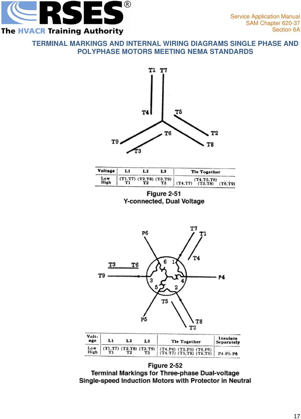
TERMINAL MARKINGS AND INTERNAL WIRING DIAGRAMS SINGLE PHASE AND POLYPHASE MOTORS MEETING NEMA STANDARDS
|
|
|
- Mitchell Powell
- 10 years ago
- Views:
Transcription
1 INTRODUCTION The following represents the most up-to-date information on motor terminal marking for proper connection to power source for all alternating current motors manufactured in accordance with standards adopted by the National Electrical Manufacturers Association. In addition, this section contains important data covering internal wiring to motor terminals which will prove invaluable to the Refrigeration Service Engineer in solving motor problems. The source of this information is Part 2 of the NEMA Standards Publication, for which reprint permission was granted RSES by the National Electrical Manufacturers' Association. MG LOCATION OF TERMINAL MARKINGS Terminal markings shall be placed on or directly adjacent to terminals to which connections must be made from outside circuits or from auxiliary devices which must be disconnected for shipment. Wherever specified, color coding may be used instead of the usual letter and numeral marking.* MG TERMINAL MARKINGS A combination of capital letters or symbols and an arabic numeral shall be used to indicate the character or function of the windings which are brought to the terminal.* The following letters and symbols shall be used for motors and generators and their auxiliary devices when they are included within or mounted on the machine.* Resistance (shunt field adjusting) V1, V2, V3, etc. Shunt braking resistor DR1, DR2, DR3, DR4, etc. Space heaters H1, H2, H3, H4, etc. Stator T1, T2, T3, T4, etc. Starting switch K. Terminal protector P1, P2, P3, P4, etc. Equalizing lead = (equality sign). Neutral connection Terminal letter with numeral 0. For the significance of the arabic numeral, see MG for alternating-current machines. For alternating-current machines only. Armature A1, A2, A3, A4, etc. Brake B1, B2, B3, B4, etc. Alternating-current rotor windings (collector rings) M1, M2, M3, M4, etc. Capacitor J1, J2, J3, J4, etc. Control signal lead attached to commutating winding C. 1

2 Dynamic braking resistor BR1, BR2, BR3, BR4, etc. Field (series) S1, S2, S3, S4, etc. Field (shunt) F1, F2, F3, F4, etc. Line L1, L2, L3, L4, etc. Magnetizing winding (for initial and maintenance magnetization and demagnetization of permanent magnetic fields) E1, E2, E3, E4, etc. (NOTE E1, E3, or other odd-numbered terminals should be attached to the positive terminal of the magnetizing power supply for magnetization and to the negative terminal for demagnetization.) Resistance (armature and miscellaneous) R1, R2, R3, R4, etc. * Approved as NEMA Standard Approved as Authorized Engineering Information Added as NEMA Standard ALTERNATING-CURRENT MOTORS AND GENERATORS MG Numerals on Terminals Of Alternating-Current Polyphase Machines A. SYNCHRONOUS MACHINES The numerals 1, 2, 3, etc., indicate the order in which the voltages at the terminals reach their maximum positive values (phase sequence) with clockwise shaft rotation when facing the connection end of the coil windings: hence, for counterclockwise shaft rotation (not standard) when facing the same end, the phase sequence will be 1, 3, 2. B. INDUCTION MACHINES Terminal markings of polyphase induction machines are not related to the direction of rotation. * Approved as NEMA Standard Approved as Authorized Engineering Information MG Definition Of Phase Sequence Phase sequence is the order in which the voltages successively reach their maximum positive values between terminals.* MG Phase Sequence The order of numerals on terminal leads does not necessarily indicate the phase sequence, but the phase sequence is determined by the direction of shaft rotation relative to the connection end of the coil winding. MG Direction Of Rotation Of Vectors Vector diagrams shall be shown so that advance in phase of one vector with respect to another is in the counterclockwise direction. 2
 Resistance (armature and miscellaneous) R1, R2, R3, R4, etc.")
3 See Fig in which vector 1 is 120 degrees in advance of vector 2 and the phase sequence is 1, 2, 3. (See MG )* MG Direction Of Rotation The standard direction of rotation for alternating generators is clockwise when facing the end of the machine opposite the drive.* The direction of rotation of a generator mounted as a part of an engine-generator set is usually counterclockwise when facing the end opposite the drive. The standard direction of rotation for all alternating-current single-phase motors, all synchronous motors, and all universal motors shall be counterclockwise when facing the end of the machine opposite the drive.* MG Reversal Of Rotation, Polarity And Phase Sequence Alternating-current generators driven counterclockwise when facing the connection end of the coil windings will generate without change in connections, but the terminal phase sequence will be 1, 3, 2. Synchronous condensers and synchronous motors may be operated with counterclockwise shaft rotation viewed from the connection end of the coil windings by connecting them to leads in which the phase sequence is 1, 2, 3, in the following manner: Power leads... 1, 2, 3 Machine terminals...1, 3, 2 ALTERNATING-CURRENT GENERATORS AND SYNCHRONOUS MOTORS MG Connections And Terminal Markings Alternating-Current Generators And Synchronous Motors One, Two, And Three Phase The alternating-current windings of three-phase alternating-current generators and synchronous motors shall have terminal markings as given in MG for three-phase single-speed induction motors.* The alternating-current windings of two-phase alternating-current generators and synchronous motors shall have terminal markings as given in MG for two-phase single-speed induction motors.* The alternating-current windings of single-phase alternating-current generators and synchronous motors shall have terminal markings as given in Fig * 3

4 The terminal markings of direct-current field windings shall be F1 and F2.* NOTE: See MG for terminal letters assigned to different types of windings and MG for the significance of the numerals. SINGLE-PHASE MOTORS MG General A. DUAL VOLTAGE Regardless of type, when a single-phase motor is reconnectible series-parallel for dual voltage, the terminal marking shall be determined as follows:* For the purpose of assigning terminal markings, the main winding is assumed to be divided into two halves, and T1 and T2 should be assigned to one half and T3 and T4 to the other half.* For the purpose of assigning terminal markings, the auxiliary winding (if present) is assumed to be divided into two halves, and T5 and T6 should be assigned to one half and T7 and T8 to the other half.* Polarities shall be established so that the standard direction of rotation (counterclockwise facing the end opposite the drive) is obtained when the main winding terminal T4 and the auxiliary winding terminal T5 are joined or when an equivalent circuit connection is made between the main and auxiliary winding.* The terminal marking arrangement is shown diagrammatically in Fig * 4

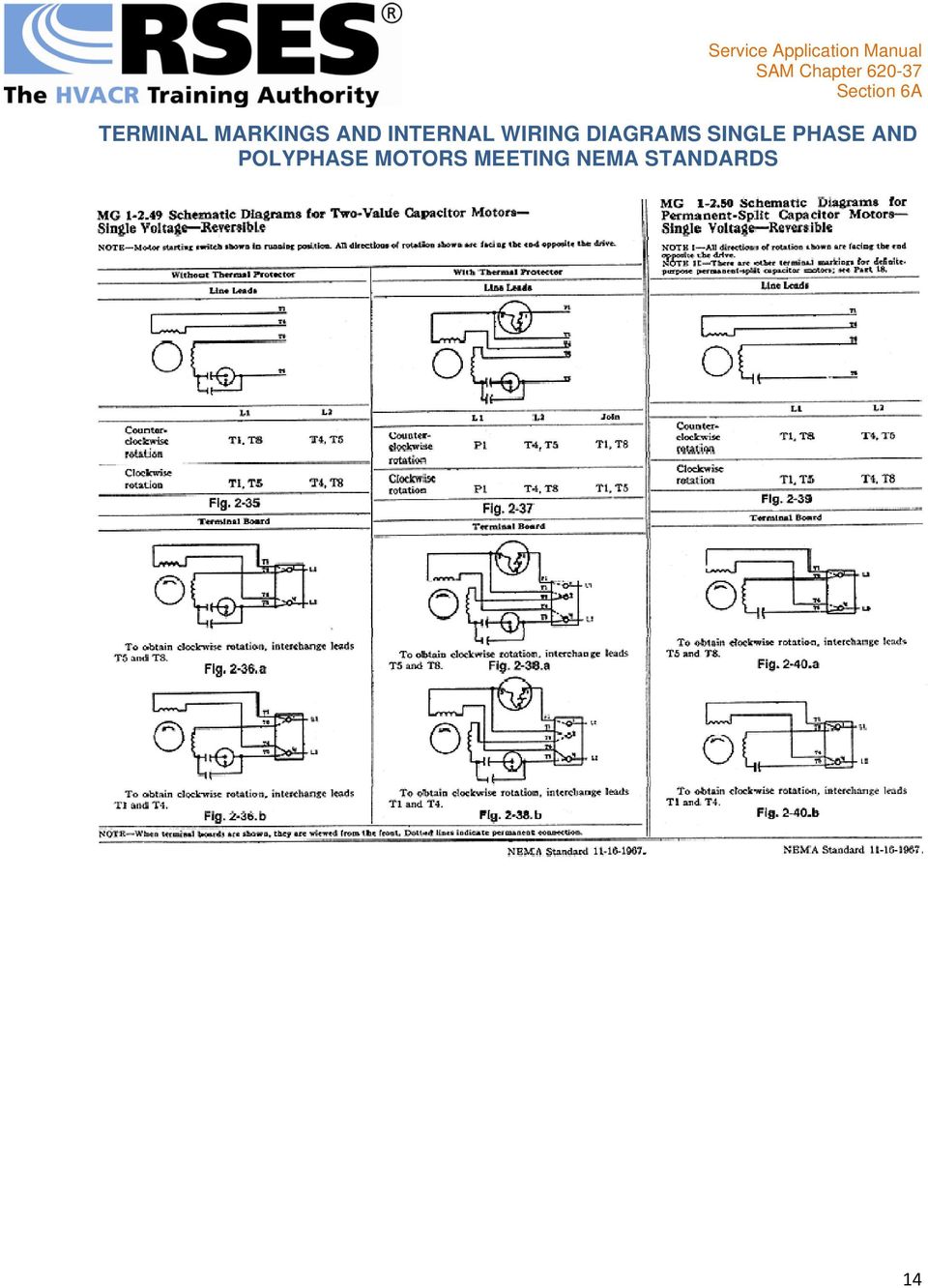
5 B. SINGLE VOLTAGE If a single-phase motor is single voltage or if either winding is intended for only one voltage, the terminal marking shall be determined as follows.* T1 and T4 shall be assigned to the main winding and T5 and T8 to the auxiliary winding (if present) with the polarity arrangement such that the standard direction of rotation is obtained if T4 and T5 are joined to one line and T1 and T8 to the other.* The terminal marking arrangement is shown diagrammatically in Fig * 5

6 NOTE: It has been found to be impracticable to follow this standard for the terminal markings of some definite-purpose motors. See Part 18. NOTE: No general standards have been developed for terminal markings of multispeed motors because of the great variety of methods employed to obtain multiple speeds. MG Terminal Markings Identified By Color When single-phase motors use lead colors instead of letter and number markings to identify the leads, the color assignment shall be determined from the following:* T1 Blue T2 White T3 Orange T4 Yellow T5 Black T8 Red P1 No color assigned P2 Brown NOTE: It has been found to be impracticable to follow this standard for the lead markings of some definite-purpose motors. See Part 18. MG Auxiliary Devices Within Motor The presence of an auxiliary device or devices, such as a capacitor, starting switch, terminal protector, etc., permanently connected in series between the motor terminal and the part of the winding to which it ultimately connects shall not affect the marking unless a terminal is provided at the junction.* Where a terminal is provided at the junction, the terminal marking of this junction shall be determined by the part of the winding to which it is connected. Any other terminals connected to this auxiliary device shall be identified by a letter indicating the auxiliary device within the motor to which the terminal is connected.* MG Auxiliary Devices External To Motor Where the capacitors, resistors, inductors, transformers or other auxiliary devices are housed separately from the motor, the terminal markings shall be those established for the device.* 6

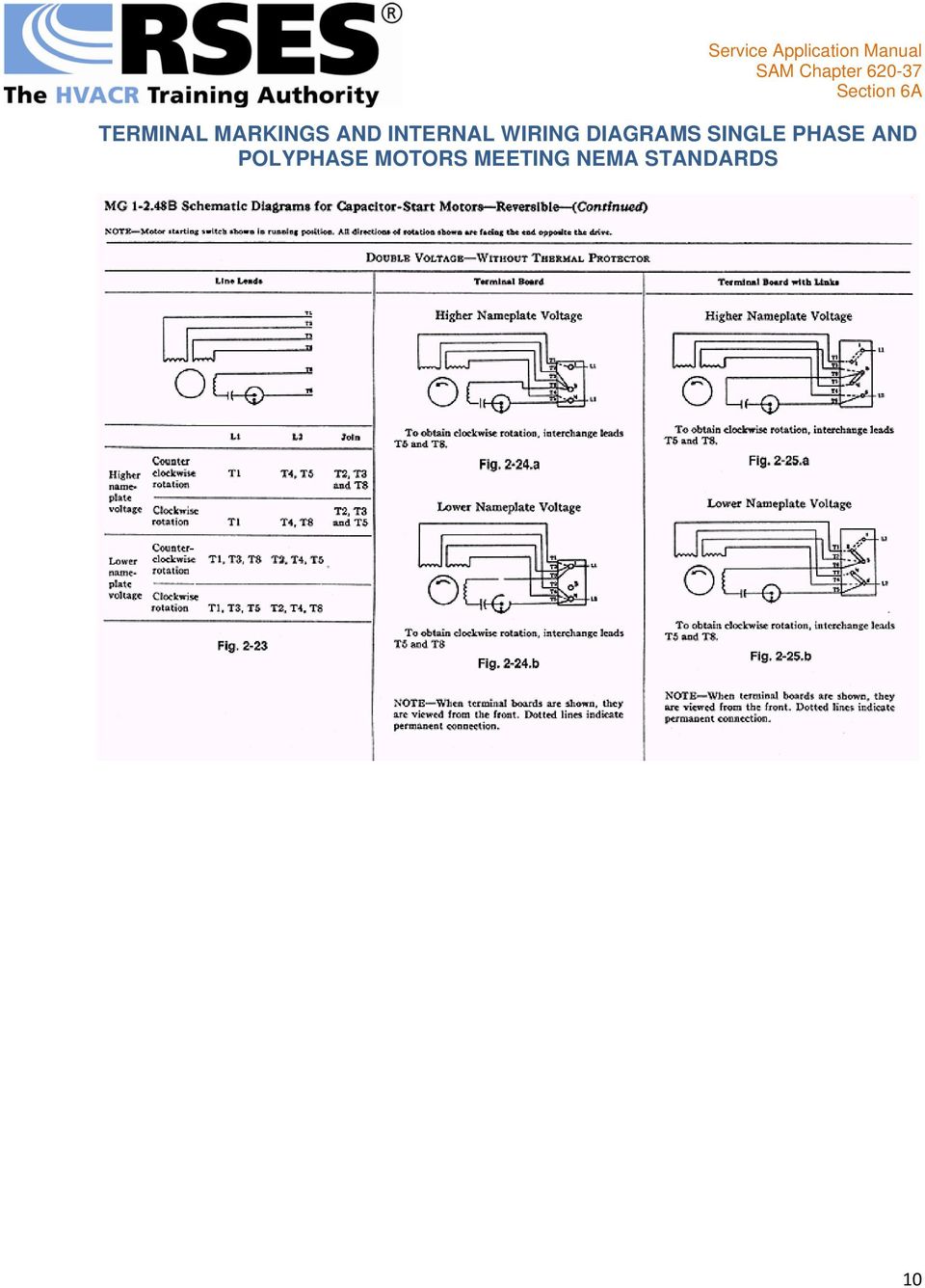
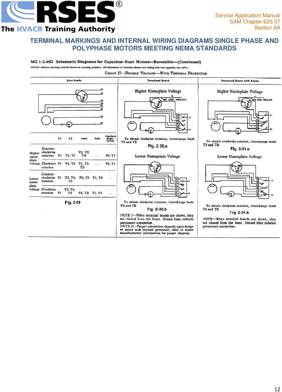
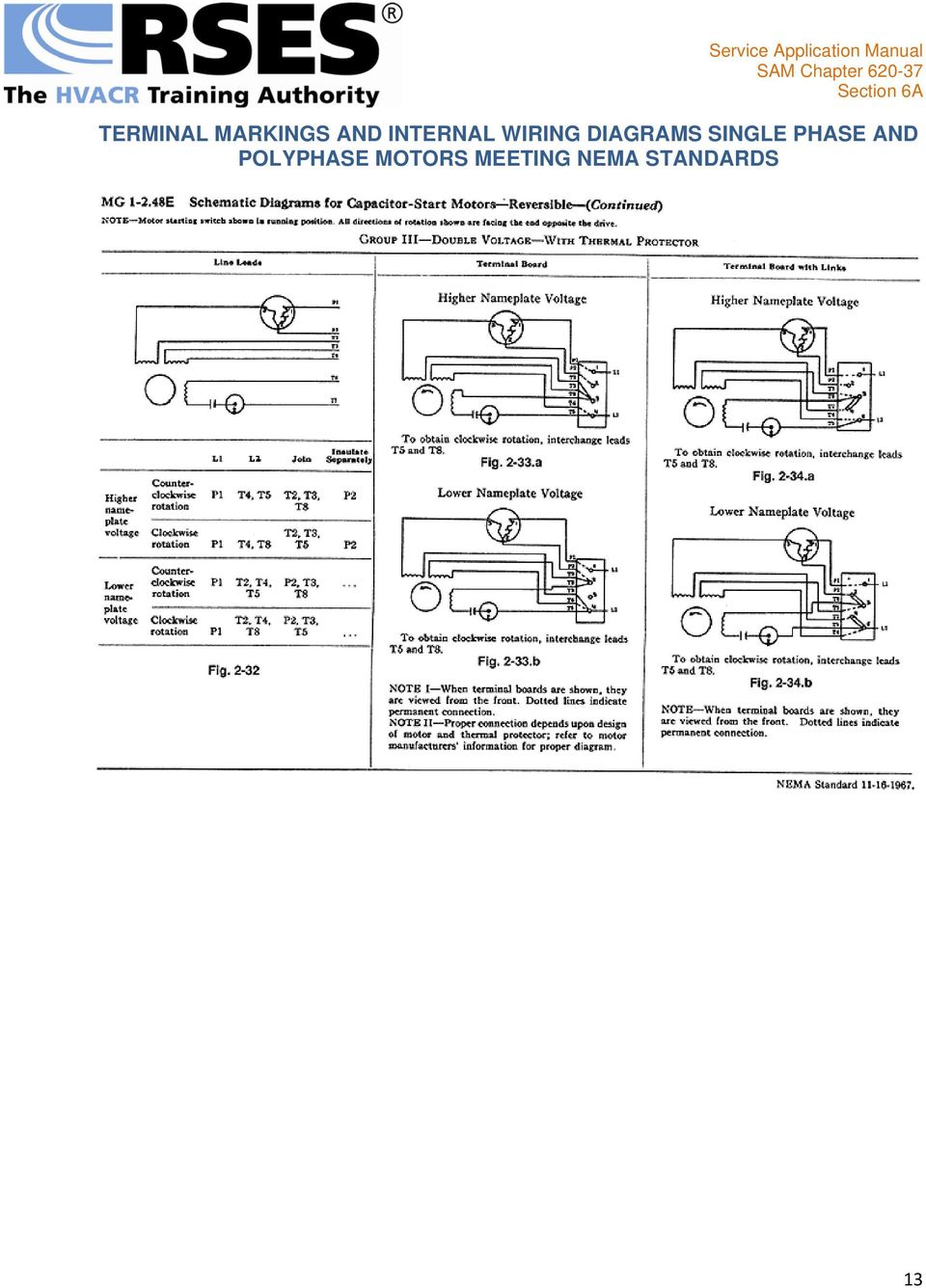
7 MG Marking Of Rigidly-Mounted Terminals On a terminal board, the identification of rigidly-mounted terminals shall be either by marking on the terminal board or by means of a diagram attached to the machine. When all windings are permanently connected to rigidly mounted terminals, these terminals may be identified in accordance with the terminal markings specified in this article. When windings are not permanently attached to rigidly-mounted terminals on a terminal board, the rigidly-mounted terminals shall be identified by numbers only, and the identification need not coincide with that of the terminal leads connected to the rigidly-mounted terminals.* MG Internal Auxiliary Devices Permanently Connected To Rigidly-Mounted Terminals If the motor design is such that the starting switch, terminal protector or other auxiliary device is permanently connected to a rigidly mounted terminal, some variation from the connection arrangements illustrated in MG through MG will be required. However, any variations shall be based on the provisions of MG * MG General Principles For Terminal Markings For Single-Phase Motors The terminal marking and connection procedure given in MG through MG and in the schematic diagrams which follow are based on the following principles: A. FIRST PRINCIPLE The main winding of a single-phase motor is designated by T1, T2, T3 and T4 and the auxiliary winding by T5, T6, T7 and T8 to distinguish it from a quarter-phase motor which uses odd numbers for one phase and even numbers for the other phase. B. SECOND PRINCIPLE By following the first principle, it follows that odd-to-odd numbered terminals of each winding are joined for lower voltage (parallel) connection and odd-to-even numbered terminals of each winding are joined for higher voltage (series) connection. C. THIRD PRINCIPLE The rotor of a single-phase motor is represented by a circle, even though there are no external connections to it. It also serves to distinguish the single-phase motor schematic diagram from that of the quarter-phase motor in which the rotor is never represented. * Approved as NEMA Standard Approved as Authorized Engineering Information

8 8

9 9

10 10
11 11

12 12
13 13
14 14
15 POLYPHASE INDUCTION MOTORS MG General Principles For Terminal Markings For Polyphase Induction Motors A. The markings of the terminals of a motor serve their purpose best if they indicate the electrical relations between the several circuits within the motor. The windings of a motor are seldom accessible, and the arrangement of the terminal numbers varies with the combinations of connections which are required. However, if a definite system of numbering is used, the marking of the terminals may be made to tell the exact relations of the windings within the motor. As far as practicable, MG and MG are formulated to embody such a system, which system employs as one of its fundamental points a clockwise rotating spiral with T1 at the outer end and finishing with the highest number at its inner end as a means for determining the sequence of the numerals. See Fig

16 The numbering of the terminals on polyphase induction motors does not imply standardization of the direction of rotation of the motor shaft. B. For three-phase motors having two synchronous speeds obtained from a reconnectible winding, it is undesirable to adhere to the clockwise system of numbering for all terminals as this would cause the motor to run with clockwise shaft rotation on one speed and counterclockwise on the other speed if the power lines are connected to each set of terminals in the same sequence. This feature may be considered an advantage as a winding with part of its terminals following a clockwise sequence and part following a counterclockwise sequence can be recognized immediately as a two-speed motor with a reconnectible winding. C. For two-phase motors, the terminal markings are such that all odd numbers are in one phase and all even numbers are in the other phase. The markings of all motors except those for two speed motors using a single reconnectible winding are based, as are three-phase windings, on a clockwise spiral system of rotation in the sequence of terminal numbering. MG Terminal Markings For Three-Phase Single-Speed Induction Motors The terminal markings for three-phase singlespeed induction motors shall be as shown in Fig. 2-51, 2-52, 2-53 and

17 17
18 These terminal markings were developed in accordance with the following procedure which shall be used in developing terminal markings for other combinations of motor stator circuits:* 18

19 A. FIRST A schematic vector diagram should be drawn showing an inverted Y connection with the individual circuits in each phase arranged for series connection with correct polarity relation of circuits. The diagram for two circuits per phase, for example, is as shown in Fig * B. SECOND Starting with T1 at the outside and top of the diagram, the ends of the circuit shall be numbered consecutively in a clockwise direction proceeding on a spiral towards the center of the diagram. For two circuits per phase, for example, the terminals are marked as shown in Fig * C. THIRD A schematic vector diagram shall be drawn showing the particular interconnection of circuits for the motor under consideration, and the terminal markings determined in accordance with par. A and B shall be arranged to give the correct polarity relation of circuits. For example, if the winding shown in Fig is to be connected with two circuits in multiple per phase, the diagram and markings shall be as shown in Fig * 19

20 D. FOURTH The highest numbers shall be dropped and only the lowest number shall be retained where two or more terminals are permanently connected together. For example, if the winding shown in Fig is to have the two circuits in each phase permanently connected together with three line leads and three neutral leads brought out, the terminal markings shall be as shown in Fig. 2-48, 20

21 or, if the winding shown in Fig is to be arranged for either a series or a multiple connection with the neutral point brought out, the vector diagram and terminal markings shall be as shown in Fig * E. FIFTH Where the ends of three coils are connected together to form a permanent neutral, the terminal markings of the three leads so connected shall be dropped. If the neutral point is brought out, it shall always be marked T0. See Fig * F. SIXTH If a winding is to be delta-connected, the inverted Y diagram (Fig. 2-45) shall be rotated 30 degrees counterclockwise. T1 shall be assigned to the outer end of the top leg and the balance of the numbering shall be in accordance with MG and Fig A schematic delta shall then be constructed in which the T1 leg of the rotated Y becomes the right-hand side of the delta, the T2 leg becomes the bottom (horizontal) side, and the T3 leg becomes the left side of the delta. MG shall be applied insofar as it applies to a delta connection. See Fig * 21
22 * Approved as NEMA Standard Approved as Authorized Engineering Information MG Terminal Markings For Y-And Delta-Connected Dual-Voltage Motors Fig through 2-54 illustrate the application of MG in determining terminal markings of Y-and delta-connected dual-voltage motors. MG Terminal Markings For Three-Phase Two-Speed Single-Winding Induction Motors The general principles for terminal markings for polyphase induction motors given in par. B of MG are not applicable to three-phase two-speed single-winding induction motors because, if followed and the terminals are connected in the same sequence, the direction of rotation at the two speeds will be different. MG Terminal Markings For Y-And Delta-Connected Two-Speed Single-Winding Motors The terminal markings for Y-and delta-connected two-speed single-winding three-phase induction motors shall be in accordance with Fig through
23 23
24 24
25 The neutral terminal, if brought out, shall be marked T0*. MG Terminal Markings For Three-Phase Induction Motors Having Two Or More Synchronous Speeds Obtained From Two Or More Independent Windings A. EACH INDEPENDENT WINDING GIVING ONE SPEED The winding giving the lowest speed shall take the same markings as determined from MG for the particular winding used. The terminal markings for the higher speed windings shall be obtained by adding 10, 20, or 30, etc., to the terminal markings as determined from MG for the particular winding used, the sequences being determined by progressing each time to the next higher speed. The terminal markings for a three-speed motor using three windings are given in Fig * 25
26 B. EACH INDEPENDENT WINDING RECONNECTIBLE TO GIVE, TWO SYNCHRONOUS SPEEDS 1. First Vector diagrams of the windings to be used shall be drawn and each winding given the terminal markings shown in MG * 2. Second No change shall be made in any of the terminal markings of the winding giving the lowest speed, irrespective of whether the other speed obtained from this winding is an intermediate or the highest speed.* 3. Third Ten shall be added to all terminal markings of the winding giving the next higher speed, and an additional 10 shall be added to all the terminal markings for each consecutively higher speed winding. The terminal markings for a four-speed motor using two windings are given in Fig * 26
27 C. TWO OR MORE INDEPENDENT WINDINGS AT LEAST ONE, OF WHICH GIVES ONE SYNCHRONOUS SPEED AND THE OTHER WINDING GIVES TWO SYNCHRONOUS SPEEDS 1. First Each winding shall be given the markings determined in accordance with MG or MG * 2. Second No change shall be made in any of the terminal markings of the winding giving the lowest speed.* 3. Third Ten shall be added to all terminal markings of the winding giving the next higher speed, and an additional 10 shall be added to all the terminal markings for each consecutively higher speed winding. A typical terminal marking for a three-speed motor using two windings where one of the windings is used for the high speed only is given in Fig * 27
28 NOTE: If, under any of the provisions of this standard, the addition of 10, 20, 30, etc., to the basic terminal markings causes a duplication of markings due to more than nine leads being brought out on any one winding, then 20, 40, 60, etc., should be added instead of 10, 20, 30, etc., to obtain the markings for the higher speeds. NOTE: The illustrative figures in this standard apply when all leads are brought out on the same end of the motor. When one or more of the windings have some leads brought out on one end of the motor and some on the other end, the rotation of the terminal markings for leads brought out on one end may be shown on the diagram as shown in the illustrative figures, and the terminal markings for those brought out on the opposite end may be shown reversed in rotation. When diagrams use this reversed rotation of markings, an explanatory note should be included for the benefit of the control manufacturer and user to inform them that, when L1, L2 and L3 are connected to any winding with the same sequence of numbers (T1, T2, T3; or T4, T5, T6; or T11, T12, T13, etc.), the shaft rotation will be the same. * Approved as NEMA Standard Approved as Authorized Engineering Information
29 MG Two-Phase Single-Speed Induction Motors A. FIRST A schematic vector diagram shall be drawn showing a plus connection with the individual circuits in each phase arranged for series connection with correct polarity relation of circuits. The diagram for three circuits per phase, for example, is as shown in Fig * B. SECOND Starting with T1 at the outside and top of the diagram, the ends of the circuit shall be numbered consecutively in a clockwise direction proceeding on a spiral towards the center of the diagram. For three circuits per phase, for example, the terminals are marked as shown in Fig * 29
30 C. THIRD A schematic vector diagram shall be drawn showing the particular interconnection of circuits for the motor under consideration and the terminal markings as determined in accordance with par. A and B shall be arranged to give correct polarity relation of circuits. If the winding in Fig is to be connected with three circuits in multiple per phase, the diagram and markings shall be as shown in Fig * D. FOURTH The highest numbers shall be dropped and only the lowest number shall be retained where two or more terminals are permanently connected together. If the winding shown in Fig is to have the three circuits in each phase permanently connected together with a single line lead brought out from each end of each phase, the terminal markings shall be as shown in Fig * 30
31 E. FIFTH If a two-phase three-wire power supply is used, T3 and T4 shall be connected together and only the T3 marking shall be retained for the common wire.* F. SIXTH If the two phases are to be interconnected at the midpoint to connect to a two-phase five-wire system, the midpoint terminal shall be marked T0.* * Approved as NEMA Standard Approved as Authorized Engineering Information MG Two-Speed Single-Winding Two-Phase Induction Motors Since there is only one commonly used winding arrangement for these motors, no attempt has been made to develop a method for determining terminal markings. The schematic diagram for the commonly used winding arrangement shall be as shown in Fig * 31
32 MG Terminal Markings For Two-Phase Induction Motors Having Two Or More Synchronous Speeds From Two Or More Independent Windings A. EACH INDEPENDENT WINDING GIVING MORE THAN ONE SPEED The winding giving the lowest speed shall take the same terminal markings as determined from MG for the particular winding used. The terminal markings for the higher speed windings shall be obtained by adding 10, 20, or 30, etc., to the terminal markings determined from MG for the particular winding used, the sequences being determined by progressing each time to the next higher speed. The terminal markings for a two-speed motor using two single-speed windings shall be as shown in Fig * B. EACH INDEPENDENT WINDING RECONNECTIBLE TO GIVE TWO SYNCHRONOUS SPEEDS 1. First Each winding shall be given the terminal markings shown in Fig of MG * 2. Second No change shall be made in any of the terminal markings of the winding giving the lowest speed irrespective of whether the other speed obtained from this winding is an intermediate or the highest speed.* 3. Third Ten shall be added to terminal markings of the winding giving the next higher speed and an additional 10 shall be added to all the terminal markings for each consecutively higher speed winding. The terminal markings for a four-speed motor using two windings shall be as shown in Fig * 32
33 C. TWO INDEPENDENT WINDINGS AT LEAST ONE OF WHICH GIVES ONE SYNCHRONOUS SPEED AND THE OTHER WINDING GIVES TWO SYNCHRONOUS SPEEDS NOTE: 1. First Each winding shall be given the markings determined in accordance with MG or MG * 2. Second No change shall be made in any of the terminal markings of the winding giving the lowest speed.* 3. Third Ten shall be added to all terminal markings of the winding giving the next higher speed, and an additional 10 shall be added to all the terminal markings of each consecutively higher speed winding. The terminal markings for a three-speed motor using two windings shall be as shown in Fig * If, under any of the provisions of this standard, the addition of 10, 20, 30, etc., to the basic terminal markings causes a duplication of markings due to more than nine leads being brought out on any one winding, then 20, 40, 60, etc. should be added instead of 10, 20, 30, etc., to obtain the markings for the higher speeds. MG Terminal Markings Of The Rotors Of Wound-Rotor Induction Motors See Fig a and 2-71.b.* * Approved as NEMA Standard Approved as Authorized Engineering Information
34 34
35 Copyright 1967, 2009, By Refrigeration Service Engineers Society. 35
Unit 33 Three-Phase Motors
 Unit 33 Three-Phase Motors Objectives: Discuss the operation of wound rotor motors. Discuss the operation of selsyn motors. Discuss the operation of synchronous motors. Determine the direction of rotation
2. A conductor of length 2m moves at 4m/s at 30 to a uniform magnetic field of 0.1T. Which one of the following gives the e.m.f. generated?
 Extra Questions - 2 1. A straight length of wire moves through a uniform magnetic field. The e.m.f. produced across the ends of the wire will be maximum if it moves: a) along the lines of magnetic flux
SECTION 4 ELECTRIC MOTORS UNIT 17: TYPES OF ELECTRIC MOTORS
 SECTION 4 ELECTRIC MOTORS UNIT 17: TYPES OF ELECTRIC MOTORS UNIT OBJECTIVES After studying this unit, the reader should be able to Describe the different types of open single-phase motors used to drive
Three phase circuits
 Three phase circuits THREE PHASE CIRCUITS THREE-PHASE ADVANTAGES 1. The horsepower rating of three-phase motors and the kva rating of three-phase transformers are 150% greater than single-phase motors
Equipment: Power Supply, DAI, Wound rotor induction motor (8231), Electrodynamometer (8960), timing belt.
, Electrodynamometer (8960), timing belt.") Lab 13: Wound rotor induction motor. Objective: to examine the construction of a 3-phase wound rotor induction motor; to understand exciting current, synchronous speed and slip in this motor; to determine
Lab 13: Wound rotor induction motor. Objective: to examine the construction of a 3-phase wound rotor induction motor; to understand exciting current, synchronous speed and slip in this motor; to determine
Lab 8: DC generators: shunt, series, and compounded.
 Lab 8: DC generators: shunt, series, and compounded. Objective: to study the properties of DC generators under no-load and full-load conditions; to learn how to connect these generators; to obtain their
TERMINAL MARKINGS AND CONNECTIONS PART WINDING START
 TERMINAL MARKINGS AND CONNECTIONS PART WINDING START NEMA NOMENCLATURE 6 LEADS 7 7 3 9 8 Delta 3 9 8 Wye OPER. 9 MODE L L L3 OPEN 7 START 3 7,8,9 T T T3 T7 T8 T9 RUN,7,8 3,9 3 8 MOTOR LEADS 3 7 Double
DIRECT CURRENT GENERATORS
 DIRECT CURRENT GENERATORS Revision 12:50 14 Nov 05 INTRODUCTION A generator is a machine that converts mechanical energy into electrical energy by using the principle of magnetic induction. This principle
Permanent Magnet Motor Kit, Magnetic Reed Type. (SKY-ReedMotorKit) Instructions
 Instructions") Permanent Magnet Motor Kit, Magnetic Reed Type (SKY-ReedMotorKit) Instructions This kit contains powerful permanent magnets. Exercise caution when handling them as they can pull on iron tools and snap
Permanent Magnet Motor Kit, Magnetic Reed Type (SKY-ReedMotorKit) Instructions This kit contains powerful permanent magnets. Exercise caution when handling them as they can pull on iron tools and snap
Cam switches. Page. Overview 4-2. ON-OFF switches, main switches, maintenance switches 4-3. Changeover switches, reversing switches 4-5
 Eaton Wiring Manual / Page Overview - ON-OFF switches, main switches, maintenance switches - Changeover switches, reversing switches - (Reversing) star-delta switches - Multi-Speed Switches - Interlock
C Standard AC Motors
 C Standard AC Standard AC C-1 Overview, Product Series... C-2 Constant... C-9 C-21 C-113 Reversible C-147 Overview, Product Series Constant Reversible Electromagnetic Brake C-155 Electromagnetic Brake
Comparison of NEMA and IEC schematic diagrams
 Cross-Reference MZ081001EN Comparison of NEMA and IEC schematic diagrams General With the increasing emphasis on globalization, many industries are now looking to all parts of the world to produce, market,
Motor Fundamentals. DC Motor
 Motor Fundamentals Before we can examine the function of a drive, we must understand the basic operation of the motor. It is used to convert the electrical energy, supplied by the controller, to mechanical
SEWER CHEWER Wastewater / Sludge Grinder Submersible Gearmotor
 INSTALLATION, OPERATION AND MAINTENANCE MANUAL For SEWER CHEWER Wastewater / Sludge Grinder Submersible Gearmotor Yeomans Chicago Corporation 3905 Enterprise Court P.O. Box 6620 Aurora, IL 60598-0620 Phone:
COMPUTER AIDED ELECTRICAL DRAWING (CAED) 10EE65
 10EE65") COMPUTER AIDED ELECTRICAL DRAWING (CAED) EE Winding Diagrams: (i) DC Winding diagrams (ii) AC Winding Diagrams Terminologies used in winding diagrams: Conductor: An individual piece of wire placed in the
COMPUTER AIDED ELECTRICAL DRAWING (CAED) EE Winding Diagrams: (i) DC Winding diagrams (ii) AC Winding Diagrams Terminologies used in winding diagrams: Conductor: An individual piece of wire placed in the
What Is Regeneration?
 What Is Regeneration? Braking / Regeneration Manual Regeneration Overview Revision 1.0 When the rotor of an induction motor turns slower than the speed set by the applied frequency, the motor is transforming
Synchronous motor. Type. Non-excited motors
 Synchronous motor A synchronous electric motor is an AC motor in which the rotation rate of the shaft is synchronized with the frequency of the AC supply current; the rotation period is exactly equal to
8 Speed control of Induction Machines
 8 Speed control of Induction Machines We have seen the speed torque characteristic of the machine. In the stable region of operation in the motoring mode, the curve is rather steep and goes from zero torque
AC Generators and Motors
 AC Generators and Motors Course No: E03-008 Credit: 3 PDH A. Bhatia Continuing Education and Development, Inc. 9 Greyridge Farm Court Stony Point, NY 10980 P: (877) 322-5800 F: (877) 322-4774 [email protected]
EET272 Worksheet Week 9
 EET272 Worksheet Week 9 answer questions 1-5 in preparation for discussion for the quiz on Monday. Finish the rest of the questions for discussion in class on Wednesday. Question 1 Questions AC s are becoming
Preview of Period 16: Motors and Generators
 Preview of Period 16: Motors and Generators 16.1 DC Electric Motors What causes the rotor of a motor to spin? 16.2 Simple DC Motors What causes a changing magnetic field in the simple coil motor? 16.3
Three-phase AC circuits
 Three-phase AC circuits This worksheet and all related files are licensed under the Creative Commons Attribution License, version 1.0. To view a copy of this license, visit http://creativecommons.org/licenses/by/1.0/,
..OR How To Protect your 3-Phase Equipment Investment with 3-Phase Monitors from Time Mark...
 ..OR How To Protect your 3-Phase Equipment Investment with 3-Phase Monitors from Time Mark... TIME MARK CORPORATION 11440 EAST PINE STREET TULSA, OK 74116 USA tel 918 438-1220 fax 918 437-7584 www.time-mark.com
Understanding the Alternator
 http://www.autoshop101.com THIS AUTOMOTIVE SERIES ON ALTERNATORS HAS BEEN DEVELOPED BY KEVIN R. SULLIVAN PROFESSOR OF AUTOMOTIVE TECHNOLOGY AT SKYLINE COLLEGE SAN BRUNO, CALIFORNIA ALL RIGHTS RESERVED
AND8008/D. Solid State Control Solutions for Three Phase 1 HP Motor APPLICATION NOTE
 Solid State Control Solutions for Three Phase 1 HP Motor APPLICATION NOTE INTRODUCTION In all kinds of manufacturing, it is very common to have equipment that has three phase motors for doing different
1. The diagram below represents magnetic lines of force within a region of space.
 1. The diagram below represents magnetic lines of force within a region of space. 4. In which diagram below is the magnetic flux density at point P greatest? (1) (3) (2) (4) The magnetic field is strongest
ABB ! CAUTION. Type COQ Negative Sequence Generator Relay. (50/60 Hertz) 41-161J. Instruction Leaflet
 41-161J. Instruction Leaflet") ABB Instruction Leaflet 41-161J Effective: May 1997 Supersedes I.L. 41-161H Dated July 1984 ( ) Denotes Change Since Previous Issue Type COQ Negative Sequence Generator Relay (50/60 Hertz)! CAUTION Before
ABB Instruction Leaflet 41-161J Effective: May 1997 Supersedes I.L. 41-161H Dated July 1984 ( ) Denotes Change Since Previous Issue Type COQ Negative Sequence Generator Relay (50/60 Hertz)! CAUTION Before
8022-0E Motor Winding Kit
 8022-0E Motor Winding Kit LabVolt Series Datasheet Festo Didactic en 220 V - 60 Hz 06/2016 Table of Contents General Description 2 Optional Equipment Required to Operate the Rotating Machines 3 Features
ELECTRICAL ENGINEERING Vol. III - Induction Motor and Self-Excited Induction Generator - Tze-Fun Chan
 INDUCTION MOTOR AND SELFEXCITED INDUCTION GENERATOR TzeFun Chan The Hong Kong Polytechnic University, Hung Hom, Kowloon, Hong Kong, China Keywords: threephase induction motor, singlephase induction motor,
Chapter 5. Components, Symbols, and Circuitry of Air-Conditioning Wiring Diagrams
 Chapter 5 Components, Symbols, and Circuitry of Air-Conditioning Wiring Diagrams Objectives Upon completion of this course, you will be able to: Explain what electrical loads are and their general purpose
Chen. Vibration Motor. Application note
 Vibration Motor Application note Yangyi Chen April 4 th, 2013 1 Table of Contents Pages Executive Summary ---------------------------------------------------------------------------------------- 1 1. Table
Motors and Generators
 Motors and Generators Electro-mechanical devices: convert electrical energy to mechanical motion/work and vice versa Operate on the coupling between currentcarrying conductors and magnetic fields Governed
DHANALAKSHMI COLLEGE OF ENGINEERING DEPARTMENT OF ELECTRICAL AND ELECTRONICS ENGINEERING EE2302 - ELECTRICAL MACHINES II UNIT-I SYNCHRONOUS GENERATOR
 1 DHANALAKSHMI COLLEGE OF ENGINEERING DEPARTMENT OF ELECTRICAL AND ELECTRONICS ENGINEERING Constructional details Types of rotors EE2302 - ELECTRICAL MACHINES II UNIT-I SYNCHRONOUS GENERATOR PART A 1.
Three-Phase AC Power Circuits
 Electricity and New Energy Three-Phase AC Power Circuits Student Manual 86360-F0 Order no.: 86360-00 Revision level: 10/2014 By the staff of Festo Didactic Festo Didactic Ltée/Ltd, Quebec, Canada 2010
NO LOAD & BLOCK ROTOR TEST ON THREE PHASE INDUCTION MOTOR
 INDEX NO. : M-142 TECHNICAL MANUAL FOR NO LOAD & BLOCK ROTOR TEST ON THREE PHASE INDUCTION MOTOR Manufactured by : PREMIER TRADING CORPORATION (An ISO 9001:2000 Certified Company) 212/1, Mansarover Civil
13 ELECTRIC MOTORS. 13.1 Basic Relations
 13 ELECTRIC MOTORS Modern underwater vehicles and surface vessels are making increased use of electrical actuators, for all range of tasks including weaponry, control surfaces, and main propulsion. This
Induction Motor Theory
 PDHonline Course E176 (3 PDH) Induction Motor Theory Instructor: Jerry R. Bednarczyk, P.E. 2012 PDH Online PDH Center 5272 Meadow Estates Drive Fairfax, VA 22030-6658 Phone & Fax: 703-988-0088 www.pdhonline.org
Automatic Voltage Regulator User s Manual
 Resp. dept. R&D We reserve all rights in this document and in the information contained therein. Reproduction, use or disclosure to third parties without express authority is strictly forbidden. Copyright
Equipment: Power Supply, DAI, Synchronous motor (8241), Electrodynamometer (8960), Tachometer, Timing belt.
, Electrodynamometer (8960), Tachometer, Timing belt.") Lab 9: Synchronous motor. Objective: to examine the design of a 3-phase synchronous motor; to learn how to connect it; to obtain its starting characteristic; to determine the full-load characteristic of
Lab 9: Synchronous motor. Objective: to examine the design of a 3-phase synchronous motor; to learn how to connect it; to obtain its starting characteristic; to determine the full-load characteristic of
Principles and Working of DC and AC machines
 BITS Pilani Dubai Campus Principles and Working of DC and AC machines Dr Jagadish Nayak Constructional features BITS Pilani Dubai Campus DC Generator A generator consists of a stationary portion called
Principles of Adjustable Frequency Drives
 What is an Adjustable Frequency Drive? An adjustable frequency drive is a system for controlling the speed of an AC motor by controlling the frequency of the power supplied to the motor. A basic adjustable
Faculty of Engineering. 48572 Power Circuit Theory. Lab 2 Three-Phase Circuits
 Faculty of Engineering Subject: 48572 ower ircuit Theory ssignment Number: 2 ssignment Title: Lab 2 Three-hase ircuits Tutorial Group: Students Name(s) and Number(s) Student Number Family Name First Name
Power measurement in balanced 3 phase circuits and power factor improvement. 1 Power in Single Phase Circuits. Experiment no 1
 Experiment no 1 Power measurement in balanced 3 phase circuits and power factor improvement 1 Power in Single Phase Circuits Let v = m cos(ωt) = cos(ωt) is the voltage applied to a R-L circuit and i =
IV. Three-Phase Induction Machines. Induction Machines
 IV. Three-Phase Induction Machines Induction Machines 1 2 3 4 5 6 7 8 9 10 11 12 13 Example 1: A 480V, 60 Hz, 6-pole, three-phase, delta-connected induction motor has the following parameters: R 1 =0.461
SPEED CONTROL SYSTEM
 SPEED CONTROL SYSTEM INDEX SPEED CONTROL MOTOR FEATURES 144 6W ( 70mm) 153 10W ( 70mm) 155 15W ( 80mm) 157 25W ( 80mm) 159 40W ( 90mm) 161 SPEED CONTROL W ( 90mm) 163 90W ( 90mm) 165 120W ( 90mm) 168 180W
The Ultimate Truck Stock Motor
 The Ultimate Truck Stock Motor What is a Rescue Motor? Universal Replacement Motor for Condenser Fan and Direct Drive Blower Applications Multi-Horsepower PSC Motors Flexible Mounting Options Permanent
Welcome to Linear Controls Quarterly Training
 Welcome to Linear Controls Quarterly Training Introduction to Power Generation Objectives Supply attendees with basic knowledge of power generators and voltage regulators and provide the fundamentals of
THREE PHASE CIRCUITS
 THREE PHASE CIRCUITS A. PREPARATION 1. Three Phase Voltages and Systems 2. The Determination of Phase Sequence 3. Blondel's Theorem and Its Consequences 4. References B. EXPERIMENT 1. Equipment List 2.
Impedance Matching. Using transformers Using matching networks
 Impedance Matching The plasma industry uses process power over a wide range of frequencies: from DC to several gigahertz. A variety of methods are used to couple the process power into the plasma load,
PHASE CONVERSION TECHNOLOGY OVERVIEW
 Dr. Larry Meiners, Ph.D. PHASE CONVERSION TECHNOLOGY OVERVIEW Introduction A wide variety of commercial and industrial electrical equipment requires three-phase power. Electric utilities do not install
Prof. Krishna Vasudevan, Prof. G. Sridhara Rao, Prof. P. Sasidhara Rao. x x. x x. Figure 10: Cross sectional view
 4 Armature Windings Main field Commutator & Brush Compole field haft v Compensating winding Armature winding Yoke Figure 10: Cross sectional view Fig. 10 gives the cross sectional view of a modern d.c.
EET272 Worksheet Week 8
 EET272 Worksheet Week 8 answer questions 1-5 in preparation for discussion for the quiz on Monday. Finish the rest of the questions for discussion in class on Wednesday. Question 1 Questions We will now
Speed Control Methods of Various Types of Speed Control Motors. Kazuya SHIRAHATA
 Speed Control Methods of Various Types of Speed Control Motors Kazuya SHIRAHATA Oriental Motor Co., Ltd. offers a wide variety of speed control motors. Our speed control motor packages include the motor,
Application Information Fully Integrated Hall Effect Motor Driver for Brushless DC Vibration Motor Applications
 Application Information Fully Integrated Hall Effect Motor Driver for Brushless DC Vibration Motor Applications By Shaun Milano Vibration motors are used in a variety of applications including mobile phone
FREQUENCY CONTROLLED AC MOTOR DRIVE
 FREQUENCY CONTROLLED AC MOTOR DRIVE 1.0 Features of Standard AC Motors The squirrel cage induction motor is the electrical motor motor type most widely used in industry. This leading position results mainly
Application Note AN- 1095
 Application Note AN- 1095 Design of the Inverter Output Filter for Motor Drives with IRAMS Power Modules Cesare Bocchiola Table of Contents Page Section 1: Introduction...2 Section 2 : Output Filter Design
DC Circuits (Combination of resistances)
") Name: Partner: Partner: Partner: DC Circuits (Combination of resistances) EQUIPMENT NEEDED: Circuits Experiment Board One Dcell Battery Wire leads Multimeter 100, 330, 1k resistors Purpose The purpose
Name: Partner: Partner: Partner: DC Circuits (Combination of resistances) EQUIPMENT NEEDED: Circuits Experiment Board One Dcell Battery Wire leads Multimeter 100, 330, 1k resistors Purpose The purpose
Servo Info and Centering
 Info and Centering A servo is a mechanical motorized device that can be instructed to move the output shaft attached to a servo wheel or arm to a specified position. Inside the servo box is a DC motor
UCI274C - Technical Data Sheet
 - Technical Data Sheet SPECIFICATIONS & OPTIONS STANDARDS Newage Stamford industrial generators meet the requirements of BS EN 60034 and the relevant section of other international standards such as BS000,
UCI274H - Technical Data Sheet
 - Technical Data Sheet SPECIFICATIONS & OPTIONS STANDARDS Newage Stamford industrial generators meet the requirements of BS EN 60034 and the relevant section of other international standards such as BS000,
LG Air Conditioning Multi F(DX) Fault Codes Sheet. Multi Split Units
 Fault Codes Sheet. Multi Split Units") Multi Split Units If there is a fault on any LG Multi unit, an Error mark is indicated on the display window of the indoor unit, wired-remote controller, and LED s of outdoor unit control board. A two
Multi Split Units If there is a fault on any LG Multi unit, an Error mark is indicated on the display window of the indoor unit, wired-remote controller, and LED s of outdoor unit control board. A two
THE LUCAS C40 DYNAMO & ITS ARMATURE.
 THE LUCAS C40 DYNAMO & ITS ARMATURE. H. Holden, March 2011. The Dynamo as a DC generating machine was used extensively in the pre- Alternator era, from the early 1900 s up to the late 1960 s and early
SHIP SERVICE GENERATORS (AC)
") CHAPTER 14 SHIP SERVICE GENERATORS (AC) INTRODUCTION All generators change mechanical energy into electrical energy. This is the easiest way to transfer power over distances. Fuel is used to operate the
CHAPTER 14 SHIP SERVICE GENERATORS (AC) INTRODUCTION All generators change mechanical energy into electrical energy. This is the easiest way to transfer power over distances. Fuel is used to operate the
SYNCHRONOUS MACHINES
 SYNCHRONOUS MACHINES The geometry of a synchronous machine is quite similar to that of the induction machine. The stator core and windings of a three-phase synchronous machine are practically identical
Welcome to this presentation on Switch Mode Drivers, part of OSRAM Opto Semiconductors LED Fundamentals series. In this presentation we will look at:
 Welcome to this presentation on Switch Mode Drivers, part of OSRAM Opto Semiconductors LED Fundamentals series. In this presentation we will look at: How switch mode drivers work, switch mode driver topologies,
How To Wire A Three Phase, Single Phase, Wye Transformer
 Three-Phase Transformers When more power is needed - three transformers can be tied together. This is called three-phase. Here s a simple way of comparing single-phase to threephase power. Single-Phase
Rotary Phase Converters
 FACTS from Ronk Electrical Industries, Inc. Bulletin 11981 Rotary Phase Converters ROTOVERTER Pat. No. 3,670,238 ROTO-CON Pat. No. 4,158,225 What are the ROTO-CON and ROTOVERTER power converters? The ROTO-CON
LG Air Conditioning - Universal Split Fault Codes Sheet. Universal Split Systems
 Universal Split Systems If there is a fault on any LG Universal unit, a two digit number will appear on the remote controllers led display. If the unit does not have a remote controller the fault will
Variable Transformers Product Design & Engineering Data
 Variable Transformers Product Design & Engineering Data Product Design & Engineering Data Type 1010B Cutaway General Information STACO ENERGY PRODUCTS CO. is a leading manufacturer of variable transformers,
Magnetic electro-mechanical machines
 Magnetic electro-mechanical machines Lorentz Force A magnetic field exerts force on a moving charge. The Lorentz equation: f = q(e + v B) f: force exerted on charge q E: electric field strength v: velocity
Lab 3 - DC Circuits and Ohm s Law
 Lab 3 DC Circuits and Ohm s Law L3-1 Name Date Partners Lab 3 - DC Circuits and Ohm s Law OBJECTIES To learn to apply the concept of potential difference (voltage) to explain the action of a battery in
Modeling and Simulation of a Novel Switched Reluctance Motor Drive System with Power Factor Improvement
 American Journal of Applied Sciences 3 (1): 1649-1654, 2006 ISSN 1546-9239 2006 Science Publications Modeling and Simulation of a Novel Switched Reluctance Motor Drive System with Power Factor Improvement
ET 332b Ac Electric Machines and Power Systems
 Instructor: Dr. Carl Spezia, PE Office: Engr. D110 Phone: 453-7839 E-mail: [email protected] ET 332b Ac Electric Machines and Power Systems Office Hours: 9:00 am - 10:00 am M-W-F 2:00 pm - 3:00 pm M-W-F
Simulation of Ungrounded Shipboard Power Systems in PSpice
 Simulation of Ungrounded Shipboard Power Systems in PSpice Haibo Zhang IEEE Student Member Karen L.Butler IEEE Member Power System Automation Lab Electrical Engineering Department Texas A&M University
Advance Electronic Load Controller for Micro Hydro Power Plant
 Journal of Energy and Power Engineering 8 (2014) 1802-1810 D DAVID PUBLISHING Advance Electronic Load Controller for Micro Hydro Power Plant Dipesh Shrestha, Ankit Babu Rajbanshi, Kushal Shrestha and Indraman
RADIO AGE. The Newsletter of the Mid-Atlantic Antique Radio Club. Atwater Kent Variometers, Variocouplers, and Related Devices
 RADIO AGE The Newsletter of the Mid-Atlantic Antique Radio Club Volume 30 December 2005 Number 12 Atwater Kent Variometers, Variocouplers, and Related Devices BY RAY THOMPSON AND LEIGH BASSETT 2005, RAY
Power Quality Paper #3
 The Effect of Voltage Dips On Induction Motors by: M D McCulloch 1. INTRODUCTION Voltage depressions caused by faults on the system affect the performance of induction motors, in terms of the production
DC Motor control Reversing
 January 2013 DC Motor control Reversing and a "Rotor" which is the rotating part. Basically there are three types of DC Motor available: - Brushed Motor - Brushless Motor - Stepper Motor DC motors Electrical
17. LIGHTS/INSTRUMENTS/SWITCHES
 17 SERVICE INFORMATION... 17-0 IGNITION SWITCH... 17-3 TROUBLESHOOTING... 17-0 STOP SWITCHES/HORN... 17-4 FUEL UNIT... 17-1 INSTRUMENTS... 17-4 HANDLEBAR SWITCHES... 17-2 HEADLIGHT/LIGHTS... 17-5 17 SERVICE
REPORT ON CANDIDATES WORK IN THE CARIBBEAN ADVANCED PROFICIENCY EXAMINATION MAY/JUNE 2008 ELECTRICAL AND ELECTRONIC TECHNOLOGY (TRINIDAD AND TOBAGO)
") CARIBBEAN EXAMINATIONS COUNCIL REPORT ON CANDIDATES WORK IN THE CARIBBEAN ADVANCED PROFICIENCY EXAMINATION MAY/JUNE 2008 ELECTRICAL AND ELECTRONIC TECHNOLOGY (TRINIDAD AND TOBAGO) Copyright 2008 Caribbean
CARIBBEAN EXAMINATIONS COUNCIL REPORT ON CANDIDATES WORK IN THE CARIBBEAN ADVANCED PROFICIENCY EXAMINATION MAY/JUNE 2008 ELECTRICAL AND ELECTRONIC TECHNOLOGY (TRINIDAD AND TOBAGO) Copyright 2008 Caribbean
Unit/Standard Number. High School Graduation Years 2010, 2011 and 2012
 1 Secondary Task List 100 SAFETY 101 Demonstrate an understanding of State and School safety regulations. 102 Practice safety techniques for electronics work. 103 Demonstrate an understanding of proper
SECTION 26 09 13 - POWER MONITOR FOR ELECTRICAL, STEAM CONDENSATE, AND WATER PART I - GENERAL
 SECTION 26 09 13 - POWER MONITOR FOR ELECTRICAL, STEAM CONDENSATE, AND WATER PART I - GENERAL 1.1 SUMMARY A. This section describes the requirements for the installation of Power Monitors and associated
How To Balance Three Phase Power In A Balanced System
 Three-Phase Circuits Three-Phase Circuit Three-Phase Circuits What is a Three-Phase Circuit? Balance Three-Phase oltages Balance Three-Phase Connection Power in a Balanced System Unbalanced Three-Phase
Understanding Generator Ripple Waveforms
 Understanding Generator Ripple Waveforms 2 Understanding Generator Ripple Waveforms Chapter Page Preliminary Information and Setup 3 Generator Theory 6 Generator Ripple Theory 15 Factors that Influence
Chapter 22: Electric motors and electromagnetic induction
 Chapter 22: Electric motors and electromagnetic induction The motor effect movement from electricity When a current is passed through a wire placed in a magnetic field a force is produced which acts on
Inductance. Motors. Generators
 Inductance Motors Generators Self-inductance Self-inductance occurs when the changing flux through a circuit arises from the circuit itself. As the current increases, the magnetic flux through a loop due
Chapter 12 Three-Phase Circuit
 Chapter 12 Three-Phase Circuit 馮 武 雄 教 授 長 庚 大 學 電 子 系 1 Chapter 12 Three-Phase Circuits 12.1 What is a Three-Phase Circuit? 12.2 Balance Three-Phase oltages 12.3 Balance Three-Phase Connection 12.4 Power
LINEAR MOTOR CONTROL IN ACTIVE SUSPENSION SYSTEMS
 LINEAR MOTOR CONTROL IN ACTIVE SUSPENSION SYSTEMS HONCŮ JAROSLAV, HYNIOVÁ KATEŘINA, STŘÍBRSKÝ ANTONÍN Department of Control Engineering, Faculty of Electrical Engineering, Czech Technical University Karlovo
Data Sheet. AC Industrial Electric Motors
 Data Pack B Issued ovember 2005 1502325812 Data Sheet AC Industrial Electric Motors Standards organisations The RS-ABB range of ac induction motors is produced to common European standards, these being
chapter6 Electrical machines and motors Unit 1 outcome 6
 Electrical machines and motors chapter6 Unit 1 outcome 6 The principles of magnetism are central to many of the tasks you will carry out as an electrician. Magnetism, like gravity, is a fundamental force.
AC Induction Motor Slip What It Is And How To Minimize It
 AC Induction Motor Slip What It Is And How To Minimize It Mauri Peltola, ABB Oy, Helsinki, Finland The alternating current (AC) induction motor is often referred to as the workhorse of the industry because
Application for Small Generator Facility Interconnection Tier 2, Tier 3 or Tier 4 Interconnection
 Application for Small Generator Facility Interconnection Tier 2, Tier 3 or Tier 4 Interconnection (See ARSD chapter 20:10:36 for the requirements for a Tier 2, Tier 3, or Tier 4 Interconnection.) Applicant/Interconnection
3-Phase BLDC Motor Control with Hall Sensors Using 56800/E Digital Signal Controllers
 Freescale Semiconductor Application Note AN1916 Rev. 2.0, 11/2005 3-Phase BLDC Motor Control with Hall Sensors Using 56800/E Digital Signal Controllers Leonard N. Elevich Contents 1. Application Benefits...1
A Practical Guide to Free Energy Devices
 A Practical Guide to Free Energy Devices Part PatD5: Last updated: 28th January 2006 Author: Patrick J. Kelly Please note that this is a re-worded excerpt from this patent. It describes a self-contained
Test Code: 8094 / Version 1
 Blueprint Electromechanical Engineering Technology PA Test Code: 8094 / Version 1 Copyright 2014. All Rights Reserved. General Assessment Information Electromechanical Engineering Technology PA Blueprint
Lesson 3 DIRECT AND ALTERNATING CURRENTS. Task. The skills and knowledge taught in this lesson are common to all missile repairer tasks.
 Lesson 3 DIRECT AND ALTERNATING CURRENTS Task. The skills and knowledge taught in this lesson are common to all missile repairer tasks. Objectives. When you have completed this lesson, you should be able
Contactor and Starter Ratings
 Contactor and Starter Ratings Contactors and motor starters are rated according to size and type of load they are designed to handle. The National Electrical Manufacturers Association (NEMA) and the International
CNC Machine Control Unit
 NC Hardware a NC Hardware CNC Machine Control Unit Servo Drive Control Hydraulic Servo Drive Hydraulic power supply unit Servo valve Servo amplifiers Hydraulic motor Hydraulic Servo Valve Hydraulic Servo
AC Motor Speed. n s = synchronous speed (in RPM), f = frequency (in Hz), and p = the number of poles
, f = frequency (in Hz), and p = the number of poles") AC Induction Motors Simplest and most rugged electric motor Consists of wound stator and rotor assembly AC in the primary member (stator) induces current in the secondary member (rotor) Combined electromagnetic
AC Induction Motors Simplest and most rugged electric motor Consists of wound stator and rotor assembly AC in the primary member (stator) induces current in the secondary member (rotor) Combined electromagnetic