Module 3. Irrigation Engineering Principles. Version 2 CE IIT, Kharagpur
|
|
|
- Clara Chandler
- 9 years ago
- Views:
Transcription
1 Module 3 Irrigation Engineering Principles

2 Lesson 9 Regulating Structures for Canal Flows

3 Instructional objectives On completion of this lesson, the student shall be able to learn: 1. The necessity of providing regulating structures in canals. 2. The basics of canal drops and falls. 3. The importance of canal regulators. 4. The need for Groyne Walls, Curved Wings and Skimming Platforms. 5. The functions of escapes in a canal Introduction A canal obtains its share of water from the pool behind a barrage through a structure called the canal head regulator. Though this is also a regulation structure for controlling the amount of water passing into the canal (with the help of adjustable gates), it shall be discussed under diversion works (Module 4). In this lesson, attention is focussed on structures that regulate the discharge and maintain the water levels within a canal network (Figure 1).
, it shall be discussed under diversion works (Module 4).")
4 These structures may be described as follows: 1. Drops and falls to lower the water level of the canal 2. Cross regulators to head up water in the parent channel to divert some of it through an off take channel, like a distributary. 3. Distributary head regulator to control the amount of water flowing in to off take channel. 4. Escapes, to allow release of excess water from the canal system. These structures are described in detail in this lesson Canal drops and falls A canal has a designed longitudinal slope but has to pass through an undulating terrain. When a canal crosses an area that has a larger natural surface slope, a canal drop, also called fall in India, has to be provided suitably at certain intervals (Figure 2) The location of a fall has to be judiciously worked out such that there should be a balance between the quantities of excavation and filling. Further the height of the fall has to be decided, since it is possible to provide larger falls at longer intervals or smaller falls at shorter intervals. It may be observed that the portion of the canal which is

5 running in filling (Figure2) may be able to serve the surrounding area by releasing water by gravity. For the portion of the canal that is running in excavation, if surrounding areas have to be irrigated, it has to be done through pumping. There are various types of fall structures, some of which are no more provided these days. However, there are many irrigation projects in India which have these structures in the canal network, as they were designed many years ago. Many of these structures used boulder masonry as their construction material, whereas now brick masonry or, more commonly, mass concrete is being used commonly in modern irrigation projects Falls of antiquity The Ogee type of fall has been one of the first to be tried in the Indian canal irrigation system, probably since more than a century back (Figure 3a). However, according to the earliest structures provided, the crest of the fall was in the same elevation as that of the upstream section of the canal. This caused a sharp draw-down of the water surface on the upstream side. On the downstream, the drop in elevation added energy to the falling water which exited the falls as a shooting flow, causing erosion of the canal bed immediately downstream. These difficulties were later removed by raising the crest level of the fall above the upstream canal bed level and providing suitable stilling basin with end sill at the downstream end of the fall which kills most of the excess energy of the leaving water by helping to form a hydraulic jump (Figure 3b).

6 The rapid-fall was tried in some of the north-indian canals which were constructed with boulders cemented together by lime concrete (Figure 4). These were quite effective but, the cost being prohibitive, was gradually phased out. The trapezoidal-notch fall consists of one or more notches in a high crested wall across the channel with a smooth entrance and a flat circular lip projecting downstream from each notch to disperse water (Figure 5). This type of fall was started around the late nineteenth century and continued to be constructed due to its property of being able to maintain a constant depth-discharge relationship, until simpler and economical alternatives were designed.
.")
7 3.9.3 Modern falls Some falls have been commonly used in the recent times in the canal systems of India. These are described in the following sections. Detailed references may be had from the following two publications of the Food and Agriculture Organisation (FAO): 1. FAO Irrigation and Drainage paper 26/1: Small Hydraulic Structures, Volume 1 (1982) 2. FAO Irrigation and Drainage paper 26/2: Small Hydraulic Structures, Volume 2 (1982) These books are also available from the web-site of FAO under the title Irrigation and Drainage Papers at Falls with vertical drop These are falls with impact type energy dissipators. The vertical-drop fall (Figure 6) uses a raised crest to head up water on the upstream of the canal section and allows it to fall with an impact in a pool of water on a depressed floor which acts like a cushion to dissipate the excess energy of the fall. This type of fall was tried in the Sarda canal of Uttar Pradesh, which came to be commonly called as the Sarda-type fall.
 These books are also available from the web-site of FAO under the title Irrigation and Drainage Papers at")
8 Typical plan and section of a Sarda-type fall is shown in Figure 7. Usually, two different crests for the fall are adopted, as shown in Figure 8. For canals conveying discharges less that 14m 3 /s, crest with rectangular cross section is adopted, and for discharges more than that, trapezoidal crest with sloping upstream and downstream faces is chosen.

9 For smaller discharges, the following a may be provided. Well drop fall (Figure 9) Pipe drop fall (Figure 10) Baffled apron drop (Figure 11)
 Baffled")
10

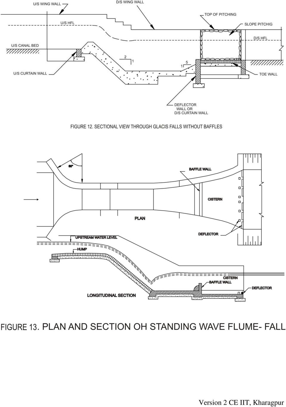
11 Falls with drop along inclined glacis These are falls with and inclined glacis along which the water glides down and the energy is dissipated by the action of a hydraulic jump at the toe of the structure. Inclined drops are often designed to function as flume measuring devices. These may be with and without baffles as shown in Figures 12 and 13 respectively and supplemented by friction blocks and other energy dissipating devices (Figure 14).

12
13 Similar type of fall was also developed in Punjab which was called the CDO type fall, as shown in Figure 15 (for hydraulic drop up to 1m) and Figure 16 (for hydraulic drop above 1m).
 and Figure 16 (for hydraulic drop above")
14

15 The glacis type falls may be modified in the following ways: (a) Flumed or un-flumed, depending upon the crest width being smaller or equal to the bed width of the canal (Figure17). (b) Meter or non-meter fall depending upon whether the canal fall may be used to measure the discharge as well. Details of a meter-fall is described in Lesson 3.10
 Meter or non-meter fall depending upon whether the canal fall may be used to")
16

17 The following appurtenant structures should be considered while providing a verticaldrop or a glacis-type fall: The floor of the falls should be able to resist the uplift pressure under the condition of dry canal and a high ground water table. Cut-off walls or curtain walls either of masonry or concrete should be provided at the upstream and downstream ends of the floors of the falls. Bed protection with dry brick pitching should be provided in the canal just upstream and downstream of the fall. Side protection should be provided at the upstream and downstream splays with brick pitching. Since falls are structures across a canal, it is usual for providing a bridge along with the fall structure for crossing the canal Canal regulators These include the cross regulator and the distributary head regulator structures for controlling the flow through a parent canal and its off-taking distributary as shown in Figure 1. They also help to maintain the water level in the canal on the upstream of the regulator. Canal regulators, which are gated structures, may be combined with bridges and falls for economic and other considerations, like topography, etc. A typical view of a distributary head regulator and a cross regulator (shown partly in section) is illustrated in Figure 18.

18 In the figure, the gates and gate hoisting arrangements have not been shown, for clarity. Further, the floor of the regulators would be protected on the upstream and downstream with concrete blocks and boulder apron. A typical sectional drawing through a regulator is shown in Figure 19.

19 The angle at which a distributary canal off-takes from the parent canal has to be decided carefully. The best angle is when the distributary takes off smoothly, as shown in Figure 20(a). Another alternative is to provide both channels (off-taking and parent) at an angle to the original direction of the parent canal (Figure 20b). When it becomes necessary for the parent canal to follow a straight alignment, the edge of the canal rather than the centre line should be considered in deciding the angle of off-take (Figure 20c). To prevent excessive entry of silt deposition at the mouth of the off-take, the entry angle should be kept to between 60 0 and For the hydraulic designs of cross regulators, one may refer to the Bureau of Indian Standard code IS: Criteria for hydraulic design of cross regulators for canals. The water entering in to the off-taking distributary canal from the parent canal may also draw suspended sediment load. The distributary should preferably be designed to draw sediment proportional to its flow, for maintaining non-siltation of either the parent canal or itself. For achieving this, three types of structures have been suggested as discussed below along with the relevant Bureau of Indian standard codes.

20 3.9.5 Silt vanes (Please refer to IS: Criteria for design of silt vanes for sediment control in off-taking canals for more details) Silt vanes, or King s vanes, are thin, vertical, curved parallel walled structures constructed of plain or reinforced concrete on the floor of the parent canal, just upstream of the off-taking canal. The height of the vanes may be about one-fourth to one-third of the depth of flow in the parent canal. The thickness of the vanes should be as small as possible and the spacing of the vanes may be kept about 1.5 times the vane height. To minimize silting tendency, the pitched floor on which the vanes are built should be about 0.15 m above the normal bed of the parent channel. A general three dimensional view of the vanes is shown in Figure 21 and a typical plan and sectional view in Figure 22.

21 3.9.6 Groyne walls or curved wings (Please refer to IS: Criteria for hydraulic design of groyne wall (curved wing) for sediment distribution at off-take points in a canal for more details) These are curved vertical walls, also called Gibb s groyne walls, which project out in to the parent canal from the downstream abutment of the off-taking canal. The groyne wall is provided in such a way that it divides the discharge of the parent canal in proportion of the discharge requirement of the off-taking canal with respect to the flow in the downstream parent canal. The groyne wall extends upstream in to the parent canal to cover ¾ to full width of the off-take. The proportional distribution of flow in to the offtaking canal is expected to divert proportional amount of sediment, too. A general view of a groyne wall is shown in Figure 23.
22 The distance of the nose from the upstream abutment of the off-take may be kept so as to direct adequate discharge in to the off-take. The height of the groyne wall should be at least 0.3m above the full supply level of the parent canal. At times, a combination of groyne wall and sediment vane may be provided Skimming platforms (Please refer to IS: Criteria for hydraulic design of skimming platform for sediment control in off-taking canal for more details). A skimming platform is an RCC slab resting on low height piers on the bed of the parent canal, and in front of the off-taking canal, and in front of the off-taking canal as shown in Figure 24.
23 This arrangement actually creates a kind of low tunnel at the bed of the parent canal, which allows the sediment moving along its bed to pass through downstream. The floor of the off-taking canal being above the level of the platform thus only takes suspended sediment load coming along with the main flow in the parent canal. A skimming platform arrangement is suitable where the parent channel is deep (about 2m or more) and the off-take is comparatively small. The tunnels should be at-least 0.6m deep. The upstream and downstream edges of the platform should be inclined at about 30 0 to the parent canal cross section. At times, silt vanes can be combined with a skimming platform. In that case, the piers of the platform are extended downstream in the form of vanes. A typical plan and section view of a skimming platform is shown in Figure 25.
24 3.9.8 Canal escapes These are structures meant to release excess water from a canal, which could be main canal, branch canal, distributary, minors etc. Though usually an irrigation system suffers from deficit supply in later years of its life, situations that might suddenly lead to accumulation of excess water in a certain reach of a canal network may occur due to the following reasons: Wrong operation of head works in trying to regulate flow in a long channel resulting in release of excess water than the total demand in the canal system downstream.
25 Excessive rainfall in the command area leading to reduced demand and consequent closure of downstream gates. Sudden closure of control gates due to a canal bank breach. The excess water in a canal results in the water level rising above the full supply level which, if allowed to overtop the canal banks, may cause erosion and subsequent breaches. Hence, canal escapes help in releasing the excess water from a canal at times of emergency. Moreover, when a canal is required to be emptied for repair works, the water may be let off through the escapes. Escapes as also built at the tail end of minors at the far ends of a canal network. These are required to maintain the required full supply level at the tail end of the canal branch. The construction feature of escapes allows it to be classified in to two types, as described below Weir or surface escapes These are constructed in the form of weirs, without any gate or shutter (Figure 26) and spills over when the water level of the canal goes above its crest level
26 Sluice or surplus escapes These are gated escapes with a very low crest height (Figure 27). Hence, these sluices can empty the canal much below its full supply level and at a very fast rate. In some cases, these escapes act as scouring sluices to facilitate removal of sediment. The locations for providing escapes are often determined on the availability of suitable drains, depressions or rivers with their bed level at or below the canal bed level so that any surplus water may be released quickly disposed through these natural outlets. Escapes may be necessary upstream of points where canals takeoff from a main canal branch. Escape upstream of major aqueducts is usually provided. Canal escapes may be provided at intervals of 15 to 20km for main canal and at 10 to 15km intervals for other canals. The capacity of an escape channel should be large enough to carry maximum escape discharge. These should be proper energy dissipation arrangements to later for all flow conditions. The structural and hydraulic design would be similar to that of regulators or sluices or weirs, as appropriate. The Bureau of Indian Standards code IS 6936:1992 (reaffirmed 1998) Guide for location, selection and hydraulic design of canal escapes may be referred to for further details.
27 References FAO Irrigation and Drainage paper 26/1: Small Hydraulic Structures, Volume 1 (1982) FAO Irrigation and Drainage paper 26/2: Small Hydraulic Structures, Volume 2 (1982) Garg, S K (1996) Irrigation engineering and hydraulic structures, Twelfth Edition, Khanna Publishers IS 4410 : Part 15 : Sec 4 : 1977 Glossary of terms relating to river valley projects: Part 15 Canal structures Section 4 Regulating works IS 6522 : 1972 Criteria for design of silt vanes for sediment control in offtaking canals IS 6531 : 1994 Canal Head Regulators - Criteria for Design IS 6936 : 1992 Guide for location, selection and hydraulic design of canal escapes IS 7114 : 1973 Criteria for hydraulic design of cross regulators for canals IS 7495 : 1974 Criteria for hydraulic design of silt selective head regulator for sediment control in offtaking canals IS 7880 : 1975 Criteria for hydraulic design of skimming platform for sediment control in offtaking canal IS: (reaffirmed 1998) Guide for location, selection and hydraulic design of canal escapes IS: Criteria for hydraulic design of cross regulators for canals Varshney, R S, Gupta, S C and Gupta, R L (1993) Theory and design of irrigation structures, Volume II, Sixth Edition, Nem Chand Publication
Lecture 24 Flumes & Channel Transitions. I. General Characteristics of Flumes. Flumes are often used:
 Lecture 24 Flumes & Channel Transitions I. General Characteristics of Flumes Flumes are often used: 1. Along contours of steep slopes where minimal excavation is desired 2. On flat terrain where it is
Experiment (13): Flow channel
: Flow channel") Introduction: An open channel is a duct in which the liquid flows with a free surface exposed to atmospheric pressure. Along the length of the duct, the pressure at the surface is therefore constant and
Introduction: An open channel is a duct in which the liquid flows with a free surface exposed to atmospheric pressure. Along the length of the duct, the pressure at the surface is therefore constant and
Emergency Spillways (Sediment basins)
") Emergency Spillways (Sediment basins) DRAINAGE CONTROL TECHNIQUE Low Gradient Velocity Control Short-Term Steep Gradient Channel Lining Medium-Long Term Outlet Control Soil Treatment Permanent [1] [1]
Emergency Spillways (Sediment basins) DRAINAGE CONTROL TECHNIQUE Low Gradient Velocity Control Short-Term Steep Gradient Channel Lining Medium-Long Term Outlet Control Soil Treatment Permanent [1] [1]
Exercise (4): Open Channel Flow - Gradually Varied Flow
: Open Channel Flow - Gradually Varied Flow") Exercise 4: Open Channel Flow - Gradually Varied Flow 1 A wide channel consists of three long reaches and has two gates located midway of the first and last reaches. The bed slopes for the three reaches
Exercise 4: Open Channel Flow - Gradually Varied Flow 1 A wide channel consists of three long reaches and has two gates located midway of the first and last reaches. The bed slopes for the three reaches
Lecture 6. Jump as energy dissipation Control of jump.
 Lecture 6 Jump as energy dissipation Control of jump. Jump as energy dissipation The high energy loss that occurs in a hydraulic jump has led to its adoption as a part of high energy dissipater system
EXAMPLES (OPEN-CHANNEL FLOW) AUTUMN 2015
 AUTUMN 2015") EXAMPLES (OPEN-CHANNEL FLOW) AUTUMN 2015 Normal and Critical Depths Q1. If the discharge in a channel of width 5 m is 20 m 3 s 1 and Manning s n is 0.02 m 1/3 s, find: (a) the normal depth and Froude number
EXAMPLES (OPEN-CHANNEL FLOW) AUTUMN 2015 Normal and Critical Depths Q1. If the discharge in a channel of width 5 m is 20 m 3 s 1 and Manning s n is 0.02 m 1/3 s, find: (a) the normal depth and Froude number
...Eq(11.6) The energy loss in the jump is dependent on the two depths y 1 and y 2 3 = E =...Eq(11.7)
 The energy loss in the jump is dependent on the two depths y 1 and y 2 3 = E =...Eq(11.7)") . Open Channel Flow Contd.5 Hydraulic Jump A hydraulic jump occurs when water in an open channel is flowing supercritical and is slowed by a deepening of the channel or obstruction in the channel. The
. Open Channel Flow Contd.5 Hydraulic Jump A hydraulic jump occurs when water in an open channel is flowing supercritical and is slowed by a deepening of the channel or obstruction in the channel. The
Open channel flow Basic principle
 Open channel flow Basic principle INTRODUCTION Flow in rivers, irrigation canals, drainage ditches and aqueducts are some examples for open channel flow. These flows occur with a free surface and the pressure
Outlet stabilization structure
 Overview of Sedimentation and Erosion Control Practices Practice no. 6.41 Outlet stabilization structure Erosion at the outlet of channels, culverts, and other structures is common, and can cause structural
2.0 BASIC CONCEPTS OF OPEN CHANNEL FLOW MEASUREMENT
 2.0 BASIC CONCEPTS OF OPEN CHANNEL FLOW MEASUREMENT Open channel flow is defined as flow in any channel where the liquid flows with a free surface. Open channel flow is not under pressure; gravity is the
How To Build A Road Into A Lake In The North Of The Korean Island Of Hongkoon
 3D view of intake - looking upstream from the west bank New intake access track forming upstream bund The intake is located at grid ref 204791,888654. The intake screen arrangement is a drop bar type screen
Open Channel Flow Measurement Weirs and Flumes
 Open Channel Flow Measurement Weirs and Flumes by Harlan H. Bengtson, PhD, P.E. 1. Introduction Your Course Title Here Measuring the flow rate of water in an open channel typically involves some type of
Sharp-Crested Weirs for Open Channel Flow Measurement, Course #506. Presented by:
 Sharp-Crested Weirs for Open Channel Flow Measurement, Course #506 Presented by: PDH Enterprises, LLC PO Box 942 Morrisville, NC 27560 www.pdhsite.com A weir is basically an obstruction in an open channel
BRIDGES ARE relatively expensive but often are
 Chapter 10 Bridges Chapter 10 Bridges Bridg Bridges -- usually the best, but most expensive drainage crossing structure. Protect bridges against scour. BRIDGES ARE relatively expensive but often are the
Module 7: Hydraulic Design of Sewers and Storm Water Drains. Lecture 7 : Hydraulic Design of Sewers and Storm Water Drains
 1 P age Module 7: Hydraulic Design of Sewers and Storm Water Drains Lecture 7 : Hydraulic Design of Sewers and Storm Water Drains 2 P age 7.1 General Consideration Generally, sewers are laid at steeper
Broad Crested Weirs. I. Introduction
 Lecture 9 Broad Crested Weirs I. Introduction The broad-crested weir is an open-channel flow measurement device which combines hydraulic characteristics of both weirs and flumes Sometimes the name ramp
Chapter 9. Steady Flow in Open channels
 Chapter 9 Steady Flow in Open channels Objectives Be able to define uniform open channel flow Solve uniform open channel flow using the Manning Equation 9.1 Uniform Flow in Open Channel Open-channel flows
Chapter 3 CULVERTS. Description. Importance to Maintenance & Water Quality. Culvert Profile
 Chapter 3 CULVERTS Description A culvert is a closed conduit used to convey water from one area to another, usually from one side of a road to the other side. Importance to Maintenance & Water Quality
HYDRAULICS. H91.8D/C - Computerized Open Surface Tilting Flow Channel - 10, 12.5, 15 and 20 m long
 HYDRAULICS H91.8D/C - Computerized Open Surface Tilting Flow Channel - 10, 12.5, 15 and 20 m long 1. General The series of channels H91.8D has been designed by Didacta Italia to study the hydrodynamic
CITY UTILITIES DESIGN STANDARDS MANUAL
 CITY UTILITIES DESIGN STANDARDS MANUAL Book 2 (SW) SW9 June 2015 SW9.01 Purpose This Chapter provides information for the design of open channels for the conveyance of stormwater in the City of Fort Wayne.
CEE 370 Fall 2015. Laboratory #3 Open Channel Flow
 CEE 70 Fall 015 Laboratory # Open Channel Flow Objective: The objective of this experiment is to measure the flow of fluid through open channels using a V-notch weir and a hydraulic jump. Introduction:
Welded Mesh Gabions and Mattresses River Protection Design Guide HY-TEN GABION SOLUTIONS Dunstall Hill Trading Estate, Gorsebrook Road,
 Welded Mesh Gabions and Mattresses River Protection Design Guide HY-TEN GABION SOLUTIONS Dunstall Hill Trading Estate, Gorsebrook Road, Wolverhampton, WV6 0PJ Tel 01902 712200 Fax 01902 714096 e-mail [email protected]
Index. protection. excavated drop inlet protection (Temporary) 6.50.1 6.51.1. Block and gravel inlet Protection (Temporary) 6.52.1
 6.50.1 6.51.1. Block and gravel inlet Protection (Temporary) 6.52.1") 6 Index inlet protection excavated drop inlet protection (Temporary) 6.50.1 HARDWARE CLOTH AND GRAVEL INLET PROTECTION Block and gravel inlet Protection (Temporary) sod drop inlet protection ROCK DOUGHNUT
6 Index inlet protection excavated drop inlet protection (Temporary) 6.50.1 HARDWARE CLOTH AND GRAVEL INLET PROTECTION Block and gravel inlet Protection (Temporary) sod drop inlet protection ROCK DOUGHNUT
Backwater Rise and Drag Characteristics of Bridge Piers under Subcritical
 European Water 36: 7-35, 11. 11 E.W. Publications Backwater Rise and Drag Characteristics of Bridge Piers under Subcritical Flow Conditions C.R. Suribabu *, R.M. Sabarish, R. Narasimhan and A.R. Chandhru
Chapter 13 OPEN-CHANNEL FLOW
 Fluid Mechanics: Fundamentals and Applications, 2nd Edition Yunus A. Cengel, John M. Cimbala McGraw-Hill, 2010 Lecture slides by Mehmet Kanoglu Copyright The McGraw-Hill Companies, Inc. Permission required
Open Channel Flow 2F-2. A. Introduction. B. Definitions. Design Manual Chapter 2 - Stormwater 2F - Open Channel Flow
 Design Manual Chapter 2 - Stormwater 2F - Open Channel Flow 2F-2 Open Channel Flow A. Introduction The beginning of any channel design or modification is to understand the hydraulics of the stream. The
Safe & Sound Bridge Terminology
 Safe & Sound Bridge Terminology Abutment A retaining wall supporting the ends of a bridge, and, in general, retaining or supporting the approach embankment. Approach The part of the bridge that carries
Moving Small Mountains Vesuvius Dam Rehab
 Moving Small Mountains Vesuvius Dam Rehab Susan L. Peterson, P.E., regional dams engineer, Eastern Region, Bedford, IN Note: The following article, Moving Small Mountains Vesuvius Dam Rehab, by Sue Peterson,
Sediment Entry Investigation at the 30 Degree Water Intake Installed at a Trapezoidal Channel
 World Applied Sciences Journal (): 82-88, 200 ISSN 88-4952 IDOSI Publications, 200 Sediment Entry Investigation at the 30 Degree Water Intake Installed at a Trapezoidal Channel 2 2 Mehdi Karami Moghadam,
Design Charts for Open-Channel Flow HDS 3 August 1961
 Design Charts for Open-Channel Flow HDS 3 August 1961 Welcome to HDS 3-Design Charts for Open-Channel Flow Table of Contents Preface DISCLAIMER: During the editing of this manual for conversion to an electronic
June 2007 CHAPTER 7 - CULVERTS 7.0 CHAPTER 7 - CULVERTS 7.1 GENERAL
 7.0 7.1 GENERAL For the purpose of this manual, culverts are defined as structures that are completely surrounded by soil and located below the surface of the roadway parallel to the general direction
RIPRAP From Massachusetts Erosion and Sediment Control Guidelines for Urban and Suburban Areas http://www.mass.gov/dep/water/laws/policies.
 RIPRAP From Massachusetts Erosion and Sediment Control Guidelines for Urban and Suburban Areas http://www.mass.gov/dep/water/laws/policies.htm#storm Definition: A permanent, erosion-resistant ground cover
STORM DRAINS CHAPTER 7
 CHAPTER 7 Chapter 7 - Storm Drains A storm drain is a drainage system that conveys water or stormwater, consisting of two or more pipes in a series connected by one or more structures. Storm drains collect
SECTION 08000 STORM DRAINAGE TABLE OF CONTENTS
 SECTION 08000 STORM DRAINAGE 08010 DESIGN A. Location B. Sizing TABLE OF CONTENTS 08020 MATERIALS A. Pipe Materials B. Structure Materials C. Installation D. Inlets and Outlets 08030 INSPECTIONS AND TESTING
Appendix 4-C. Open Channel Theory
 4-C-1 Appendix 4-C Open Channel Theory 4-C-2 Appendix 4.C - Table of Contents 4.C.1 Open Channel Flow Theory 4-C-3 4.C.2 Concepts 4-C-3 4.C.2.1 Specific Energy 4-C-3 4.C.2.2 Velocity Distribution Coefficient
A CASE-STUDY OF CUA_DAT CFRD IN VIETNAM
 A CASE-STUDY OF CUA_DAT CFRD IN VIETNAM Giang Pham Hong, Michel Hotakhanh, Nga Pham Hong, Hoai Nam Nguyen, Abstract:Dams have been taken an important role in time and surface redistribution of water for
1. Carry water under the canal 2. Carry water over the canal 3. Carry water into the canal
 Lecture 21 Culvert Design & Analysis Much of the following is based on the USBR publication: Design of Small Canal Structures (1978) I. Cross-Drainage Structures Cross-drainage is required when a canal
Hydraulics Prof. A. K. Sarma Department of Civil Engineering Indian Institute of Technology, Guwahati. Module No. # 02 Uniform Flow Lecture No.
 Hydraulics Prof. A. K. Sarma Department of Civil Engineering Indian Institute of Technology, Guwahati Module No. # 02 Uniform Flow Lecture No. # 04 Computation of Uniform Flow (Part 02) Welcome to this
Organization Chart for Design Organization
 CANAL DESIGN Organization Chart for Design Organization Chief Engineer (Design), SSNNL, Gandhinagar Superintending Engineer, Narmada Project Design Circle, Gandhinagar Unit-1 Unit-2 Unit-3 Unit-4 Unit-5
Module 9: Basics of Pumps and Hydraulics Instructor Guide
 Module 9: Basics of Pumps and Hydraulics Instructor Guide Activities for Unit 1 Basic Hydraulics Activity 1.1: Convert 45 psi to feet of head. 45 psis x 1 ft. = 103.8 ft 0.433 psi Activity 1.2: Determine
CHAPTER 9 CHANNELS APPENDIX A. Hydraulic Design Equations for Open Channel Flow
 CHAPTER 9 CHANNELS APPENDIX A Hydraulic Design Equations for Open Channel Flow SEPTEMBER 2009 CHAPTER 9 APPENDIX A Hydraulic Design Equations for Open Channel Flow Introduction The Equations presented
Riprap-lined Swale (RS)
") Riprap-lined Swale (RS) Practice Description A riprap-lined swale is a natural or constructed channel with an erosion-resistant rock lining designed to carry concentrated runoff to a stable outlet. This
Riprap-lined Swale (RS) Practice Description A riprap-lined swale is a natural or constructed channel with an erosion-resistant rock lining designed to carry concentrated runoff to a stable outlet. This
Open Channel Flow. M. Siavashi. School of Mechanical Engineering Iran University of Science and Technology
 M. Siavashi School of Mechanical Engineering Iran University of Science and Technology W ebpage: webpages.iust.ac.ir/msiavashi Email: [email protected] Landline: +98 21 77240391 Fall 2013 Introduction
Watershed Works Manual
 National Rural Employment Guarantee Act Watershed Works Manual DRAINAGE LINE TREATMENT: GABION STRUCTURE Baba Amte Centre for People s Empowerment Samaj Pragati Sahayog September 2006 Drainage Line Treatment:
DIVISION OF WATER QUALITY CONSTRUCTION GRANTS & LOANS SECTION FAST TRACK AUDIT CHECKLIST
 DIVISION OF WATER QUALITY CONSTRUCTION GRANTS & LOANS SECTION FAST TRACK AUDIT CHECKLIST CERTIFICATION 1. Did the engineer submit a certificate of completion utilizing the appropriate page of the issued
STANDARD AND SPECIFICATIONS FOR STORM DRAIN INLET PROTECTION
 STANDARD AND SPECIFICATIONS FOR STORM DRAIN INLET PROTECTION Design Criteria Drainage Area The drainage area for storm drain inlets shall not exceed one acre. The crest elevations of these practices shall
Topic 8: Open Channel Flow
 3.1 Course Number: CE 365K Course Title: Hydraulic Engineering Design Course Instructor: R.J. Charbeneau Subject: Open Channel Hydraulics Topics Covered: 8. Open Channel Flow and Manning Equation 9. Energy,
L_All_Vocatinal_Ed_Construction. Sector: Construction. Sr. No Specialisation Page No 1 Construction and Building Technology 02.
 L_All_Vocatinal_Ed_Construction Sector: Construction Sr. No Specialisation Page No 1 Construction and Building Technology 02 1 P a g e 2 P a g e VOCATIONAL EDUCATIONAL QUALIFICATION FRAMEWORK (Sector -
UNDER DRAINAGE AND FILTER DESIGN
 UNDER DRAINAGE AND FILTER DESIGN Tailings and HLP Workshop 28 April to 1 May 2010 INTRODUCTION The internal drainage is of crucial importance to the reliability and safety of a tailings dam throughout
Prattsville Berm Removal Project. 1.0 Project Location
 Prattsville Berm Removal Project 1.0 Project Location The project site is located between the New York State Route 23 Bridge over the Schoharie Creek and the Schoharie Reservoir. The restoration plan encompassed
SECTION 5 - STORM DRAINS
 Drainage Criteria Manual SECTION 5 - STORM DRAINS 5.1.0 GENERAL This The purpose of this section discusses briefly is to consider the hydraulic aspects of storm drains and their appurtenances in a storm
WATER STORAGE, TRANSPORT, AND DISTRIBUTION Multi-Dam Systems and their Operation - J.J. Cassidy MULTI-DAM SYSTEMS AND THEIR OPERATION
 MULTI-DAM SYSTEMS AND THEIR OPERATION J.J. Cassidy Consulting Hydraulic and Hydrologic Engineer, Concord, California, USA Keywords: Dams, reservoirs, rivers, water storage, dam safety, floods, environment,
Module 7 (Lecture 24 to 28) RETAINING WALLS
 RETAINING WALLS") Module 7 (Lecture 24 to 28) RETAINING WALLS Topics 24.1 INTRODUCTION 24.2 GRAVITY AND CANTILEVER WALLS 24.3 PROPORTIONING RETAINING WALLS 24.4 APPLICATION OF LATERAL EARTH PRESSURE THEORIES TO DESIGN 24.5
Module 7 (Lecture 24 to 28) RETAINING WALLS Topics 24.1 INTRODUCTION 24.2 GRAVITY AND CANTILEVER WALLS 24.3 PROPORTIONING RETAINING WALLS 24.4 APPLICATION OF LATERAL EARTH PRESSURE THEORIES TO DESIGN 24.5
ICOLD POSITION PAPER ON DAM SAFETY AND EARTHQUAKES
 ICOLD POSITION PAPER ON DAM SAFETY AND EARTHQUAKES August 2012 Dam Safety and Earthquakes Position Paper of International Commission on Large Dams (ICOLD) Prepared by ICOLD Committee on Seismic Aspects
REINFORCED CONCRETE. Reinforced Concrete Design. A Fundamental Approach - Fifth Edition. Walls are generally used to provide lateral support for:
 HANDOUT REINFORCED CONCRETE Reinforced Concrete Design A Fundamental Approach - Fifth Edition RETAINING WALLS Fifth Edition A. J. Clark School of Engineering Department of Civil and Environmental Engineering
CITY OF VAUGHAN SCHEDULE O LOT GRADING DESIGN FOR RESIDENTIAL DEVELOPMENT
 Page 1 CITY OF VAUGHAN SCHEDULE O LOT GRADING DESIGN FOR RESIDENTIAL DEVELOPMENT CIVIC CENTRE 2141 MAJOR MACKENZIE DRIVE MAPLE ONTARIO L6A 1T1 905-832-2281 Page 2 SECTION 1 - GENERAL OBJECTIVES To provide
APPLICATION OF GIS AND REMOTE SENSING IN IRRIGATION NETWORKS MANAGEMENT
 Tenth International Water Technology Conference, IWTC10 2006, Alexandria, Egypt 21 APPLICATION OF GIS AND REMOTE SENSING IN IRRIGATION NETWORKS MANAGEMENT Sherif M. El-Sayed Researcher, Hydraulics Research
BANGKOK FLOOD PROTECTION SYSTEM Bangkok Metropolitan Administration (BMA)
") BANGKOK FLOOD PROTECTION SYSTEM Bangkok Metropolitan Administration (BMA) Catchment area of Chao Phraya River is 160,000 sq.km. or about 1/3 of the country The Chao Phraya River flows passing through Bangkok
BANGKOK FLOOD PROTECTION SYSTEM Bangkok Metropolitan Administration (BMA) Catchment area of Chao Phraya River is 160,000 sq.km. or about 1/3 of the country The Chao Phraya River flows passing through Bangkok
Section 402. STORM SEWERS
 402.02 Section 402. STORM SEWERS 402.01. Description. This work consists of constructing storm sewers of the size and class required, including excavation, bedding, and backfill. 402.02. Materials. Provide
STRUCTURES. 1.1. Excavation and backfill for structures should conform to the topic EXCAVATION AND BACKFILL.
 STRUCTURES 1. General. Critical structures may impact the integrity of a flood control project in several manners such as the excavation for construction of the structure, the type of foundation, backfill
How To Check For Scour At A Bridge
 Case Studies Bridge Scour Inspection and Repair Edward P. Foltyn, P.E. Senior Hydraulic Engineer ODOT Bridge Unit 2013 PNW Bridge Inspectors Conference April 2013 REFERENCES Stream Stability at Highway
Property Care White Papers. Site Drainage: Monitor and Maintain
 Monitor and Maintain Site Drainage Good site drainage is an important part of keeping water issues from affecting the building. The upkeep of existing systems should be an important part of any maintenance
Numerical Investigation of Angle and Geometric of L-Shape Groin on the Flow and Erosion Regime at River Bends
 World Applied Sciences Journal 15 (2): 279-284, 2011 ISSN 1818-4952 IDOSI Publications, 2011 Numerical Investigation of Angle and Geometric of L-Shape Groin on the Flow and Erosion Regime at River Bends
SECTION 108 - INLETS 108.1 INLET LOCATIONS
 Greene County Design Standards -Adopted April 5, 1999 SECTION 108 - INLETS SECTION 108 - INLETS 108.1 INLET LOCATIONS 108.2 INLET INTERCEPTION CAPACITIES 108.2.1 Clogging Factors 108.3 INTERCEPTION AND
Final. Contact person: Colin Whittemore Aurecon Centre 1 Century City Drive Waterford Precinct, Century City Cape Town, South Africa
 Review Report and Recommendations for the Remediation of Flood Damage at the Berg River Causeway and the Dam Bypass Channel on Portion of Farms 1646 and 1014, Franschhoek Contact person: Colin Whittemore
APPENDIX C INLETS. The application and types of storm drainage inlets are presented in detail in this Appendix.
 Storm Drainage 13-C-1 APPENDIX C INLETS 1.0 Introduction The application and types of storm drainage inlets are presented in detail in this Appendix. 2.0 Inlet Locations Inlets are required at locations
Gertrudys B. Adkins, Ph.D. Division of Water Rights 2006
 FLOW MEASUREMENT DEVICES By Gertrudys B. Adkins, Ph.D. Division of Water Rights 2006 TABLE OF CONTENT INTRODUCTION...1 FLOW MEASUREMENT DEVICES...1 FLOW MEASUREMENT BASICS...2 OPEN CHANNEL FLOW METHODS...3
CHAPTER 2 HYDRAULICS OF SEWERS
 CHAPTER 2 HYDRAULICS OF SEWERS SANITARY SEWERS The hydraulic design procedure for sewers requires: 1. Determination of Sewer System Type 2. Determination of Design Flow 3. Selection of Pipe Size 4. Determination
FLOW CONDITIONER DESIGN FOR IMPROVING OPEN CHANNEL FLOW MEASUREMENT ACCURACY FROM A SONTEK ARGONAUT-SW
 FLOW CONDITIONER DESIGN FOR IMPROVING OPEN CHANNEL FLOW MEASUREMENT ACCURACY FROM A SONTEK ARGONAUT-SW Daniel J. Howes, P.E. 1 Charles M. Burt, Ph.D., P.E. 2 Brett F. Sanders, Ph.D. 3 ABSTRACT Acoustic
Open Channel Flow in Aquaculture
 SRAC Publication No. 74 Southern Regional Aquaculture Center March 1995 PR VI Open Channel Flow in Aquaculture J. David Bankston, Jr. 1 and Fred Eugene Baker Open channel flow of water has been used in
SERVICE LINE EXTENSION AND SERVICE LINE CONNECTION CONDENSED SANITARY SEWER SYSTEM INSTALLATION SPECIFICATIONS
 1001 SOUTH LEECHBURG HILL LEECHBURG, PA 15656 Phone: 724-845-9355 Fax: 724-845-1186 SERVICE LINE EXTENSION AND SERVICE LINE CONNECTION CONDENSED SANITARY SEWER SYSTEM INSTALLATION SPECIFICATIONS 1. General
Small Dam Hazard Assessment Inventory
 Small Dam Hazard Assessment Inventory What would happen if your dam were to fail? This is a question that most dam owners hope they will never have to answer. However it is a question you, as a responsible
Section 3. HYDRAULIC DESIGN A. Weirs and Orifices
 Section 3. HYDRAULIC DESIGN A. Weirs and Orifices NOTE: Some of the graphs contained in this section are copied from the Los Angeles Hydraulics Manual and we wish to give them credit for their efforts.
Storm Drain Inlet Protection - IP
 Storm Drain Inlet Protection - IP DEFINITION A temporary protective device formed around a storm drain drop inlet to trap sediment. PURPOSE To prevent sediment from entering storm drainage systems, prior
OPEN-CHANNEL FLOW. Free surface. P atm
 OPEN-CHANNEL FLOW Open-channel flow is a flow of liquid (basically water) in a conduit with a free surface. That is a surface on which pressure is equal to local atmospheric pressure. P atm Free surface
Storm Drainage Systems 11.9-1
 Storm Drainage Systems 11.9-1 11.9 Gutter Flow Calculations 11.9.1 Introduction Gutter flow calculations are necessary in order to relate the quantity of flow (Q) in the curbed channel to the spread of
Lecture 22 Example Culvert Design Much of the following is based on the USBR technical publication Design of Small Canal Structures (1978)
") Lecture 22 Example Culvert Design Much of the following is based on the USBR technical publication Design of Small Canal Structures (1978) I. An Example Culvert Design Design a concrete culvert using the
Lecture 22 Example Culvert Design Much of the following is based on the USBR technical publication Design of Small Canal Structures (1978) I. An Example Culvert Design Design a concrete culvert using the
NUMERICAL ANALYSIS OF SEEPAGE THROUGH EMBANKMENT DAMS (CASE STUDY: KOCHARY DAM, GOLPAYEGAN)
") NUMERICAL ANALYSIS OF SEEPAGE THROUGH EMBANKMENT DAMS (CASE STUDY: KOCHARY DAM, GOLPAYEGAN) *Reza Naghmehkhan Dahande 1 and Ahmad Taheri 2 1 Department of Civil Engineering-Water Management, Islamic Azad
NUMERICAL ANALYSIS OF SEEPAGE THROUGH EMBANKMENT DAMS (CASE STUDY: KOCHARY DAM, GOLPAYEGAN) *Reza Naghmehkhan Dahande 1 and Ahmad Taheri 2 1 Department of Civil Engineering-Water Management, Islamic Azad
State of Illinois Department Of Transportation CONSTRUCTION INSPECTOR S CHECKLIST FOR STORM SEWERS
 State of Illinois Department Of Transportation CONSTRUCTION INSPECTOR S CHECKLIST FOR STORM SEWERS While its use is not required, this checklist has been prepared to provide the field inspector a summary
8.1.3 General Design Guidelines. The following guidelines shall be used when designing inlets along a street section:
 . Introduction Presented in this chapter are the criteria and methodology for design and evaluation of storm sewer inlets located in Town of Castle Rock. The review of all planning submittals will be based
USSD Workshop on Dam Break Analysis Applied to Tailings Dams
 USSD Workshop on Dam Break Analysis Applied to Tailings Dams Antecedents Newtonian / non-newtonian flows Available models that allow the simulation of non- Newtonian flows (tailings) Other models used
What is the most obvious difference between pipe flow and open channel flow????????????? (in terms of flow conditions and energy situation)
") OPEN CHANNEL FLOW 1 3 Question What is the most obvious difference between pipe flow and open channel flow????????????? (in terms of flow conditions and energy situation) Typical open channel shapes Figure
OPEN CHANNEL FLOW 1 3 Question What is the most obvious difference between pipe flow and open channel flow????????????? (in terms of flow conditions and energy situation) Typical open channel shapes Figure
CHAPTER 3 STORM DRAINAGE SYSTEMS
 CHAPTER 3 STORM DRAINAGE SYSTEMS 3.7 Storm Drains 3.7.1 Introduction After the tentative locations of inlets, drain pipes, and outfalls with tail-waters have been determined and the inlets sized, the next
CHAPTER 11 STORM DRAINAGE
 CHAPTER STORM DRAINAGE SECTION PC 0 GENERAL 0. Scope. The provisions of this chapter shall govern the materials, design, construction and installation of storm drainage. Storm water discharge shall be
Flow Measurement Calibration and Measurement
 Calibration and Measurement Flow Measurement Flow measurement for agricultural irrigation delivery can be accomplished with four general approaches. These categories are generalized below. I. Standard
AS COMPETITION PAPER 2008
 AS COMPETITION PAPER 28 Name School Town & County Total Mark/5 Time Allowed: One hour Attempt as many questions as you can. Write your answers on this question paper. Marks allocated for each question
Chapter 10. Open- Channel Flow
 Updated: Sept 3 2013 Created by Dr. İsmail HALTAŞ Created: Sept 3 2013 Chapter 10 Open- Channel Flow based on Fundamentals of Fluid Mechanics 6th EdiAon By Munson 2009* *some of the Figures and Tables
CHAPTER 860 OPEN CHANNELS
 HIGHWAY DESIGN MANUAL 860-1 CHAPTER 860 OPEN CHANNELS Topic 861 - General Index 861.1 - Introduction An open channel is a conveyance in which water flows with a free surface. Although closed conduits such
CHAPTER 3A Environmental Guidelines for STREAM CROSSING BY ALL-TERRAIN VEHICLES
 GOVERNMENT OF NEWFOUNDLAND AND LABRADOR DEPARTMENT OF ENVIRONMENT AND LABOUR CHAPTER 3A Environmental Guidelines for STREAM CROSSING BY ALL-TERRAIN VEHICLES WATER RESOURCES MANAGEMENT DIVISION Water Investigations
Seattle Public Utilities. Natural Drainage Systems (NDS) Maintenance Manual
 Maintenance Manual") Seattle Public Utilities Natural Drainage Systems (NDS) Maintenance Manual 1 Revision Date: December 2007 2 Table of Contents I. Overview... 4 II. How to Use This Manual... 4 III. NDS Contacts... 4 List
Seattle Public Utilities Natural Drainage Systems (NDS) Maintenance Manual 1 Revision Date: December 2007 2 Table of Contents I. Overview... 4 II. How to Use This Manual... 4 III. NDS Contacts... 4 List
For the purposes of this article the Shannon can conveniently be divided into five sections:
 Volume 29 Number 3 Autumn Inland Waterways News Table of Contents Shannon Water Level Management Robert Cullen The water levels along the Shannon River and its lakes are the subject of much discussion,
3.4 DRAINAGE PLAN. 3.4.1 Characteristics of Existing Drainages. 3.4.2 Master Drainage System. Section 3: Development Plan BUTTERFIELD SPECIFIC PLAN
 3.4 DRAINAGE PLAN This section describes the existing onsite drainage characteristics and improvements proposed within this Specific Plan. Following this description, drainage plan development standards
APPENDIX F. Baker County. Mason Dam Hydroelectric Project FERC No. P-12686. Turbidity Monitoring Plan
 APPENDIX F Baker County Mason Dam Hydroelectric Project FERC No. P-12686 Turbidity Monitoring Plan April 2011 857 Table of Contents 1.0 Introduction 1 2.0 Purpose and Scope 2 3.0 Turbidity Monitoring and
The Alternatives of Flood Mitigation in The Downstream Area of Mun River Basin
 The Alternatives of Flood Mitigation in The Downstream Area of Mun River Basin Dr.Phattaporn Mekpruksawong 1, Thana Suwattana 2 and Narong Meepayoong 3 1 Senior Civil Engineer, Office of Project Management,
CHAPTER 4 OPEN CHANNEL HYDRAULICS
 CHAPTER 4 OPEN CHANNEL HYDRAULICS 4. Introduction Open channel flow refers to any flow that occupies a defined channel and has a free surface. Uniform flow has been defined as flow with straight parallel
Stormwater/Wetland Pond Construction Inspection Checklist
 : Construction Inspection ChecklistsTools Stormwater/Wetland Pond Construction Inspection Checklist Project: Location: Site Status: Date: Time: Inspector: SATISFACTORY/ UNSATISFACTORY COMMENTS Pre-Construction/Materials
DRAINAGE CRITERIA MANUAL (V. 2) CULVERTS CONTENTS
 CULVERTS CONTENTS") DRAINAGE CRITERIA MANUAL (V. 2) CONTENTS Section Page CU 1.0 INTRODUCTION AND OVERVIEW... 1 1.1 Required Design Information... 3 1.1.1 Discharge... 4 1.1.2 Headwater... 4 1.1.3 Tailwater... 5 1.1.4 Outlet
DRAINAGE CRITERIA MANUAL (V. 2) CONTENTS Section Page CU 1.0 INTRODUCTION AND OVERVIEW... 1 1.1 Required Design Information... 3 1.1.1 Discharge... 4 1.1.2 Headwater... 4 1.1.3 Tailwater... 5 1.1.4 Outlet
Chapter 2. Derivation of the Equations of Open Channel Flow. 2.1 General Considerations
 Chapter 2. Derivation of the Equations of Open Channel Flow 2.1 General Considerations Of interest is water flowing in a channel with a free surface, which is usually referred to as open channel flow.
ESTIMATING DISCHARGE AND STREAM FLOWS
 ESTIMATING DISCHARGE AND STREAM FLOWS A Guide for Sand and Gravel Operators Prepared by: Joy P. Michaud and Marlies Wierenga, EnviroVision Art and design by: S. Noel, Noel Design, LLC July 2005 Ecology