: Service Information: Fuel Tank System
|
|
|
- Antonia Gallagher
- 9 years ago
- Views:
Transcription
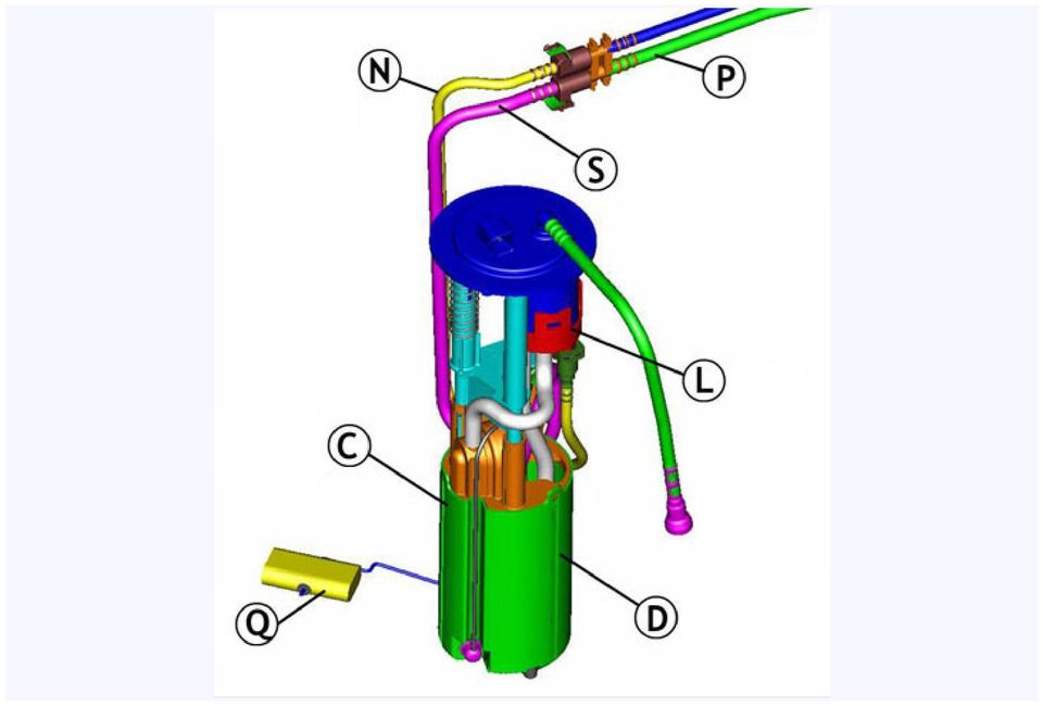
1 : Service Information: Fuel Tank System Corvette and Cadillac XLR Partway through model year 2003, a new fuel tank system was introduced on the Corvette (fig. 1). This system continues with slight differences in the 2004 Corvette and Cadillac XLR. TIP: For 2003 Corvettes only, this system was designated by RPO code FFS. However, this name has been unofficially applied to all vehicles with the new system. Advantages and Features The new fuel tank system was designed to accommodate future LEV 2 emission requirements. This was accomplished by moving as many components and fuel lines as possible inside the fuel tanks, to minimize hydrocarbon emissions. A flexible metal crossover hose assembly replaces the former rubber one, because the permeable rubber allowed a small amount of hydrocarbon to pass through. The redesign also includes more isolation and noise control for the electric fuel pump, which now has greater flow capacity to supply higher output engines. Component Layout TIP: Use the reference letters to identify and locate the various components. A Left side tank B Right side tank C Fuel sensor reservoir D Turbine fuel pump E Venturi pump F Fuel fill hose G Secondary fuel pressure regulator H Siphon jet pump J FLVV K Crossover hose L Filter M Fuel feed pipe to engine N Fuel feed pipe to RH tank P Fuel return pipe to LH tank Q Left fuel level sensor R Right fuel level sensor S Anti-siphon hole T Fuel pump speed control module U EVAP canister V Primary fuel pressure regulator W Check valve

2 TIP: On the XLR only, a speed control module (T) slows the fuel pump when the engine is idling, to further control pump noise. Two fuel tanks are used, and they re joined by crossover plumbing (fig. 2 and fig. 3). The left side (driver side) tank (A) is considered the primary, and the right side (passenger side) is secondary (B). Each tank contains a sensor module, which includes a float and resistor card. On the left side, the sender module includes a reservoir (C), containing the turbine fuel pump (D). There s also a primary fuel pressure regulator (V) and a venturi pump (E). The left tank is also supplied by the fuel fill hose (F), and has a rollover vent valve. On the right side, the sender module contains a secondary fuel pressure regulator (G) and a siphon jet pump (H). There is also a fill limiting vent valve (FLVV) (J). Operation When the fuel tanks are filled, fuel first fills the left tank. As the fuel rises to the level of the crossover (K), fuel flows into the right tank. As fuel occupies the interconnected tanks, air is forced to vent from the tanks, through the FLVV in the right tank. When both tanks are full, the FLVV float in the right tank closes, preventing fuel from entering the vent system. This also causes fuel to back up in the fill hose, causing the gas pump nozzle to shut off. When the engine is running (fig. 4), the turbine fuel pump (D) in the left tank pressurizes the fuel feed pipe (M). The entire fuel supply system, from the pump to the injectors, is pressurized. The turbine pump creates more pressure and more fuel flow than the engine needs. Excess pressure and excess fuel is allowed to bleed back into the left tank by the primary fuel pressure regulator (V) within the tank.
 and a venturi pump (E). The left tank is also supplied by the fuel fill hose (F), and has a rollover vent valve.")
3 TIP: The pressure regulator is in the fuel tank, not on the fuel rail on the engine. This type of fuel system is called returnless, or demand. This means that excess fuel is diverted before it leaves the tank, instead of passing through the fuel rail before being diverted. The result is that hot fuel is not constantly returning from the engine compartment, so the fuel in the tank stays cooler, improving evaporative emissions. The majority of the pressurized fuel is directed through the filter (L) and on to the fuel feed pipe (M) to the engine, where it is injected into the cylinders for combustion. Some of the pressurized fuel is directed through a feed pipe (N) inside the crossover hose, to a siphon jet pump in the right tank. The jet pump relies on the venturi effect to use pressurized fuel to draw additional fuel from the tank. The combined fuel then flows from the right tank to the left tank, through a return pipe (P) inside the crossover hose. The jet pump is able to move enough fuel to ensure that all of the fuel in the right tank is consumed before the level in the left tank begins to drop. TIP: The return tube in the left tank has an anti-siphon hole (S), so the fuel in the left tank does not siphon back to the right side when the vehicle is shut down. Some of the pressurized fuel is directed to a venturi pump in the left tank. This pump uses fuel flow to siphon fuel from the main tank into the reservoir, to keep the turbine pump supplied with fuel at all times. As the left tank fuel level drops, the venturi pump scavenges all of the remaining fuel into the reservoir, regardless of the vehicle s attitude. When the engine is shut off and the turbine pump stops, a reverse flow check valve (W) maintains pressure in the system to ensure rapid pressure buildup during the next startup cycle. Operation of Fuel Level Gauge When the fuel system is operating as designed, starting with both tanks full, the left tank will remain full until the right tank is depleted. Then the left tank will be emptied. Each fuel tank has its own sensor (Q and R in the illustrations). Modules are shown in figure 5 (LH module) and figure 6 (RH module). The PCM supplies a reference of 5 volts to the two sensors. Each sensor operates across a range from full (2.5 volts) to empty (0.7 volts). The PCM monitors the fuel level sensor voltages and calculates how much fuel is in the two tanks. The readout of the IP fuel level gauge is a result of this calculation.
 and on to the fuel feed pipe (M) to the engine, where it is injected into the cylinders for combustion.")
4
5 TIP: The fuel level sensors can be monitored with a Tech 2. Several zones are used to describe various combinations of fuel levels in the two tanks. Zone 1 -- The LH voltage is above its full threshold (typically calibrated to 2.4 volts) and the RH voltage is above its empty threshold (typically calibrated to 0.8 volts). Fuel volume = capacity of LH tank + volume in RH tank. This is the normal condition, before the fuel in the RH tank is completely consumed. Zone 2 -- The LH voltage is above full threshold and RH is below empty threshold. This is also known as the deadband zone. Fuel volume = volume in LH tank + deadband volume - fuel used since entering zone. This is also a normal condition. It occurs because the actual amount of fuel in the tanks cannot be precisely indicated by the positions of the floats. That is, when the float reaches the top of its travel, it s possible that the tank will hold additional fuel, which does not cause the float to move higher. Similarly, when the float reaches the bottom of its range, there may still be some fuel in the tank, and the float does not move any lower as the remaining fuel is consumed. So, the fuel in the bottom of the RH tank and the top of the LH tank will be consumed without either float moving. This is the deadband. Zone 4 -- The LH voltage is below full threshold value. Fuel volume = volume in LH tank. This condition occurs just after the zone 2 deadband is passed. All of the fuel is gone from the RH tank, and the LH sensor has begun to move down. The amount of fuel in the LH tank is all that remains. Zone 5 -- The LH voltage is below its full threshold and the RH voltage is above its empty threshold. Fuel volume = volume in LH tank = volume in RH tank. This is a condition that should not occur in normal operation, because the RH tank should be consumed before the float in the LH tank begins to drop. If the fuel system is in zone 5 for a certain amount of time, a DTC (1431, 2066 or 2636) will set, and the fuel volume will be reported as zero by the fuel gauge.

6 A zone 5 condition could occur if the jet pump in the RH tank becomes clogged, preventing fuel from being siphoned from the RH tank. In this case, only fuel in the LH tank is available. TIP: Service kits are available for each sensor, including: - float - wire arm - wiper - card - card holder Diagnostic Situations The following situations may apply to the Corvette (C5), the Cadillac (XLR) or both, as noted. Jet Pump Clog (C5, XLR) -- If the jet pump in the RH tank becomes clogged, fuel will not transfer to the LH tank. When this occurs, the vehicle eventually runs out of fuel, even though there is actually some in the RH tank. When the DTC (1431, 2066 or 2636) sets, the fuel gauge drops to empty and the customer perceives an erratic gauge. One cause of this condition was a piece of plastic left in the jet pump during the manufacturing process. This has been remedied. Fill Quality (C5) -- A customer may comment that the fuel nozzle shuts off prematurely, before the fuel tanks are full. The maximum flow rate for gas station pumps is supposed to be 10 gallons (37.9 L) per minute, and the fuel system is designed to accommodate this rate. TIP: In reality, pump nozzles vary considerably in configuration, flow and shutoff sensitivity. Ask the customer if the condition occurs at all stations, all the time, or at just one pump. This could point to a pump nozzle problem, not a vehicle problem. Be sure the rubber hose to the canister vent solenoid (next to the transmission) is not restricted and that the vent solenoid is not stuck closed. Both can cause fuel to back up in the tanks and filler hose, causing the pump nozzle to shut off. TIP: A replacement filler hose between the fill pipe and the LH fuel tank is available with a smaller inside diameter for C5. Although this sounds like it would make the condition worse, the smaller diameter allows less swirling, creating smoother fuel flow. A bulletin is pending. Regulator Not Seated, Clip Loose (C5, XLR) -- If the clip retaining either regulator is not fully engaged, the fuel system will lose pressure and the vehicle may stall. This condition was remedied in production. If the secondary regulator (right tank) is not seated, it could result in fuel not transferring from the right tank. It could also cause long crank times, because residual pressure is lost in the fuel feed pipe to the engine when the engine is shut down. TIP: With the engine off, a pressure gauge connected at the fuel rail should indicate 52 psi (359 kpa). If pressure drops rapidly, the regulator may be unseated. Open Fuel Level Sensor Circuit (C5, XLR) -- If an open occurs in a fuel level sensor circuit, the fuel gauge will drop to empty and a DTC will set. This could be caused by an unseated electrical terminal. Check the wiring circuits before replacing fuel system components. Another cause, which has been corrected, was the sensor wiper fingers not in contact with the resistor card, over the full sweep of the sensor. TIP: The DTC specifies which sensor circuit has the issue. Only that sensor should be replaced. LH Module Opening Too Small (C5, XLR) -- In some LH tanks, the module opening was undersized, making it difficult or impossible to remove the module. This has been corrected in production. TIP: In any case, be careful of the sensor float wire when removing the module, to avoid damage. Service Procedure Notes TIP: Refer to IDL course D, Technology Close-Up from October 2002, for additional information. TIP: Always consult SI before performing a service procedure. The following are highlights and tips only. Removing Fuel Tanks -- The crossover hose must be disconnected from a fuel tank which is being removed. The

7 crossover is located above the driveline and exhaust system, making removal appear difficult. Both SI and the Labor Time Guide allow lowering the driveline and exhaust for access. See Driveline Support Assembly Replacement in SI. Once you have performed this procedure, you will gain enough knowledge of the components that you may be able to do the procedure in the future without lowering the driveline. Crossover Hose -- The crossover hose is made of corrugated flexible stainless steel. It is retained to each fuel tank by a collar and a CPA (Connector Position Assurance). With the CPA aside, the collar can be turned by hand. It may be necessary to wiggle the crossover while pulling it straight out -- DO NOT TWIST. The fuel feed and fuel return pipes for the transfer pump are inside the crossover, and are sealed with O-rings. The crossover is sealed to each tank with two O-rings. When installing the crossover, lube the O-rings and O-ring sealing surfaces with rubber lubricant. Then align the pipes and push the crossover into place. DO NOT FORCE. TIP: There is a T-shaped alignment feature (fig. 7) between the feed pipes which can be assembled only one way. With the crossover in place, turn the collar. If the crossover and pipes are properly aligned and assembled, the collar can be turned with two fingers. Then snap the CPA into place. Fuel Tank Module Replacement -- It is necessary to remove the fuel tank from the vehicle before removing the module. Procedures are different for LH and RH tanks. TIP: Fuel Sensor Lock Ring Tool J-39765A is required. When the lock ring is loosened, the module will spring upward, because it is spring-loaded to ensure it is bottomreferenced and to resist noise. Follow the SI procedure exactly. It is necessary to disconnect and reconnect numerous fuel lines. The only access is through the module and crossover openings. TIP: When the module is installed, be sure to check the empty and full readings of the fuel level sensor. Your DMM should read 40 ohms with the tank in vehicle orientation (simulating empty) and 250 ohms with the tank upside down (simulating full). Fuel Line Quick Connectors Fuel lines use quick connectors, described in the February 2004 TechLink. See page 6 for details. TIP: To release, push on the retainer using hand pressure only. Do not attempt to remove it. If the retainer becomes broken, it can be replaced (fig. 8) using the following part number.
.")
8 5/16-inch (0.3125) 3/8- inch (0.375) 5/8-inch (0.625) External vapor and internal liquid lines Internal liquid lines FLVV connector to the evap canister Bulletin A -- This bulletin applies only to vehicles with the previous fuel system, which could be affected by fuel with an aggressive sulfur content. It does not apply to any XLR or Corvette with the FFS fuel system. DO NOT use this bulletin to justify reprogramming the PCM or replacing fuel sensors/modules in vehicles with the FFS fuel system. TIP: In the new system, DO NOT reprogram the PCM unless specifically told to do so by a diagnostic procedure. - Thanks to Dave Libby, Terry Stone and Dave Peacy, GM TechLink, March 2004 General Motors bulletins are intended for use by professional technicians, not a "do-it-yourselfer". They are written to inform those technicians of conditions that may occur on some vehicles, or to provide information that could assist in the proper service of a vehicle. Properly trained technicians have the equipment, tools, safety instructions and know-how to do a job properly and safely. If a condition is described, do not assume that the bulletin applies to your vehicle, or that your vehicle will have that condition. See a General Motors dealer servicing your brand of General Motors vehicle for information on whether your vehicle may benefit from the information. Copyright General Motors Corporation. All Rights Reserved.

The On-Board Refueling Vapor Recovery (ORVR) Evaporative Emission (EVAP) system.
 Evaporative Emission (EVAP) system.") «1A: Description and Operation» Overview The Evaporative Emission (EVAP) system prevents fuel vapor build-up in the sealed fuel tank. Fuel vapors trapped in the sealed tank are vented through the vapor
«1A: Description and Operation» Overview The Evaporative Emission (EVAP) system prevents fuel vapor build-up in the sealed fuel tank. Fuel vapors trapped in the sealed tank are vented through the vapor
E - THEORY/OPERATION
 E - THEORY/OPERATION 1995 Volvo 850 1995 ENGINE PERFORMANCE Volvo - Theory & Operation 850 INTRODUCTION This article covers basic description and operation of engine performance-related systems and components.
X-TYPE. Fuel System Drivability/Starting Issues Customer Complaints Diagnostic Procedures
 SERVICE DATE 09/02 Amended 12/03 X-TYPE TECHNICAL BULLETIN Fuel System Drivability/Starting Issues Customer Complaints Diagnostic Procedures MODEL VIN Remove and destroy Bulletin XT310-02, dated 09/02.
Evaporative emissions system
 just a test. Evaporative emissions system 20-48 Function description of EVAP canister system Depending upon the air pressure and ambient temperature, fuel vapor will form above the level of fuel in the
Oregon Fuel Injection
 FORD POWERSTROKE DIAGNOSTICS 1994-2003 This guide is not a substitute for the proper diagnostic manuals and a scan tool. It is intended to be used with the proper tools to help diagnose and solve drivability
DANGER DANGER. General Information. Safety Is Your Responsibility. Ordering Parts. Contact Information
 Safety Safety Is Your Responsibility DANGER To avoid personal injury or death, carefully read and understand all instructions pertaining to the Anthony Liftgates product. Do not attempt to install, operate,
Unit 24: Applications of Pneumatics and Hydraulics
 Unit 24: Applications of Pneumatics and Hydraulics Unit code: J/601/1496 QCF level: 4 Credit value: 15 OUTCOME 2 TUTORIAL 4 DIRECTIONAL CONTROL VALVES The material needed for outcome 2 is very extensive
ENGINE FUEL FUEL FILTER... FUEL HEATER... INJECTOR... SUPPLY PUMP... COMMON RAIL... FUEL PRESSURE LIMITTER...
 FUEL FILTER............................ FUEL HEATER.......................... INJECTOR.............................. SUPPLY PUMP.......................... COMMON RAIL.......................... FUEL PRESSURE
CDS TROUBLESHOOTING SECTION I. VACUUM. 1.0. Weak vacuum at wand. Gauge reads normal (10hg to 14hg)
") CDS TROUBLESHOOTING SECTION I. VACUUM 1.0. Weak vacuum at wand. Gauge reads normal (10hg to 14hg) 1.1. Clogged hoses or wand tube. Disconnect hoses and carefully check for an obstruction. 1.2. Excessive
CDS TROUBLESHOOTING SECTION I. VACUUM 1.0. Weak vacuum at wand. Gauge reads normal (10hg to 14hg) 1.1. Clogged hoses or wand tube. Disconnect hoses and carefully check for an obstruction. 1.2. Excessive
Cooling system components, removing and installing
 Volkswagen Touareg 3.2 - Cooling system components, removing and installing Page 1 / 24 19-1 Cooling system components, removing and installing Warning! Hot steam may escape when opening expansion tank.
Signature and ISX CM870 Fuel System
 Signature and ISX CM870 Fuel System Cummins Ontario Training Center HPI-TP Fuel System Heavy Duty High Pressure Injection - Time Pressure Fuel System The fuel system developed for the Signature and ISX
http://waterheatertimer.org/troubleshoot-rheem-tankless-water-heater.html
 http://waterheatertimer.org/troubleshoot-rheem-tankless-water-heater.html TECHNICAL SERVICE DEPARTMENT Removal, Cleaning, & Reinstallation of the Burner Assembly For models 74 & GT199 Required tools -
Not required for most applications Not required for most applications High pressure (12-803 provided) High pressure (12-803 provided)
 High pressure (12-803 provided)") ELECTRIC FUEL PUMPS P/N 12-801-1, 712-801-1, 12-802-1, 712-802-1, 12-815-1, & 712-815-1 FUEL PRESSURE REGULATORS P/N 12-803, 12-501, 12-804, 12-500, & 15812NOS Installation Instructions THESE INSTRUCTIONS
ELECTRIC FUEL PUMPS P/N 12-801-1, 712-801-1, 12-802-1, 712-802-1, 12-815-1, & 712-815-1 FUEL PRESSURE REGULATORS P/N 12-803, 12-501, 12-804, 12-500, & 15812NOS Installation Instructions THESE INSTRUCTIONS
M-9424-463V Intake Manifold INSTALLATION INSTRUCTIONS
 Please visit www.fordracingparts.com for the most current instruction information!!! PLEASE READ ALL OF THE FOLLOWING INSTRUCTIONS CAREFULLY PRIOR TO INSTALLATION. AT ANY TIME YOU DO NOT UNDERSTAND THE
www.servicechamp.com
 1-800-221-0216 Fax: 1-800-472-2281 www.servicechamp.com Service Champ Part 52081 Service Interval every 30,000 miles / Chevrolet 1992-2002 6.5 liter Description and Operation The fuel filter element separates
Class 5 to 7 Truck and Bus Hydraulic Brake System
 Class 5 to 7 Truck and Bus Hydraulic Brake System Diagnostic Guide 1st Edition * 5+0 Important Service tes The information in this publication was current at the time of printing. The information presented
DRIVEABILITY MALFUNCTION INDICATOR LAMP
 DRIVEABILITY MALFUNCTION INDICATOR LAMP Article No. (MIL) ILLUMINATED WITH DIAGNOSTIC TROUBLE 01-7-8 CODES (DTCS) P0455, P0456, P0457, P0442, P1442, P1443, P1450 OR P1455 ROTUNDA VACUTEC 522 LEAK DETECTOR
REMOVAL AND INSTALLATION
 303-01C-1 REMOVAL AND INSTALLATION Engine Body On Special Tool(s) Adapter For 303-D043 303-D043-02 or equivalent Special Tool(s) 303-01C-1 Turbocharger Lifting Bracket 303-1266 Wrench, Fan Clutch Nut 303-214
Intake Manifold: Service and Repair
 2000 Chevy Truck S10/T10 P/U 2WD L4-2.2L VIN 4 Copyright 2008, ALLDATA 9.90 Page 1 Intake Manifold: Service and Repair Removal Procedure 1. Disconnect the battery negative cable. Refer to Battery Replacement.
Overview PARTS LIST. B. Lever mounting base C. Flush handle assembly D. Grey/Blue float stop E. Grey float (Full Flush) F. Flush valve washer
 F. Flush valve washer") Overview READ ENTIRE INSTRUCTIONS BEFORE STARTING INSTALLATION PARTS LIST A. Flush valve B. Lever mounting base C. Flush handle assembly D. Grey/Blue float stop E. Grey float (Full Flush) F. Flush valve
Overview READ ENTIRE INSTRUCTIONS BEFORE STARTING INSTALLATION PARTS LIST A. Flush valve B. Lever mounting base C. Flush handle assembly D. Grey/Blue float stop E. Grey float (Full Flush) F. Flush valve
SELECTION, APPLICATION AND MAINTENANCE
 DIESEL PROTECTION SYSTEMS Automatic Diesel Engine Shut Down System for Safe Area Applications SELECTION, APPLICATION AND MAINTENANCE Series 300 Series 310 SYSTEM DESCRIPTION Suitable for attended engine
VOYAGER 570G. 744A Sprayer Control
 VOYAGER 570G 744A Sprayer Control U S E R M A N U A L U S E R M A N U A L Table of Contents CHAPTER 1 - INTRODUCTION...1 SYSTEM CONFIGURATIONS...1 KIT CONTENTS...3 CONTROL HOUSING ASSEMBLY...5 CHAPTER
BLUES CURING THE FUEL INJECTOR. In 1992, General Motors. BY JEFF MASTERMAN Armed with a pressure gauge, a good
 CURING THE FUEL INJECTOR BLUES In 1992, General Motors introduced a very unique fuel injection system on its 4.3-liter Vortec V6 truck engine. Dubbed Central Port Injection, or CPI, the system looked and
http://waterheatertimer.org/how-to-troubleshoot-gas-water-heater.html
 http://waterheatertimer.org/how-to-troubleshoot-gas-water-heater.html APPLY POWER TO APPLIANCE FIELD WIRING CORRECT? DPLAY ERROR CODE 1 OR 2 Intelli-Vent TM Sequence of Operation REQUEST FOR HEAT PRESENT?
HARD TO FILL FUEL TANK
 Classification: Reference: Date: FE08-004a ITB08-041a October 28, 2008 HARD TO FILL FUEL TANK Applied Vehicles has been amended and the Classification was changed to FE. No other content has changed. Please
A&A CORVETTE PERFORMANCE C6 BOOST & FUEL GAUGE INSTALLATION INSTRUCTIONS
 A&A CORVETTE PERFORMANCE C6 BOOST & FUEL GAUGE INSTALLATION INSTRUCTIONS 1. Check your gauges before you take them out of the packaging to make sure they are at 0 (zero) psi for both boost and fuel pressure.
Unit 8. Conversion Systems
 Unit 8. Conversion Systems Objectives: After completing this unit the students should be able to: 1. Describe the Basic conversion systems 2. Describe main conversion kit types. 3. Describe how the CNG
This bulletin is intended to aid technicians in the correct procedure of performing diagnostics on a Power Stroke 6.0L.
 Technical Bulletin November 2010 Power Stroke 6.0L Diagnostics Submitted by: Tony Salas This bulletin is intended to aid technicians in the correct procedure of performing diagnostics on a Power Stroke
Windshield Wiper System
 Volkswagen Golf 5 - Windshield Wiper System Volkswagen Technical Site: http://volkswagen.msk.ru http://vwts.info Page 1 / 15 92-1 Windshield Wiper System General information The windshield wiper system
EVAP LEAK DTC DIAGNOSIS
 Classification: Reference: Date: EC09-001a NTB09-020a March 5, 2010 EVAP LEAK DTC DIAGNOSIS This bulletin has been amended. The REPAIR FLOW CHART has been amended. CLAIMS INFORMATION has been added. Please
COOLING SYSTEM Section Page
 5 COOLING SYSTEM Section Page 5.1 COOLANT PRE-HEATER... 5-3 5.2 COOLANT PUMP NON-EGR ENGINE... 5-7 5.3 COOLANT PUMP EGR ENGINE... 5-13 5.4 FRONT CONNECTOR HOUSING NON-EGR ENGINE... 5-17 5.5 FRONT CONNECTOR
Some customers may comment on an illuminated malfunction indicator lamp (MIL), with a Reduced Engine Power message displayed.
, with a Reduced Engine Power message displayed.") #11-06-04-007B: Diagnosis and Repair - Malfunction Indicator Lamp (MIL) Illuminated, Reduced Engine Power Message Displayed, DTC P2135 Set - (Apr 16, 2012) Subject: Diagnosis and Repair - Malfunction Indicator
#11-06-04-007B: Diagnosis and Repair - Malfunction Indicator Lamp (MIL) Illuminated, Reduced Engine Power Message Displayed, DTC P2135 Set - (Apr 16, 2012) Subject: Diagnosis and Repair - Malfunction Indicator
Module 21 Fuel Injectors - Dual Point Injection (DPI)
") Module 21 Fuel Injectors - Dual Point Injection (DPI) Author: Grant Swaim E-mail: [email protected] URL: www.tech2tech.net Phone: (336) 632-9882 Fax: (336) 632-9688 Postal Address: Tech-2-Tech Website
Module 21 Fuel Injectors - Dual Point Injection (DPI) Author: Grant Swaim E-mail: [email protected] URL: www.tech2tech.net Phone: (336) 632-9882 Fax: (336) 632-9688 Postal Address: Tech-2-Tech Website
FUEL SYSTEM 3.1L DIESEL ENGINE
 WJ FUEL SYSTEM 3.1L DIESEL ENGINE 14-1 FUEL SYSTEM 3.1L DIESEL ENGINE TABLE OF CONTENTS page GENERAL INFORMATION... 1 FUEL DELIVERY SYSTEM 3.1L DIESEL ENGINE... 2 page FUEL INJECTION SYSTEM 3.1L DIESEL
Via Raffaello,33/A - 42100 Reggio Emilia Italia Tel +39 0522.514.461 Fax +39 0522 514469 - E-mail: aftersales@landi-gas.
 Trouble Shooting Solving problems with LSI-NSI software Update to version 2.1.0 1/14 Rev.0 2/14 Rev.0 CONTENTS 1.1. Switching from petrol to gas PAGE 4 1.2. Drop at medium-high speeds PAGE 5 1.3. Functioning
Cooling Systems. Table of Contents
 Cooling Systems Table of Contents Sub-Headings Safety 2 s 2 Cautions 2 Notes 2 Introduction 2 General Specifications 2 ISB Engine 2 ISC Engine 2 Caterpillar 3126 Engine 2 Types of Coolant 3 ISB Engine
INSIDE ENGINE COMPARTMENT TOYOTA AIR CONDITIONING ENGLISH EUROPE,GENERAL,AUSTRALIA
 INSIDE ENGINE COMPARTMENT TOYOTA AIR CONDITIONING ENGLISH EUROPE,GENERAL,AUSTRALIA INTRODUCTION IMPORTANT NOTICE This manual has been designed for technicians who are qualified and educated in the proper
INSTALLATION INSTRUCTIONS FOR 2006-2009 VW MK5
 CI100018 INSTALLATION INSTRUCTIONS FOR 2006-2009 VW MK5 Rabbit, Jetta 2.5L These instructions are applicable to vehicles equipped with either manual or automatic transmissions Thank you for choosing to
Emission Control Systems Warranties
 2004 Chevrolet TrailBlazer - 2WD Emission Control Systems Warranties This section outlines the emission warranties that General Motors provides for your vehicle in accordance with the U.S. Federal Clean
TSB #: 74 Date: 9/7/2013 HOLDEN VE/WM HVAC & A/C DIAGNOSTIC HINTS
 HOLDEN VE/WM HVAC & A/C DIAGNOSTIC HINTS TSB #: 74 Date: 9/7/2013 Initial Once Read: In this technical bulletin we have listed diagnostic advice relating to the Holden VE/WM HVAC & A/C system. This information
SALEEN SPEEDLAB SERIES VI STANDARD SC UPGRADE KIT
 SALEEN SPEEDLAB SERIES VI STANDARD SC UPGRADE KIT INSTALLATION MANUAL: 2005 MUSTANG 4.6 3V MANUAL P/N: 10-8002-C14338C SUPERCHARGER KIT P/N: 10-1607-B14083* Saleen Performance, Inc. 1225 East Maple Rd.,
Volkswagen Jetta, Golf, GTI 1999, 2000 Brake System 47 Brakes - Hydraulic Components (Page GR-47)
") 47 Brakes - Hydraulic Components (Page GR-47) FS III front brake calipers, servicing Front brake caliper piston, removing and installing FN 3 front brake calipers, servicing Front caliper piston, removing
47 Brakes - Hydraulic Components (Page GR-47) FS III front brake calipers, servicing Front brake caliper piston, removing and installing FN 3 front brake calipers, servicing Front caliper piston, removing
Before repairing your toilet, you must determine
 Before repairing your toilet, you must determine which type of toilet you have. Pressurized Toilets If you have a pressurized toilet, it is recommended that you call a licensed plumbing contractor to repair
Solstice/Sky Water Pump Replacement
 Solstice/Sky Water Pump Replacement The water pump on the Solstice/Sky is starting to need replacement on some vehicles. This guide will help in replacing the water pump while the engine is still in the
Assembly overview - fuel tank
 Assembly overview - fuel tank vw-wi://rl/n.en-gb.k02589829.wi::33090894.xml?xsl=3 Page 1 of 2 Assembly overview - fuel tank 1 - Fuel tank 2 - Sleeve When removing, support using engine and gearbox jack
M-9000-ZX3 JRSC Focus Big Boost Upgrade Kit INSTALLATION INSTRUCTIONS
 Please contact the Tech Hot Line for the most current instruction information (586) 468-1356!!! PLEASE READ THE FOLLOWING INSTRUCTIONS CAREFULLY PRIOR TO INSTALLATION!!! INTRODUCTION: These instructions
6.7L Diesel Fuel System Contamination Diagnosis and Service Procedure Job Aid (Revised March, 2012)
") 6.7L Diesel Fuel System Contamination Diagnosis and Service Procedure Job Aid (Revised March, 2012) Fuel contamination on 6.7L diesel engines can damage fuel system components including the High Pressure
6.7L Diesel Fuel System Contamination Diagnosis and Service Procedure Job Aid (Revised March, 2012) Fuel contamination on 6.7L diesel engines can damage fuel system components including the High Pressure
Signature and ISX CM870 Electronics
 Signature and ISX CM870 Electronics Cummins West Training Center System Description General Information The Signature and ISX CM870 engine control system is an electronically operated fuel control system
Cooling system components, removing and installing
 Engine BHW Cooling system components, removing and installing Page 1 / 24 19-1 Cooling system components, removing and installing Warning! When doing any repair work, especially in the engine compartment,
TUTORIAL. REbUILdING. front CALIpER O-RING CONVERSION CORVETTE 1965-82. Part #: HT-1
 Part #: HT-1 1965-82 CORVETTE O-RING CONVERSION front CALIpER REbUILdING TUTORIAL Choosing a Brake Caliper Rebuild Kit Standard Lip Seals vs. O-Ring Seals Lip seal design seals are used on 1965-1982 Corvette
INSTALLATION INSTRUCTIONS. 6111 Air Spring Kit 2011+ Ford F250/F-350 Single Wheel 2WD 2011+ Ford F350 Dually 2WD IMPORTANT NOTES
 INSTALLATION INSTRUCTIONS 6111 Air Spring Kit 2011+ Ford F250/F-350 Single Wheel 2WD 2011+ Ford F350 Dually 2WD Thank you for purchasing a quality Hellwig Product. PLEASE READ THIS INSTRUCTION SHEET COMPLETELY
Waters Corporation. Waters 2690/5 USER & TROUBLESHOOTING GUIDE
 Waters Corporation Waters 2690/5 USER & TROUBLESHOOTING GUIDE Contents 2690/5 Theory Setup procedures. Troubleshooting the 2690/5 User maintenance of the 2690/5 Spare Parts 2 2690/5 Theory 2690/5 Solvent
CPL SYSTEMS / GROENEVELD AUTOMATIC GREASING SYSTEM COMPLETE SYSTEM CHECK PNEUMATIC PUMP
 CPL SYSTEMS / GROENEVELD AUTOMATIC GREASING SYSTEM COMPLETE SYSTEM CHECK PNEUMATIC PUMP Feb 5, 2003 1 CPL SYSTEMS / GROENEVELD AUTOMATIC GREASING COMPLETE SYSTEM CHECK - PNEUMATIC PUMP THE SYSTEM DOES
11101, 11108 & 11151 INSTALLATION INSTRUCTIONS
 11101, 11108 & 11151 INSTALLATION INSTRUCTIONS WARNING! The fuel system is under pressure. Do not open the fuel system until the pressure has been relieved. Refer to the appropriate vehicle service manual
Heating, Ventilation, Air Conditioning and Refrigeration (HVACR)
") Heating, Ventilation, Air Conditioning and Refrigeration (HVACR) I. Demonstrate safety skills in typical HVACR work situations to NATE Core Installer Knowledge Areas for Technician Excellence for Safety
Heating, Ventilation, Air Conditioning and Refrigeration (HVACR) I. Demonstrate safety skills in typical HVACR work situations to NATE Core Installer Knowledge Areas for Technician Excellence for Safety
TUTORIAL. REbUILdING. REAR CALIpER O-RING CONVERSION CORVETTE 1965-82. Part #: HT-2
 Part #: HT-2 1965-82 CORVETTE O-RING CONVERSION REAR CALIpER REbUILdING TUTORIAL Choosing a Brake Caliper Rebuild Kit Standard Lip Seals vs. O-Ring Seals Lip seal design seals are used on 1965-1982 Corvette
Actuator-Swirl Valve DESCRIPTION
 US/Canadian 2007 Sprinter Diesel V6 Dodge Service Manual Swirl Valve Info Actuator-Swirl Valve DESCRIPTION The swirl valve linkage links the swirl valves in the intake manifold to the swirl valve actuator.
NITROUS TRANSFER PUMP INSTRUCTIONS
 NITROUS TRANSFER PUMP INSTRUCTIONS SAFETY TIPS Never directly inhale nitrous oxide. When inhaled in large quantities, nitrous oxide can cause respiratory ailments or in extreme cases, death by suffocation.
BOSCH D-JETRONIC Volkswagen: Type 3 & 4
 BOSCH D-JETRONIC Volkswagen: Type 3 & 4 MANIFOLD PRESSURE CONTROL SYSTEM (MPC) DESCRIPTION The Bosch D-Jetronic electronic fuel injection system is composed of 3 major subsystems: the air intake system,
TECHNICAL BULLETIN. Meritor WABCO Cab Leveling Valves and Chassis Leveling Valves. How the Cab Leveling and Chassis Leveling Valves Work
 Revised 02-00 TECHNICAL BULLETIN Meritor WABCO Cab Leveling Valves and Chassis Leveling Valves This technical bulletin covers both cab and chassis leveling valves manufactured by Meritor WABCO. While the
Fuel Injection Pump, Rotary (005-014)
") Fuel Injection Pump, Rotary View Related Topic Page 1 of 30 Fuel Injection Pump, Rotary (005-014) Table of Contents Summary General Information Preparatory Steps Remove Front Gear Train Rear Gear Train
Fuel Injection Pump, Rotary View Related Topic Page 1 of 30 Fuel Injection Pump, Rotary (005-014) Table of Contents Summary General Information Preparatory Steps Remove Front Gear Train Rear Gear Train
Diagram of components 2. Reducer..3
 Index Diagram of components 2 Reducer..3 Rail Filter - Rail Filter 4 - MAP Sensor.4 Injector & Nozzle - Single Injector / Rail Injector...5 - Bi-Fuel Connector...6 - Nozzle...7 ECU...8 Switch 9 Wiring
6-years/75,000 miles Comprehensive coverage Subsequent Owner Warranty $100 Deductible
 LINCOLN PREMIER LIMITED WARRANTY 6-years/75,000 miles Comprehensive coverage Subsequent Owner Warranty $100 Deductible Comprehensive Coverage Because Lincoln has always been a brand you can trust and respect,
DIAMOND Retractable Rodding Robot Model SPRAYROD-R
 2004-12-21 2 1 (23) DIAMOND Retractable Rodding Robot Model SPRAYROD-R 2004-12-21 2 2 (23) Table of contents 1 TECHNICAL DESCRIPTION...4 1.1 MAIN DETAILS...5 1.2 COMPONENTS DESCRIPTION...5 1.2.1 Pneumatic
Technician High Pressure Pump Guide for the 7.3 Power Stroke Engine
 Technician High Pressure Pump Guide for the 7.3 Power Stroke Engine HIGH PRESSURE PUMP. PUMP LEAKS. ICP SYSTEM DIAGNOSTICS. REPAIR PARTS. TOOLS IPR TEST TOOLS AND ICP PUMP LEAK REPAIR High pressure pumps
The Aftertreatment System Technician's Guide has been revised.
 NUMBER: 2 ATS 07 S.M. REF.: Listed in Table 1 ENGINE: ATS DATE: April 2007 SUBJECT: UPDATES TO AFTERTREATMENT SYSTEM TROUBLESHOOTING PUBLICATION: 7SE63 The Aftertreatment System Technician's Guide has
Morrison Bros. Co. General Product Specifications
 Morrison Bros. Co. General Product Specifications Tank Mounted Spillbox The spill containment device is manufactured to contain spills and drips that may occur at the fill point on aboveground storage
Tri-Homo Style Operation and Maintenance Instructions
 Tri-Homo Style Operation and Maintenance Instructions One Research Drive Stratford, CT 06615 (203) 375-0063 www.sonicmixing.com 1 Installation and Start-up Do not perform following adjustments without
Fossil fuel heating equipment
 Fossil fuel heating equipment principles and troubleshooting techniques Application Note This application note was written to provide you with an understanding of the basic principles of fossil fuel heating
ENGINE COOLING SYSTEM
 ENGINE COOLING SYSTEM 1988 Toyota Celica 1987-88 TOYOTA Engine Cooling Systems Celica DESCRIPTION The basic liquid cooling system consists of a radiator, water pump, thermostat, cooling fan, pressure cap,
TITAN Fuel Tanks. INSTALLATION INSTRUCTIONS G e n e r a t i o n V
 TITAN pt. no.: 02 0000 0143 Important: Please read these instructions carefully and completely before starting the installation. TITAN Fuel Tanks INSTALLATION INSTRUCTIONS G e n e r a t i o n V Extended
ACCUMULATOR INSTALLATION
 7001-7 ACCUMULATOR INSTALLATION BRAKE ACCUMULATORS I 308L93 Rae 7-59710 Issued 6-93 Printed in U.S.A 7001-8 Removal ACCUMULATOR VALVE 1. Park the machine on a level surface and lower the. loader bucket
AIR LINE VALVES AND GAUGES
 AIR LINE VALVES AND GAUGES INGERSOLL-RAND AIR LINE VALVES AND GAUGES Maintaining consistent air pressure throughout the entire system is crucial for maximum performance and productivity. Ingersoll-Rand
Compressor Service & Maintenance Manual
 Compressor Service & Maintenance Manual C Series COMPRESSOR (D)C1103 (D)C1203 (D)C2106 (D)C2206 (D)C3210 Copyright 2006 DCI. All Rights Reserved. 92311, Rev. C, 08/13 1 C1000 Series Service & Maintenance
BASYS INSTALLATION INSTRUCTIONS FOR ELECTRONIC CAPACITANCE SENSING LAVATORY FAUCETS EFX-3XX Pedestal, Sensor Activated Lavatory Faucets
 BASYS INSTALLATION INSTRUCTIONS FOR ELECTRONIC CAPACITANCE SENSING LAVATORY FAUCETS EFX-3XX Pedestal, Sensor Activated Lavatory Faucets Any Application. Any Environment. Code No: 0816407 Rev. 4 (07/12)
WHAT YOU DON T KNOW ABOUT ACCUMULATORS CAN KILL YOU!
 WHAT YOU DON T KNOW ABOUT ACCUMULATORS CAN KILL YOU! Atlanta (Monroe) GA 770-267-3787 [email protected] www.gpmhydraulic.com What You Don t Know About Hydraulic Accumulators Can Kill You TABLE OF CONTENTS
Draining and filling cooling system
 Page 1 of 9 Draining and filling cooling system Special tools and workshop equipment required Adapter -V.A.G 1274/8- Pipe -V.A.G 1274/10- Drip tray -V.A.G 1306- or drip tray for workshop hoist -VAS 6208-
RULE # 1 is DON T mess with things that you don t know anything about! (Take them to a pro & pay them to fix it)
") OK there seems to be a LOT of problems noted on KatRiders having to do with CARBS, so I thought I d write out sort of a checklist of things to help folks. RULE # 1 is DON T mess with things that you don
OK there seems to be a LOT of problems noted on KatRiders having to do with CARBS, so I thought I d write out sort of a checklist of things to help folks. RULE # 1 is DON T mess with things that you don
FUEL SYSTEMS OUR PARTS PUT YOU IN THE PASSING LANE. Protect your fuel system. velvac.com
 OUR PARTS PUT YOU IN THE PASSING LANE FUEL SYSTEMS Protect your fuel system. Velvac offers a wide range of locking fuel caps and anti-siphon tubes to keep unlawful occurances at bay. With OEM approved
REPAIR AND MAINTENANCE MANUAL
 REPAIR AND MAINTENANCE MANUAL Professional Pest Control Application Equipment Prime Line Sprayers B&G Equipment Company 135 Region South Drive, Jackson, GA 30233 800.544.8811 Phone 678.688.5601 Fax 678.688.5633
Injection Systems INSTALLATION AND OPERATING GUIDE HI FLO VERTICAL SYSTEMS
 1 TM INSTALLATION AND OPERATING GUIDE HI FLO VERTICAL SYSTEMS When the HI-FLO Metering Head is attached to a tank, the tank will be pressurized to the same pressure as the irrigation system. Before attaching
Scan Tool Test Procedures Steve Zack - SPX. Scan Tool Test Procedures
 Scan Tool Test Procedures Steve Zack - SPX Scan Tool Test Procedures Steve Zack - SPX 1 PCM Input Tests While performing many of these tests, to obtain the fastest possible Datastream refresh rate, please
BACKPACK SPRAYERS. MODEL NOS: KSP16 & KSP20 Part Nos: 3402270 & 3402275 OPERATING & MAINTENANCE INSTRUCTIONS GC04/12
 BACKPACK SPRAYERS MODEL NOS: KSP16 & KSP20 Part Nos: 3402270 & 3402275 OPERATING & MAINTENANCE INSTRUCTIONS GC04/12 INTRODUCTION Thank you for purchasing this CLARKE Sprayer, designed for use only with
INSTRUMENT PANEL. 1995 Volvo 850 DESCRIPTION & OPERATION. 1995-96 ACCESSORIES & EQUIPMENT Volvo Instrument Panels
 INSTRUMENT PANEL 1995 Volvo 850 1995-96 ACCESSORIES & EQUIPMENT Volvo Instrument Panels 850 WARNING: When working around steering column and before performing repairs, disconnect and shield battery ground
Utility Distribution Systems
 Utility Distribution Systems 6/2012 A0011037 1 WARRANTY This equipment is warranted to be free from defects in materials and workmanship, under normal use and service, for a period of 12 months from date
Technical Service BULLETIN
 Technical Service BULLETIN September 29, 2003 Title: Models: 00 03 Avalon, Camry & Solara, 0 03 Sienna EG03-03 ENGINE TSB REVISION NOTICE: December 5, 2003: The Parts and Warranty tables have been changed.
Windshield Wiper System
 Windshield Wiper System Page 1 / 17 92-1 Windshield Wiper System General information Caution! When disconnecting and reconnecting battery terminals, observe all applicable Notes and torque specifications,
Installation Instructions for Water Methanol Stage 1
 Installation Instructions for Water Methanol Stage 1 Installation- Mechanical Step 1 Reservoir Install Install 1/8 NPT ¼ OD elbow into 3/8-1/8 NPT reducer bushing using GOOP sealant (Right). Install this
Powers Controls TH 192 HC Heating/Cooling Room Thermostat
 Powers Controls TH 192 HC Heating/Cooling Room Thermostat Technical Instructions Document No. 155-066P25 TH 192-2 50 60 70 80 70 TH0356R1 60 80 POWERS Description The TH 192 HC thermostats are proportional
Time needed: ~3h for lid replacement only. Add 1h for operation harness in lid and ~2h more for installing drive unit and cable harness in trunk.
 DIY for replacing trunk lid and/or retrofitting electrical operation of trunk lid. This document is meant to be a support and give advice on the procedure but I will take no responsibility for any damage
Table V. Troubleshooting Checklist for Refrigeration Systems. Air or non-condensable gas in system. Inlet water warm.
 Table V Troubleshooting Checklist for Refrigeration Systems TROUBLE POSSIBLE CAUSE CORRECTIVE MEASURE High condensing pressure. Low condensing pressure. Air or non-condensable gas in system. Inlet water
Rexroth Hydraulic Pump A10VO Series User Manual
 Rexroth Hydraulic Pump A10VO Series User Manual Rexroth Hydraulic pump A10VO Series User Manual Revised 5/1/2009 Page 1 of 12 Functional Purpose This pump is preferred over a fixed displacement (gear)
TITAN Fuel Tanks. Extended Capacity Replacement Tank for Diesel Chevrolet / GMC Trucks
 Important: Please read these instructions carefully and completely before starting the installation. TITAN Fuel Tanks INSTALLATION INSTRUCTIONS G e n e r a t i o n V Extended Capacity Replacement Tank
FUEL-16, Troubleshooting Fuel Supply Problems
 FUEL-16, Troubleshooting Fuel Supply Problems Introduction This procedure is used to troubleshooting fuel supply problems including failure of the fuel pump to start during engine cranking. Fuel Pump Not
INSTALLATION INSTRUCTIONS. 6108 Air Spring Kit 2011+ Ford F250 Single Wheel 4WD 2011+ Ford F350 Dually 4WD (2011 F350 Single Wheel 4WD use p/n 6113)
") INSTALLATION INSTRUCTIONS 6108 Air Spring Kit 2011+ Ford F250 Single Wheel 4WD 2011+ Ford F350 Dually 4WD (2011 F350 Single Wheel 4WD use p/n 6113) Thank you for purchasing a quality Hellwig Product. PLEASE
INSTALLATION INSTRUCTIONS 6108 Air Spring Kit 2011+ Ford F250 Single Wheel 4WD 2011+ Ford F350 Dually 4WD (2011 F350 Single Wheel 4WD use p/n 6113) Thank you for purchasing a quality Hellwig Product. PLEASE
VEHICLE SPEED CONTROL SYSTEM
 PL VEHICLE SPEED CONTROL SYSTEM 8H - 1 VEHICLE SPEED CONTROL SYSTEM TABLE OF CONTENTS page DESCRIPTION AND SPEED CONTROL SYSTEM...1 SPEED CONTROL SERVO-PCM OUTPUT....2 SPEED CONTROL SWITCHES PCM INPUT...2
PRODUCT: WASHER / WASHER-DRYER COMBO MODEL: AW 120 / AW 122 / AW 125 AWD 120 / AWD 121 / AWD 129
 PRODUCT: WASHER / WASHER-DRYER COMBO MODEL: The information included in this Splendide Repair Manual may change without notice. Please see our web site www.splendide.com/service/docs.html for updates,
26 3213.13 Diesel Engine Driven Generators Page 1 of 6
 Last Update: December 8, 2014 A. Description of System Consultant s Handbook Page 1 of 6 1. Provide a diesel engine driven electric generating unit, factory assembled, tested and certified to operate at
TECHNICAL GUIDE TO FUEL TRANSFER PUMP TROUBLESHOOTING
 TECHNICAL GUIDE TO FUEL TRANSFER PUMP TROUBLESHOOTING TABLE OF CONTENTS SERVICING THE FASS OR HPFP FILTERS...3 Recommended service life Procedures for servicing your filters/separator HOW TO PRIME THE
Ethanol-Water Phase Separation White Paper
 Ethanol-Water Phase Separation White Paper Samir Jain Background The use of ethanol as a fuel in the United States has significantly increased over the past decade. Today, greater than 80% of all retail